

Page 1

中文
English Deutsch Français
日本語
Setup Manual
Important: Please read this Setup Manual, the Instruction Manual and the
Installation Manual carefully to familiarize yourself with safe and effective
usage. Please retain this manual for future reference.
• For the latest product information including the User’s Manual, refer to
our web site: http://www.eizoglobal.com
Einrichtungshandbuch
Wichtig: Lesen Sie dieses Einrichtungshandbuch, die Bedienungsanleitung sowie
das Installationshandbuch aufmerksam durch, um sich mit dem sicheren
und efzienten Gebrauch vertraut zu machen. Bewahren Sie dieses
Handbuch zum späteren Nachschlagen auf.
• Besuchen Sie unsere Website für die neuesten Informationen über unser
Zubehör, einschließlich des Benutzerhandbuchs:
http://www.eizoglobal.com
Manuel de conguration
Important : Veuillez lire attentivement le présent manuel de conguration ainsi que le
Manuel d’instructions et le manuel d’installation an de vous familiariser
avec une utilisation sûre et efcace. Veuillez conserver ce manuel pour
référence ultérieure.
• Pour obtenir les toutes dernières informations relatives au produit, dont
le Manuel d’utilisation, reportez-vous à notre site web:
http://www.eizoglobal.com
设置手册
重要事项 : 请仔细阅读设置手册、说明手册及安装手册,以便您能了解安全及有效的
使用方法。请保留本手册,以备日后参考。
• 访问我们的网页了解包括用户手册在内的最新产品信息 :
http://www.eizoglobal.com
セットアップ マ ニュアル
重要 : ご使用前には必ずこのセットアップマニュアル、操作マニュアルおよび設定
マニュアルをよくお読みになり、正しくお使いください。このセットアップマニ
ュアルは大切に保管してください。
• 取扱説明書を含む最新の製品情報は、当社の Web サイトから確認できます:
http://www.eizo.co.jp
Color LCD Monitor
Software Version 4.1
Page 2

Page 3

1
English
Color LCD Monitor
SAFETY SYMBOLS
This manual and this product use the safety symbols below. They denote critical information. Please read
them carefully.
WARNING
Failure to abide by the information in a WARNING may result in serious injury and can be life
threatening.
CAUTION
Failure to abide by the information in a CAUTION may result in moderate injury and/or
property or product damage.
Indicates an attention to be required. For example, the symbol illustrates the hazard
type such as “ the risk of electric shock”.
Indicates a prohibited action. For example, the symbol illustrates a particular prohibited
action such as “Do not disassemble”.
Indicates a mandatory action that must be followed. For example, the symbol illustrates
the notication of general prohibition such as “Grounding the unit”.
About this manual
Setup Manual
(this manual)
Describes precautions and setup processes from network camera
connection to camera image display.
Instruction Manual
*1
Describes operation of network cameras and live image screen menus,
etc.
Installation Manual
*1
Describes network camera registration and function setup, monitor
system setup, etc.
*1 For the Instruction Manual and Installation Manual of the software version you are using, please refer to our
web site. To view PDF les, you will need to install Adobe Acrobat Reader.
http://www.eizoglobal.com/support/db/products/manual/FDF4627W-IP#tab03
This product has been adjusted specically for use in the region to which it was originally shipped. If
operated outside this region, the product may not perform as stated in the specications.
No part of this manual may be reproduced, stored in a retrieval system, or transmitted, in any form or by
any means, electronic, mechanical, or otherwise, without the prior written permission of EIZO Corporation.
EIZO Corporation is under no obligation to hold any submitted material or information condential unless
prior arrangements are made pursuant to EIZO Corporation’s receipt of said information. Although every
effort has been made to ensure that this manual provides up-to-date information, please note that EIZO
monitor specications are subject to change without notice.
Page 4

2
PRECAUTIONS
IMPORTANT
To ensure personal safety and proper maintenance, please read carefully this section and the caution
statements on the monitor.
Location of the Caution Statements
Vor dem öffnen des Gerätes - Netzstecker ziehen
Before opening - disconnect mains.
Avant d’ouvrir I’appareil - retirez la fichemâle.
CAUTION:
- Double pole fusing
- For continued protection against risk of fire
replace only with same type and rating of fuse
WARNING
If the unit begins to emit smoke, smells like something is burning, or makes strange
noises, disconnect all power connections immediately and contact your local EIZO
representative for advice.
Attempting to use a malfunctioning unit may result in re, electric shock, or equipment damage.
Do not open the cabinet or modify the unit.
Opening the cabinet or modifying the unit may result in re, electric shock, or burn.
Do not open the fuse box.
Replacement of fuses by customers could result in re or electric shock, or product damage.
Do not attempt replacement under any circumstances.
Refer all servicing to qualied service personnel.
Do not attempt to service this product yourself as opening or removing covers may result in
re, electric shock, or equipment damage.
Keep small objects or liquids away from the unit.
Small objects accidentally falling through the ventilation slots into the cabinet or spillage into
the cabinet may result in re, electric shock, or equipment damage. If an object or liquid falls/
spills into the cabinet, unplug the unit immediately. Have the unit checked by a qualied service
engineer before using it again.
Place the unit at the strong and stable place.
A unit placed on an inadequate surface may fall and result in injury or equipment damage. If
the unit falls, disconnect the power immediately and ask your local EIZO representative for
advice. Do not continue using a damaged unit. Using a damaged unit may result in re or
electric shock.
Page 5

3
English
WARNING
Use the unit in an appropriate location.
Not doing so may result in re, electric shock, or equipment damage.
• Do not place outdoors.
• Do not place in a transportation system (ship, aircraft, train, automobile, etc.) where it may be
affected by strong vibration or shock.
• Do not place in a dusty or humid environment.
• Do not place in environments with corrosive gases (such as sulfur dioxide, hydrogen sulde,
nitrogen dioxide, chlorine, ammonia, and ozone).
• Do not place in environments with dust, components that accelerate corrosion in the
atmosphere (such as sodium chloride and sulfur), conductive metals, and so on.
• Do not place in a location where water is splashed on the screen (bathroom, kitchen, etc.).
• Do not place in a location where the steam comes directly on the screen.
• Do not place near heat generating devices or a humidier.
• Do not place in a location where the product is subject to direct sunlight.
• Do not place in an inammable gas environment.
To avoid danger of suffocation, keep the plastic packing bags away from babies and
children.
Check that the power cord you are using satises the following requirements
This product does not include a power cord.
* Please prepare a cord that conforms to the technical regulations of the country and region
where the product is to be used.
- Europe: Rating AC250V 10A, Cord type H05VV-F, GTCE-3, 0.75 mm
2
- United States: Rating AC125V 10A, Cord type SVT, 3/18AWG (0.75 mm2)
- Japan: Rating AC125V 7A, Cord type VCTF, 0.75 mm
2
- China: Rating AC250V 10A, Cord type 60227 IEC53 3X1 mm
2
To disconnect the power cord, grasp the plug rmly and pull.
Tugging on the cord may damage and result in re or electric shock.
The equipment must be connected to a grounded main outlet.
Failure to do so may result in re or electric shock.
Use the correct voltage.
• The unit is designed for use with a specic voltage only. Connection to another voltage than
specied in this User’s Manual may cause re, electric shock, or equipment damage.
• Do not overload your power circuit, as this may result in re or electric shock.
Handle the power cord with care.
• Do not place the cord underneath the unit or other heavy objects.
• Do not pull on or tie the cord.
If the power cord becomes damaged, stop using it. Use of a damaged cord may result in re or
electric shock.
Never touch the plug and power cord if it begins to thunder.
Touching them may result in electric shock.
Page 6

4
WARNING
When using an arm, follow the instructions of the appropriate user’s manual to ensure
proper installation.
Otherwise, the unit may become detached, resulting in injury and/or equipment damage. If
the unit falls, please ask your local EIZO representative for advice. Do not continue using a
damaged unit. Using a damaged unit may result in re or electric shock.
Handle the batteries for the remote control with care.
Not doing so may result in battery explosion, liquid leakage, or burns.
• Do not disassemble, heat, short-circuit, or immerse the provided batteries in water.
• Install/change batteries in a correct way.
• When replacing batteries, use ones of the same type and model.
• When replacing batteries, replace all of them at the same time with new batteries of the
same brand and type.
• Insert batteries with correct direction of the plus (+) and minus (-) sides.
• Do not use the battery with coating damaged.
• Dispose of your battery in a designated disposal area.
Do not touch a damaged LCD panel directly with bare hands.
The liquid crystal that may leak from the panel is poisonous if it enters the eyes or mouth.
If any part of the skin or body comes in direct contact with the panel, please wash thoroughly.
If some physical symptoms result, please consult your doctor.
CAUTION
Handle with care when carrying the unit.
Disconnect the power cord and cables when moving the unit. Moving the unit with the cord
attached is dangerous. It may result in injury.
The unpacking and transport of this product should be carried out by two or more
people
As this product is heavy, always ensure that it is unpacked and carried by two or more people.
Dropping the product may result in injury or product damage.
Do not block the ventilation slots on the cabinet.
• Do not place any objects on the ventilation slots.
• Do not install the unit in a place with poor ventilation or inadequate space.
• Do not use the unit laid down or upside down.
Blocking the ventilation slots prevents proper airow and may result in re, electric shock, or
equipment damage.
Do not touch the plug with wet hands.
Doing so may result in electrical shock.
Use an easily accessible power outlet.
This will ensure that you can disconnect the power quickly in case of a problem.
Periodically clean the area around the plug.
Dust, water, or oil on the plug may result in re.
Unplug the unit before cleaning it.
Cleaning the unit while it is plugged into a power outlet may result in electric shock.
If you plan to leave the unit unused for an extended period, disconnect the power cord
from the wall socket after turning off the power for safety and power conservation.
Page 7

5
English
CONTENTS
PRECAUTIONS ...................................................... 2
IM P O RTANT .............................................................. 2
CONTENTS ............................................................. 5
Package Contents ................................................. 6
Monitor ................................................................... 7
Remote Control ..................................................... 8
Setup ...................................................................... 9
Install ........................................................................10
●
Procedure .......................................................10
Connect ....................................................................11
Prepare the remote control ....................................12
Turning On the Power .............................................13
●
Logging In .......................................................15
Conguring the Language .....................................17
Perform Easy Setup ................................................18
Reference ............................................................. 24
●
Conrming the Software Version ...................24
●
Connecting HDMI Devices .............................24
●
Specications ................................................ 27
●
Display capability .......................................... 28
●
Outline Dimensions ....................................... 28
●
Installation angle ........................................... 28
Appendix .............................................................. 29
FCC Declaration of Conformity ............................ 29
CE ............................................................................. 29
Page 8

6
Package Contents
Check that all of the following parts are included. If any are missing, or damaged, contact your dealer or our
customer support listed in a separate document.
• Monitor
• Remote control
• AA batteries (2 pcs)
• Setup Manual (this manual)
Note
• Please keep the packaging box and materials for future movement or transport of the monitor.
Page 9

7
English
Monitor
SIGNAL
SIGNAL
USB Ethemet HDMI
8 9 105 76
1 2 3 4
Name Description
1. Remote control detector Receives signals from the remote control.
2.
button Switches input signals for display.
3.
button Turns the power on or off.
4. Power Indicator
Indicates the monitor’s operation status.
Blue: Operating
Flashing blue: Shutting off the system
Red: Power off (With “Quick Start” to “On”
*1
)
OFF: Power off (With “Quick Start” to “Off”
*1
)
5. USB downstream port Connects a USB mouse or storage devices such as a USB ash drive.
*2
6. Ethernet port
Connects the network cable.
a b
a) Link LED Green: Network connection established
OFF: Network connection disabled
b) Status LED
Flashing
orange:
Data transfer is in progress
7. HDMI connector Connects external devices that support HDMI.
8. Main power switch
Turns the main power on or off.
| : On O : Off
9. Fuse box Power fuses have been installed.
10. Power connector Connects the power cord.
*1 The power-off status can be set with “Quick Start”. For details, refer to the Installation Manual.
*2 Other USB devices (such as USB keyboards or USB hubs) cannot be connected.
Page 10
8
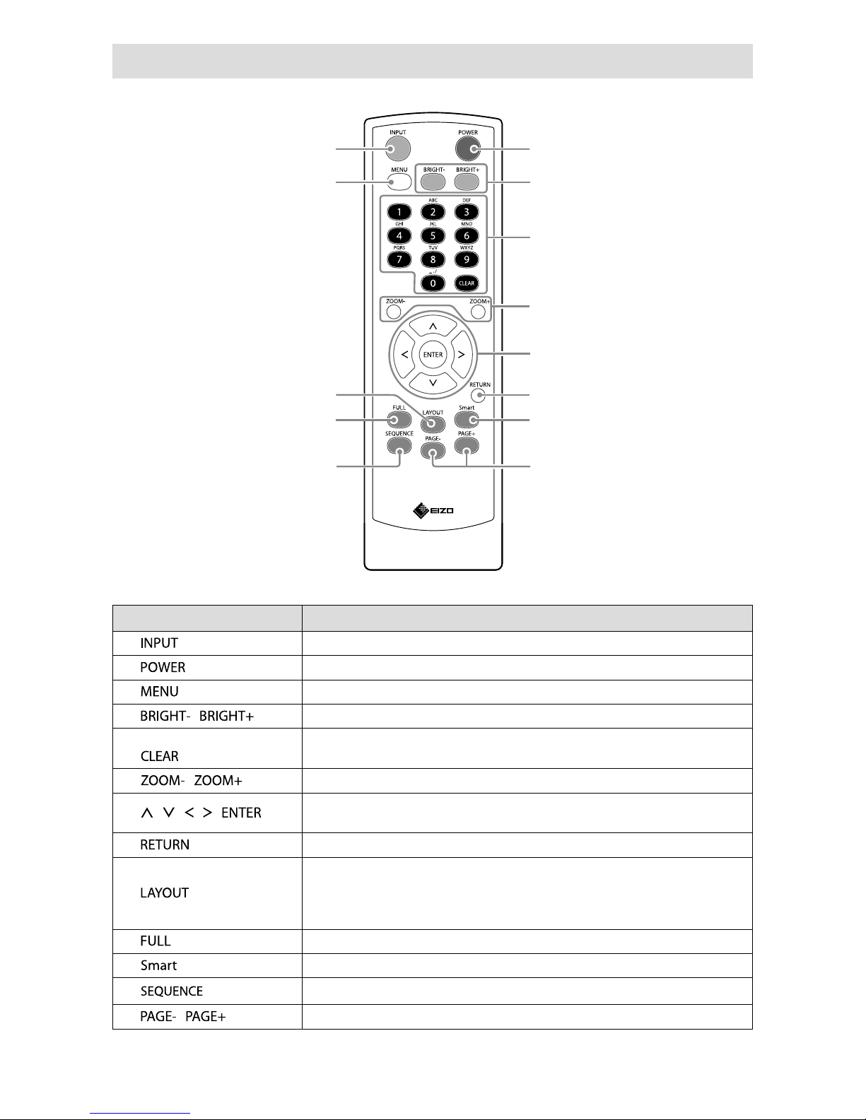
Remote Control
2
3
9
1
4
5
6
8
7
13
11
12
10
Name Description
1.
Switches input signals for display.
2.
Turns the power on or off.
3.
Used to display/exit the monitor’s Adjustment menu.
4.
/
Adjusts the brightness of the monitor screen.
5. Number Buttons ( 0 to 9 ) /
Used to enter numbers and letters.
6.
/
Adjusts the network camera display magnication.
7.
/ / / ,
Used to set and control (pan / tilt) network cameras, and congure system
settings of the monitor.
8.
Returns to the previous menu status in menu operation.
9.
Changes the live image screen layout.
Each time the button is pressed, the layout changes in the following order:
1 Screen → 3 Screens → 4 Screens → 9 Screens → 16 Screens → 8 Screens →
1 Screen.
10.
Displays / hides the menu of the live image screen.
11.
Turns the Smart function on or off.
12.
Turns the sequential display of camera images on or off.
13.
/
Changes the camera image page to display on the live image screen.
Page 11

9
English
Setup
Sets up to displaying network camera images on the monitor.
You can operate and set the monitor by using either the remote control or a USB mouse.
For details, refer to the corresponding pages.
Setup Flow
Install (page 10)
Connect (page 11)
Prepare the remote control (page 12)
Turning On the Power (page 13)
Conguring the Language (page 17)
Perform Easy Setup (page 18)
Set the following items using the setup wizard.
• Date and time on the monitor
• Monitor network information
• Automatic discovery of network cameras
• Display positions of camera images
Setup completed.
Images from the network camera(s) are displayed on the monitor.
Attention
• The language used in menus and messages displayed when the monitor is started differs according to the
sales region.
• When using the Easy Setup function, only the network cameras installed in the same subnet as the monitor
are detected. If a network camera is installed in a different subnet, the camera must be registered manually
(For more information, refer to the Installation Manual (“Chapter2 Conguring from the Monitor Screen”)).
Page 12

10
Install
●
Procedure
Attention
• When using another manufacturer’s arm, be sure to check the following points with the manufacturer and
select an arm conforming to the VESA standard.
- Screws: M8 × 1.25
- Depth of the hole: Max. 15 mm
- Clearance between the screw holes: 400 mm × 200 mm
- Thickness of plate: 2.6 mm
- Strong enough to support the total weight of the monitor and attachments such as cables.
• Use the arm within the following range (of tilt).
- Forward: 30°, Backward: 30°
• Do not turn the monitor in the vertical direction.
• Connect the cables after attaching the arm.
• As the monitor and arm are heavy, dropping or mishandling may result in injury or damage to the product.
• Periodically check the tightening of screws. If screws are loose, the monitor may detach and cause injury or
equipment damage.
1.
Lay the LCD monitor on a soft cloth spread over on a stable surface with the
panel surface facing down.
2.
Attach the monitor to the arm.
Attach the monitor using the screws specied in the User’s Manual of the arm. For details on
attachment, including the screws, refer to the User’s Manual of the arm.
Page 13

11
English
Connect
Connect the network camera and the monitor according to the following procedure.
1.
Connect the network camera to the monitor via the network hub.
1. Connect the network cable (straight cable, Cat 5e or higher) to the monitor and the LAN port of the
network hub.
Ethernet
Network hub
*1
Network cable
(To 1000Base-T port)
*1 Use a hub compatible with 1000Base-T. For some network cameras, the hub must be compatible with
the PoE function. Check the network camera’s manual for information on the appropriate hub to use.
2. Connect the network camera to the network hub.
For connecting the network camera and the network hub, refer to the network camera’s manual.
Connection examples
Network camera
Network camera
Network hub
Note
• A maximum of 16 network cameras can be connected.
Page 14

12
2.
Connect the power cord to the power connector of the monitor and plug in the
cord to the wall socket.
To power outlet
Attention
• Do not bundle cables when wiring.
• The main power switch is turned on when factory default settings are congured.
Prepare the remote control
Insert batteries into the remote control. The remote control is used for operating and conguring this
monitor.
1.
On the back of the remote control, press the knob to unlock, and remove the
cover.
2.
Input AA batteries, and slide the cover back.
Attention
• Use the remote control within the range illustrated in the diagram below.
5m
5m
20°
20°
7m
5m
30°
30°
7m
5m
• When installing multiple monitors, leave sufcient space between each monitor so that only the intended
monitor will be operated by the remote control. Otherwise, all monitors that receive the remote control signal
will operate accordingly.
Page 15

13
English
Turning On the Power
1.
Turn on the main power switch on the back of the monitor.
The main power switch is turned on when factory default settings are congured.
2.
Press on the front of the monitor or on the remote control.
The power indicator lights up blue and the live image screen is displayed. For details on the live
image screen, refer to the Instruction Manual.
Menu
Network camera image display area Message display area
Attention
• By default, it takes approximately one minute for the live image screen to be displayed after the power is
turned on (A rotating bar indicating startup is displayed). Do not turn off the monitor during startup.
• Default settings are displayed in English during conguration. For how to set the language, refer to “Conguring
the Language” (page 17).
• When the monitor is started up for the rst time, a menu for operating the monitor and network cameras is
displayed.
• When no network camera is registered, a “Not Registered” message is displayed at the network camera
image display area.
Note
• The time required to display the live image screen can be reduced (Quick Start) by changing the power-off
status. For details, refer to the Installation Manual.
• Press ‘
on the front of the monitor or on the remote control to turn off the power.
• When using a USB mouse, connect the mouse to the USB downstream port at the back of the monitor.
Page 16

14
Basic menu operations
Each menu is operated using the remote control or a USB mouse.
If the menu is not displayed, press on the remote control, or click the screen with the USB
mouse to display the menu.
When using the remote control
Item Description
To select an item Press the
/ / / buttons.
To conrm a selected item Press
.
To change a setting With setting buttons:
Press
(Excluding zoom in/out and position adjustment).
With list box:
1. Press
.
The list box is highlighted in green.
2. Select the setting with
or .
3. Press
.
To return to the previous menu level
Press .
Note
• When canceling a setting change in process, press .
To exit the setting screen
1. Select “Exit” from the list of setting items with
.
2. Press .
When using a mouse
Select and click on the item to be congured.
●
Logging In
1.
Check that (Login) is selected and press .
The login screen is displayed.
Login screen
Login
Note
• The currently selected item is lit up in green.
Page 17

15
English
2.
Enter the “Username” and the “Password”.
1. Select a text eld and press .
The text eld is highlighted in green.
2. Enter the username or password shown below and then press .
Username: “admin”
Password: “admin”
Note
• The above username and password are default settings.
Entering characters
1. Press .
The text eld is highlighted in green.
2. Press the number buttons ( 0 to 9 ).
Press a button consecutively to change over to the character next in order. For the order of character entry,
refer to the table shown below.
Button Input characters
0 0 - _ : . / (sp ace)
1 1
2 a b c A B C 2
3 d e f D E F 3
4 g h i G H I 4
5 j k l J K L 5
6 m n o M N O 6
7 p q r s P Q R S 7
8 t u v T U V 8
9 w x y z W X Y Z 9
To enter a new character, press
.
To delete a character, press
.
3. Press .
Note
• Entering network addresses
Network address text elds are separated by [.] (a period mark).
- When a three-digit number is entered, the cursor automatically moves to the next entry position.
- When entering a two-digit or one-digit number, press
to move to the next entry position.
• When using a USB mouse:
- When you enter a period “.”, the cursor moves to the next entry position.
- To enter characters, click “Keyboard” on the character entry screen. Then click the keys on the displayed
keyboard to enter characters.
Attention
• The remote control cannot be used to select the character entry screen keyboard.
Page 18

16
3.
Select “Login” and press .
The screen returns to the live image screen and (Setup) becomes available.
Setup
Page 19

17
English
Conguring the Language
Set the display language for the live screen menu and the setting screen from the setting menu.
1.
Select (Setup) and press .
The setup screen is displayed.
2.
Check that “System” is selected and press .
3.
Select “Other” and press .
Displays current settings.
1
2
4.
Select “Language” and press .
Select the list box and press . Select a language using
or
the press .
3
4
5.
Select “Apply” and press .
The setting complete screen is displayed. Select “OK” and press
6.
press .
Page 20

18
Perform Easy Setup
Necessary settings for displaying network camera images on the monitor.
1.
Start up the network camera(s).
For network camera setup, refer to the network camera’s manual.
Attention
• Connect cameras other Panasonic or AXIS network cameras using ONVIF. Check if ONVIF is enabled in the
settings of the camera.
2.
Check that “Easy Setup” is selected and press .
3.
Check that “Start” is selected and press .
The Easy Setup wizard starts and the date/time setup screen is displayed.
4.
Set the date and time on the monitor.
1
2
3
1. Select “Date/Time Display Settings” and press .
2. Set the “Date Format”, “Time Format” and “Time Zone”.
Select the list box of an item and press .
Select a setting with
or and press .
3. After completing the setting, select “Apply” and press .
The setting complete screen is displayed. Select “OK” and press
.
4. Press
.
Page 21

19
English
5. Select “Clock Setting” using
or
, then press .
5
7
6
9
6. Set the “Year”, “Month”, “Day”, “Hour”,and “Minute”.
Select the list box of an item and press .
Select a setting with
or and press .
7. After completing the setting, select “Apply” and press .
The setting complete screen is displayed. Press to select “OK”.
8. Press .
9. Select “Next” and press
.
The network settings screen is displayed.
5.
Set monitor network information.
1
2
3
4
1. Check that “IP Setting Method” is selected and press .
Select a setting with or and press .
If you selected “Manual Setting”, proceed to step 2.
If you selected “DHCP”, proceed to step 3.
2. Set the “IP Address”, “Subnet Mask” and “Gateway”.
Select the list box of an item and press .
Input the respective values. For details on the data entry method, refer to “Entering characters” (page 15).
Attention
• If your network environment does not include a gateway, you do not need to set the “Gateway” address.
Use the default setting as is, or set as “0.0.0.0”.
Page 22

20
3. After completing the setting, select “Apply” and press .
The setting complete screen is displayed. Press to select “OK”.
4. Select “Next” and press .
The network camera automatic discovery screen is displayed.
6.
Automatically discover network cameras.
1. Select “Camera Discovery”, then press .
2. Select the camera type using
or
, then press .
2
3. Check that “Start” is selected and press .
The user authentication screen is displayed.
4
5
4. Enter the “Username” and “Password” specied in the network camera.
The following values are entered as the default settings. Change the settings if necessary.
Please contact your administrator for the username and password.
- Username: “admin”
- Password: “12345”
Page 23

21
English
5. Select “OK” and press .
Automatic discovery is started and a “Searching” message is displayed.
Information on detected network cameras is displayed.
The network camera detection results are displayed.
6
Discovery Results Description
Blank
When there is no information update for the registered network cameras, or one
is not connected
New
When there is an unregistered network camera, or information was updated for a
registered network camera
Duplicate
When there is a network camera with a duplicate IP address
6. After the search is completed, select “Next” and press .
The network camera display position settings screen is displayed.
Note
• The displayed camera name is the name set on the camera side. If cameras have identical names, they are
automatically numbered (e.g. camera_1).
• When network cameras are not automatically detected, see “Chapter 4 Troubleshooting” in the Installation
Manual.
• When using an AXIS network camera
- When executing automatic detection with an incorrect user name or password, “------” is displayed for the
model name.
- When a detected IP address is a duplicate of a registered network camera, but the username and password
are correct, ‘Model Name – MAC Address’ is displayed, and ‘------’ is displayed for the model name.
Page 24

22
7.
Set the positions for displaying the network camera images.
Indicates the display
positions on the monitor
screen.
1
4
1. Press .
The “After Change” list box is selected.
2. Set a network camera to a position for displaying images.
Select the list box of a display position you wish to set and press .
Select a network camera with
or and press .
3. After completing the setting, press .
4. Select “Next” and press
.
Attention
• All cameras discovered at step 6 must be set. A network camera can only be set for one display position.
When there are incorrect settings, “Next” cannot be selected.
8.
Finish Easy Setup.
1
1. Check that “End” is selected and press .
The setting complete screen is displayed. Press to select “OK”.
Easy Setup is completed.
Page 25

23
English
9.
Close the setup screen.
1
2
1. Select “Return” and press .
2. Select “Exit” and press
.
The screen returns to the live image screen.
Check that images from the network camera(s) are displayed on the monitor.
(Example)
Page 26

24
Reference
●
Conrming the Software Version
1. Check that “System” is selected and press .
The current software version is displayed in the system information.
1
●
Connecting HDMI Devices
Connect an HDMI device to this product to switch over the network camera display to the HDMI
device.
Connection examples
HDMI cable
HH200HS (option)
HDMI device
(Network video recorder etc.)
Page 27

25
English
Compatible Resolutions / Formats
The monitor supports the following resolutions and signal format.
PC Signal
Resolution Applicable Signals
Vertical Scan
Frequency
Dot Clock
640 × 480 VGA, CEA-861 60 Hz
148.5 MHz
(M a x.)
720 × 400 VGA TEXT 70 Hz
720 × 480 (4 : 3) CEA- 861 60 Hz
720 × 480 (16 : 9) CEA-861 60 Hz
720 × 576 (4 : 3) CEA-861 50 Hz
720 × 576 (16 : 9) CEA-861 50 Hz
800 × 600 VESA 60 Hz
1024 × 768 VESA 60 Hz
1280 × 720 CEA-861 60 Hz
1280 × 960 VESA 60 Hz
1280 × 1024 VESA 60 Hz
1680 × 1050 VESA CVT, VESA CVT RB 60 Hz
1920 × 1080
*1
CEA-861 60 Hz
*1 Recommended resolution
Video Signal
- 480p / 720p / 1080p: 60 Hz
- 576p / 720p / 1080p: 50Hz
To switch among input signals
Press on the remote control to change over the input signal.
When the signal is switched, the active input port name appears at the top right corner of the screen.
Note
• on the monitor also can change the input.
Page 28

26
Adjusting screen brightness
Adjust the brightness of the monitor screen by changing the brightness of the backlight (light source
at the back of the LCD panel).
Adjustable range
0 to 100
Procedure
1. Press
or on the remote control.
The brightness adjustment menu is displayed.
2. Set the brightness with or .
The menu disappears automatically after approximately ve seconds.
Specifying color space
The color space of the input signal can be specied. Change the settings when colors are not
displayed accurately.
Attention
• “Auto” cannot be selected during PC signal input.
Adjustable range
Auto, YUV 4:2:2, YUV 4:4:4, RGB Full Range, RGB Limited Range
Procedure
1. Press
on the remote control.
The Adjustment menu is displayed.
2. Select “Color Space” with or and press .
3. Use
or for adjustment.
4. Press .
5. Press
to exit the Adjustment menu.
Page 29

27
English
●
Specications
LCD Panel Type VA (Anti-glare)
Backlight LED
Size 116.84 cm (46.0 inch) (116.8 cm diagonal)
Native resolution 1920 dots × 1080 lines
Display size (H x V) 1018.08 mm × 572.67 mm
Pixel pitch 0.53025 mm
Display colors 8-bit colors : 16.77 million colors
Viewing angles (H / V, typical) 178˚ / 178˚
Contrast ratio (typical) 4000 : 1
Response time (typical) Approx. 16 ms (black - white - black)
Approx. 6.5 ms (gray-to-gray)
LAN Standard IEEE802.3ab (1000BASE-T), IEEE802.3u (100BASE-TX)
Communication speed 1000 Mbps, 100 Mbps
Protocols TCP/IP
IP version 4
Video signal
(net work)
Terminal RJ-45
Video compression format H.264, MJPEG
Maximum resolution H.264 : 1920 × 1080
*1
MJPEG : 640 × 480
Maximum frame rate 30 fps
Maximum bit rate 8192 kbps
Number of displayed network
cameras
Max. 16 units
Video signal
(HDMI)
Input terminals HDMI
Digital signal transmission
system
TMDS (Single Link)
Digital scanning frequency
(H / V)
31 kHz to 68 kHz / 49 Hz to 61 Hz
(VGA TEXT : 69 Hz to 71 Hz)
Applicable video signal
formats
480 p / 720 p / 1080 p : 60 Hz
576 p / 720 p / 1080 p : 50 Hz
USB Port Downstream port × 2
Standard USB Specication Revision 2.0
Communication speed 480 Mbps (high), 12 Mbps (full), 1.5 Mbps (low)
Supply current Max. 500 mA / 1 port
Power supply Input 100-120 VAC ± 10%, 50 / 60 Hz 1.3 A
200-240 VAC ± 10%, 50 / 60 Hz 0.65 A
Maximum power consumption 120 W or less
Standby mode 26 W or less (with “Quick Start” set to “On”)
6 W or less (with “Quick Start” set to “Off”)
Physical
specications
Dimensions 1067.0 mm × 622.5 mm × 80.4 mm (W × H × D)
Net weight Approx. 19.6 kg
Operating
environmental
specications
Temperature 0 °C to 40 °C (32 °F to 104 °F)
Humidity 20 % to 80 % R.H. (no condensation)
Air pressure 540 hPa to 1060 hPa
Transportation/
Storage
environmental
specications
Temperature -20 °C to 60 °C (-4 °F to 140 °F)
Humidity 10 % to 95 % R.H. (no condensation)
Air pressure 200 hPa to 1060 hPa
*1 Images are not displayed when the maximum resolution is exceeded. Reduce the resolution and
/
or the bit
rate set for the network camera.
Page 30

28
●
Display capability
The table below shows the display capability of this product
H.264 (when the “Bit rate” is set at “4096kbps”)
At 1-screen display 1920 × 1080 / 30 fps
At 3-screen display 640 × 1024 / 30 fps
At 4-screen display 1920 × 1080 / 20 fps
At 8-screen display 1280 × 720 / 20 fps
At 9-screen display 1280 × 720 / 20 fps
At 16-screen display 640 × 480 / 30 fps
MJPEG
640 x 480 / 30 fps
Attention
• The above values are provided for reference purposes. Images are not displayed properly when display
capability is exceeded because of network camera settings, network installation environment or other
reasons. When images are not displayed properly, reduce the network camera resolution and bit rate. Set
network camera settings in accordance with the camera’s manual.
●
Outline Dimensions
Unit: mm
1067.0
622.5
450.0
4-M8x1.25
400.0
200.0
42.5
80.4
166.5
354.0
SIGNAL
●
Installation angle
°
30
°
30
Back Front
Attention
• To avoid an increase of the temperature inside the monitor, ensure that the installation angle is within a ± 30˚
range.
Page 31

29
English
Appendix
FCC Declaration of Conformity
For U.S.A, Canada (rated 100-120 Vac) Only
WARNING!
This equipment has been tested and found to comply with the limits for a Class A digital device, pursuant
to Part 15 of the FCC Rules. These limits are designed to provide reasonable protection against
harmful interference when the equipment is operated in a commercial environment. This equipment
generates, uses, and can radiate radio frequency energy and if not installed and used in accordance
with the instruction manual, may cause harmful interference to radio communications. Operation of this
equipment in a residential area is likely to cause harmful interference in which case the user will required
to correct the interference at his own expense.
Changes or modi cations not expressly approved by the party responsible for compliance could void the
user’s authority to operate the equipment.
Note
Use the attached speci ed cable below or EIZO signal cable with this monitor so as to keep interference
within the limits of a Class A digital device.
-
Shielded Signal Cable (enclosed)
Canadian Notice
This Class A digital apparatus complies with Canadian ICES-003.
Cet appareil numérique de le classe A est comforme à la norme NMB-003 du Canada.
CE
For Europe, etc. (rated 200-240 Vac) Only
Warning
This is a Class A product. In a domestic environment this product may cause radio interference in which
case the user may be required to take adequate measures.
Warnung
Bey dem gerät handelt es sich um ein Klasse-A-Produkt. Bei Betrieb des Geräts in Wohnumgebungen
ist gegebenenfalls durch entsprechende Maßnahmen dafür zu sorgen, dass eine Störung des Radio-
und Fernsehempfangs vermieden wird.
Avertissement
Cet appareil est de classe A. Il est susceptible de créer des interférences radio dans un environnement
domestique, dans ce cas l’utilisateur devra prendre les mesures appropriées.
Page 32

30
Page 33

(SUM-FDF4627WIP-AL)
00N0L990A1
Printed in Germany.
1st Edition-November, 2016
Copyright © 2016 EIZO Corporation. All rights reserved.
http://www.eizo.co.jp
〒 924-8566 石川県白山市下柏野町 153 番地
153 Shimokashiwano, Hakusan, Ishikawa 924-8566 Japan
http://www.eizoglobal.com
中国苏州市苏州工业园区展业路 8 号中新科技工业坊 5B
Bürgermeister-Seidl-Str. 8, 82515 Wolfratshausen, Germany
Helmut-Grashoff-Strasse 18, 41179 Mönchengladbach, Germany
 Loading...