

Page 1
Instructions for Use
Full HD 49" LCD Monitor
Important
Please read the safety information and all information delivered
with the product carefully to familiarize yourself with safe and
effective usage.
Page 2
EIZO GmbH
Siemensallee 84
76187 Karlsruhe
Germany
1084978-001
02/2018 Technical data subject to change.
Copyright © EIZO GmbH 2018.
All rights reserved.
Legal information
Warning notice system
This manual contains notices you have to observe in order to ensure your personal safety, as well as to
prevent damage to property. The notices referring to your personal safety are highlighted in the manual
by a safety alert symbol, notices referring only to property damage have no safety alert symbol. These
notices shown below are graded according to the degree of danger.
DANGER
indicates that death or severe personal injury will result if proper precautions are not taken.
WARNING
indicates that death or severe personal injury may result if proper precautions are not taken.
CAUTION
indicates that minor personal injury can result if proper precautions are not taken.
NOTICE
indicates that material damage can result if proper precautions are not taken.
If more than one degree of danger is present, the warning notice representing the highest degree of
danger will be used. A notice warning of injury to persons with a safety alert symbol may also include a
warning relating to property damage.
Qualified personnel
The product/system described in this documentation may be operated only by personnel qualified for
the specific task in accordance with the relevant documentation, in particular its warning notices and
safety instructions. Qualified personnel are those who, based on their training and experience, are capable of identifying risks and avoiding potential hazards when working with these products/systems.
Use of EIZO products
WARNING
EIZO products may only be used for the applications described in the catalog and in the relevant technical documentation. If products and components from other manufacturers are used, these must be
recommended or approved by EIZO. Proper transport, storage, installation, assembly, commissioning,
operation and maintenance are required to ensure that the products operate safely and without any
problems. The permissible ambient conditions must be complied with. The information in the relevant
documentation must be observed.
Trademarks
All names identified by ® are registered trademarks of their respective owners. Please refer to the
trademarks listed in the appendix. The remaining trademarks in this publication may be trademarks
whose use by third parties for their own purposes could violate the rights of the owner.
Disclaimer of liability
We have reviewed the contents of this publication to ensure consistency with the hardware and software described. Since variance cannot be precluded entirely, we cannot guarantee full consistency.
However, the information in this publication is reviewed regularly and any necessary corrections are included in subsequent editions.
Page 3

Table of contents
CuratOR LX491W
Instructions for Use, 02/2018
3
Table of contents
Legal information ............................................................................................................. 2
1 Introduction....................................................................................................................... 5
1.1 Contents of this document ........................................................................................5
1.2 Intended use .............................................................................................................5
1.3 User ..........................................................................................................................5
2 Safety information ............................................................................................................ 6
2.1 General safety instructions .......................................................................................6
2.2 Product-specific safety information.........................................................................10
3 Description...................................................................................................................... 11
3.1 Scope of delivery ....................................................................................................11
3.2 Monitor performance features.................................................................................12
4 Setup and installation .................................................................................................... 14
4.1 Installation site ........................................................................................................ 14
4.2 Installing the monitor...............................................................................................16
5 Connecting...................................................................................................................... 17
5.1 Safety information for connection ...........................................................................17
5.2 Connector locations ................................................................................................ 18
5.3 Connection panel....................................................................................................19
5.4 Connecting the signal cable....................................................................................21
5.5 Connecting the power cable ...................................................................................22
6 Commissioning............................................................................................................... 23
6.1 Switching on the monitor and video source ............................................................ 23
6.2 Avoiding image sticking ..........................................................................................23
6.3 Check for pixel defects ...........................................................................................24
6.4 Setting the image geometry....................................................................................24
6.5 Adjustment of monitor and video source ................................................................24
6.6 Adapting the monitor using Force Mode.................................................................26
6.6.1 Introduction to Force Mode ....................................................................... 26
6.6.2 Basic information on timing....................................................................... 27
6.6.3 Entering timing data .................................................................................. 28
6.6.4 Determining the timing data ...................................................................... 29
7 Operation......................................................................................................................... 33
7.1 Operator controls .................................................................................................... 33
7.2 Remote control .......................................................................................................34
7.3 Lock or unlock OSD menu......................................................................................35
7.4 Picture layout (PaP, PiP, PoP) ...............................................................................35
Page 4

Table of contents
4
CuratOR LX491W
Instructions for Use, 02/2018
7.5 Overview of the OSD menu .................................................................................... 37
7.6 "Picture" menu ........................................................................................................ 37
7.7 "Image" menu .........................................................................................................39
7.8 "Signal" menu .........................................................................................................41
7.9 "LUT" menu ............................................................................................................45
7.10 "Info" menu .............................................................................................................46
7.11 "Utilities" menu........................................................................................................ 47
7.12 "Force Mode" menu ................................................................................................49
7.13 "Adjust LUT" menu .................................................................................................50
8 Cleaning and maintenance ............................................................................................ 52
8.1 Cleaning..................................................................................................................52
8.2 Maintenance ...........................................................................................................53
9 Troubleshooting ............................................................................................................. 54
9.1 Fault correction ....................................................................................................... 54
10 Technical specifications ................................................................................................ 55
10.1 Monitor characteristics............................................................................................55
10.2 Power supply ..........................................................................................................55
10.3 Electronics ..............................................................................................................56
10.4 Mechanical design ..................................................................................................56
10.5 Climatic conditions..................................................................................................57
10.6 Safety regulations ...................................................................................................57
11 Dimension drawings ...................................................................................................... 58
11.1 View from front and side .........................................................................................58
11.2 Rear view................................................................................................................58
12 Spare parts / accessories .............................................................................................. 59
12.1 Accessories ............................................................................................................59
13 Appendix ......................................................................................................................... 60
13.1 Information on electromagnetic compatibility (EMC) ..............................................60
13.2 Markings and symbols ............................................................................................63
13.3 Warranty .................................................................................................................64
13.4 Repairs ...................................................................................................................65
13.5 Environmental protection ........................................................................................65
13.6 China RoHS (Restriction of Hazardous Substances) .............................................65
13.7 Additional devices...................................................................................................66
13.8 Contact ...................................................................................................................67
13.9 Trademarks............................................................................................................. 67
Index ................................................................................................................................ 68
Page 5

Introduction
1.1 Contents of this document
CuratOR LX491W
Instructions for Use, 02/2018 5
1 Introduction
1.1 Contents of this document
This document explains the functionality and the approved use of the CuratOR LX491W. To
ensure clarity, it does not contain all detailed information on this product.
The contents of this document are neither part of a previous or existing agreement, commitment or legal relationship, nor does it modify such.
Note
This documentation is available in electronic format only. It is included on the CD-ROM
provided and can be downloaded at www.eizo-or.com, or provided by the sales partner
from whom you purchased the product.
1.2 Intended use
The EIZO CuratOR LX491W is designed specifically for viewing medical images and video
data.
The LX491W is intended for use by health care professionals to display images from a variety of medical imaging devices, in particular endoscopic and PACS systems, but not mammography, on a single video monitor.
The LX491W is intended for use in the patient vicinity within the OR and other sterile medical environments, but is not intended for direct patient contact.
The LX491W can be installed in a ceiling suspension or a wall mount, or a stand.
1.3 User
User
In the following, health personnel such as surgeons or medical technicians are referred to
as the "user".
Service / service personnel
"Service" or "Service personnel" identifies authorized personnel with knowledge of medical
imaging technology, local standards for image quality requirements, and safety of medical
products, for example a hospital technician or manufacturer of medical devices.
Cleaning staff
"Cleaning staff" refers to personnel responsible for cleaning medical devices.
Page 6
Safety information
2.1 General safety instructions
6
CuratOR LX491W
Instructions for Use, 02/2018
2 Safety information
2.1 General safety instructions
Correct and safe operation of EIZO devices assume professional transport, storage, installation, and connection, as well as careful operation and service.
The devices may only be used for applications for which they are intended.
For safety reasons, the following precautions must be observed:
DANGER
Please observe all warning information present on the device and in the instructions for use.
There is a danger to life if warnings are not obeyed. Severe personal injury or damage to property
may occur.
Observe the safety requirements of EN 60601-1 (IEC 60601-1)
To prevent injury to patients and users, connect the electrical system in accordance with the safety
requirements of EN60601‑1 (IEC60601‑1) for "Safety requirements for medical electrical systems".
Connecting the protective earth conductor
If the device is connected to line power, the device must be connected to a protective ground conductor. This is the only way to ensure that the touch leakage current in a first fault event does not exceed 500 µA.
The interruption of the device's protective conductor is considered a first fault event in accordance
with EN 60601-1.
Use the following measures to ensure that the leakage currents remain below the specified limits:
• Separators for signal input unit or signal output unit
• Use of a safety isolating transformer
• Use of the additional protective ground terminal
Mounting of the monitor: The monitor's suspension arm must have its own protective ground conductor. This protective ground conductor guarantees, together with the protective ground conductor of
the monitor, that the housing leakage current always remains less than 500µA, even in the event of
a single fault condition.
No unauthorized opening of the device / no unauthorized service or maintenance work
The device may only be opened by qualified personnel. Likewise, service or maintenance work may
only be carried out by qualified personnel. There is a risk of electric shock.
No liability is accepted for death and injury to persons or damage to property resulting from work carried out by non-qualified personnel.
Do not touch components in the device
If the device is connected to the line power, components in the device are subjected to high voltages.
Touching the components may be fatal.
No contact between device and patients
The device is not suitable for direct contact with a patient. The device and patient must never be
touched simultaneously. Otherwise there is a danger to life and limb.
Page 7
Safety information
2.1 General safety instructions
CuratOR LX491W
Instructions for Use, 02/2018 7
DANGER
Please observe all warning information present on the device and in the instructions for use.
There is a danger to life if warnings are not obeyed. Severe personal injury or damage to property
may occur.
Never use defective power cables
If a damaged or unsuitable power cable is used, it could result in a fire or electric shock. Only use
power cables with PE contacts approved by the manufacturer.
Disconnect the power cable correctly
When disconnecting the power cable, always do so by holding the plug. Ensure that your hands are
dry. There is a risk of electric shock.
Do not insert any objects into the housing
Objects inserted into the housing may result in an electric shock or damage to the device.
Do not place any objects on top of the device
If you place objects on top of the device, this can lead to overheating and fire.
Avoid penetration of liquid
Liquids seeping into the device may result in electric shock or device failure.
CAUTION
Extensive damage to property may result if the device is not connected correctly
That is why you should observe the warning information:
Connection must be carried out by specialists
Please ensure that all steps are taken to avoid injuries or incorrect diagnoses.
• Only use the video cables specified by the manufacturer for the connection.
• Only use power cables with PE contacts.
• Only use power outlets with PE contacts.
• Do not connect too many devices to a power outlet or extension cable.
• Observe the information provided by the respective manufacturer.
• If required by the application or local regulations, QA software must be used for quality control
and documentation.
Connection in the USA and Canada
Molded power supply plugs must comply with the requirements for "hospital grade attachments" CSA
Std. C22.2 No.21 and UL498.
Connection in China
Only use power cables approved for China. These power cables are identified by the labels "CCC" or
"CQC".
Observe the country-specific regulations
Observe all regulations of the country in which the device is used.
Page 8

Safety information
2.1 General safety instructions
8
CuratOR LX491W
Instructions for Use, 02/2018
NOTICE
Extensive damage to property may result if the device is not connected correctly
That is why you should observe the warning information:
• Desktop installation:
Place the device on a solid and level surface. The attached stand, as well as the installation surface, must be suitable for the weight of the device.
• For mounting on a wall or ceiling suspension:
The mount unit must be suitable for the weight of the device.
• For installation in a rack:
Observe the installation sequence, and provide ventilation for the device.
Provide adequate air circulation
When installing the device, ensure that there is adequate air circulation for operation. The permissible ambient temperature range must not be violated. Otherwise, the device could be destroyed by
overheating.
Avoid sources of heat
Do not install the device in the vicinity of sources of heat, such as radiators, heating appliances or
other devices that can generate or emit heat.
Do not subject the device to jolting or shocks
The device contains sensitive electronic components that could be damaged by jolting or shocks.
Only switch on a cold device following adaptation to room temperature
If the device is brought into a room with a higher or rising temperature, condensed water will form in
and on the device. Do not switch on the device until the condensed water has evaporated. Otherwise, the device could be damaged.
Page 9

Safety information
2.1 General safety instructions
CuratOR LX491W
Instructions for Use, 02/2018 9
NOTICE
Extensive damage to property may result if the device is not connected correctly
That is why you should observe the warning information:
Transportation only in original packaging
Use the original packaging for transportation, and transport in the correct shipping position. Be sure
in particular to protect the monitor LCD modules from shocks.
Care of device / cleaning agents
• Remove water drops immediately; extended contact with water discolors the surface.
• Only clean the surfaces using the cleaning agents referred to in the Instructions for Use.
• Monitor: The screen is extremely sensitive to mechanical damage. Absolutely avoid scratches,
shocks, etc.
What to do if the device is faulty
If the following conditions exist, the device must be disconnected from the line power supply and
checked by qualified personnel:
• Damage to the plug or power cable.
• After liquid seeps into the device.
• If the device has been exposed to moisture.
• If the device does not function or if a fault cannot be eliminated using the Instructions for Use.
• If the device has been dropped and/or the housing damaged.
• If the device smells of burning or makes peculiar noises.
Be aware of the monitors aging
Note that monitors can fail as a result of aging, and that image properties such as brightness, contrast,and color value can change.
Do not touch the monitor screen
Due to mechanical pressure or electrostatic discharges, touching the screen can result in brief disturbances to the image.
Page 10
Safety information
2.2 Product-specific safety information
10
CuratOR LX491W
Instructions for Use, 02/2018
2.2 Product-specific safety information
CAUTION
Careful installation of the stand
The tilt, position, and height of the monitor can be changed when the monitor is installed
on a stand. Note the following to prevent injuries or damage when installing or adjusting
the stand:
• Make sure that you do not pinch or injure your fingers or any other parts of the body.
• Make sure the monitor does not collide with the table or other objects, which could re-
sult in damage.
CAUTION
Ensure monitor stability
Stability must be ensured after installing the monitor on a stand. An unstable stand can
cause the monitor to tip over and cause injuries or damage. Therefore make sure the
stand is stable.
• Only use a stand that has been tested for the monitor's weight and that is approved for
tilting up to 10°.
• The screw insertion depth into the monitor must be within the acceptable range.
NOTICE
Radio interference
This is a Class B device.
The device may cause radio interference or interfere with the operation of other devices in
close proximity. In this case the user is encouraged to perform appropriate measures to
correct the interference.
NOTICE
Medical System
• Do not connect devices that are not part of the medical system.
• If a stand is subsequently attached to the monitor, the stand must meet the require-
ments of standard EN60601 so that the system, comprising the stand and monitor,
meets the requirements.
Note
No zero error rate
LCD monitors do not have a zero error rate For this reason, the image parameters can
change over time, e.g. reduced luminance or changing/fading colors.
Note
Image quality
To maintain constant image quality, EIZO recommends cleaning the monitor on a regular
basis and checking image properties in accordance with all applicable local regulations.
Page 11
Description
3.1 Scope of delivery
CuratOR LX491W
Instructions for Use, 02/2018 11
3 Description
3.1 Scope of delivery
The device and various components are included in the scope of delivery. After unpacking,
check the scope of delivery for correctness and completeness.
Note
Keep the packaging material for subsequent transport of the device.
Device
The CuratOR LX491W is a Full HD 49" LCD Monitor. The monitor can be installed in a ceiling suspension, a wall mount, or a stand.
Product Order number Description
CuratOR LX491W (white) 6GF62602LA10 Full HD 49" LCD Monitor with white
housing.
CuratOR LX491W (black) 6GF62602LA11 Full HD 49" LCD Monitor with black
housing.
Components
The following components are included in the scope of delivery:
• 1 power cable for Europe
• 1 power cable for US
• 1 power cable for China
• 1 power cable for Japan
• 1 DVI cable (3 m)
• 1 CD-ROM with the documentation
• 1 set of printed safety information
• 1 set of printed information on the battery per the German battery law BattG (in German)
• 1 remote control (AAA batteries included separately)
Page 12

Description
3.2 Monitor performance features
12
CuratOR LX491W
Instructions for Use, 02/2018
3.2 Monitor performance features
The CuratOR LX491W has the following features that permit a wide range of applications:
49" large screen diagonal
With a screen diagonal of 49" and a resolution of 1920 x 1080 pixels (2 MP), the LX491W is
suitable for simultaneous use of several video sources. The monitor is particularly suited to
the display of DICOM radiographic images, or as a secondary monitor in the surgical or endoscopy area.
LED backlight
The LX491W is equipped with an LED backlight optimized for bright environments. This enables a long service life even when operated at high luminance.
Fully Automated Stability
The LX491W has a Fully Automated Stability system that keeps luminance constant in accordance with medical standards such as DICOM or Gamma 2.2, for example. The integrated stability system ensures constant luminance using a built-in light sensor in the center
of the backlight.
Preset Look Up Tables
The LX491W is precalibrated at the factory. A total of five practice oriented Look Up Tables
(LUTs) have been preset. This calibration data makes installation and maintenance easier.
As such, the monitor can be easily adapted to the respective application and local lighting
conditions.
Adjustable LUT
The adjustable LUT functions allows manual recalculation of the lookup table. This allows
users to modify the gamma model, luminance settings, or color parameters in accordance
with local needs or preferences.
The LUT is recalculated via the OSD menu without having to access external calibration
software. The reset LUT is calculated immediately, saved in the device, and used internally.
Force Mode
Using the Force Mode function, the LX491W can be adapted to special timing settings.
Video inputs
The LX491W can be connected to the imaging system using various video inputs, such as
DVI, 3G-SDI, Composite, S-Video, and VGA. BNC connectors such as RGBS, SoG, and
YPbPr can be inserted in the VGA input using an adapter cable. As a result, the LX491W
can process digital and analog standard video signals (PAL, NTSC).
Any adjustments to the video settings that may be required can be carried out using an OSD
menu (On Screen Display).
Page 13

Description
3.2 Monitor performance features
CuratOR LX491W
Instructions for Use, 02/2018 13
Simultaneous display of different video sources
The various video sources can be connected to the video inputs simultaneously and displayed on the monitor. The various signal inputs can be displayed either as a "Picture in Picture" (PiP) representation, or next to one another as "Picture and Picture" (PaP) using the
widescreen format.
Protective screen
The LX491W has an anti-glare protective screen fitted in front of the LCD panel to protect
the surface from bumps and scratches. The monitor with protective screen is protected at
the front against moisture (IP65 degree of protection).
The space between the protective screen and the panel is sealed to prevent dust from entering, thus helping ensure the internal surfaces remain clean.
Page 14
Setup and installation
4.1 Installation site
14
CuratOR LX491W
Instructions for Use, 02/2018
4 Setup and installation
CAUTION
Changes to device
Do not make any mechanical or electric changes to the device.
EIZOGmbH is not liable for changes made to the device.
4.1 Installation site
NOTICE
The power switch and connections must be accessible at all times
When installing and connecting the monitor, ensure that the power switch and the connections are accessible at all times.
NOTICE
Condensation
If the device is brought into a warm environment from a cold one, condensation may form
in the device. This could result in a short circuit when switching on the device, damaging it.
• Wait until the condensed water has evaporated, including that inside the device, before
you switch it on. This can take several hours.
NOTICE
Overheating
Ventilation holes are located on the rear of the housing.
If the ventilation holes are covered or closed, the heat generated in the monitor will not be
dissipated sufficiently.
• Do not cover the ventilation holes.
• Do not close the ventilation holes.
• The minimum distance from the back and side of the monitor to the wall must be 10 cm,
and at least 15 cm from other devices.
• The ambient temperature must be in the acceptable range of +5 °C to +40 °C.
NOTICE
Dusty environment
The monitor is intended for use in the clean environment of medical diagnostics. In dusty
environments, ventilation holes in the back can allow dust to penetrate into the monitor.
In the worst case, deposits are possible which become evident as dark spots in a white
picture and result in deterioration of the luminance.
• Protect the monitor from dust, for example through appropriate construction measures
at the installation site.
Page 15
Setup and installation
4.1 Installation site
CuratOR LX491W
Instructions for Use, 02/2018 15
Note
Reflections on the screen
The monitor has an anti-glare surface that is only effective if the screen is clean and
grease-free.
• Comply with the specifications for cleaning.
• Position the monitor to avoid reflections on the display area.
Reflections can be caused by lights, windows, furniture with shiny surfaces, or light-colored walls.
• In order to reduce reflections on the monitor, only use non-dazzling reflector bulbs for
the ceiling lighting.
Note
Shocks and impacts
The monitor is sensitive to mechanical influences. Shocks and impacts on the panel surface can lead to total failure.
• Ensure that such mechanical influences at the installation site are avoided.
Note
Movable installation
If the monitor is installed such that it can move, make sure that persons or objects in the
facility are not endangered by the monitor's range of movement.
Note
During transport, use the original packaging or service packaging.
Page 16
Setup and installation
4.2 Installing the monitor
16
CuratOR LX491W
Instructions for Use, 02/2018
4.2 Installing the monitor
NOTICE
Holders
• Mounts must be tested and approved by the manufacturer for the weight to be sup-
ported.
• An installed stand must be sufficiently stable to withstand tilting of up to 10° without top-
pling the monitor.
Note
Inaccessible cover
Before installing the monitor in the selected holder, check whether the screws for removing
the cover of the connection panel are accessible. If not, remove the connection panel
cover prior to installation.
The monitor has a VESA 400x200 mounting interface and can be installed in a suitable ceiling suspension or wall mount.
Note the following during installation:
• The maximum torque for attaching to the holder is 10 Nm.
• The screws used for attaching to the holder must meet the following requirements:
No. 4
Thread M8
Strength 8.8 in accordance with ISO 898-1
Insertion depth 10 mm to 30 mm
Page 17
Connecting
5.1 Safety information for connection
CuratOR LX491W
Instructions for Use, 02/2018 17
5 Connecting
5.1 Safety information for connection
All safety information and warnings for the device must be observed to ensure danger-free
operation.
CAUTION
Changes to device
Do not make any mechanical or electric changes to the device.
EIZOGmbH is not liable for changes made to the device.
CAUTION
Shielding measures
Follow all shielding measures in accordance with local EMC directives. If these guidelines
are not observed, device malfunction may result.
CAUTION
Grounding
The permissible leakage current is not exceeded during the first fault event in accordance
with EN60601-1. The device is grounded with an additional protective conductor to ensure
the greatest possible electric safety.
CAUTION
Excessive currents, short circuits, and ground faults
In accordance with national standards and regulations, protection against excessive currents, short circuits, and ground faults must be incorporated into the building installation.
NOTICE
Changes to device settings
Device settings may only be adjusted by service personnel.
NOTICE
Disconnecting from line power
Always set the power switch to "Off" before disconnecting the device from power. Otherwise the device could be destroyed.
Page 18
Connecting
5.2 Connector locations
18
CuratOR LX491W
Instructions for Use, 02/2018
NOTICE
Cable installation
Observe the following instructions:
• Only shielded cables are to be used for all signal connections.
• If the relevant facility is available on the connector, all plug connections must be
screwed tight or locked.
• The connecting cables must not be kinked.
• The minimum bending radius of a connecting cable generally equals five times the ca-
ble diameter.
• Do not route signal cables and power cables next to one another. Otherwise, line power
subject to heavy interference could result in reversible pixel errors.
• The device must not share a line power supply with motors or valves (interference!).
• Externally connected cables can represent a trip hazard. Make sure that all incoming
cables are safely routed.
• If the device offers strain relief mechanisms for the cables, use them to prevent unin-
tended loosening of connected cables.
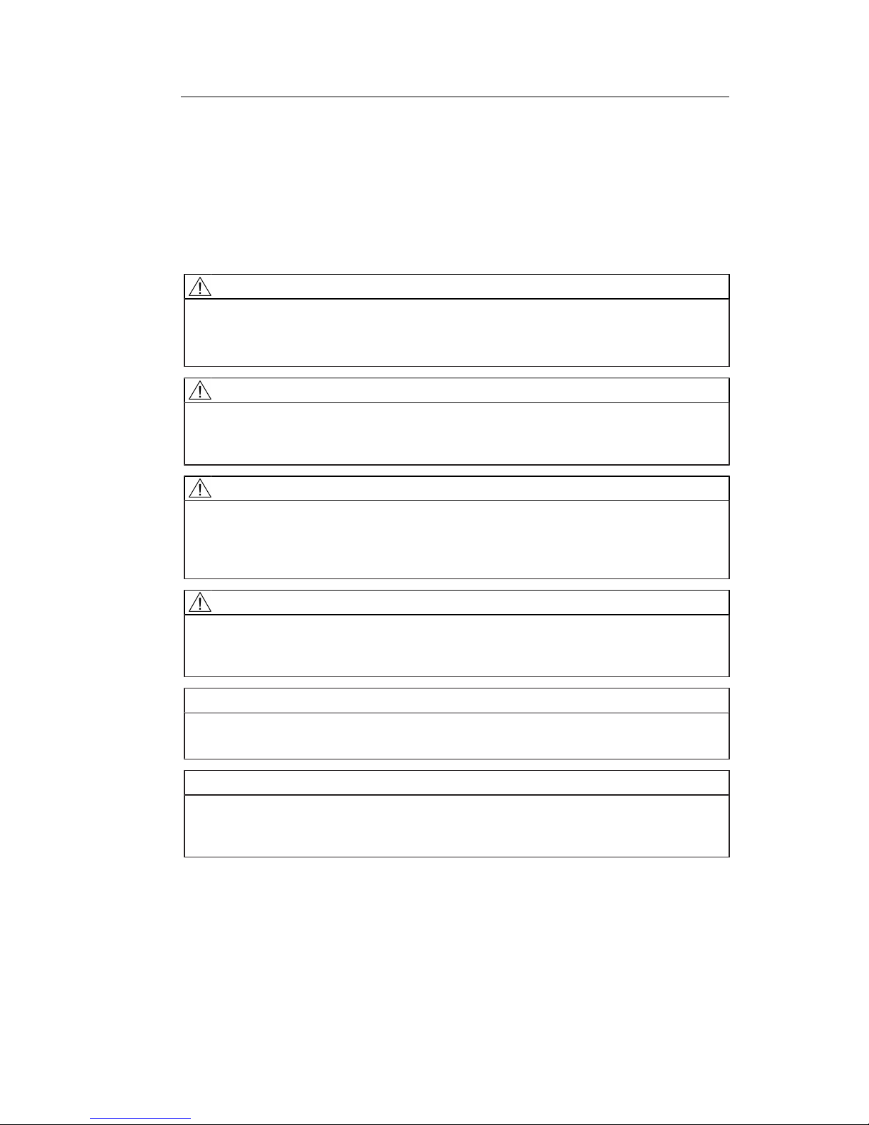
5.2 Connector locations
The connectors are located in the connection panel behind a cover on the back of the monitor. The power switch is not covered and is freely accessible.
&RYHU
6FUHZFRYHU
6FUHZFRYHU
Fig.: Rear view with cover
Page 19
Connecting
5.3 Connection panel
CuratOR LX491W
Instructions for Use, 02/2018 19
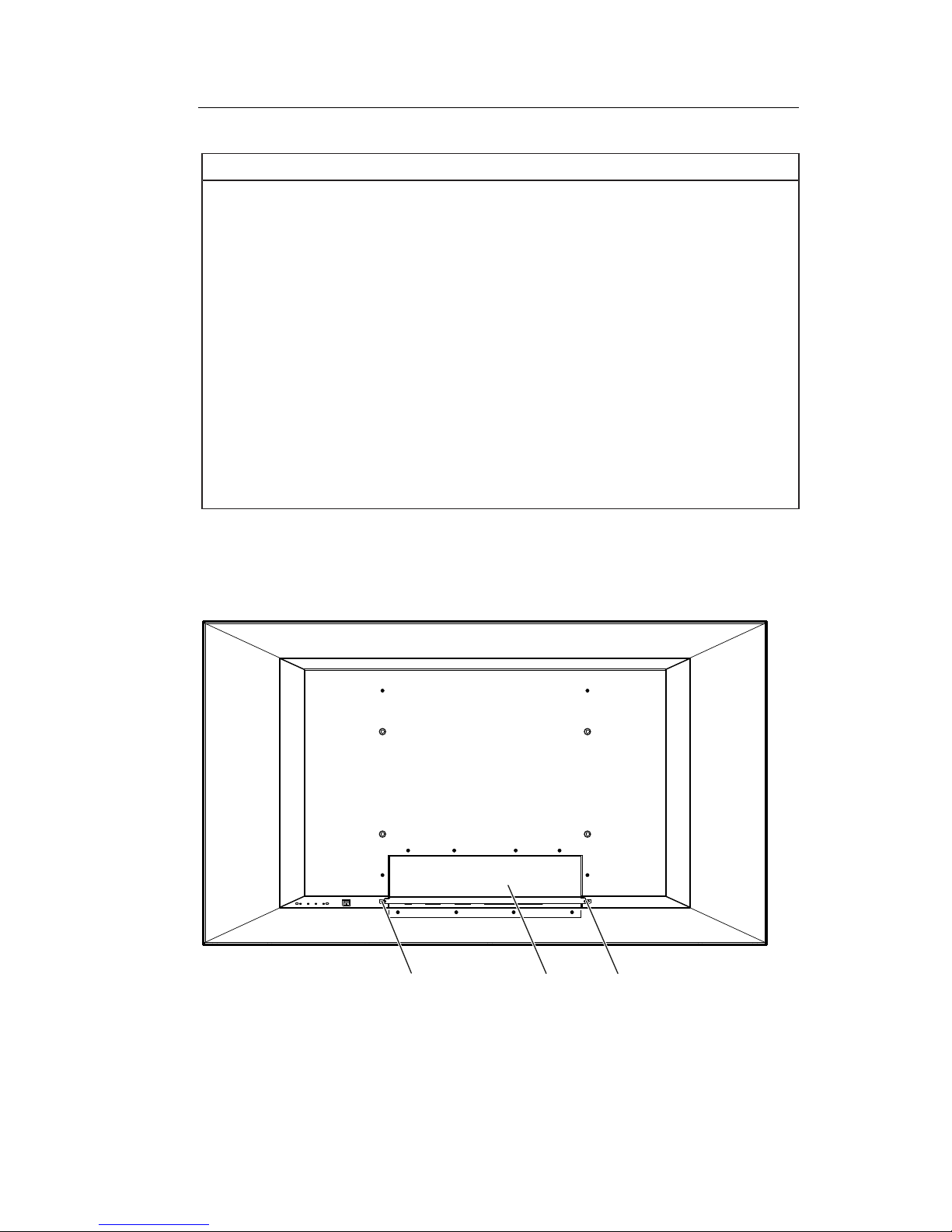
Operating
Grounding screwPower switch Connection panel
Fig.: Rear view without cover
Note
An additional protective conductor may be connected to the grounding screw.
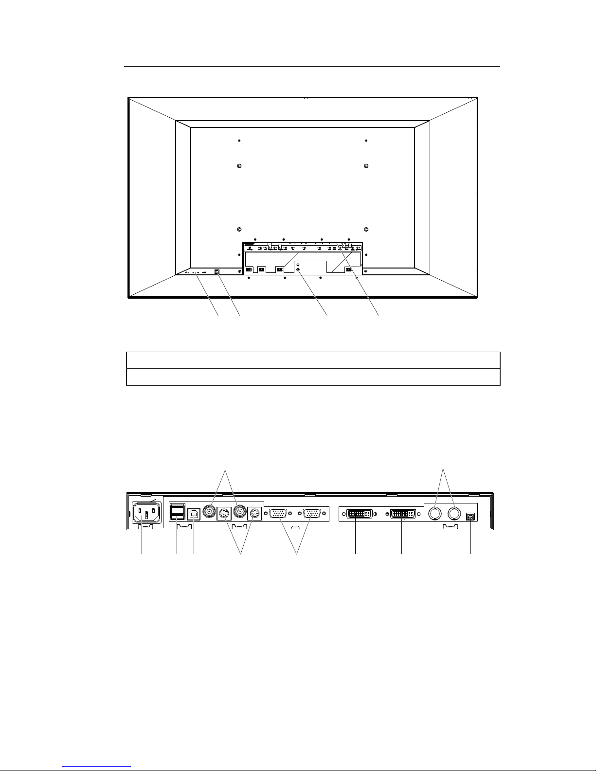
5.3 Connection panel
The connection panel is visible after removing the cover. The LX491W has connectors for
power, communication, and video input and output signals.
Power
connector
3G-SDIComposite
VGAUSB A USB B 5V/1ADVI-DDVI-I
Out In
S-Video
Out In Out In
OutIn
Fig.: LX491W connection panel
Page 20
Connecting
5.3 Connection panel
20
CuratOR LX491W
Instructions for Use, 02/2018
Signal inputs
The following signal inputs are available on the connection panel.
• VGA input (15-pin D-sub socket): In addition to a standard VGA signal, other analog signals can be connected with a suitable adapter. Examples include component, composite,
and RGB video using a multi-BNC to VGA adapter.
• DVI-I and DVI-D input
• 3G-SDI (BNC)
• S video with Y/C signal (4-pin mini-DIN socket)
• Composite (BNC)
Note
Interlaced signals
If an interlaced signal is applied to a signal input (except for the 3G-SDI input) and the
"Deinterlacing" function in the "Signal" OSD menu is set to "Normal", brightness is reduced
by approx. 15%.
The "Field to frame" and "Static mesh" deinterlacing settings cause a slight reduction in
brightness only, but can lead to comb effects.
Also refer to the "Deinterlacing" function in the "Signal" menu [}41].
Signal outputs
The following signal outputs are available on the connection panel.
• VGA output (15-pin D-sub socket):
• 3G-SDI (BNC)
• S video with Y/C signal (4-pin mini-DIN socket)
• Composite (BNC)
Additional connectors
• Power connector (appliance plug)
• USB: 2 downstream (type A) and 1 upstream (type B) connector.
• Voltage supply: 5V/1A connector to supply external devices.
Page 21
Connecting
5.4 Connecting the signal cable
CuratOR LX491W
Instructions for Use, 02/2018 21
5.4 Connecting the signal cable
CAUTION
Opening the connector panel cover
Only service may open the connector panel cover. Patients must not be present when the
cover is open.
CAUTION
Connector
Connectors may only be plugged in or removed by Service when the device is switched
off.
NOTICE
Cable
• The picture quality, interference immunity, and emitted interference of the entire system
depend on the cable quality and length.
• When using a BNC to VGA adapter cable, the signal cables, for example, red, green,
and blue, must be of the same length to prevent a loss in image quality.
• Use only the cables specified by EIZO or the transmission links available from EIZO.
Note
Video source settings
• The video source is set on the monitor using the EDID data transmitted via the DDC interface. If the video source cannot interpret the EDID data, the monitor automatically attempts to adjust to the signal clocking of the video source.
• Do not change these settings. Otherwise, the images will not be displayed correctly.
The connection panel for the signal cables and power supply is located on the back of the
monitor. All signal inputs can be connected simultaneously.
Prerequisite
• The monitor is installed in the ceiling suspension or wall mount unit, or on a stand.
• The screws for attaching the cover to the connection panel are accessible.
See also Connector locations [}18] and Installing the monitor [}16].
Procedure
1. Using a suitable tool, remove the connection panel cover.
2. Connect the signal cables to the monitor.
Note: All signal inputs can be connected simultaneously.
3. Tighten the screws to secure the signal cables.
4. Place the cover back on the connection panel.
Page 22

Connecting
5.5 Connecting the power cable
22
CuratOR LX491W
Instructions for Use, 02/2018
5.5 Connecting the power cable
DANGER
Connecting to line power
• The device is designed for line power with a grounded neutral conductor.
• To avoid risk of electric shock, this device must only be connected to line power with a
protective conductor.
• Contact the responsible building technician or a qualified electrician if you are uncertain
whether the line power is equipped with a protective conductor.
CAUTION
• Only use power cables or device connection cables with protective conductors and appliance plugs according to DIN49547, IEC60320 (max. length 3m). Furthermore, the
cable must adhere to all local safety regulations applicable to the specific country in
which the monitor is used.
• Device fuses should only be replaced in repair centers or by service personnel.
• Note for North America: Molded power plugs must comply with the requirements for
hospitals with respect to CSA Std. C22.2 No. 21 and UL498.
CAUTION
Opening the connector panel cover
Only service may open the connector panel cover. Patients must not be present when the
cover is open.
CAUTION
Connector
Connectors may only be plugged in or removed by Service when the device is switched
off.
The monitor is supplied power via an appliance plug in the connection panel on the back of
the monitor.
Prerequisite
• The monitor is installed in the ceiling suspension or wall mount unit, or on a stand.
• The screws for attaching the cover to the connection panel are accessible.
See also Connector locations [}18] and Installing the monitor [}16].
Procedure
1. Using a suitable tool, remove the connection panel cover.
2. Connect the appliance plug to the monitor power socket.
3. The power cable can be secured using a cable grip.
4. Place the cover back on the connection panel.
Page 23

Commissioning
6.1 Switching on the monitor and video source
CuratOR LX491W
Instructions for Use, 02/2018 23
6 Commissioning
Note
Factory settings
All monitors are optimally preset in the factory, such that changes are not usually required.
6.1 Switching on the monitor and video source
Note
To obtain the best possible results, the video source should support communication via the
Display Data Channel (DDC).
The monitor and video source can be switched on in any order.
Switch on
• Switch on the monitor.
– The EIZO logo appears briefly.
• Switch on the video source.
– If there is no signal the monitor displays a black screen.
– If there is a signal, the image is displayed accordingly.
Note
Image not displayed?
If an image is not displayed after the monitor is switched on and a video signal is present:
• check the system for basic connection and operating errors before contacting service
personnel.
6.2 Avoiding image sticking
Image sticking may occur with LCD monitors. Image sticking is an effect whereby a faint image of the previous screen contents can be seen after the display contents have changed.
The following measures can reduce or prevent image sticking:
• Use a screen saver with regularly changing images
• Switch off the monitor when it is no longer needed.
• The monitor has an energy saving mode:
If the application in use supports the energy saving mode, activate it.
Page 24

Commissioning
6.3 Check for pixel defects
24
CuratOR LX491W
Instructions for Use, 02/2018
Note
Energy saving (Power Management)
The monitor supports various energy saving settings, called Power Management (PM).
When PM is active, the monitor backlight switches off automatically for example, if the
monitor is without a video signal for an extended period.
Also observe the operating system manufacturer's instructions regarding power management settings.
6.3 Check for pixel defects
Pixel defects (small bright or dark dots) can occur in LCD monitors. During the manufacturing process, all monitors are checked for the permitted number of defective pixels.
Defective pixels cannot be corrected.
6.4 Setting the image geometry
The monitor automatically recognizes the standard used, and has preprogrammed set-up
values for each standard. However, depending on the graphics card used, it may still be
necessary to align and size the picture for the selected standard.
6.5 Adjustment of monitor and video source
Adjustment of resolution and refresh rate
Every LCD monitor has certain limits, such as maximum resolution and refresh rate.
• Set the graphics card for operation of the monitor in such a way as to maintain the limit
values.
Fine adjustment of brightness and contrast
CAUTION
The exact brightness and contrast settings are only possible with a photometer.
CAUTION
Fine adjustment of analog inputs: Only via 15-pin D-sub and DVI-I sockets
Fine adjustment for digital input: not necessary
• Perform the fine adjustment of the monitor only via the two analog ports (15-pin D-sub
and analog signals on the DVI-I socket).
• Digital signals on the DVI-I input do not require a fine adjustment of brightness and contrast since the signal is always displayed in an optimal manner. With a fine adjustment,
it is possible that gray scales are not displayed.
Page 25

Commissioning
6.5 Adjustment of monitor and video source
CuratOR LX491W
Instructions for Use, 02/2018 25
RGB video sources (via 15-pin D-sub or DVI-I connector) supply analog signals that are basically intended for conventional CRT monitors and that are processed directly by them.
In contrast, the analog signals must be converted into digital signals for the LCD monitor by
a video digitizer. Depending on the video source, cable length, and video mode (e.g. VGA,
SVGA, XGA), this conversion may cause certain deviations that cannot be fully corrected by
the monitor automatically.
• Perform a manual fine adjustment to obtain the optimum image display with an analog
input signal (VGA/DVI-I). During the manual fine adjustment, fine tune the monitor (or
video digitizer to be more precise) to the respective video source.
Adjusting the monitor for optimum performance with a graphics card
In order to optimize the monitor settings for the installed graphics card and guarantee that
all gray scales can be distinguished, we recommend only adjusting the brightness and contrast for the analog inputs.
Please note that these settings have no impact on the calibration in the look up table: EIZO
GmbH monitors are calibrated at the factory and maintain these settings:
• To reduce the brightness using the OSD operator controls, use a picture with 0 % gray
scale (black) and a suitable measuring instrument.
Reduce the brightness until the measuring instrument displays constant values: the measured value no longer changes.
Then increase the brightness slightly until the monitor is just above the lowest black level
(one step is generally sufficient).
• To set the white value, use a test pattern with 100 % gray value (white) and a suitable
measuring instrument.
To ensure the black value remains unchanged, set the contrast only.
• Increase the contrast until the measuring instrument no longer registers an increase in
luminance.
Then adjust the contrast regulator setting 1 or 2 steps back until the measured brightness is
just under the maximum value.
• Make sure once again that the black value has not changed.
The black value can change if significant corrections were made to the contrast. In this
case, repeat the steps above.
Result
The monitor is now configured for optimum performance with the installed graphics card. If
the luminance is still not satisfactory, you can increase the black and white values further by
adjusting the backlight in the OSD menu.
CAUTION
Permanently higher setting for backlight
The permanently higher setting for backlight reduces the service life and brightness performance.
Page 26

Commissioning
6.6 Adapting the monitor using Force Mode
26
CuratOR LX491W
Instructions for Use, 02/2018
Setting without a measuring instrument
Precise adjustment is only possible with a measuring instrument.
If there is no measuring instrument available for fine adjustment, proceed as follows:
• Use the SMPTE test pattern.
• Adjust the brightness so that image sections with 5 % and 0 % gray value still visibly
contrast.
• Adjust the contrast so that image sections with 95 % and 100 % gray value still visibly
contrast. To adapt the luminosity to the ambient lighting, adjust the backlight luminance.
CAUTION: the factory-set brightness is no longer maintained.
Note
To set the image parameters you can also use the adjustable LUT functions in the "Adjust
LUT" menu [}50].
Automatically setting the video source
In order to automatically adjust the video source, it must support communication via the Display Data Channel (DDC), and the devices must be connected correctly. When switched on,
the monitor's EDID data (Extended Display Identification Data) is read out, and the video
source can detect the monitor.
CAUTION
Installation and parameterization of the video source
Please refer to the video source manufacturer’s manual for detailed information about installation and configuration of the video source.
6.6 Adapting the monitor using Force Mode
NOTICE
Force Mode is a service tool
Force Mode should only be used by service personnel to determine an unknown timing
and implement it in the monitor.
6.6.1 Introduction to Force Mode
Various factory-set timings are saved in the monitor. As soon as a video signal is connected, an appropriate timing is sought. "Auto In Process" is displayed during this phase.
These timings are compatible with the standard video signals provided by current graphics
cards.
If no image or only an unclear image is displayed on the monitor, the signal is outside the
standard supported range. Such signals are common with older medical equipment. A timing of this sort can be set using the Force Mode function.
In many cases, a signal outside the standard range is displayed correctly without having to
use Force Mode. This is possible because a large number of known timings are saved in the
monitor.
Page 27

Commissioning
6.6 Adapting the monitor using Force Mode
CuratOR LX491W
Instructions for Use, 02/2018 27
6.6.2 Basic information on timing
Scanning with interlaced and non-interlaced procedures
There are two different scanning systems. They differ in the technology used to display the
image on the screen. TV signals, and monitors which are compatible with them, generally
use the interlaced procedure; computer signals, and monitors compatible with them, generally use the non-interlaced procedure. These two formats are not compatible; one of them
must first be converted before the signals can be processed together.
In the case of interlaced scanning, each image is divided into two separate fields. An image
therefore comprises two fields. An interlaced image is output on the screen in two scans.
The horizontal lines of the first field are scanned first, and then, again starting at the top of
the image, the horizontal lines of the second field are scanned between the first set of lines.
Field 1 consists of the lines 1 to 262 1/2, and field 2 of the lines 262 1/2 to 525. Only a few
lines are displayed at the top and bottom of each field.
3LFWXUH
6FUHHQ
)LHOG
6FDQOLQH
5HWUDFH
127(([DJJHUDWHGLQWKHYHUWLFDO
GLPHQVLRQIRUFODULW\
)LHOG
Fig.: Interlaced scanning system
3LFWXUH
6FUHHQ
6FDQOLQH
5HWUDFH
127(([DJJHUDWHGLQWKHYHUWLFDO
GLPHQVLRQIRUFODULW\
Fig.: Non-interlaced scanning system
Page 28

Commissioning
6.6 Adapting the monitor using Force Mode
28
CuratOR LX491W
Instructions for Use, 02/2018
A non-interlaced image is output to the screen such that all horizontal lines are scanned
from top to bottom in a single scan.
Horizontal timing diagram (the vertical timing diagram is identical)
Fig.: Timing diagram
Force Mode menu Timing diagram
Horizontal resolution 3 - Active video (horizontal resolution)
Vertical resolution 3 - Active video (vertical resolution)
Total horizontal lines 5 – Total number of lines (horizontal)
Horizontal blank pixels 4 – Front Porch (horizontal)
Vertical blank pixels 4 – Front Porch (vertical)
6.6.3 Entering timing data
If you know or have already determined the timing data, you can enter it directly in the OSD
"Force Mode" menu.
Entering known timing data
1. Open a test pattern with a clearly defined border (e.g.SMPTE image).
2. Open the "Force Mode" menu is the OSD.
Page 29

Commissioning
6.6 Adapting the monitor using Force Mode
CuratOR LX491W
Instructions for Use, 02/2018 29
3. Use the keys to enter the timing data in the input fields.
4. Set the "Mode" to "Active".
5. Apply the entered data by selecting "Execute function..."
Note
Always save the data with "Execute function...".
The timing data are only entered into memory with the "Execute function..." command, and
the image is then displayed with the new parameters.
6.6.4 Determining the timing data
If you know none or only part of the timing data, you can determine the data incrementally in
the "Force Mode" menu.
Note
All settings must be implemented with the zoom factor "1 to 1" ("Geometry" menu).
Sequence for determining a timing
1. Determine the start values using the auto function.
2. Enter the known data.
3. Optimize the scanning frequency.
4. Optimize the geometry and resolution.
Step-by-step instructions for setting a timing can be found in the next sections.
Page 30

Commissioning
6.6 Adapting the monitor using Force Mode
30
CuratOR LX491W
Instructions for Use, 02/2018
Determine start values using auto function
The following commands can be used to trigger automatic determination of the timing data,
and provides rough approximation of the applied timing.
1. Open a test pattern with a clearly defined border (e.g.,SMPTE image).
2. Open the "Force Mode" menu in the OSD.
3. Set "Mode" to "Start".
4. The start values are determined when you select "Execute function…"
Note: The timing data are only entered into memory with the "Execute function" command, and the image is then displayed with the new parameters.
After the "Execute function…" "Mode" switches to "Active" and you can optimize the start
values.
Entering known data
If some of the timing data are known they can be entered after determining the start values
in order to simplify the subsequent steps.
If the resolution is known for example, it can be used for the approximation of "Total horizontal lines". In this case, "Total horizontal lines" has to be greater than "Horizontal Resolution".
If "Total horizontal lines" is less than "Horizontal Resolution" during setting, that latter has to
be reduced. A larger "Horizontal Resolution" can result in the image being split vertically.
Page 31

Commissioning
6.6 Adapting the monitor using Force Mode
CuratOR LX491W
Instructions for Use, 02/2018 31
Optimize scanning frequency
The correct signal frequency now has to be set with "Total horizontal lines".
1. To set "Total horizontal lines" correctly, open a test pattern with a clearly defined border
(e.g.,SMPTE image).
2. Correct the signal frequency so that no interference is present in the picture. If the dis-
tance between interferences becomes larger, and these therefore also become fewer,
you are changing the values in the correct direction.
Optimize geometry/resolution
The active resolution range is defined by the values of the "Horizontal Resolution" and "Vertical Resolution" input fields. This range is displayed in the center of the monitor in black.
The inactive resolution range is the unused range between the active resolution and the
maximum resolution of the monitor. In Force Mode, this range is displayed gray (gray scale
monitors) or blue (color monitors).
SMPTE test pattern
Inactive resolution area
Active resolution area
To adapt the active resolution range to the actual video signal resolution, perform the following steps:
1. Open a test pattern with a clearly defined border (e.g.,SMPTE image).
2. In the "Force Mode" menu, use the "Horizontal blank pixel" input field to shift the left
edge of the SMPTE image pixel-exact to the left inside edge of the gray/blue area.
3. Correct the values in the "Horizontal Resolution" input field until the right internal border
of the gray/blue area is pixel-exact at the right edge of the SMPTE image.
Page 32

Commissioning
6.6 Adapting the monitor using Force Mode
32
CuratOR LX491W
Instructions for Use, 02/2018
4. Use the "Vertical blank lines" input field to shift the top edge of the SMPTE image pixel-
exact to the top internal border of the gray/blue area.
5. Correct the values in the "Vertical Resolution" input field until the bottom internal border
of the gray/blue area is pixel-exact at the bottom edge of the SMPTE image.
6. Apply the entered data by selecting "Execute function..."
Note: Gray/blue range not visible
If no gray/blue area is visible on the left and right sides of the image, reduce the "Horizontal Resolution" until the gray/blue area becomes visible. If no gray/blue area is visible
on the top and bottom sides of the image, reduce the "Vertical Resolution" until the gray/
blue area becomes visible.
Timing successfully set
The timing was set successfully. You can now exit the OSD menu. The monitor will recognize the newly set timing and select it whenever connected.
Note
Only one timing can be saved in Force Mode itself.
Note
Once all settings in Force Mode have been performed, the zoom factor can be changed in
the "Geometry" menu.
Page 33

Operation
7.1 Operator controls
CuratOR LX491W
Instructions for Use, 02/2018 33
7 Operation
This section describes the operator controls and functions of the monitor OSD menu.
CAUTION
Settings in the OSD menu
Changes to the OSD menu settings can impact the image properties. For this reason,
OSD menu settings should only be changed by trained personnel.
Measures in the event of a failure
Note
Device malfunction in operation
If the device is not working properly, check the system for basic connection and operating
errors before contacting service personnel.
7.1 Operator controls
The CuratOR LX491W has four keys for OSD operation located in the lower right corner.
ི
ཱི
ཱ
.H\V
3RZHUVZLWFK
Key functions
The keys have the following functions within the OSD menu:
Key Function
① • Open OSD menu
• Toggle
② • Navigate between the submenu / tabs
• Decrease/change value
③ • Navigate between the submenu / tabs
• Increase/change value
④ • Exit OSD or submenu (settings are retained)
Power switch • Switch the device on and off
Page 34

Operation
7.2 Remote control
34
CuratOR LX491W
Instructions for Use, 02/2018
7.2 Remote control
The CuratOR LX491W is delivered with a remote control.
① Standby ⑤ Down ⑨ Left
② Escape ⑥ Plus ⑩ Menu L
③ Up ⑦ Zoom ⑪ Source
④ Right ⑧ Minus ⑫ Menu R
Key Action
Menu L • Open the OSD menu
• Navigate tab to the left
Menu R • Open the OSD menu
• Navigate tab to the right
Escape Exit OSD
Up Navigate upwards in menu
Left Close submenu
Right Open submenu
Down Navigate downwards in menu
Minus Decrease value
Plus Increase value
Standby Switch the device to standby mode (this key must be held down for an
extended period to avoid inadvertently turning off the monitor when accidentally pressing the standby button)
Source Switch between connected signal sources
Zoom Change the zoom ("One to One", "Fill all", "Fill to aspect ratio")
Page 35

Operation
7.3 Lock or unlock OSD menu
CuratOR LX491W
Instructions for Use, 02/2018 35
7.3 Lock or unlock OSD menu
CAUTION
Locking and unlocking the OSD menu
• Only authorized service personnel may lock or unlock the OSD menu.
• The OSD must be locked if inappropriate operation by the user can impact the intended
use of the monitor.
The OSD menu of the LX491W is unlocked when shipped from the factory.
To lock or unlock the OSD menu, proceed as follows:
ི
ཱི
ཱ
.H\V
3RZHUVZLWFK
1. Press key ④ once.
2. Then press key ② three times.
The OSD menu is now locked or unlocked, depending on its initial state.
7.4 Picture layout (PaP, PiP, PoP)
PaP: "Picture and Picture" arrangement
Two images from a primary and secondary video source are displayed next to one another.
PiP "Picture in Picture" arrangement
The image content of the secondary video source is displayed on the main image, the primary video source.
PoP "Picture over Picture" arrangement
NOTICE
PoP image arrangement not for live operation
When working with the PoP image arrangement, there is a time delay when displaying the
images (snapshots).
• Do not use the PoP image arrangement for live operation.
Up to five images of various video sources may be displayed next to one another.
• The image from the primary video source is displayed in the larger segment in the lower
section of the window.
• The other images are displayed in a smaller format in the upper section of the window.
Page 36

Operation
7.4 Picture layout (PaP, PiP, PoP)
36
CuratOR LX491W
Instructions for Use, 02/2018
The primary video source can be selected. The four additional video sources are added automatically in accordance with the following table of compatible video source combinations:
PiP / PaP
Compatible
combinations
DVI digital DVI analog VGA S-Video 3G-SDI Composite
Video (CVBS) /
SoG
DVI digital
- - - ○ ○
1
○
DVI analog
- - - ○ ○
1
○
VGA
- - - ○ ○ ○
S-Video
○ ○ ○ - - -
3G-SDI
○
1
○
1
○ - - -
Composite
Video
(CVBS) / SoG
○ ○ ○ - - -
○ Video sources can be displayed simultaneously
- Video sources cannot be displayed simultaneously
1
Note: Flickering horizontal stripes may occur when the OSD is open.
Image settings on the PiP/PaP or PoP window
The image display and quality of the various PiP / PaP / PoP windows can be set individually.
• When "Picture layout PaP; PiP; PoP" is enabled in the "Signal" menu, an "Active adjustment window" selection appears in the main OSD menus for "Picture", "Image", and
"Signal".
• The settings for the OSD window can be applied to the main or secondary window.
Note
Picture layout PaP, PiP, PoP
• In order to adjust the PiP or PaP window settings in the "Image" menu, "Active adjustment window" must be set to "PiP/PaP Window (2)".
• The number displayed on the right side of the OSD window indicates which window is
currently active for the setting ("1": main window, "2": secondary window)
Page 37

Operation
7.5 Overview of the OSD menu
CuratOR LX491W
Instructions for Use, 02/2018 37
7.5 Overview of the OSD menu
You can use the OSD menu to change monitor settings or display information about the
monitor.
If no input signal has been applied, the OSD only offers a limited set of functions.
Fig.: OSD menu layout
7.6 "Picture" menu
Function Values Description
Active adjustment
window
Main window (1)
PiP window (2)
Default: Main window (1)
Selecting the active adjustment window
Note: The function is displayed only if the "Picture
layout PaP, PiP, PoP" function is active within the
"Signal" menu.
The "Active adjustment window" establishes the window for which the settings in this menu apply.
Page 38

Operation
7.6 "Picture" menu
38
CuratOR LX491W
Instructions for Use, 02/2018
Function Values Description
Brightness
Slider control
Default: 50
Set brightness
Adapting the representation of darker picture areas.
Note: The brightness settings are already optimized
for digital DVI signals.
Do not change these values manually, as this can
negatively impact picture quality (loss of gray scales).
Contrast
Slider control
Default: 50
Set contrast
Adapting the representation of brighter picture areas.
Note: The contrast settings are already optimized for
digital DVI signals.
Do not change these values manually, as this can
negatively impact picture quality (loss of gray scales).
Backlight
Slider control
Adjust brightness of monitor backlight
Adjustment of overall brightness to ambient lighting.
Note: The backlight settings always apply for all windows.
Color temperature
Native
9300°K
7300°K
User
Default: Native
Set the desired color temperature or hue
The color temperatures can be selected from among
three fixed settings or one adjustable setting.
It is possible to define a different color temperature
for each video input.
Set user color Define variable color temperature
The color setting defined here can be set in the
"Color temperature" menu item using the "User" setting.
Note: If the color coordinate is adjusted with this
function, some color levels may be lost. To prevent a
loss in color levels, calibrate the LUT color point with
suitable QA software.
Red Slider control
Default: 50
Select red component of display.
Green Slider control
Default: 50
Select green component of display.
Blue Slider control
Default: 50
Select blue component of display.
Hue
Slider control
Default: 50
Set the color hues for RGB and video signals.
Note: "Hue" may only be set for S-Video or Composite signals.
Saturation
Slider control
Default: 50
Set the color saturation for RGB and video signals.
Note: This menu is not displayed for the monochrome CVBS signal.
Page 39

Operation
7.7 "Image" menu
CuratOR LX491W
Instructions for Use, 02/2018 39
7.7 "Image" menu
Function Values Description
Active adjustment window
Main window (1)
PiP window (2)
Default: Main window (1)
Selecting the active adjustment window
Note: The function is displayed only if the
"Picture layout PaP, PiP, PoP" function is active within the "Signal" menu.
The "Active adjustment window" establishes
the window for which the settings in this
menu apply.
Perform auto adjustment...
Execute
Perform auto adjustment
"Position", "Phase", and "Frequency" are set
automatically upon confirmation of the selected function.
Note: "Perform auto adjustment" can only be
used for analog signal inputs.
Image size / zoom
One to One
Fill to aspect ratio
Fill screen
Default setting: One to
One
Selection between different picture size
settings:
• One to One: The picture is displayed on
screen in its original resolution.
• Fill to aspect ratio: The picture is zoomed
to the maximum screen area with retention of the aspect ratio.
• Fill screen: The picture is displayed to fill
the complete screen (1920x1080 pixels).
Page 40

Operation
7.7 "Image" menu
40
CuratOR LX491W
Instructions for Use, 02/2018
Function Values Description
Sharpness filter
Slider control
Select the sharpness setting
Note: To display the "Sharpness filter" func-
tion, "Sharpness mode" must be set to "Normal".
Use the sharpness setting to reduce scaling
artifacts or make the image "softer". A lower
value creates a "soft" image impression and a
higher value a "sharp" one.
Note: The optimum sharpness setting has to
be determined visually.
Common filters are available for the RGB
sources (VGA, DVI).
The interpolation filters depend on the input
resolution. At lower resolutions, the filter calculates the value for the non-controlled pixels.
Sharpness mode
Enhanced
Normal
Default setting: Enhanced
Setting image sharpness mode
Select "Enhanced" to display the image with
the sharpest setting.
Under "Normal", image sharpness can be set
using the "Image sharpness filter" slider control.
H-position
Slider control Shift picture in horizontal direction
V-position
Slider control Shift picture in vertical direction
Phase
Slider control
Set the frequency and phase of the input
signal
Correct potential blur in the vertical lines by
adjusting the "Frequency/Phase" setting.
Note: Use a vertical line in a "Pixel On/Off"
test pattern to make the adjustment.
Frequency
Slider control
Page 41

Operation
7.8 "Signal" menu
CuratOR LX491W
Instructions for Use, 02/2018 41
7.8 "Signal" menu
Function Values Description
Active adjustment
window
Main window (1)
PiP window (2)
Default: Main window (1)
Selecting the active adjustment window
Note: The function is displayed only if the "Pic-
ture layout PaP, PiP, PoP" function is
active.
The "Active adjustment window" establishes
the window for which the settings in this menu
apply.
Source selection
VGA / DVI1Analog /
DVI1Digital / DVI2Digital / CVBS / S-Video /
SDI /
Select source for main display
Note: This function is only displayed when the
"Source scan" function is set to "Disabled".
Selection of picture source for full format image.
Source scan
Enabled / Disabled
Default: Enabled
Activate / deactivate automatic source scan
• Enabled: If the displayed source is no
longer available, the monitor searches automatically for the next available source.
• Disabled: If the displayed source is no
longer available, no image is displayed:
The monitor does not search for available
sources. The monitor screen appears
black.
An image is not displayed again unless a
signal is applied to the set source or a different signal source is selected manually.
Page 42

Operation
7.8 "Signal" menu
42
CuratOR LX491W
Instructions for Use, 02/2018
Function Values Description
Picture layout PaP,
PiP, PoP
Enabled / Disabled
Default: Disabled
Switch the preconfigured picture layout
(PaP; PiP; PoP) on or off
• When "Picture layout PaP, PiP, PoP" is enabled, an "Active adjustment window" selection appears in the main OSD menus for
"Picture", "Image", and "Signal".
• The settings for the OSD window can be
applied to the main or secondary window.
Note: The number displayed on the right side
of the OSD window indicates which window is
currently active for the setting ("1": main window, "2": secondary window)
Set picture layout
Layout format Picture in Picture (PiP)
Picture and Picture (PaP)
Picture over Picture
(PoP)
Default: Picture in Picture
(PiP)
The following picture layouts can be selected
using this function:
Picture in Picture (PiP):
The image content of the secondary video
source is displayed on the main image (primary
video source).
Picture and Picture (PaP):
Two images from a primary and a secondary
video source are displayed next to one another.
Picture over Picture (PoP):
Up to five images of various video sources may
be displayed next to one another.
• The image from the primary video source is
magnified and displayed in the lower section of the window.
• The other images are displayed in a smaller
format in the upper section of the window.
Note: For "Picture over Picture (PoP) images"
there is a time delay when displaying images.
This setting may not be used for live mode.
Main window source Select the video sources displayed in the re-
spective "Picture in Picture (PiP)", "Picture and
Picture (PaP)", and "Picture over Picture
(PoP)" windows.
See also Picture layout (PaP, PiP, PoP) [}35]
for compatible video source combinations.
2nd Window source
Synchronization window Main window (1)
PiP/PaP window (2)
Default: Main window (1)
Select whether the main or secondary window
serves as the synchronization window.
Note: The "Synchronization Window" menu is
only available when the "Picture in Picture
(PiP)" setting is active.
Page 43

Operation
7.8 "Signal" menu
CuratOR LX491W
Instructions for Use, 02/2018 43
Function Values Description
PiP adjustments
The "PiP adjustments" menu only appears when the "Picture in Picture
(PiP)" setting is active.
Note: When initially selecting sources the "PiP adjustments" function is not
always displayed. In this case, change to another OSD menu (such as
"LUT") and then back to the "Signal" menu. The "PiP adjustments" function
is now displayed.
PiP size Select the "Picture in Picture (PiP)" window
size
H-position Slider control Set the horizontal position of the "Picture in
Picture (PiP)" window
V-position Slider control Set the vertical position of the "Picture in Pic-
ture (PiP)" window
Transparency Slider control Select the "Picture in Picture (PiP)" window
background ("opaque" or "transparent")
Saturation adjustment
Enabled / Disabled
Default: Disabled
Activates the color adjustment of "Saturation"
in the main "Picture" menu.
Deinterlacing
Field to frame
Static mesh
Normal
Default: Normal
Setting the "Deinterlacing" method
Note: The "Deinterlacing" function is shown
only in conjunction with a supporting signal
source.
Note: If an interlaced signal is connected to a
signal input (except for the 3G-SDI input) and
the "Normal" setting is selected, brightness is
reduced by approx. 15% due to the color space
conversion of the deinterlacing.
The deinterlacing settings "Field to frame" and
"Static mesh" use other deinterlacing methods
and cause only a slight reduction in brightness.
The "Static mesh" setting is optimized for still
images, but could cause comb effects in moving images.
The "Field to frame" setting is optimized for
moving images, but could cause comb effects
in still images.
Color / Monochrome
Color
Monochrome
YPbPr/YCbCr
Default: Color
Switch signal between monochrome and
color
If "Color" is set, a monochrome signal is displayed green. For correct gray scale representation, select the "Monochrome" setting.
Page 44

Operation
7.8 "Signal" menu
44
CuratOR LX491W
Instructions for Use, 02/2018
Function Values Description
ADC calibration...
Execute
Automatically calibrate A/D converter for
the applied video level
Note: This function is only displayed when the
"Saturation adjustment" function is disabled.
The video level range of the system is
checked, and the monitor set accordingly. This
results in optimum adjustment of the individual
RGB A/D converters to the video source.
The calibration results in a larger and more
flexible video level range (e.g., the full brightness is also achieved at 700mV if the video
level is limited at the value of 700 mV).
Note: A suitable test pattern is required. The A/
D converters have been factory-set and need
not be readjusted.
The function is shown only in conjunction with
a supporting signal source.
Signal change delay
Slider control
Default: 1
Note:
• The "Signal change delay" menu item is not
available unless "Source scan" is set to
"Enabled".
• "Signal change delay" can only be set when
"Picture layout PaP, PiP, PoP" is set to
"Disabled".
The following four parameters are relevant for
the function:
• H frequency
• V frequency
• V total
• Interlaced/non Interlaced
If one of these parameters changes, the monitor treats it as a timing change and initiates
resynchronization via an "Auto in progress". To
prevent this from happening as a result of each
and every minor signal disturbance, the value
representing the permissible number of faulty
or changed borders must be increased in the
case of unstable signal sources.
Note: The higher the slider setting, the longer it
will take for a desired timing change to occur
(delayed by a number of milliseconds).
Page 45

Operation
7.9 "LUT" menu
CuratOR LX491W
Instructions for Use, 02/2018 45
7.9 "LUT" menu
Function Values Description
LUT backlight command
Enabled
Disabled
Default: Enabled
Control backlight using LUT
When "Enabled” is selected, the backlight setting is determined by the selected LUT.
If "Disabled" is selected, the "Backlight" setting in the "Picture" menu applies.
Note: The backlight retains this value even if
the LUT is changed.
LUT
LUT 1-5,
LUT User
Default: LUT 1
Select the Look Up Table (LUT)
The LUT determines the monitor's gamma
curve. Using different LUTs for example, allows specific grayscale levels to be highlighted.
When the "User" LUT is selected, the LUT
can be individually set through the "Adjust
LUT" OSD menu.
See also "Adjust LUT" menu [}50].
A table with information regarding the available LUTs is displayed below the LUT selection.
Note: Select a DICOM LUT to view radiographic images.
Page 46

Operation
7.10 "Info" menu
46
CuratOR LX491W
Instructions for Use, 02/2018
7.10 "Info" menu
Function Values Description
Information
For display only
Displays the current monitor and operating data in the respective picture mode
• Serial number
• Temperature [°C]
• Operation time [h:m]
• Backlight operation time [h:m]
• BL on over 350 cd/m² [h]
• Source
• Mode
• Source signal
• 2nd Source
• Mode
• 2nd Source signal
• FW type
• FW version
• OSD version
• Config version
• SDK version
Page 47

Operation
7.11 "Utilities" menu
CuratOR LX491W
Instructions for Use, 02/2018 47
7.11 "Utilities" menu
Function Values Description
OSD
Language German
English
Default: English
Set language
German or English can be selected.
Transparency Opaque
Transparent
Half transparent
Default: Opaque
OSD background selection.
OSD timeout Off / 5sec / 10sec /
30sec / 1min
Default: Disabled
Closes the OSD menu after the specified
time of inactivity.
Position Top - left / Top - center /
Top - right / Mid - left /
Centered / Mid - right /
Bottom - left / Bottom center / Bottom - right
Default: Bottom - right
Set the location of the OSD menu on the
screen area using predefined positions
Page 48

Operation
7.11 "Utilities" menu
48
CuratOR LX491W
Instructions for Use, 02/2018
Function Values Description
Power save / DPMS
DPMS Enabled / Disabled
Default: Enabled
Enabling or disabling the DPMS (Display
Power Management System)
Note: "Enabled" and "Disabled" modes of the
DPMS standard are supported for analog signals. For digital signals, DVI-DMPM is supported at the DVI connection sockets
• If "DPMS" is activated and there is no input signal, the backlight is switched off or
dimmed.
This saves power, and increases the service life of the backlight.
Backlight Dimmed
Disabled
Default: Disabled
The "Backlight" can be set to "Dimmed"
or "Off"
When the DPMS mode is active, the backlight is either dimmed or switched off. The
controller board and power supply unit remain active. For digital signals, 5 V is also
applied to the DVI socket for external modules.
Communication
Communications interface
DDC/DVI 1 digital
DDC/DVI 2 digital
USB
Default: USB
Select the interface for communication
Serial communication is always active.
Installers can also select between USB and
DDC.
Source selection sequence
The source scan is interrupted as soon as the
first source with an active video signal is
found. This signal is then displayed.
Reset operations Reset to firmware de-
faults...
All user settings are deleted and reset to the
firmware defaults.
Page 49

Operation
7.12 "Force Mode" menu
CuratOR LX491W
Instructions for Use, 02/2018 49
7.12 "Force Mode" menu
Force Mode is used to set the timing of video sources that cannot be displayed with the timings saved in the monitor.
Function Values Description
Horizontal Resolution
Set the horizontal resolution in the active resolution
range.
Vertical Resolution
Set the vertical resolution in the active resolution
range.
Total horizontal lines
If the resolution is known, this can be used as the approximation value. The following applies: "Total horizontal lines" > "Horizontal resolution".
A larger "Horizontal resolution" can result in the image being split vertically.
Horizontal blank pixel
Set the horizontal blanking interval.
Vertical blank pixel
Set the vertical blanking interval.
Mode
Active / Start /
Inactive
Default: Inactive
Set Force Mode
• When "Active" is selected, the specified timing
values are applied with "Execute function...".
• Force Mode is switched off when "Inactive" is selected.
• When "Start" is selected, the start values for the
timing are determined using "Execute function...".
See also Determining the timing data
Execute function...
When "Start" is selected in Mode, the set video resolution is executed.
Page 50

Operation
7.13 "Adjust LUT" menu
50
CuratOR LX491W
Instructions for Use, 02/2018
7.13 "Adjust LUT" menu
Note
• The "Adjust LUT" menu is displayed only if the "User" setting is selected in the "LUT"
menu
• After each parameter change, the LUT in the device is immediately recalculated. This is
indicated in the OSD menu by the message: "Gamma table being recalculated". When
the calculation is complete, the message disappears from the OSD.
CAUTION
Check the gray levels
After each LUT recalculation performed in the "Adjust LUT" menu, it is absolutely necessary to apply an appropriate test pattern and check that all gray levels are displayed correctly.
Function Values Description
Model
• Native
• CIE 1976
• CIE (DIN 6174)
• CRT
• DICOM
• Gamma 2.0, 2.2,
2.5, 2.7, 3.0, 3.3
• Log.Lum.linear
Default: DICOM
The gamma model, which serves as the basis for recalculating the LUT, can be selected here.
Note: When "Natural" is selected, only the value for
Lmax can be changed. All other functions are hidden.
Lmin
0 - 250
Default: 40 (0.8cd/m2)
Adapt the minimum black value between 0 and 5 cd/
m
2
Page 51

Operation
7.13 "Adjust LUT" menu
CuratOR LX491W
Instructions for Use, 02/2018 51
Function Values Description
Lmax
0 - 250
Default: 80 (400cd/m2)
Adapt the maximum white value between 200 and
600 cd/m
2
Lamb
0 - 250
Default: 25 (0.5cd/m2)
Takes into account the ambient light between 0 and
5cd/m2 when recalculating the LUT.
Color adjustment
• Bluish
• Intrinsic
• Typical
Default: Intrinsic
Set the color coordinates to the following predefined
values:
• Bluish: x = 0.272; y = 0.308.
• Intrinsic: Color coordinates remain unchanged
from their intrinsic values.
• Typical: x = 0.300; y = 0.315.
X
-100 - +100
Default: 0 (x=0.272)
X color coordinate correction
When using the color setting based on the existing
defaults, it is also possible to individually modify the
color coordinates. The X color coordinate can be
adapted using the "X" function.
Y
-100 - +100
Default: 0 (y=0.308)
Y color coordinate correction
When using the color setting based on the existing
defaults, it is also possible to individually modify the
color coordinates. The Y color coordinate can be
adapted using the "Y" function.
Current target value (display only)
Page 52

Cleaning and maintenance
8.1 Cleaning
52
CuratOR LX491W
Instructions for Use, 02/2018
8 Cleaning and maintenance
8.1 Cleaning
Recommended cleaning agents and disinfectants
NOTICE
Device maintenance, cleaning and disinfecting
• Make sure liquids do not seep into the device. Liquids that seep into the device may result in an electric shock or failure of the device.
• The screen is extremely sensitive to mechanical influences. Absolutely avoid scratches,
shocks, etc. for this reason.
• Clean the screen when dirty using a microfiber cloth and, if necessary, a recommended
cleaning agent. Clean the housing parts with a recommended cleaning agent.
• Use only tested disinfectants.
• If a cleaning agent is sprayed directly onto the screen surface, use a microfiber cloth to
remove drops which run down before they reach the edge of the panel.
• Remove drops of liquid from the device immediately. Contact with liquids over a longer
period can cause discoloration or allow calcium deposits to form on the surface.
Agent class Tested cleaning agents
and disinfectants:
Further examples
Aldehyde Melsitt Aldasan 2000
Kohsolin
Gigasept FF
Cidex
Alcohol Ethyl alcohol, 96% Hospiset cloth
Peroxide compounds Perform Dismozon pur
Chlorine derivatives Terralin Quartamon Med
Disinfectants Mikrozid liquid
Nocolyse
TaskiDS5001 (DiverseyleverLabs)
Morning Mist
Surfanios Fraicheur Citron (Anios Labs)
Guanidine derivatives Lysoformin
Quaternary compounds Incidur spray, undiluted
Standard household
washing-up liquid
denk mit Fairy Ultra, Pril, Palmolive
Pyridine derivatives Activ spray, undiluted
Water Tap water
Distilled water
CAUTION
• Information on cleaning or disinfection of other system components can be obtained
from the respective instructions for use.
Page 53

Cleaning and maintenance
8.2 Maintenance
CuratOR LX491W
Instructions for Use, 02/2018 53
Prohibited cleaning agents and disinfectants
The following cleaning agents and disinfectants can bleach the paint after a longer period of
application:
Agent class Tested cleaning agents and
disinfectants:
Further examples
Petroleum spirit Petroleum spirit close to boiling Petroleum ether
8.2 Maintenance
CAUTION
Maintenance
• Maintenance may only be carried out by service personnel.
• The monitor must not be serviced in the presence of patients.
Check the settings on a regular basis
The picture quality of the monitor changes due to aging of the LCD unit and the backlight.
• Check the monitor settings at regular intervals in accordance with the local guidelines.
• Correct the settings if necessary.
Performing quality tests
You can check and change the monitor settings and calibrate them if necessary using a
photometer and suitable software.
Confirming the image quality visually after calibrating the monitor
After calibration, the monitor must be visually inspected to verify successful and correct
completion of the calibration procedure. The following two test patterns, for example, are
suitable:
• SMPTE image: The gray levels must be displayed correctly and visibly at both 5% and
95%.
• VeriLum image: The visible display of small squares in all gray scale levels confirms the
correct calibration.
Page 54

Troubleshooting
9.1 Fault correction
54
CuratOR LX491W
Instructions for Use, 02/2018
9 Troubleshooting
In normal operation, an image is displayed when the sources are set correctly. In the event
of a fault, the following checks can help localize the cause, based on the screen display and
the signal information in the OSD.
1. Check the device for the possible causes listed in the following.
2. Carry out the remedial measures before contacting service personnel.
9.1 Fault correction
Fault Cause Remedy
No picture appears on
the monitor
Monitor is in standby • Check whether the monitor is in energy
saving mode; for example, has Power
Management been activated by the signal
source and monitor?
• End standby by holding down "Standby"
on the remote control.
Power cable not connected
or connected incorrectly
• Check the power cable.
• Is the power switch in the "On" position?
• Can the OSD menu be activated?
No sync signal or video signal
• Check whether source sweep has been
switched on and the source chosen under
source selection is connected.
• Check the video cable.
Sync cable connected incorrectly
Exchange the sync cable connectors.
The video source is not
sending a video signal, or is
sending an unknown timing.
• Check the video source.
• In the "Info" OSD menu, check whether the
source was detected and that the source
signal is in the displayable range.
The video source is sending
an unknown timing
Set a different timing for the video source.
Blown fuse Contact service.
Fuzzy picture, interference in vertical lines
Scanning frequency or
phase incorrectly set.
Set the frequency and phase.
Picture is without contrast and has a strong
green shading
The video source is only
transmitting a green signal
• In the OSD "Signal" menu, switch from
"Color" to "Monochrome".
• Check the selected LUT and whether the
USER settings can be changed.
• Has the device been running for at least 20
minutes without Power Management activated?
Other Loose plug Connect the loose plug and secure it.
Defective cable Replace the defective cable.
Page 55

Technical specifications
10.1 Monitor characteristics
CuratOR LX491W
Instructions for Use, 02/2018 55
10 Technical specifications
Note
Applicability of technical specifications
All technical specifications are valid after a warm-up period of 30 minutes.
10.1 Monitor characteristics
Display type Color, TFT, IPS
Active area 1073.8 mm x 604 mm
Screen diagonal 48.5" (123.2 cm)
Resolution 1920 x 1080 pixels
Refresh rate 60 Hz
Pixel arrangement RGB vertical stripes
Pixel distance 0.55926 mm x 0.55926 mm
Contrast ratio 1300:1 typical, 900:1 minimal
Horizontal viewing angle Typically 178° for contrast ratio > 10:1
Vertical viewing angle Typically 178° for contrast ratio > 10:1
Backlight type White LEDs
Screen brightness Typically 700 cd/m²
Min. 560 cd/m²
10.2 Power supply
Power connector Non-heating appliance socket
Line voltage AC 100 - 240 V AC
Miniature fuse 2 T6.3 AH: UL 248-14, 250 V (5 x 20 mm)
Maximum current consumption 1.5 - 0.7 A
Power consumption 85 W (typical), 144 W (max)
Power consumption in Standby Mode 19 W
Page 56

Technical specifications
10.3 Electronics
56
CuratOR LX491W
Instructions for Use, 02/2018
10.3 Electronics
Multi-standard technology • Video modes with resolutions less than 1920 x 1080
can be expanded to the TFT resolution, and thus utilize the full display area (like multi-sync CRTs)
• For images with a resolution other than 1920 x 1080,
select "One to one" for "Image size / zoom" in the "Image" menu. Otherwise, you will have to deal with scaling artifacts.
Caution: If the timing is frame-buffered or frame-synchronized, the picture information may be lost; the gray scales
- the color hues for color images - are also reduced and
may be invisible.
Timing recognition The monitor detects various signals at the inputs and au-
tomatically adjusts itself to timings such as the following:
• VGA: 60-85 Hz
• SVGA: 56-85 Hz
• XGA: 60-85 Hz
• SXGA: 60-85 Hz
• FHD: 60 Hz
• UXGA: 60 Hz with vertical section
• PAL: RGB, YUV
• NTSC: RGB, YUV
• SD-SDI: 487i, 576i
• HD-SDI: 720p, 1080i, 1080p30
• 3G-SDI: 720p, 1080i, 1080p30, 1080p60
Communication interface • RS-232: Via RJ 11 socket
• USB 2.0: 2 downstream (type A), 1 upstream (type B)
• DDC: Via DVI-I
10.4 Mechanical design
Housing components Metal
Housing color • White (NCS S 1000-N)
• Black (RAL 7021)
Protective glass Optically non-reflective protective glass on both sides
Ventilation openings In rear panel
Degree of protection according to
EN60529
• Front: IP65
• Back: IP20
Connection panel On rear panel, under cover
Weight in kg 31 kg +/- 10%
Dimensions (W x H x D) in mm 1103 x 634 x 80.9
Page 57

Technical specifications
10.5 Climatic conditions
CuratOR LX491W
Instructions for Use, 02/2018 57
10.5 Climatic conditions
In operation
Temperature range +5 °C - +40 °C ambient temperature
Temperature gradient Max. 5°C/h, no condensation
Air pressure 700 -1060 hPa (3000 m - -360 m)
For transport and storage (packed)
Temperature range -20°C -+60°C ambient temperature
Temperature gradient Max. 5°C/h, no condensation
Humidity 10 -90%, non condensing, at 25°C
Air pressure 200 -1060 hPa (12000 m - -360 m)
10.6 Safety regulations
This device bears a CE mark in accordance with the provisions of Council Directive 93/42/
EEC and 2011/65/EU.
Safety standards • IEC 60601-1 (Edition 3.1)
• IEC 60950-1:2005 (Second Edition) + A1:2009 +
A2:2013
• CAN/CSA - C 22.2 60601-1:08 (Third Edition)
• GB4943.1 (non-tropical, altitude < 2000 m)
Protection class Protection class I
Degree of protection according to
EN60529
Front: IP65
Back: IP20
Medical product classification Class I according to 93/42/EEC, Appendix IX
Page 58

Dimension drawings
11.1 View from front and side
58
CuratOR LX491W
Instructions for Use, 02/2018
11 Dimension drawings
All dimensions in mm
11.1 View from front and side
11.2 Rear view
'HSWKRILQVHUWLRQaPP
0D[7RUTXH1P
0
Page 59

Spare parts / accessories
12.1 Accessories
CuratOR LX491W
Instructions for Use, 02/2018 59
12 Spare parts / accessories
12.1 Accessories
Accessories Order number Description
FST4700 Black 6GF69888BA03 Stand, black
FST4700 White 6GF69888BA04 Stand, white
Page 60

Appendix
13.1 Information on electromagnetic compatibility (EMC)
60
CuratOR LX491W
Instructions for Use, 02/2018
13 Appendix
13.1 Information on electromagnetic compatibility (EMC)
EIZO monitors were designed for the display of images and normal monitor operation.
NOTICE
Special EMC provisions are required for use of the CuratOR LX491W. Installation, assembly, and use must take place in compliance with the following instructions.
• Only use the cables included in the scope of delivery or recommended by the manufacturer. The use of other cables increases the risk of electromagnetic radiation and negatively impacts on electromagnetic interference immunity.
Cable length: max. 3 m
• Do not position any portable or mobile RF communication devices in the immediate
vicinity of the monitor. Otherwise, problem-free function of the device cannot be guaranteed.
• The monitor should not be placed on other devices or positioned in their immediate
vicinity. If devices have to be operated on or in the immediate vicinity of one another,
the monitor or system must be monitored to ensure proper operation for the defined
configuration.
• Persons connecting additional devices to the signal input or output when configuring a
medical system are responsible for ensuring compliance with standard IEC/EN
60601-1-2.
Information and manufacturer’s declaration – electromagnetic radiation
The CuratOR LX491W is intended for use in the electromagnetic environments noted below.
The customer or user of the CuratOR LX491W has to ensure that the device is used in such an environment.
Radiation test Conformity Information regarding the electromagnetic environment
RF radiation
CISPR11/EN 55011
Group 1 The CuratOR LX491W uses RF radiation for internal opera-
tion only. For this reason, the RF radiation is very low and is
therefore unlikely that the monitor will cause interference in
electronic devices in the immediate vicinity.
RF radiation
CISPR11/EN 55011
GB9254
Class B The CuratOR LX491W is approved for use in a number of en-
vironments. This includes residential areas and areas connected directly to the public low-voltage grid, such as private
homes.
Harmonic currents
IEC/EN 61000-3-2
GB17625.1
Class D
Voltage fluctuations/
flicker
IEC/EN 61000-3-3
fulfilled
Page 61

Appendix
13.1 Information on electromagnetic compatibility (EMC)
CuratOR LX491W
Instructions for Use, 02/2018 61
Information and manufacturer’s declaration – electromagnetic radiation
The CuratOR LX491W is intended for use in the electromagnetic environments noted below.
The customer or user of the CuratOR LX491W has to ensure that the device is used in such an environment.
Interference immunity test
IEC 60601
Measurement level
Compliance level Information regarding the electro-
magnetic environment
Electrostatic discharge (ESD)
IEC/EN
61000-4-2
±8 kV contact
±15 kV air
±9 kV contact
±15 kV air
It is recommended to use the device
on wood, concrete, or ceramic floors.
If the floor is made of synthetic material, the relative humidity should be at
least 30%.
Fast transient
electric disturbances (burst)
IEC/EN
61000-4-4
±2 kV (5 kHz and
100 kHz burst frequency)
for power lines
±1 kV (5 kHz and
100 kHz burst frequency)
for input/output
lines
±3 kV (5 kHz and
100 kHz burst frequency)
for power lines
±2 kV (5 kHz and
100 kHz burst frequency)
for input/output lines
The power supply quality has to correspond to that of typical industrial environments or hospitals.
Surge voltage
IEC/EN
61000-4-5
±1 kV line(s)
against line(s)
±2 kV line(s)
against ground
±2 kV line(s)
against line(s)
±3 kV line(s)
against ground
The power supply quality has to correspond to that of typical industrial environments or hospitals.
Voltage dips,
brief interruptions, and voltage fluctuations
along power
supply lines
IEC/EN
61000-4-11
<5 % VT (100 % dip
in VT) for 0.5 cycles
40 % VT (60 % dip
in VT) for 10 cycles
70 % VT (30 % dip
in VT) for 25 cycles
<5% VT (100 % dip
in VT) for 250 cycles
(5 seconds)
<5 % VT (100 % dip
in VT) for 0.5 cycles
40 % VT (60 % dip
in VT) for 10 cycles
70 % VT (30 % dip
in VT) for 25 cycles
<5% VT (100 % dip
in VT) for 250 cycles
(5 seconds)
The power supply quality has to correspond to that of typical industrial environments or hospitals.
If the monitor has to continue operation even if the power supply is interrupted, it is recommended to connect
the device to an uninterruptible power
supply or battery.
Magnetic fields
with energy
technology frequencies (50/60
Hz)
IEC/EN
61000-4-8
30 A/m 30 A/m The magnetic fields with energy tech-
nology frequencies must be in an area
that is representative of a typical location in a typical industrial environment
or hospitals.
Note: VT is the alternating current voltage before application of the measurement level.
The measurement levels were established according to IEC60601-1-2 4th Edition - Professional
Healthcare.
Page 62

Appendix
13.1 Information on electromagnetic compatibility (EMC)
62
CuratOR LX491W
Instructions for Use, 02/2018
Information and manufacturer’s declaration – electromagnetic radiation
The CuratOR LX491W is intended for use in the electromagnetic environments noted below.
The customer or user of the CuratOR LX491W has to ensure that the device is used in such an environment.
Interference immunity test
IEC 60601
Measurement
level
Compliance
level
Information regarding the electromagnetic
environment
Conducted disturbances
IEC/EN
61000-4-6
3 Vrms
150 kHz to 80
MHz
6 Vrms
ISM bands
6 Vrms Portable and mobile RF communications de-
vices may only be operated in the vicinity of
the monitor when in compliance with the recommended minimum distance.
It is determined using the formula for calculating the frequency of the transmitter.
Recommended minimum distance
d = [3.5/6] √P = 0.583 √P
d = [3.5/10] √P = 0.35 √P,
80 MHz to 800 MHz
d = [7/10] √P = 0.7 √P,
800 MHz to 2.7 GHz
In this case, "P" stands for the measured maximum nominal output power in watts (W) of the
transmitter recommended by the transmitter
manufacturer, and "d" for the recommended
minimum distance in meters (m).
The field strengths of fixed transmitters according to electromagnetic location measurementa have to be less than the compliance
level in each individual frequency rangeb.
Interference can occur when used in the vicinity of devices identified with the following symbol.
High-frequency
electromagnetic
fields
IEC/EN
61000-4-3
3 V/m
80 MHz to 2.7
GHz
10 V/m
Note: The higher frequency range applies at 80 MHz and 800 MHz.
Note: This information may not be applicable in all situations. Absorption and reflection by struc-
tures, objects, and people impact the propagation of electromagnetic waves. The measurement levels were established according to IEC60601-1-2 4th Edition - Professional Healthcare.
a
The field strengths of fixed transmitters, for example the base station for cordless and mobile telephones, radio, land mobile radio, ham radio, and television cannot be determined precisely in advance. To evaluate the electromagnetic environment using fixed transmitters, an electromagnetic location measurement should be included. If the measured field strength in the environment where the
device is used exceeds the applicable RF compliance level, observe the monitor to ensure its proper
operation. If improper operation is observed, in some circumstances additional measures may be
necessary, such as reorienting or repositioning the device.
b
The field strength beyond the frequency range 150 kHz to 80 MHz should be less than 3 V/m.
Page 63

Appendix
13.2 Markings and symbols
CuratOR LX491W
Instructions for Use, 02/2018 63
Recommended minimum distance between portable and mobile RF communications devices
and the CuratOR LX491W
The CuratOR LX491W is intended for use in an electromagnetic environment in which interference
due to electromagnetic radiation is controlled.
The customer or user of the monitor can help prevent electromagnetic interference by maintaining
the recommended minimum distance between portable and mobile RF communications devices
(transmitter) and the monitor as shown below. This is based on the maximum output power of the
communication device.
Maximum nominal
output power of
the transmitter
(W)
Recommended minimum distance according to the frequency of the
transmitter (m)
150 kHz to 80 MHz
d = 0.583 √P
80 MHz to 800 MHz
d = 0.35 √P
800 MHz to 2.7 GHz
d = 0.7 √P
0.01 0.058 0.035 0.07
0.1 0.184 0.110 0.221
1 0.583 0.35 0.7
10 1.844 1.106 2.213
100 5.833 3.5 7
For transmitters whose maximum nominal output power is not shown above, the recommended minimum distance "d" in meters (m) can be determined using the formula for calculating the frequency of
the transmitter. "P" here stands for the transmitter’s maximum measured nominal output power in
watts (W), as recommended by the transmitter’s manufacturer.
Note: For 80 MHz and 800 MHz, the recommended minimum distance for the higher frequency
range applies.
Note: This information may not be applicable in all situations. Absorption and reflection by structures, objects, and people impact the propagation of electromagnetic waves.
13.2 Markings and symbols
The markings and symbols on the device indicate the following:
Marking/symbol Description
Symbol for "Caution, observe accompanying documents".
CE marking (EU conformity mark).
MET marking, in accordance with U.S. and Canadian national regulations.
CCC marking, in accordance with for Chinese national regulations (pending).
RCM marking for conformity with Australian EMC standards (pending).
Page 64

Appendix
13.3 Warranty
64
CuratOR LX491W
Instructions for Use, 02/2018
Marking/symbol Description
Symbol for date of production for medical products.
WEEE marking: Product must be disposed of separately; materials may be
recycled.
Marking according to ACPEIP (China-RoHS).
Symbol for protective ground (ground)
"On" symbol (voltage)
"Off" symbol (voltage)
Input for service calls
Symbol for USB
Symbol for input.
Symbol for output.
Symbol for direct current.
Symbol "Comply with the instructions for use".
Symbol for "Authorized service personnel only".
Symbol for "Dangerous voltage".
13.3 Warranty
Opening of the housing, or electrical or mechanical changes on or in the device, result in
cancellation of the warranty. For warranty details, please contact the sales partner from
whom you purchased the product. These warranty conditions are neither extended nor limited by the contents of this instruction manual.
Page 65

Appendix
13.4 Repairs
CuratOR LX491W
Instructions for Use, 02/2018 65
13.4 Repairs
Please contact the sales partner from whom you purchased the product.
13.5 Environmental protection
Comply with all local requirements and laws pertaining to the disposal of devices.
The device is in compliance with directive 2011/65/EU for limiting the use of specific hazardous materials in electric and electronic devices.
13.6 China RoHS (Restriction of Hazardous Substances)
液晶显示器
LCD Monitor
型号
Model: CuratOR LX491W
根据SJ/T11364-2014《电子电气产品有害物质限制使用标识要求》特提供如下有关污染控制
方面的信息。
The following product pollution control information is provided according to SJ/T11364-2014
Marking for the restriction of the use of hazardous substances in electrical and electronic
product.
电子信息产品污染控制标志说明
Explanation of Pollution Control Label
该标志表明本产品不含有超过中国标准GB/T26572-2011《电子电气产品中限用物质的
限量要求》中限量的有毒有害物质。该标志还表示本产品废弃后可以回收利用,不应随
意丢弃。
This symbol indicates the product does not contain hazardous materials in excess of
the limits established by the Chinese standard GB/T26572-2011 Requirements of concentration limits for certain restricted substances in electrical and electronic products.
The symbol also signifies that the product can be recycled after being discarded, and
should not be casually discarded.
Page 66

Appendix
13.7 Additional devices
66
CuratOR LX491W
Instructions for Use, 02/2018
有毒有害物质或元素的名称及含量
Name and Concentration of Hazardous Substances
部件名称
Component Name
有毒有害物质或元素
Hazardous substances’ name
铅
(Pb)
汞
(Hg)
镉
(Cd)
六价铬
(Cr(VI))
多溴联苯
(PBB)
多溴二苯醚
(PBDE)
液晶纯平屏幕
LCD Flat Screen
O O O O O O
控制板
Controller Board
O O O O O O
电源
Power Supply
O O O O O O
其他 电路板
Other Circuit Boards
O O O O O O
其他(电缆等)
Others (cables, etc.)
O O O O O O
机架、底盘
Housing, Chassis
O O O O O O
附件(信号电缆、输电线等)
Acessories (signal cable, power
line, etc.)
O O O O O O
本表格依据SJ/T 11364 的规定编制。
O: 表示该有害物质在该部件所有均质材料中的含量均在GB/T 26572 标准规定的限量要求以下
X: 表示该有害物质至少在该部件的某一均质材料中的含量超出GB/T 26572 标准规定的限量要求
• 此表所列数据为发布时所能获得的最佳信息.
• 由于缺少经济上或技术上合理可行的替代物质或方案,此医疗设备运用以上一些有害物质来实现设
备的预期临床功能,或给人员或环境提供更好的保护效果。
This list is based on SJ/T 11364.
O: Indicates that this toxic or hazardous substance contained in all of the homogeneous materials for
this part is below the limit requirement in GB/T 26572.
X: Indicates that this toxic or hazardous substance contained in at least one of the homogeneous
materials used for this part is above the limit requirement in GB/T 26572.
• Data listed in the table represents best information available at the time of publication.
• Applications of hazardous substances in this medical device are required to achieve its intended
clinical uses, and/or to provide better protection to human beings and/or to environment, due to
lack of reasonably (economically or technically) available substitutes.
产品中有毒有害物质或元素的名称及含量 Table of hazardous substances’ name and concentration.
13.7 Additional devices
Connected devices such as PCs must meet the relevant safety standards.
Page 67

Appendix
13.8 Contact
CuratOR LX491W
Instructions for Use, 02/2018 67
13.8 Contact
Support during installation and for technical questions
www.eizo-or.com
13.9 Trademarks
The EIZO Logo is a registered trademark of EIZOCorporation in Japan and other countries.
EIZO is a registered trademark of EIZOCorporation in Japan and other countries.
RadiForce is a registered trademark of EIZOCorporation in Japan and other countries.
CuratOR is a registered trademark of the EIZO Corporation.
RadiCS is a registered trademark of EIZOCorporation in Japan and other countries.
RadiNET is a registered trademark of EIZOCorporation in Japan and other countries.
ScreenManager is a registered trademark of EIZOCorporation in Japan and other
countries.
Windows is a registered trademark of Microsoft Corporation in the United States and other
countries.
Apple is a registered trademark of Apple Inc.
Macintosh is a registered trademark of Apple Inc.
Mac is a registered trademark of Apple Inc.
VESA is a registered trademark of the Video Electronics Standards Association in the
United States and other countries.
HDMI is a trademark or registered trademark of HDMI Licensing, LLC in the United States
and other countries.
DICOM is a registered trademark of the National Electrical Manufacturers Association for
the publication of standards in the area of digital communication of medical information.
TORX is a registered trademark of Acument Intellectual Properties, LLC.
All other company and product names are trademarks or registered trademarks of their
respective owners.
Page 68

Index
68
CuratOR LX491W
Instructions for Use, 02/2018
Index
A
Assembly 16
C
CE marking 57
Cleaning staff 5
Connecting 21
Connection panel 20
Contact 67
D
Disposal 65
E
Energy saving 23, 24
F
Fault 54
Force Mode 26, 49
G
General safety instructions 6
Grounding 17
I
Image Sticking 23
Input 20
Installation site 14
L
Line power 22
LUT 45
Adjust 50
M
Maintenance 53
Monitor information 46
O
OSD menu
Adjust LUT 50
Force Mode 49
Image quality 37
Image setting 39
Info 46
LUT 45
Overview 37
Signal 41
Tools 47
Output 20
Overheating 14
P
Pixel defects 24
Power connector 22
Protective screen 13
S
Service 5
Shielding measures 17
Signal input 20, 21
Signal output 20
T
Technical specifications 55
Timing
Basic information 27
determining 29
Troubleshooting 54
U
User 5
W
Warranty 64
Page 69

Page 70

Siemensallee 84
76187 Karlsruhe
Germany
Copyright © 2018 EIZO GmbH. All rights reserved.
Instructions for Use, 02/2018
CuratOR LX491W
1084978-001
 Loading...