

Page 1
Instructions for Use
Color LCD Monitor
English
Important
Please read this “Instructions for Use”, and “Installation Manual”
(separate volume) carefully to familiarize yourself with safe and
effective usage.
Please retain this manual for future reference.
For monitor adjustment and settings, refer to the “Installation Manual”.
Page 2
SAFETY SYMBOLS
This manual and this product use the safety symbols below. They denote critical information. Please read
them carefully.
WARNING
Failure to abide by the information in a
WARNING may result in serious injury
and can be life-threatening.
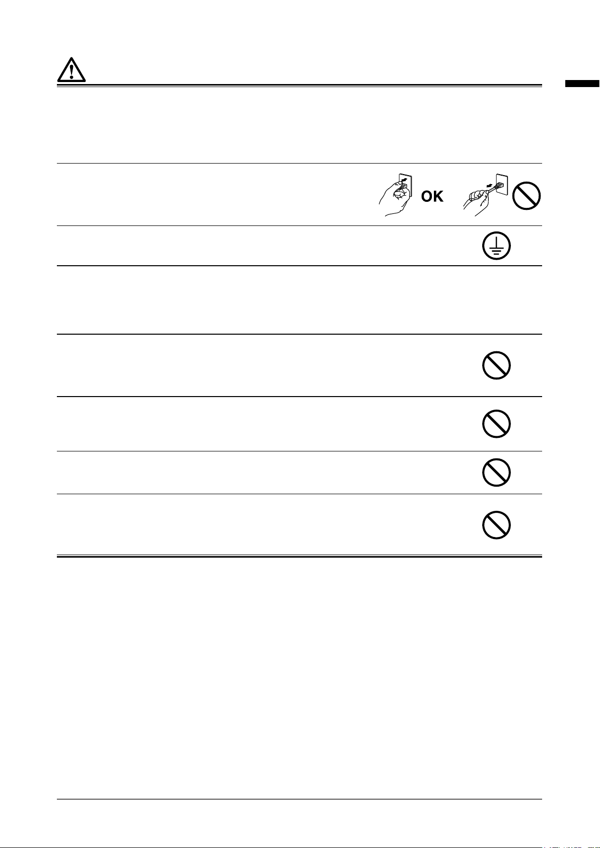
Indicates a warning or caution. For example, indicates an “electrical shock” hazard.
Indicates a prohibited action. For example, means “Do not disassemble”.
Indicates a mandatory action. For example, means “Ground the unit”.
CAUTION
Failure to abide by the information in a
CAUTION may result in moderate injury and/or
property or product damage.
This product has been adjusted specically for use in the region to which it was originally shipped. If
operated outside this region, the product may not perform as stated in the specications.
No part of this manual may be reproduced, stored in a retrieval system, or transmitted, in any form or by
any means, electronic, mechanical, or otherwise, without the prior written permission of EIZO Corporation.
EIZO Corporation is under no obligation to keep any submitted material or information condential unless
prior arrangements are made pursuant to EIZO Corporation’s receipt of said information. Although every
effort has been made to ensure that this manual provides up-to-date information, please note that EIZO
monitor specications are subject to change without notice.
2
Page 3
PRECAUTIONS
IMPORTANT
• This product has been adjusted specically for use in the region to which it was originally shipped.
If the product is used outside the region, it may not operate as specied in the specications.
• To ensure personal safety and proper maintenance, please read carefully this section and the
caution statements on the monitor.
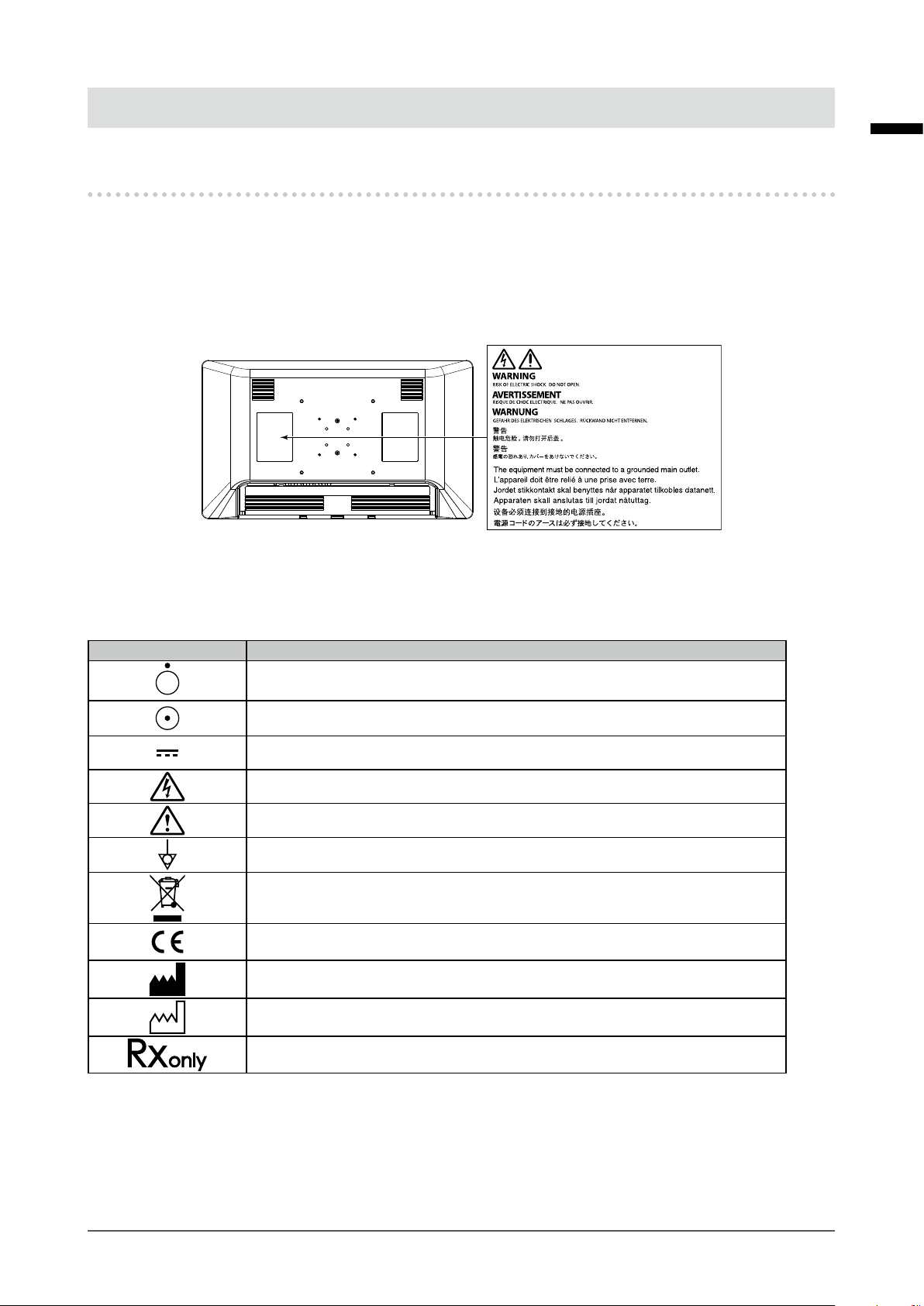
Location of the Caution Statements
English
Symbols on the unit
Symbol This symbol indicates
Power Switch: Press to turn the monitor’s power off.
Power Switch: Press to turn the monitor’s power on.
Direct current
Alerting to electrical hazard
CAUTION: Refer to “SAFETY SYMBOLS” (page 2).
Potential equalization terminal
WEEE marking:
CE marking:
Manufacturer
Date of manufacture
Caution: Federal law (USA) restricts this device to sale by or on the order of a
licensed healthcare practitioner.
Product must be disposed of separately; materials may
be recycled.
EU conformity mark in accordance with the provisions of
Council Directive 93/42/EEC and 2011/65/EU.
PRECAUTIONS
3
Page 4
WARNING
If the unit begins to emit smoke, smells like something is burning, or makes strange noises,
disconnect all power connections immediately and contact your EIZO representative for advice.
Attempting to use a malfunctioning unit may result in re, electric shock, or equipment damage.
Do not disassemble or modify the unit.
Opening the cabinet or modifying the unit may result in re, electric shock, or burns.
Use multiple units or have ready a standby unit.
Prepare an appropriate countermeasure in case the monitor fails.
Do not turn the bushing to x the AC adapter power cable.
Doing so may result in re, electric shock, or equipment damage.
Refer all servicing to qualied service personnel.
Do not attempt to service this product yourself as opening or removing covers may result in re, electric
shock, or equipment damage.
Keep small objects or liquids away from the unit.
Small objects accidentally falling through the ventilation slots into the cabinet or spillage
into the cabinet may result in re, electric shock, or equipment damage. If an object or
liquid falls/spills into the cabinet, unplug the unit immediately. Have the unit checked by
a qualied service engineer before using it again.
Install the unit correctly on a sturdy and stable location using an arm or stand.
In accordance with the User Manual of each product, install it correctly on a sufciently sturdy desk or wall.
If the unit is installed incorrectly, it may drop or fall over, resulting in personal injury or equipment damage.
If the unit falls, disconnect the power immediately and ask your local EIZO representative for advice. Do not
continue using a damaged unit. Using a damaged unit may result in re or electric shock.
Use the unit in an appropriate location.
Otherwise, re, electric shock, or equipment damage may result.
• Do not place outdoors.
• Do not place in any form of transportation (ships, aircraft, trains, automobiles, etc.).
• Do not place in dusty or humid environments.
• Do not place in locations where water may be splashed on the screen (bathrooms, kitchens,
etc.)
• Do not place in locations where smoke or steam come in direct contact with the screen.
• Do not place near heat generating devices or humidiers.
• Do not place in locations where the product is subject to direct sunlight.
• Do not place in environments with ammable gas.
• Do not place in environments with corrosive gases (such as sulfur dioxide, hydrogen sulde,
nitrogen dioxide, chlorine, ammonia, ozone, etc.)
• Do not place in environments with dust, components that accelerate corrosion in the
atmosphere (such as sodium chloride and sulfur), conductive metals, etc.
To avoid danger of suffocation, keep the plastic packing bags away from babies and children.
Use the enclosed power cord and connect to the standard power outlet in your country.
Be sure to use within the rated voltage of the power cord. Otherwise, re or electric shock may result.
Power supply: 100-240Vac 50/60Hz
PRECAUTIONS
4
Page 5
WARNING
Use the enclosed AC adapter.
The enclosed AC adapter (AHM250PS48T) is for use with this product only. Do not use the AC adapter with
other equipment. Do not use an AC adapter designed for other devices with this product.
Connecting to power sources that do not match the power ratings of the AC adapter may result in re or
electric shock.
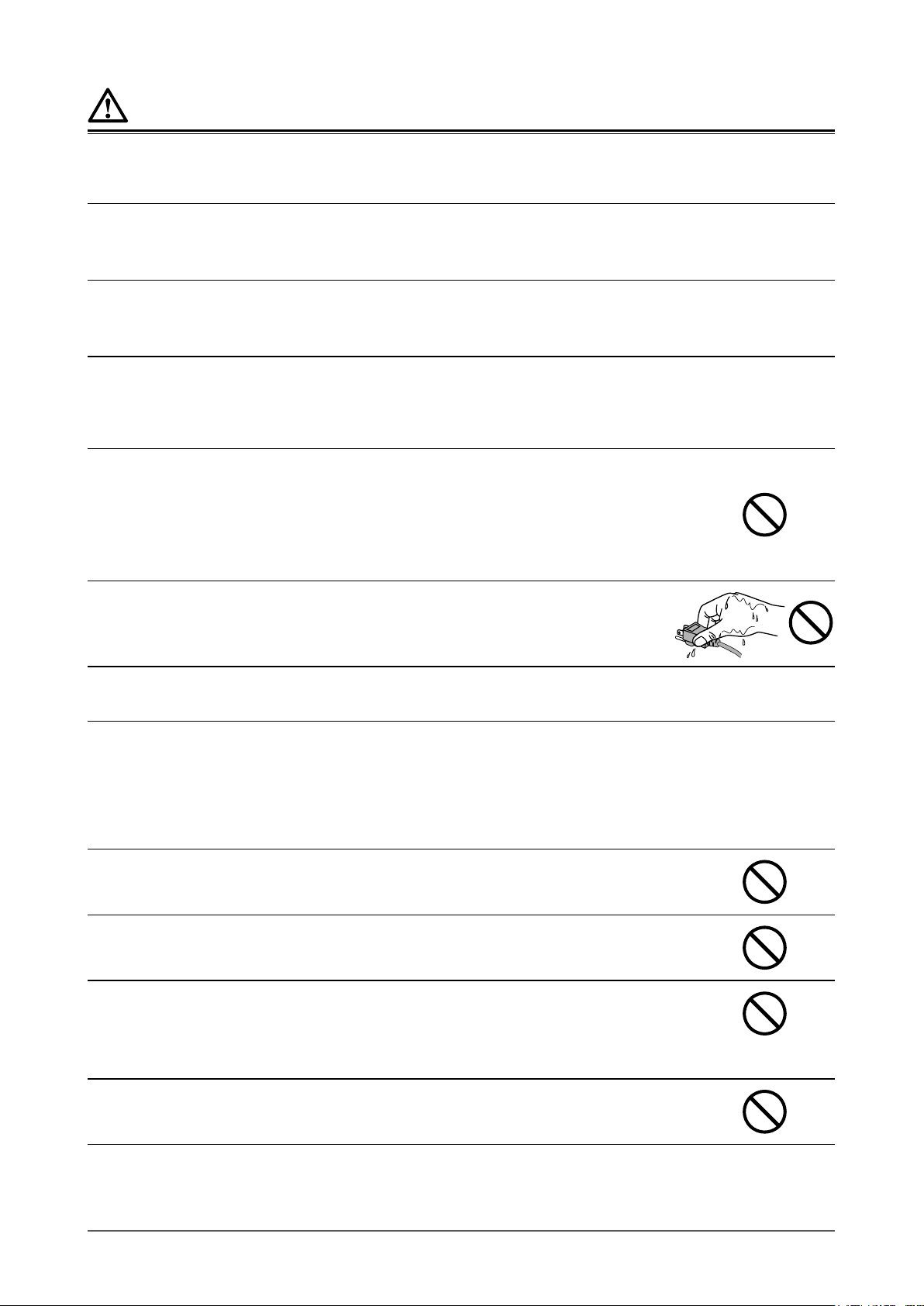
To disconnect the power cord or adapter power cable, grasp the
plug rmly and pull.
Tugging on the cord or cable may damage it and result in re or electric
shock.
The equipment must be connected to a grounded main outlet.
Failure to do so may result in re or electric shock.
Use the correct voltage.
• The unit is designed for use with a specic voltage only. Connection to another voltage than that specied in this
“Instructions for Use” may cause re, electric shock, or equipment damage.
Power supply: 100-240Vac 50/60Hz
• Do not overload your power circuit, as this may result in re or electric shock.
Handle the power cord and AC adapter with care.
Handle the power cord and AC adapter with care.
Do not place heavy objects on, pull or tie the power cord or the AC adapter. Using a
damaged cord or AC adapter may result in re or electric shock.
English
The operator should not touch the patient while touching the product.
This product has not been designed to be touched by patients.
Never touch the plug, AC adapter or power cord during a thunderstorm.
Touching them may result in electric shock.
Do not touch a damaged LCD panel directly with bare hands.
Liquid crystal is poisonous. If any part of your skin comes in direct contact with the
panel, wash thoroughly. If liquid crystal enters your eyes or mouth, immediately ush
with large amounts of water and seek medical attention.
PRECAUTIONS
5
Page 6
CAUTION
Check the operational state before use.
• Begin use after ensuring that there are no problems with the displayed image.
• When using multiple units, begin use after ensuring that the images are displayed appropriately.
Securely x cables / cords that have a xing feature.
If they are not xed securely, cables / cords may disconnect, and subsequently images may be cut off and
your operations may be disrupted.
Handle with care when carrying the unit.
Disconnect the power cord and cables when moving the unit. Moving the unit with the power cord or cables
attached is dangerous and may result in injury.
Carry or place the unit according to the correct specied methods.
• Monitors of size 30 inches and above are heavy. When unpacking and/or carrying the monitor, ensure at least two
people are involved.
Dropping the unit may result in injury or equipment damage.
Do not block the ventilation slots on the cabinet.
• Do not place any objects on the ventilation slots.
• Do not install the unit in a place with poor ventilation or inadequate space.
• Do not use the unit laid down or upside down.
Blocking the ventilation slots prevents proper airow and may result in re, electric
shock, or equipment damage.
Do not touch the plug or AC adapter with wet hands.
Doing so may result in electrical shock.
Use an easily accessible power outlet.
This is to facilitate disconnecting the power in case of a problem.
The AC adapter becomes hot during use.
• Do not cover or place anything on top of the AC adapter. Do not place the AC adapter on top of things that trap heat
such as carpets, blankets, etc. Keep the AC adapter away from direct sunlight and heat sources. Failure to do so
may result in re.
• Before moving the monitor, be sure to turn off the power switch, disconnect the power plug from the power outlet,
and wait until it has cooled completely.
Do not suspend the AC adapter in midair.
Using the adapter while it is hanging suspended may result in re or electrical shock.
Do not place the AC adapter in a vertical orientation.
Otherwise, dust or water may enter the adapter and may result in re or electrical shock.
Do not subject the unit and the AC adapter to any impact due to dropping them
or any other causes.
Using the adapter after it has been subjected to impact may result in re or electrical
shock.
Do not subject the LCD panel to strong impact.
Otherwise, glass will break and may result in injury.
PRECAUTIONS
6
Page 7
CAUTION
Periodically clean the area around the power plug and the ventilation slot of the monitor and the AC
adapter.
Dust, water, or oil on the plug may result in re.
Unplug the unit before cleaning it.
Cleaning the unit while it is plugged into a power outlet may result in electric shock.
If you plan to leave the unit unused for an extended period of time, disconnect the power plug from
the wall socket after turning off the power switch for safety and power conservation.
English
PRECAUTIONS
7
Page 8

About the monitor
Intended Use
This product is intended to be used to display medical images, such as endoscopic surgery images.
Attention
• This product is not intended for diagnostic purposes.
• This product should be set to horizontal view mode.
• This product may not be covered by warranty for uses other than those described in this manual.
• The specications stipulated in this manual are only applicable when the enclosed power cord is used.
• Only use optional products manufactured or specied by us with this product.
Precautions for Use
• Parts (such as the LCD display, fan, etc.) may deteriorate from long-term usage. Periodically check that
they are operating normally.
• When the screen image is changed after displaying the same image for extended periods of time, an
afterimage may appear. Use the screen saver or power save function to avoid displaying the same image
for extended periods of time.
• If the monitor displays continuously over a long period of time, dark smudges or burn-in may appear. To
maximize the life of the monitor, we recommend the monitor be turned off periodically.
• An afterimage may appear even after a short period has elapsed depending on the displayed image. If
this occurs, changing the image or leaving the power off for a few hours may solve the problem.
• The backlight of the LCD panel has a xed lifetime. When the screen becomes dark or begins to icker,
please contact your local EIZO representative.
• The LCD panel is manufactured using high-precision technology. Although, missing pixels or lit pixels
may appear on the LCD panel, this is not a malfunction. Percentage of effective dots: 99.99 % or higher.
• Do not press on the panel or edge of the frame strongly, as this may result in display malfunctions, such
as interference patterns, etc. If pressure is continually applied to the panel, it may deteriorate or damage
it. (If the pressure marks remain on the panel, leave the monitor with a black or white screen. The
symptom may disappear.)
• Do not scratch or press on the panel with any sharp objects, as this may result in damage to the panel.
Do not attempt to wipe with tissues as this may scratch the panel.
• Condensation may form on the surface or interior of this product when it is brought into a cold room,
when the temperature suddenly rises, or when it is moved from a cold room to a warm room. Also, if
the air conditioner is turned on after this product has been kept in a warm room or a room with high
humidity for an extended period, change the facing or placement of this product so that the air from the
air conditioner does not blow directly on this product. If the air from an air conditioner blows directly on
to the display surface, condensation may form on the inside of the protection panel. In that case, do not
turn the monitor on. Instead wait until the dew condensation disappears, otherwise it may cause some
damage to the monitor.
• It takes about 30 minutes for the performance of electrical parts to stabilize. Please wait 30 minutes or
more after the monitor power has been turned on or the monitor has recovered from the power saving
mode, and then adjust the monitor.
About the monitor
8
Page 9
Cleaning
Periodic cleaning is recommended to keep the monitor looking new and to prolong its operation lifetime.
Gently wipe off any dirt on the cabinet or panel surface with a soft cloth soaked in a small amount of
water or one of the chemicals listed below.
Chemicals that may be used for cleaning
Material name Product name
Ethanol Ethanol
Isopropyl alcohol Isopropyl alcohol
Benzalkonium chloride Welpas
Glutaral Sterihyde
Glutaral Cidex Plus28
Ammonia Ammonia water
Hydrogen peroxide Hydrogen peroxide solution
Alkyldiaminoethylglycine hydrochloride Satenidin solution
Benzalkonium chloride Zalkonin solution
Benzethonium chloride Bezeton solution
Attention
• Do not use chemicals on a frequent basis. Chemicals such as alcohol and antiseptic solution may cause gloss
variation, tarnishing, and fading of the cabinet or panel, and also quality deterioration of the image.
• Never use any thinner, benzene, wax, or abrasive cleaner, which may damage the cabinet or panel.
• Do not let chemicals come into direct contact with the monitor.
English
About the monitor
9
Page 10

CONTENTS
PRECAUTIONS ...................................................... 3
IMP ORTANT .............................................................. 3
About the monitor ................................................. 8
Intended Use ............................................................. 8
Precautions for Use ................................................. 8
Cleaning .................................................................... 9
CONTENTS ........................................................... 10
Chapter 1 Introduction ..................................... 11
1-1. Features ........................................................11
1-2. Package Contents ........................................11
1-3. Controls and Functions ..............................12
Chapter 2 Installation / Connection ................ 15
2-1. Before Installing the Product .....................15
Installation Requirements ..............................15
●
2-2. Installing the Product ..................................16
2-3. Connecting the Power Cord .......................17
2-4. Connecting the Cables ................................18
2-5. Installing the Cable Cover ...........................19
2-6. Turning On the Power ..................................19
Chapter 3 If No Image Is Displayed ................ 20
Chapter 4 Specications ................................. 21
4-1. Specications List .......................................21
4-2. Displayable Input Signals ......................... 23
4-3. Optional Accessories ................................. 23
Appendix .............................................................. 24
Medical Standard ................................................... 24
EMC Information .................................................... 25
Warning for Radio interference ............................ 29
10
CONTENTS
Page 11

Chapter 1 Introduction
1-1. Features
High-quality and high-resolution Ultra High Denition (UHD)
●
• The UHD LCD display allows for display of high-quality, high-resolution medical images.
• Equipped with front protection panel
• LED Backlight
Supports multiple I/O
●
• 3G-SDI: 4 inputs / 4 outputs (UHD compatible display can be output to four terminals via 3G-SDI.*1)
• DVI signal: 2 inputs / 1 output
• DisplayPort: 1 input (DisplayPort 1.2 SST UHD compatible.*2)
Other functions
●
• S.R.S.C. (Smart Resolution with Sparse Coding) function
Reduces blur on input images, allowing for a crisp, clear display.
• 2 screen display function
Permits parallel display of two input images.
• Gamma switch function
Gamma function is installed according to usage.
Simplied DICOM
• Color temperature switch function
Color temperature switch function is installed according to usage.
• External remote function
Allows for remote control via USB, RS-232C or GPI terminal.
• Direct input signal switching can be assigned to a function button.
• IP32 protection structure (Excluding the AC adapter)
The IPx2 protection level is effective when the monitor is installed so it cannot be put at a slant.
®
image is supported.
English
*1 Either Square Division (SQD) or Two-Sample Interleave Division (2SI).
*2 SST
Single Stream Transport
:
1-2. Package Contents
Check that all of the following items are included in the package.
Note
• It is recommended that the box and packing materials be stored so that they can be used to move or transport
this product.
• Monitor
• Power cord
• AC adapter (AHM250PS48T)
• Cable cover (with screws)
• Monitor attachment screw
- (M4×12) x 4
- (M6×15) x 4
• User Manual CD
• Instructions for Use
Chapter 1 Introduction
11
Page 12

1-3. Controls and Functions
2 3
1
AC adapter
1. Main power indicator Depending on the operation status of the main power supply, the indicator of the AC
adapter turns on or off.
Lit up: Power on, Not lit up: Power off
2. AC IN terminal Connects the power cord.
3. DC OUT terminal Connect to the DC IN terminal on the monitor.
Chapter 1 Introduction
12
Page 13

Front
English
9
Bottom View
1 2
3 4
5
6
7
8
10
1. (PRESET) button
2.
(INPUT) button
3.
(MENU) button
4.
(F1) bu tton
5.
(F2) button
6.
(F3) button
7.
(F4) button
8.
(F5, ENTER) button
9. Power indicator The indicator color differs depending on the monitor’s operation status.
10. Power switch Turns the power on or off.
Displays the preset menu.
Displays the input select menu.
Displays the main menu.
Executes the function assigned to this button. Select items in the menu screen.
Executes the function assigned to this button. Select items in the menu screen.
Green: Monitor in operation, Orange: Power saving mode, Off: Power off
: On, : Off
Chapter 1 Introduction
13
Page 14

Rear
12
11
11. DC IN terminal Connects the DC OUT terminal of the AC adapter.
12. DC OUT terminal Used when providing 5V power to a peripheral device.
13. (Equipotential) terminal This terminal is used to equalize potential voltage between equipment. Connect
14. SDI 1/2/3/4 input
terminals (BNC type)
15. SDI 1/2/3/4 output
terminals (BNC type)
16. DVI-D 1/2 input terminals
(DVI-D)
17. DVI-D 2 output terminal
(DVI-D)
18. DisplayPort input
terminal (DisplayPort)
19. GPI input terminal
(D- Sub 9pin)
20. RS-232C terminal
(D- Sub 9pin)
21. USB terminal (USB
upstream port, Type-B)
13
14
Attention
15
16
17
18
19
20
21
• Do not connect this to the terminal to measurement devices or medical
equipment which will come into contact with a patient.
using an equipotential plug.
Connect from devices with an SDI output terminal.
The signal into the SDI input terminal is output as is.
Connect from devices with DVI-D output.
The signal into the DVI-D 2 input terminal is output as is.
Connect from devices with DisplayPort output.
Connects to GPI-supported external devices. By assigning functions to each
terminal, this product can be controlled by external devices.
Controls this product by connecting it to an external device.
Input switching and various adjustments are possible from connected external
devices.
This product can be controlled by connecting an external device.
The connected external device can change inputs and make other adjustments.
Chapter 1 Introduction
14
Page 15

Chapter 2 Installation / Connection
2-1. Before Installing the Product
Carefully read “PRECAUTIONS” (page 3) and always follow the instructions.
When installing this product, perform thorough operational testing (of the system, cables, arms, etc.) in
the environment where the product will be used.
Installation Requirements
●
When installing the monitor, ensure that there is adequate space around the sides, back, top, and
bottom of the monitor.
Attention
• Position the monitor so that there is no light to interfere with the screen.
• Do not use any materials or objects that will cover the monitor or the AC adapter.
English
Chapter 2 Installation / Connection
15
Page 16

2-2. Installing the Product
This product should be installed using an arm or stand.
Attention
• When installing, do so by carefully following the information in the User Manual about the arm or stand.
• Ensure the following and select components that comply with the VESA standards.
- Clearance between the screw holes: 100 mm × 100 mm, 200 mm × 200 mm
- Strong enough to support weight of the monitor unit (excluding the stand) and attachments such as cables.
• Use the supplied screws (M4 screws for 100 mm x 100 mm, M6 screws for 200 mm x 200 mm) when installing.
• When using an arm or stand, attach it to achieve the following tilt angles of the monitor.
- Up 45˚, down 45˚
• Connect the cables after attaching an arm or stand.
• The monitor, arm, and stand are heavy. Dropping them may result in injury or equipment damage.
• Periodically check the tightness of the screws. If not sufciently tight, the monitor may detach from the arm, which
may result in injury or equipment damage.
Attach the arm or stand to the back of the monitor by aligning the four screw
1.
holes and secure the arm or stand using the screws supplied with the monitor.
Screw tightening torque: 1.0 N·m to 1.4 N·m (M4 screws), 1.5 N·m to 2.0 N·m (M6 screws)
Required tools: Phillips screwdriver (No. 2)
Rear
100
200
Using the supplied screws
Cabinet
IN OUT
Unit: mm
Screw holes
IN OUT
IN OUT
IN OUT
IN INOUT OUT
5V 2A
SDI 1
SDI 2
DC
SDI 3
IN IN
SDI 4 DVI-D 1 GPI RS-232C USB
100
200
DisplayPort
DVI-D 2
Thickness of
installation fixture
2 mm - 4.5 mm
(M4 screw / M6 screw)
Installation fixture
Using commercially available screws
Chapter 2 Installation / Connection
16
Cabinet
Effective length
7 mm - 9 mm (M4 screw)
7 mm - 11 mm (M6 screw)
Screw supplied with the monitor
Installation fixture
Commercially available screw
Page 17

2-3. Connecting the Power Cord
Attention
• Turn off the monitor before connecting it.
• When removing the power cord, always remove the power plug from the power outlet rst.
Connect the power cord to the AC IN terminal on the AC adapter.
1.
Insert the power cord all the way to the back.
Connect the DC OUT terminal of the AC adapter to the DC IN terminal on the
2.
monitor.
Align the connector shape with the port shape, rotate the lock ring clockwise, and x it securely.
Note
• If the lock ring is stiff and does not rotate, push it further into the monitor and try again to rotate it.
English
Lock ring
Check the rated value on the AC adapter and connect the power plug to the
3.
power outlet.
Attention
• If the AC adapter is installed vertically, make sure the AC inlet is not at the top.
OK: Horizontal position NG: Vertical position
• Secure the adapter using a banding band such as a cable tie as necessary to prevent it from dropping.
Chapter 2 Installation / Connection
17
Page 18

2-4. Connecting the Cables
Connect the cables appropriate for the device to be used.
1.
Attention
• Do not use damaged cables.
• Do not connect or disconnect the signal cable while the monitor is turned on.
• The SDI terminal, DVI-D terminal and DisplayPort terminal are vulnerable to static electricity, therefore exercise
caution when installing. When working with the monitor, be sure to observe the following:
- Do not touch the connector pins.
- Do not touch pins at the end of any cable connected to a connector.
- Take anti-static precautions such as using an anti-static wrist strap when working.
Note
• The warning label on the right is displayed near the DisplayPort terminal, SDI terminal and DVI-D
terminal on this product.
Chapter 2 Installation / Connection
18
Page 19

2-5. Installing the Cable Cover
Align the cable cover on the back of the monitor in such a way that the cables
1.
can go through the cable outlet port.
Insert the cable cover tabs into the grooves in the monitor.
2.
Tighten the screws at the left and right-hand holes on the bottom side of the
3.
monitor.
English
Cable outlet port
Screw hole
Attention
• Ensure that cables are not pinched between the cable cover and the monitor.
• Securely tighten the screws in the two locations. (Screw tightening torque: 0.4 N·m to 0.7 N·m, Required tools:
Phillips screwdriver (No. 2))
• Avoid subjecting the terminal and cable to stress.
• Do not pack or transport with the cable cover attached.
Cable cover
Cable cover reverse view
Tab s
Tab s
2-6. Turning On the Power
Turn on the power switch on the bottom of the monitor, and then turn on the
1.
monitor.
The power indicator on the front of the monitor lights up green.
If the indicator does not light up, see “Chapter 3 If No Image Is Displayed” (page 20).
Note
• If the power switch on the bottom of the monitor is turned off, the monitor is turned off.
Chapter 2 Installation / Connection
19
Page 20

Chapter 3 If No Image Is Displayed
Problem Possible cause and remedy
1. No picture • Check whether the power cord is connected properly.
• Check whether the DC OUT terminal and DC IN terminal are
connected properly.
• Turn on the power switch.
• Check whether the main power indicator of the AC adapter is
on.
• Turn off the power, and then turn it on again.
2. The message below appears. This message appears when the signal is not input correctly even
though the monitor is functioning properly.
• This message appears when no signal is
input.
Example:
• The message shown on the left may appear, because some
devices to be connected do not output the signal immediately
after power-on.
• Check whether the device to be connected is turned on.
• Check whether the signal cable is connected properly.
• Turn off the power, and then turn it on again.
• The message indicates that the input signal
is outside the specied frequency range.
Example:
• Check whether the device to be connected is congured to
meet the resolution and vertical scan frequency requirements
of the monitor. “4-2. Displayable Input Signals ” (page 23)
• Reboot the device to be connected.
Chapter 3 If No Image Is Displayed
20
Page 21

Chapter 4 Specications
4-1. Specications List
Monitor
LCD Panel
Type Color (IPS)
Backlight LED
Size 78.9 cm (31.1 inch)
Display resolution (H x V) 3840 × 2160
Display Size (H x V) 654 mm × 368 mm
Pixel Pitch 0.170 mm
Display Colors 8-bit: 16.77 million colors
10-bit (SDI / DisplayPort): 1073.74 million colors (Max.)
Viewing Angles
(H / V, typical)
Brightness (typical) 350 cd/m
Response Time (typical) 20 ms (black -> white -> black)
Contrast Ratio (typical) 1500 : 1
Video Signals
Input Terminals SDI (BNC) × 4 3G / HD-SDI
Output Terminal SDI (BNC) × 4 3G / HD-SDI
Monitor Control
Monitor Control Terminal USB (USB upstream port, Type-B)
Power
Input DC 48 V ± 10%, 2.9 A
Maximum Power
Consumption
DC OUT terminal 5 V, 2 A
178˚ / 178˚
2
DVI (DVI-D) × 2 Single link, HDCP support
DisplayPort × 1 HDCP support
DVI (DVI-D) × 1 Single link, DVI-D (HDCP unsupported)
RS-232C (D-Sub 9 pin) x 1
GPI (D-Sub 9 pin) x 1
Max. 139.2 W
English
Chapter 4 Specications
21
Page 22

Physical Specications
External dimensions
(W × H × D)
Net Weight Approx. 11.2 kg
Protection structure IP32 (The IPx2 protection level is effective when the monitor is installed so it cannot
Operating Environmental Requirements
Temperature 0 ˚C to 35 ˚C (32 ˚F to 95 ˚F)
Humidity 20% to 85% R.H. (no condensation)
Air Pressure 540 hPa - 1060 hPa
Transportation / Storage Environmental Requirements
Temperature -20 ˚C to 60 ˚C (-4 ˚F to 140 ˚F)
Humidity 10% to 90% R.H. (no condensation)
Air Pressure 540 hPa to 1060 hPa
760 mm × 444 mm × 87 mm
be put at a slant.)
AC adapter
Power
Input 100 - 240 VAC ± 10%, 50 / 60 Hz, 3.0 A
Maximum Power
Consumption
Physical Specications
External dimensions
(W × H × D)
Net Weight Approx. 1.1 kg
Operating Environmental Requirements
Temperature 0 ˚C to 35 ˚C (32 ˚F to 95 ˚F)
Humidity 20% to 85% R.H. (no condensation)
Air Pressure 540 hPa - 1060 hPa
Transportation / Storage Environmental Requirements
Temperature -20 ˚C to 60 ˚C (-4 ˚F to 140 ˚F)
Humidity 10% to 90% R.H. (no condensation)
Air Pressure 540 hPa to 1060 hPa
Max. 146 W
223.0 mm × 37.0 mm × 88.5 mm
Chapter 4 Specications
22
Page 23

4-2. Displayable Input Signals
√: Supported
SDI 1
Signal name
Horizontal Frequency
(kHz)
Vertical Frequency
(Hz)
SDI 2
SDI 3
DVI 1
DVI 2
DisplayPort
SDI 4
720 x 480@59p 31.469 59.940 - √
720 x 480@60p 31.50 0 60.000 - √
720 x 576@50p 31.250 50.000 - √
1280 x 720@50p 37. 5 0 0 50.000 √ √ 1280 x 720@59p 44.955 59.940 √ √ 1280 x 720@60p 45.000 60.000 √ √ -
1920 x 1080@50i 28 .125 50.000 √ √ 1920 x 1080@59i 33.750 59.940 √ √ -
1920 x 1080@60i 33.750 60.000 √ √ -
1920 x 1080@23p 26.973 23.976 √ √ 1920 x 1080@24p 27.000 24.000 √ √ -
1920 x 1080@25p 2 8 .125 25.000 √ √ -
1920 x 1080@29p 3 3.716 29.970 √ √ 1920 x 1080@30p 33.750 30.000 √ √ 1920 x 1080@50p 56.250 50.000 √
1920 x 1080@59p 67. 4 3 3 59.940 √*
1920 x 1080@60p 6 7. 50 0 60.000 √*
*2
2
2
640 x 480@60 31.469 59.940 - √ √
800 x 600@60 37.87 9 60.317 - √ √
1024 x 768@60
1280 x 800@60
1280 x 960@60
1280 x 1024@60
1600 x 1200@60
1920 x 1200@60
3840 x 2160@23
3840 x 2160@24 54.000 24.000 √
3840 x 2160@25 56.250 25.000 √
3840 x 2160@29 67. 4 3 3 29.970 √
3840 x 2160@30 67. 5 0 0 30.000 √
3840 x 2160@50 112.5 0 0 50.000 √
3840 x 2160@59 134.865 59.940 √
3840 × 2160@60 135.000 60.000 √
48.363 60.004 - √ √
49.702 59.810 - √ √
60.000 60.000 - √ √
63.981 60.020 - √ √
75.000 60.000 - √ √
74. 038 59.950 - √ √
53.946 23.976 √
*3
*3
*3
*3
*3
*4
*4
*4
*1 Not compatible with 16:9 aspect ratio displays.
*2 3G-SDI input is only compatible with Level-A.
*3 This is a Square Division (SQD) signal. HD-SDI signal is input using all four terminals simultaneously. The
resolution, horizontal scanning frequency and vertical scanning frequency timing must match for each terminal.
*4 This is either Square Division (SQD) or Two-Sample Interleave Division (2SI). 3G-SDI (Level-A only) signal
is input using all four terminals simultaneously. The resolution, horizontal scanning frequency and vertical
scanning frequency timing must match for each terminal.
*5 10 bit display is only possible using YCbCr422.
*1
*1
*1
√ √
√ √
√ √
- -
- -
- -
- -
- -
- √
- √
- √
-
-
-
*5
*5
*5
English
4-3. Optional Accessories
The following accessories are available separately.
Stand HST03
Chapter 4 Specications
23
Page 24

Appendix
Medical Standard
• It is necessary to ensure that the nal system is in compliance with IEC60601-1-1 requirements.
• Power-supplied equipment can emit electromagnetic waves, that could inuence, limit or result in
malfunction of the monitor. Install the equipment in a controlled environment, in which such effects
are avoided.
Classication of Equipment
- Electric shock protection type: Class I
- EMC class: EN60601-1-2:2015 Group 1 Class A
- Medical device classication (MDD 93/42/EEC): Class I
- Mode of operation: Continuous
- IP class: IP32 (The IPx2 protection level is effective when the monitor is installed so it cannot be
put at a slant.)
24
Appendix
Page 25

EMC Information
The performance of the EX3140 ensures appropriate display of images.
Intended Use Environments
The EX3140 is intended to be used in professional healthcare facility environments such as clinics
and hospitals (including use in the vicinity of high-frequency surgical equipment such as
electrosurgical knives).
The following environments are not suitable for using the EX3140.
• Home healthcare environments
• In the vicinity of short-wave therapy equipment
• RF shielded room of MRI medical equipment systems
• In shielded special environments
• Installed in vehicles including ambulances
• Other special environments
WARNING
The EX3140 requires special precautions regarding EMC and during installation. You need to
carefully read the EMC Information and the “PRECAUTIONS” section of this document, and observe
the following instructions when installing and operating the product.
The EX3140 should not be used adjacent to or stacked with other equipment. If adjacent or stacked
use is necessary, the equipment or system should be observed to check for normal operation in
the conguration in which it will be used.
When using portable RF communication equipment, keep it 30 cm (12 inches) or more away from
any part, including cables, of the EX3140. Otherwise, degradation of the performance of this
equipment could result.
Anyone who connects additional equipment to the signal input parts or signal output parts when
conguring a medical system is responsible for ensuring that the system complies with the
requirements of IEC/EN60601-1-2.
Images may be distorted if the product is used near a device such as high-frequency surgical
equipment. Check in advance to ensure that no problems occur during use.
Be sure to use cables that satisfy the following requirements.
Use of cables that do not satisfy the requirements could result in increased electromagnetic
emissions, reduced electromagnetic immunity of this equipment, and incorrect operation.
Cables Max. Cable Length Shielding
AC Cord 2 m Unshielded
DC Cord 17.5 m Shielded
BNC Cable (SDI) 30 m Shielded
DVI Cable 5 m Shielded
DisplayPort Cable 5 m Shielded
RS-232C Cable 5 m Shielded
USB Cable 5 m Shielded
English
Appendix
25
Page 26

Technical Specications
Electromagnetic emissions
The EX3140 is intended for use in the electromagnetic environment specied below.
The customer or the user of the EX3140 should assure that it is used in such an environment.
Emission test Compliance Electromagnetic environment - Guidance
RF emissions
CISPR11 / EN55011
RF emissions
CISPR11 / EN55011
Harmonic emissions
IEC / EN61000-3-2
Voltage uctuations /
icker emissions
IEC / EN61000-3-3
Electromagnetic immunity
The EX3140 has been tested at the following compliance levels according to the testing requirements for professional
healthcare facility environments dened in IEC / EN60601-1-2.
Customers and users of the EX3140 must ensure that the EX3140 is used in the following environments:
Immunity test Test level for
Electrostatic discharge (ESD)
IEC / EN61000-4-2
Electrical fast transients / bursts
IEC / EN61000-4-4
Surges
IEC / EN61000-4-5
Voltage dips, short
interruptions and
voltage variations on
power supply input
lines
IEC / EN61000-4-11
Power frequency
magnetic elds
IEC / EN61000-4-8
Group 1 The EX3140 uses RF energy only for its internal function.
Therefore, its RF emissions are very low and not likely to cause any interference in
nearby electronic equipment.
Class A The EMISSIONS characteristics of the EX3140 make it suitable for use in industrial
areas and hospitals (CISPR11 class A). If it is used in a residential environment (for
Class D
Complies
which CISPR11 class B is normally required) the EX3140 might not offer adequate
protection to radio-frequency communication services. The user might need to take
mitigation measures, such as relocating or re-orienting the equipment.
Compliance level Electromagnetic environment -
professional
Guidance
healthcare facility
environments
±8 kV contact discharge
±15 kV air discharge
±2 kV power lines
±1 kV input / output lines
±1 kV line to line
±2 kV line to ground
0 % U
(100 % dip in UT)
T
0.5 cycles and 1 cycle
70 % U
25 cycles
0 % U
5 sec
30 A/m
(50 / 60 Hz)
(30 % dip in UT)
T
(100 % dip in UT)
T
±8 kV contact discharge
±15 kV air discharge
±2 kV power lines
±1 kV input / output lines
±1 kV line to line
±2 kV line to ground
0 % U
(100 % dip in UT)
T
0.5 cycles and 1 cycle
70 % U
25 cycles
0 % U
5 sec
30 A/m Power frequency magnetic elds should be at
(30 % dip in UT)
T
(100 % dip in UT)
T
Floors should be wood, concrete or ceramic tile.
If oors are covered with synthetic material, the
relative humidity should be at least 30%.
Mains power quality should be that of a typical
commercial or hospital environment.
Mains power quality should be that of a typical
commercial or hospital environment.
Mains power quality should be that of a typical
commercial or hospital environment. If the user
of the EX3140 requires continued operation
during power mains interruptions, it is recommended that the EX3140 be powered from an
uninterruptible power supply or a battery.
levels characteristic of a typical location in a
typical commercial or hospital environment. The
product should be kept at least 15 cm away
from the source of power frequency magnetic
elds during use.
26
Appendix
Page 27

Electromagnetic immunity
The EX3140 has been tested at the following compliance levels according to the testing requirements for professional
healthcare facility environments dened in IEC / EN60601-1-2.
Customers and users of the EX3140 must ensure that the EX3140 is used in the following environments:
Immunity test Test level for
professional
Compliance level Electromagnetic environment -
Guidance
healthcare facility
environments
Portable and mobile RF communications equipment should be used no closer to any part of the
EX3140, including cables, than the recommended
separation distance calculated from the
equation applicable to the frequency of the transmitter.
Recommended separation distance
Conducted disturbances induced by
RF elds
IEC / EN61000-4-6
3 Vrms
150 kHz - 80 MHz
6 Vrms
ISM bands between
150 kHz and 80 MHz
3 Vrms d = 1.2√P
6 Vrms
English
Radiated RF elds
IEC / EN61000-4-3
Note 1 UT is the a.c. mains voltage prior to application of the test level.
Note 2 At 80 MHz and 800 MHz, the higher frequency range applies.
Note 3 Guidelines regarding conducted disturbances induced by RF elds or radiated RF elds may not apply in all situa-
tions. Electromagnetic propagation is affected by absorption and reection from structures, objects and people.
Note 4 The ISM bands between 150 kHz and 80 MHz are 6.765 MHz to 6.795 MHz, 13.553 MHz to 13.567 MHz, 26.957
MHz to 27.283 MHz, and 40.66 MHz to 40.70 MHz.
a) Field strengths from xed transmitters, such as base stations for radio (cellular/cordless) telephones and land mobile
radios, amateur radio, AM and FM radio broadcast and TV broadcast cannot be predicted theoretically with accuracy. To
assess the electromagnetic environment due to xed RF transmitters, an electromagnetic site survey should be considered. If the measured eld strength in the location in which the EX3140 is used exceeds the applicable RF compliance
level above, the EX3140 should be observed to verify normal operation. If abnormal performance is observed, additional
measures may be necessary, such as reorienting or relocating the EX3140.
b) Over the frequency range 150 kHz to 80 MHz, eld strengths should be less than 3 V/m.
3 V/m
80 MHz - 2.7 GHz
3 V/m d = 1.2√P, 80 MHz - 800 MHz
d = 2.3√P, 800 MHz - 2.7 GHz
Where “P” is the maximum output power rating of
the transmitter in watts (W) according to the transmitter manufacturer and “d” is the recommended
separation distance in meters (m).
Field strengths from xed RF transmitters, as
determined by an electromagnetic site survey
should be less than the compliance level in each
frequency range
Interference may occur in the vicinity of equipment
marked with the following symbol.
b)
.
a)
,
Appendix
27
Page 28

Recommended separation distances between portable or mobile RF communication equipment
and the EX3140
The EX3140 is intended for use in an electromagnetic environment in which radiated RF disturbances are controlled.
The customer or the user of the EX3140 can help prevent electromagnetic interference by maintaining a minimum
distance between portable and mobile RF communications equipment (transmitters) and the EX3140.
Immunity to proximity elds from the following RF wireless communication equipment has been conrmed:
Test
frequency
(MHz)
385 380 - 390 TETRA 400 Pulse modulation
450 430 - 470 GMRS 460,
710 704 - 787 LTE Band 13, 17 Pulse modulation
745
780
810 800 - 960 GSM 800 / 900,
870
930
1720 1700 - 1990 GSM 1800;
1845
1970
2450 2400 - 2570 Bluetooth,
5240 5100 - 5800 WLAN 802.11 a/n Pulse modulation
5500
5785
a) For some services, only the uplink frequencies are included.
b) Carrier waves are modulated using a 50 % duty cycle square wave signal.
Bandwidth
(MHz)
a)
Service
FRS 460
TETRA 800,
iDEN 820
CDMA 850,
LTE Band 5
CDMA 1900;
GSM 1900;
DECT;
LTE Band 1, 3, 4,
25;
UMTS
WLAN,
802.11 b/g/n,
RFID 2450,
LTE Band 7
a)
Modulation
18 Hz
FM
±5 kHz deviation
1 kHz sine
217 Hz
Pulse modulation
18 Hz
Pulse modulation
217 Hz
Pulse modulation
217 Hz
217 Hz
Maximum
b)
power
(W)
b)
1.8 0.3 27 27
2 0.3 28 28
b)
0.2 0.3 9 9
b)
2 0.3 28 28
b)
2 0.3 28 28
b)
2 0.3 28 28
b)
0.2 0.3 9 9
Minimum
separation
distance
(m)
IEC /
EN60601
test level
(V/m)
Compliance
level
(V/m)
The EX3140 is intended for use in an electromagnetic environment in which radiated RF disturbances are controlled.
For other portable and mobile RF communication equipment (transmitters), the minimum distance between portable
and mobile RF communications equipment (transmitters) and the EX3140 should be as recommended below,
according to the maximum output power of the communications equipment.
Rated maximum
output power of
transmitter
(W)
0.01 0.12 0.12 0.23
0.1 0.38 0.38 0.73
1 1.2 1.2 2.3
10 3.8 3.8 7.3
100 12 12 23
For transmitters rated at a maximum output power not listed above, the recommended separation distance “d” in meters (m)
can be estimated using the equation applicable to the frequency of the transmitter, where “P” is the maximum output power
rating of the transmitter in watts (W) according to the transmitter manufacturer.
Note 1 At 80 MHz and 800 MHz, the separation distance for a higher frequency range applies.
Note 2 These guidelines may not apply in all situations. Electromagnetic propagation is affected by absorption and reec-
tion from structures, objects and people.
Appendix
28
Separation distance according to frequency of transmitter
(m)
150 kHz to 80 MHz
d = 1.2√P
80 MHz to 800 MHz
d = 1.2√P
800 MHz to 2.7 GHz
d = 2.3√P
Page 29

Warning for Radio interference
For U.S.A, Canada Only
WARNING!
This equipment has been tested and found to comply with the limits for a Class A digital device, pursuant
to Part 15 of the FCC Rules. These limits are designed to provide reasonable protection against
harmful interference when the equipment is operated in a commercial environment. This equipment
generates, uses, and can radiate radio frequency energy and if not installed and used in accordance
with the instruction manual, may cause harmful interference to radio communications. Operation of this
equipment in a residential area is likely to cause harmful interference in which case the user will required
to correct the interference at his own expense.
Changes or modi cations not expressly approved by the party responsible for compliance could void the
user’s authority to operate the equipment.
Note
Use the speci ed cable below so as to keep interference within the limits of a Class A digital device.
- AC Cord
- Shielded Signal Cable
Canadian Notice
English
This Class A information technology equipment complies with Canadian ICES-003.
Cet équipement informatique de classe A est conforme à la norme NMB-003 du Canada.
For Australia, New Zealand, etc Only
Warning
Operation of this equipment in a residential environment could cause radio interference.
Warnung
Der Betrieb dieses Geräts in einer Wohnumgebung konnte Funkstörungen verursachen.
Avertissement
L’utilisation de cet équipement dans une zone résidentielle pourrait provoquer des interférences radio.
Appendix
29
Page 30

153 Shimokashiwano, Hakusan, Ishikawa 924-8566 Japan
中国苏州市苏州工业园区展业路 8 号中新科技工业坊 5B
Siemensallee 84, 76187 Karlsruhe, Germany
http://www.eizoglobal.com
00N0N059A1
IFU-EX3140-6
Copyright © 2018 EIZO Corporation. All rights reserved.
1st Edition-January, 2018 Printed in Japan.
 Loading...