

Page 1
User’s Manual
Color Management LCD Monitor
Important
Please read PRECAUTIONS, this User’s Manual, and the Setup Guide (separate volume) carefully to familiarize yourself
with safe and eective usage.
• Please refer to the Setup Guide for basic information ranging from connection of the monitor to a PC or external
device to using the monitor.
• The latest User’s Manual is available for download from our web site:
www.eizoglobal.com
Page 2
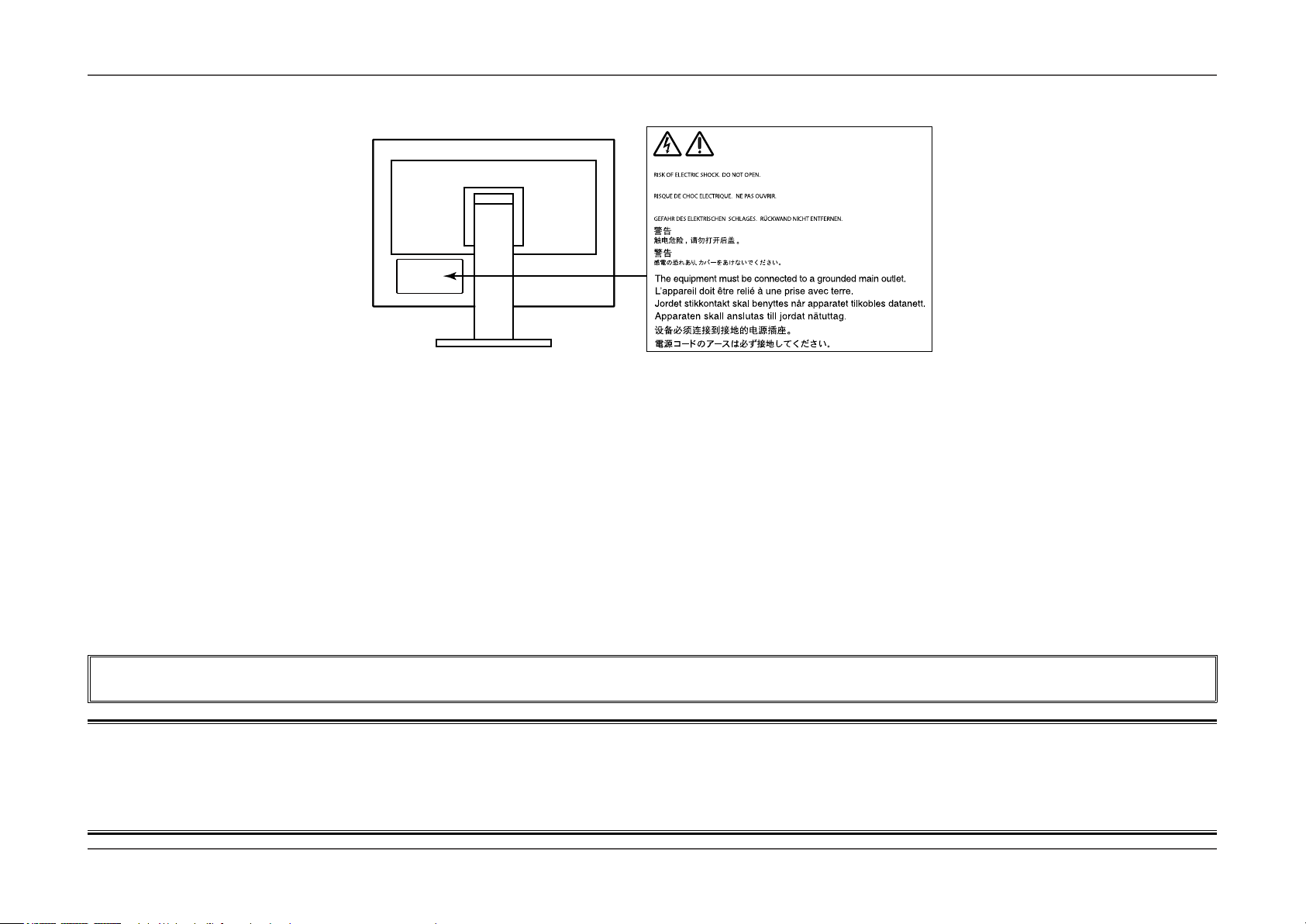
Location of Caution Statement
WARNING
AVERTISSEMENT
WARNUNG
This product has been adjusted specically for use in the region to which it was originally shipped. If operated outside this region, the product may not perform as
stated in the specications.
No part of this manual may be reproduced, stored in a retrieval system, or transmitted, in any form or by any means, electronic, mechanical, or otherwise, without
the prior written permission of EIZO Corporation.
EIZO Corporation is under no obligation to hold any submitted material or information condential unless prior arrangements are made pursuant to EIZO
Corporation’s receipt of said information. Although every eort has been made to ensure that this manual provides up-to-date information, please note that EIZO
monitor specications are subject to change without notice.
- 2 -
Page 3
Notice for this monitor
Notice for this monitor
Aside from general purposes like creating documents, viewing multimedia content, this product is also suited to applications such as graphics creation and digital
photo processing, where accurate color reproduction is a priority.
This product has been adjusted specically for use in the region to which it was originally shipped. If the product is used outside the region, it may not operate as
specied in the specications.
This product may not be covered by warranty for uses other than those described in this manual.
The specications noted in this manual are only applicable when the following are used:
· Power cords provided with the product
· Signal cables specied by us
Only use optional products manufactured or specied by us with this product.
If you place this product on a lacquer-coated desk, the color may adhere to the bottom of the stand due to the composition of the rubber. Check the desk surface
before use.
It takes about 30 minutes for the performance of electrical parts to stabilize. Please wait 30 minutes or more after the monitor power has been turned on, and then
adjust the monitor.
Monitors should be set to a lower brightness to reduce changes in luminosity caused by long-term use and maintain a stable display.
When the screen image is changed after displaying the same image for extended periods of time, an afterimage may appear. Use the screen saver or power save
function to avoid displaying the same image for extended periods of time.
If the monitor displays continuously over a long period of time, dark smudges or burn-in may appear. To maximize the life of the monitor, we recommend the monitor
be turned o periodically.
Periodic cleaning is recommended to keep the monitor looking new and to prolong its operation lifetime (refer to “Cleaning” (page 4)).
The LCD panel is manufactured using high-precision technology. Although, missing pixels or lit pixels may appear on the LCD panel, this is not a malfunction.
Percentage of eective dots: 99.9994% or higher.
- 3 -
Page 4
Notice for this monitor
The backlight of the LCD panel has a xed lifetime. When the screen becomes dark or begins to icker, please contact your local EIZO representative.
Do not press on the panel or edge of the frame strongly, as this may result in display malfunctions, such as interference patterns, etc. If pressure is continually
applied to the panel, it may deteriorate or damage your panel. (If the pressure marks remain on the panel, leave the monitor with a black or white screen. The
symptom may disappear.)
Do not scratch or press on the panel with any sharp objects, as this may result in damage to the panel. Do not attempt to brush with tissues as this may scratch the
panel.
When the monitor is cold and brought into a room or the room temperature goes up quickly, dew condensation may occur on the interior and exterior surfaces of the
monitor. In that case, do not turn the monitor on. Instead wait until the dew condensation disappears, otherwise it may cause some damage to the monitor.
Cleaning
Attention
• Chemicals such as alcohol and antiseptic solution may cause gloss variation, tarnishing, and fading of the cabinet or panel, and also quality deterioration of the image.
• Never use any thinner, benzene, wax, and abrasive cleaner, which may damage the cabinet or panel.
Note
• The optional ScreenCleaner is recommended for cleaning the cabinet and panel surface.
The stains on the cabinet and panel surface can be removed by moistening part of a soft cloth with water.
To use the monitor comfortably
• An excessively dark or bright screen may aect your eyes. Adjust the brightness of the monitor according to the environmental conditions.
• Staring at the monitor for a long time tires your eyes. Take a 10-minute rest every hour.
- 4 -
Page 5

Contents
Contents
Notice for this monitor .................................................................................3
Cleaning .................................................................................................................4
To use the monitor comfortably ..........................................................................4
Contents ........................................................................................................ 5
Chapter 1 Introduction ................................................................................ 7
1-1. Features......................................................................................................7
1-2. Controls and Functions ............................................................................9
●Front ............................................................................................................9
●Rear ...........................................................................................................10
1-3. Supported Resolutions ........................................................................... 11
●When using digital signal input (DVI-D, DisplayPort, HDMI: PC signal) ....11
*2
●When using digital signal input (HDMI: Video signal
1-4. Changing the PC Display Settings .........................................................12
●Windows 10 ...............................................................................................12
●Windows 8.1 / Windows 7 .......................................................................13
●macOS ......................................................................................................13
) .............................12
Chapter 2 Basic Adjustments/Settings .................................................... 14
2-1. Switch Operation Method .......................................................................14
2-2. Switching Input Signals ..........................................................................15
2-3. Switching the display mode (color mode) ............................................16
●Display Modes ...........................................................................................16
Chapter 3 Advanced Adjustments/Settings ............................................ 17
3-2. Setting Menu Functions ..........................................................................18
●Color ..........................................................................................................18
●Signal Settings...........................................................................................21
●Preferences ...............................................................................................24
●Languages .................................................................................................26
●Information.................................................................................................26
Chapter 4 Administrator Settings ............................................................ 27
4-1. Basic Operation of the “Administrator Settings” menu ......................27
4-2. “Administrator Settings” Menu Functions ............................................28
Chapter 5 Troubleshooting ....................................................................... 29
5-1. No picture .................................................................................................29
5-2. Imaging problems....................................................................................30
5-3. Other problems ........................................................................................31
Chapter 6 Reference ..................................................................................32
6-1. Removing the Stand ................................................................................32
6-2. Attaching the Optional Arm ....................................................................33
6-3. Detaching/Attaching Stand Base ...........................................................36
6-4. Attaching/Detaching Cable Holder ........................................................39
6-5. Connecting Multiple External Devices ..................................................41
6-6. Making Use of USB (Universal Serial Bus) ...........................................42
●Required System Environment ..................................................................42
●Connection Procedure (Setup of USB Function) .......................................43
3-1. Basic Operation of the Setting menu ....................................................17
6-7. Specications ..........................................................................................44
- 5 -
Page 6
●Dimensions ................................................................................................46
●Main Default Settings ................................................................................47
●Accessories ...............................................................................................47
Chapter 7 Glossary.....................................................................................48
Appendix .....................................................................................................50
Trademark ............................................................................................................50
License ................................................................................................................50
FCC Declaration of Conformity .........................................................................51
Contents
- 6 -
Page 7
Chapter 1 Introduction
Thank you very much for choosing an EIZO color LCD monitor.
1-1. Features
• 24.0″ widescreen
• Wide color gamut display (Adobe® RGB coverage: 99%)
• Supports a resolution of 1920 × 1200
• IPS panel with 89˚ horizontal and vertical wide viewing angles
• Frame synchronization mode supported (23.75 – 30.5 Hz, 47.5 – 61.0 Hz)
• Support for three digital signal inputs (DVI-D × 1, HDMI × 1, DisplayPort × 1)
- DisplayPort connector (applicable to 8 bit and 10 bit)
- HDMI connector (applicable to 8 bit, 10 bit, and 12 bit)
Can handle PC signals in HDMI input
*1 Not applicable to audio signals.
*2 10 bit and 12 bit are supported only when using HDMI-Video. The maximum screen display is 10 bits.
• Color mode function
Reproduces a color temperature, gamma, and gamut compliant with the following standards.
- Adobe® RGB / sRGB
See “Chapter 3 Advanced Adjustments/Settings” (page 17)
• Stand with wide range of movement
The monitor can be adjusted to a position where it provides you with a comfortable and less tiring work environment.
(Tilt: up 35˚/down 5˚, Swivel: 344˚, Adjustable height: 145 mm (Tilt: 35°), 155 mm (Tilt: 0°))
• Supports portrait format
• Compatible with Color Management Software “ColorNavigator 7”, which enables you to calibrate monitor characteristics and generate color proles
• Equipped with a USB Hub function that supports USB 3.0
Achieves high-speed data transfers of up to 5 Gbps, which enables transfers of large amounts of data to and from USB-connected devices in a short amount time.
Also, the “CHARGE” USB downstream port supports quick charging, so you can recharge your smartphone or tablet in a short period of time.
See “6-5. Connecting Multiple External Devices” (page 41) and “USB CHARGE Port” (page 25)
• Displays HDCP (High Bandwidth Digital Protection) protected contents
Chapter 1
*1
*1,*2
Introduction
- 7 -
Page 8
Chapter 1
Note
• This monitor supports portrait format. When using the screen in a portrait position, you can change the orientation of the Setting menu. (see “Menu Rotation” (page 24))
• When using the monitor screen in a portrait position, the graphics board supporting portrait display is required. When placing the monitor in a portrait position, the settings of
your graphics board need to be changed. Refer to the User’s Manual of the graphics board for details.
Introduction
- 8 -
Page 9
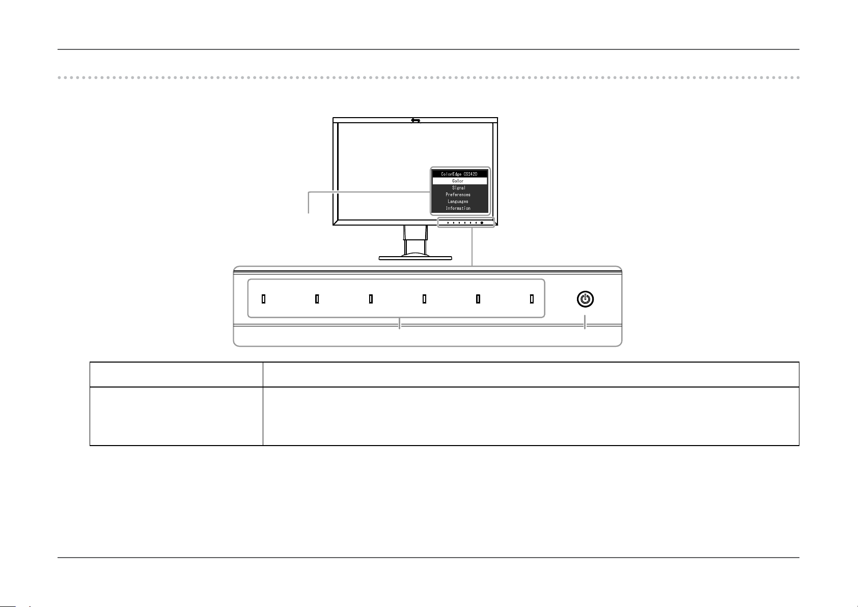
1-2. Controls and Functions
2
1
●Front
Chapter 1
Introduction
Setting menu
1. Operation switches Displays menus. Operate the switches according to the operation guide.
The switch indicator is lit white when you turn the power on.
2. Power switch Turns the power on or o.
The switch indicator is lit when you turn the power on. The indicator color diers depending on the monitor's operation status.
White: Operating
Orange: Power saving mode
OFF: Power o
*1 See “3-1. Basic Operation of the Setting menu” (page 17) for how to use.
*1
- 9 -
Page 10
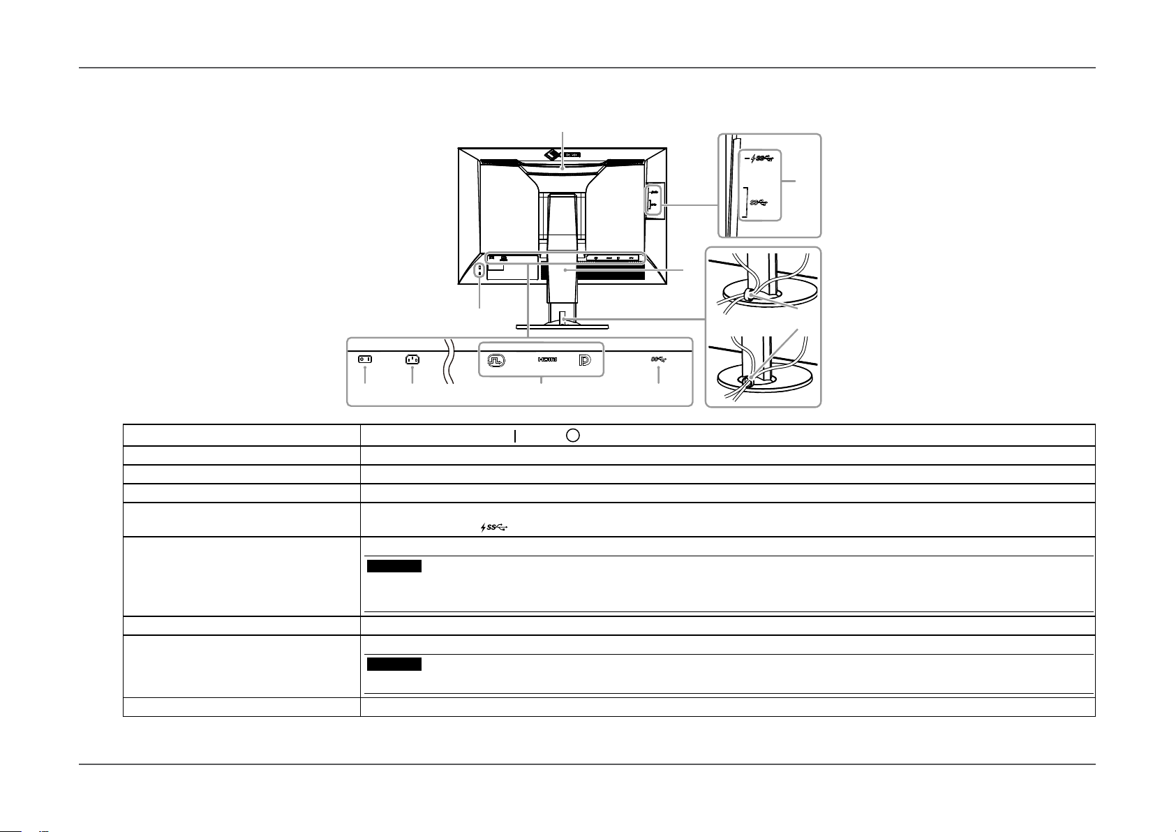
●Rear
Chapter 1
Introduction
8
7
10
9
43
3. Main power switch
4. Power connector Connects the power cord.
5. Input signal connectors Left: DVI-D connector / Center: HDMI connector / Right: DisplayPort connector
6. USB upstream port Connects to the USB cable when using software that requires a USB connection, or when using the USB Hub function (page 42).
7. USB downstream port Connects to a peripheral USB device.
8. Handle This handle is used for transportation.
9. Security lock slot Complies with Kensington’s MicroSaver security system.
10. Stand
11. Cable holder
*2 An optional arm (or an optional stand) can be attached by removing the stand section (see “6-1. Removing the Stand” (page 32)).
*3 For details on mounting the cable holder, see “6-4. Attaching/Detaching Cable Holder” (page 39).
*2
*3
Turns the main power on (
The “CHARGE” port
Attention
• Firmly grasp and hold the monitor by the bottom while grabbing the handle, and carefully convey the monitor so as not to drop it.
Do not hold the sensor section on the front side of the monitor.
Adjusts the height and angle (tilt and swivel) of the monitor.
Attention
• Do not hold the sensor section on the front side of the monitor.
Covers the monitor cables.
) or o ( ).
supports quick recharging (page 25).
65
11
- 10 -
Page 11
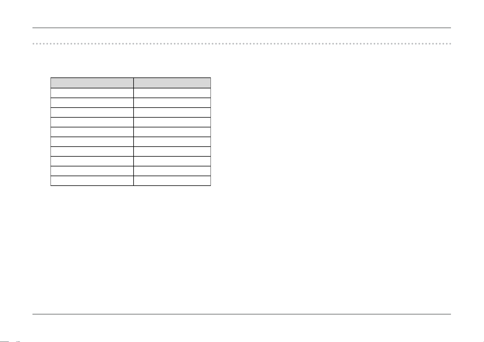
1-3. Supported Resolutions
The monitor supports the following resolutions.
●When using digital signal input (DVI-D, DisplayPort, HDMI: PC signal)
Resolution Vertical scan frequency
640 x 480 60 Hz
720 x 400 70 Hz
800 x 600 60 Hz
1024 x 768 60 Hz
1280 x 960 60 Hz
1280 x 1024 60 Hz
1600 x 1200 60 Hz
1680 x 1050 60 Hz
1920 x 1080 60 Hz
1920 x 1200
*1 Recommended resolution
*1
60 Hz
Chapter 1
Introduction
- 11 -
Page 12
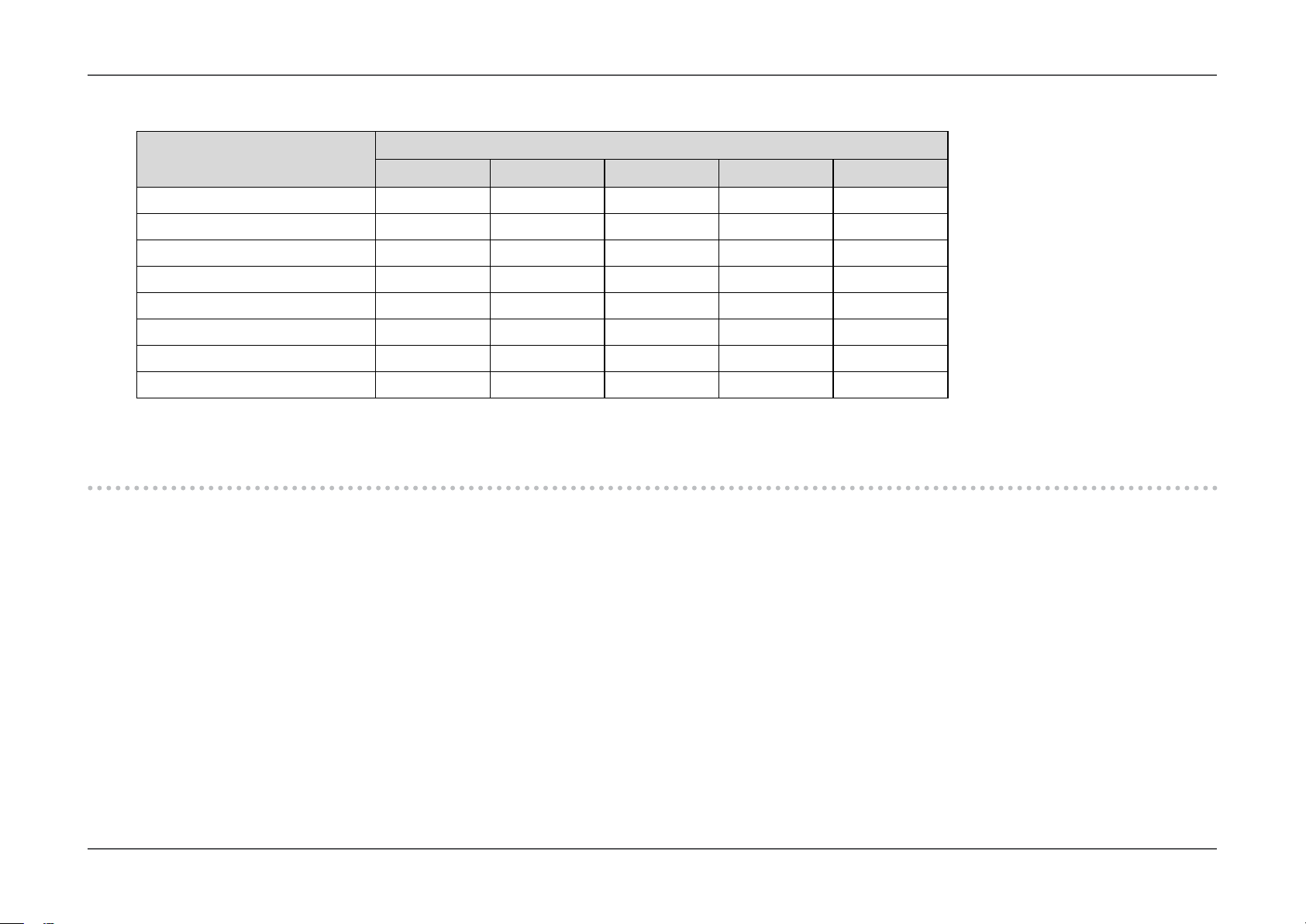
●When using digital signal input (HDMI: Video signal*2)
Chapter 1
Introduction
Resolution
24Hz 25Hz 30Hz 50Hz 60Hz
640 x 480 - - - - √
720 × 480 (480i) - - - - √
720 × 480 (480p) - - - - √
720 × 576 (576i) - - - √ -
720 × 576 (576p) - - - √ -
1280 × 720 (720p) - - - √ √
1920 × 1080 (1080i) - - - √ √
1920 × 1080 (1080p) √ √ √ √ √
*2 To display video signals by HDMI signal input, you must change the monitor settings beforehand.
Vertical scan frequency
1-4. Changing the PC Display Settings
If the screen is not properly displayed after connecting the monitor to a PC, follow the procedure below to change the PC display settings.
●Windows 10
1. Right-click anywhere on the desktop except for on icons to display the menu.
2. From the displayed menu, click “Display settings” to display the “Settings” screen.
3. If there are multiple monitors including the notebook PC screen connected to the computer, select “Extend these displays” from the “Multiple displays”
menu, and click “Keep changes” in the conrmation screen. After changing the settings, select the monitor from the “Select and arrange display” menu.
4. By checking the option “Make this my main display” from the “Multiple displays” menu, the display of the monitor will be corrected.
5. Conrm that the monitor’s recommended resolution is set in the “Resolution” menu (the term (Recommended) should be displayed after the resolution).
6. To change the size of letters and icons, select the preferred magnication level from the scaling (%) menu.
7. When after changing these settings a message is displayed that prompts you to sign out, sign out once and then sign in again.
- 12 -
Page 13

Chapter 1
Introduction
●Windows 8.1 / Windows 7
* For Windows 8.1, click the “Desktop” tile on the Start Screen to display the desktop.
1. Right-click anywhere on the desktop except for on icons to display the menu.
2. From the displayed menu, click “Screen resolution” to display the settings screen.
3. If there are multiple monitors including the notebook PC screen connected to the computer, select “Extend these displays” from the “Multiple displays”
menu, and click “Apply”. In the conrmation screen, click “Keep changes”.
4. Select the monitor from the “Display” menu, check the option “Make this my main display”, and click “Apply”. The display of the monitor will be corrected.
5. Conrm that the monitor’s recommended resolution is set in the “Resolution” menu (the term (Recommended) should be displayed after the resolution).
6. To change the size of letters and icons, click “Make text and other items larger or smaller”, select the preferred size from the settings screen, and click “Apply”.
7. When after changing settings a message is displayed that prompts you to sign out or log o, sign out or log o once and then sign in or log on again.
●macOS
1. Select “System Preferences” from the Apple menu.
2. When the “System Preferences” panel is displayed, click “Displays”.
3. If there are multiple monitors including the notebook PC screen connected to the computer, open the “Arrangement” tab and conrm that “Mirror displays”
is not selected. If it is selected, clear it.
4. Select the “Display” tab, and conrm that “Default for display” of “Resolution” is selected. If it is not selected, select it. This sets the correct resolution.
Close the “System Preferences” menu. If there are multiple monitors including the notebook PC screen connected to the computer, change the settings for
each monitor by using “Display”.
5. To select a dierent resolution, select “Scaled”, select a resolution from the resolution list (displayed in list or icon format), and close the panel.
- 13 -
Page 14
Chapter 2
Chapter 2 Basic Adjustments/Settings
This chapter describes the basic functions that can be adjusted and set by touching the switches on the front of the monitor.
For advanced adjustment and setting procedures using the Setting menu, see “Chapter 3 Advanced Adjustments/Settings” (page 17).
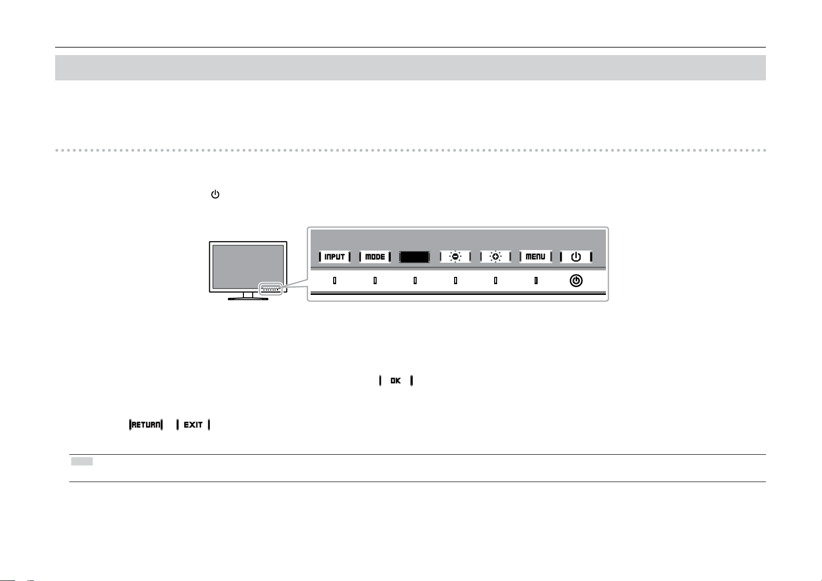
2-1. Switch Operation Method
Displaying the operation guide
1.
1. Touch any switch (except ).
The operation guide appears on the screen.
Basic Adjustments/Settings
Adjusting/setting
2.
1. Touch a switch for adjustment/setting.
The Adjustment/Setting menu appears.
2. Use the switches to adjust/set the selected item, and then select to conrm.
Exiting
3.
1. Select or to exit the menu.
2. When no menu is displayed, the operation guide will automatically disappear after a few seconds if no switches are operated.
Note
• The contents of the guide will dier depending on the selected menu or status.
- 14 -
Page 15
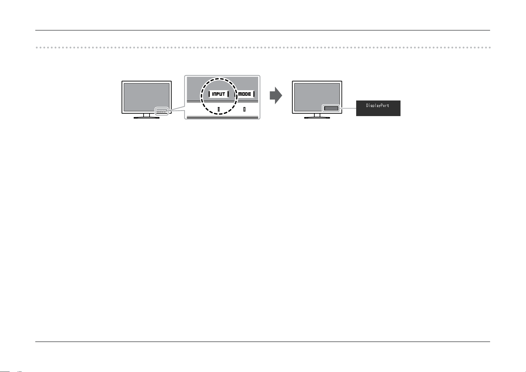
2-2. Switching Input Signals
When a monitor has multiple signal inputs, the signal to display on-screen can be changed.
When the input signal is switched, the connector name of the displayed signal appears at the bottom right of the screen.
Chapter 2
Basic Adjustments/Settings
- 15 -
Page 16

2-3. Switching the display mode (color mode)
This function allows easy selection of a display mode according to monitor application.
●Display Modes
Color Mode Purpose
Standard Mode Adjust color using the Color Management Software “ColorNavigator 7” or the monitor’s Setting menu.
Custom Select for conguring color settings according to your preference.
®
Adobe
sRGB Suitable for color matching with sRGB compatible peripherals.
Advanced Mode (CAL mode) Adjusts the monitor’s color using the “ColorNavigator 7” color management software.
CAL1 Displays the screen adjusted by ColorNavigator 7.
CAL2
CAL3
RGB Suitable for color matching with Adobe®RGB compatible peripherals.
Chapter 2
Basic Adjustments/Settings
Note
• The Setting menu and the Mode names cannot be displayed at the same time.
• You can disable specic mode selections. For more information, see “Mode Skip” (page 25).
• In the default settings, available Advanced Mode (CAL modes) dier depending on each input signal.
- CAL1 : DVI
- CAL2 : DisplayPort
- CAL3 : HDMI
- 16 -
Page 17

Chapter 3
Advanced Adjustments/Settings
Chapter 3 Advanced Adjustments/Settings
This chapter describes the advanced monitor adjustment and setting procedures using the Setting menu.
For the basic adjustment/setting functions using the switches on the front of the monitor, see “Chapter 2 Basic Adjustments/Settings” (page 14).
3-1. Basic Operation of the Setting menu
Menu display
1.
1. Touch any switch (except ).
The operation guide appears.
2. Select .
The Setting menu appears.
Adjusting/setting
2.
1. Choose a menu to adjust/set with , and then select
.
The Sub menu appears.
2. Choose an item to adjust/set with , and then press
.
The Adjustment/Setting menu appears.
3. Adjust/set the selected item with , and then select
.
The Sub menu appears.
Selecting
and restore the state prior to making changes.
Exiting
3.
1. Select .
The Setting menu appears.
2. Select .
The Setting menu exits.
Note
• The contents of the guide will dier depending on the selected menu or status.
during adjustment/setting will cancel the adjustment/setting
- 17 -
Page 18

3-2. Setting Menu Functions
●Color
When the screen is displayed in Standard Mode (Custom / Adobe®RGB / sRGB), you can adjust the color settings of each color mode according to your
preference.
Attention
• The same image may be seen in dierent colors on multiple monitors due to their monitor-specic characteristics. Make ne color adjustment visually when matching colors
on multiple monitors.
Note
• Use the values shown in “K” and “%” as a guide only.
Chapter 3
Advanced Adjustments/Settings
Function Adjustable range Description Note
Color Mode Custom
Brightness 0% to 100% The screen brightness is adjusted by changing the brightness of
Temperature Native
®
Adobe
sRGB
CAL1
CAL2
CAL3
4000 K to 10000 K
Adobe
sRGB
RGB
®
RGB
Select the desired mode according to the monitor application. • For more information on how to switch modes,
the backlight (light source from the LCD back panel).
The color temperature can be adjusted.
The color temperature is used to express the hue of “White” or
“Black” by a numerical value. The value is expressed in degrees “K”
(Kelvin).
The screen becomes reddish at a low color temperature, and bluish at a high color temperature, like the ame temperature.
Specify color temperature in units of 100 K, or select a color
temperature that complies with each standard.
- 18 -
see “2-3. Switching the display mode (color
mode)” (page 16).
• If the entered value cannot be set, the value
will appear in magenta. In such a case,
change the value.
• When you select “Native”, the original color
of the monitor (Gain: 100% for each RGB)
is displayed.
• “Gain” allows you to perform more advanced
adjustment. When gain is changed, the color
temperature is changed to “User”.
• The gain preset values are set for each color
temperature setting value.
Page 19

Function Adjustable range Description Note
Gamma 1.6 to 2.7
Color Gamut Native
Advanced Settings
Hue -100 to 100 Adjust the hue. • Using this function may make some color
Saturation -100 to 100 Adjust the color saturation. • Using this function may make some color
Adobe
sRGB
Adobe
sRGB
®
®
RGB
RGB
Adjust the gamma.
The brightness of the monitor varies depending on the input
signal, however, the variation rate is not simply proportional to the
input signal. The control performed to keep the balance between
the input signal and the brightness of the monitor is called
“Gamma correction”.
You can set the gamma, or select the gamma curve dened by
each standard.
Set the color reproduction area (color gamut).
“Color gamut” is the range of colors that devices such as monitors,
digital cameras and printers can represent. Multiple standards are
dened.
Chapter 3
-
• When you select “Native”, the original color
gamut of the monitor is displayed.
• The method of displaying colors outside the
monitor’s displayable range within the dened
color gamut can be set. For more information,
see “Clipping” (page 20).
gradations unavailable for display.
gradations unavailable for display.
• The minimum value (-100) changes the
screen to monochrome.
Advanced Adjustments/Settings
- 19 -
Page 20

Function Adjustable range Description Note
Advanced Settings
Reset - Resets any color adjustments for the currently selected color
Clipping On
O
Gain 0% to 100% The brightness of each color component red, green, and blue is
6 Colors -100 to 100 The hue, saturation and lightness can each be adjusted for the
The method of displaying colors outside the monitor’s displayable
range within the color gamut specied in accordance with “Color
Gamut” (page 19) can be set.
• “On”
The range of colors that are
displayable on the monitor
will be accurately displayed in
accordance with the standard.
Colors outside the displayable
range will be saturated.
• “O”
Displays colors with priority on
the color gradation rather than
the color accuracy. The vertices of the color gamut dened
in the standard move to a
range that can be displayed
by the monitor. This allows the
closest colors displayable by
the monitor to be displayed.
Color gamut displayable by the monitor
Color gamut defined by standard
Color gamut displayed on screen
called Gain. The hue of “white” can be changed by adjusting the
gain.
colors Magenta, Red, Yellow, Green, Cyan, and Blue.
mode back to the default settings.
Chapter 3
• The diagrams on the left are conceptual
diagrams, and do not display the actual color
gamut of the monitor.
• This setting will be disabled if “Native” is
selected at “Color Gamut” (page 19).
• Using this function may make some color
gradations unavailable for display.
• The gain value changes according to the color
temperature.
• When gain is changed, the color temperature
is changed to “User”.
-
-
Advanced Adjustments/Settings
- 20 -
Page 21

Chapter 3
●Signal Settings
The signal settings are used to congure advanced settings for input signals, such as the screen display size and color format.
Advanced Adjustments/Settings
- 21 -
Page 22

Function
Input Signal
(The setting range of each function
differs depending
on the input signal.)
√: Settable -: Not settable
Adjustable
range
Chapter 3
Advanced Adjustments/Settings
Description Note
DVI
Picture Expansion √ √ √ Auto
Input Color Format -
(Fixed
RGB)
*1 Only enabled when input signal information for automatically determining the setting is detected during HDMI input
*2 Only enabled when input signal information for automatically determining the setting is detected
DisplayPort HDMI
√ √ Auto
*1
Full Screen
Aspect Ratio
Dot by Dot
*2
YUV 4:2:2
YUV 4:4:4
RGB
The screen size of the monitor display can be changed.
• “Auto”
The monitor automatically changes the screen size
according to the resolution information and aspect ratio
information sent from the input signal.
• “Full Screen”
Displays an image in full screen. Images are distorted in
some cases because the vertical rate is not equal to the
horizontal rate.
When using video signal (480p/i, 576p/i) input, the image
will be displayed in full screen while maintaining the 16:9
aspect ratio.
• “Aspect Ratio”
Displays an image in full screen. However, since aspect
ratios are maintained, part of an image may not be visible
in horizontal or vertical direction.
When using video signal (480p/i, 576p/i) input, the image
will be displayed in full screen while maintaining the 4:3
aspect ratio.
• “Dot by Dot”
Displays the image at the set resolution or at the size
specied by the input signal.
The color space of the input signal can be specied.
Try changing this setting if colors are not displayed correctly.
• Example settings
- Full Screen
- Aspect Ratio
- Dot by Dot (input signal)
-
- 22 -
Page 23

Function
Input Signal
(The setting range of each function
differs depending
on the input signal.)
√: Settable -: Not settable
Adjustable
range
Chapter 3
Advanced Adjustments/Settings
Description Note
DVI
Input Range √ √ √ Auto
Noise Reduction - - √ On
*3 Only enabled during DisplayPort input or HDMI input
DisplayPort HDMI
Full
Limited
(109% White)
Limited
O
*3
Depending on the external device, the black and white levels
in the video signal output to the monitor may be restricted. If
the signal is displayed on the monitor in its restricted form, the
blacks will be faint, the whites dull, and contrast will be reduced. The brightness range of such signals can be extended
to match the actual contrast ratio of the monitor.
• “Auto”
The monitor automatically recognizes the brightness
range of input signals and displays images appropriately.
• “Full”
The input signal brightness range is not extended.
• “Limited (109% White)”
The brightness range of the input signal is extended from
64 - 1019 to 0 - 1023 for display.
• “Limited”
The brightness range of the input signal is extended from
64 - 940 to 0 - 1023 for display.
The small noises that occur in dark areas of an image are
reduced. Use this function to reduce noise and roughness in
images.
-
• Using the Noise Reduction
function may lead to deterioration of ne images.
- 23 -
Page 24

●Preferences
The monitor’s settings can be congured to suit the usage environment or personal preference.
Function Adjustable range Description Note
Auto Input Detection On
O
Menu Rotation 0°
90°
When this function is set to “On”, the monitor automatically recognizes the connector through which signals are input, so that
the screen can be displayed. When an external device enters the
power saving mode, the monitor automatically displays another
signal.
When set to “O”, the monitor displays the signal from the selected connector regardless of whether a signal is input or not. In this
case, select the input signal to display using the operation switch
(
This function allows you to change the orientation of the Setting
menu to align with the installation orientation.
) on the front of the monitor.
Chapter 3
• When the main power is turned on/o, the
signal is detected automatically regardless of
the setting for this function.
• Be sure that the cables are correctly
connected.
• When using the monitor screen in a portrait
position, the graphics board supporting
portrait display is required. When placing the
monitor in a portrait position, settings of your
graphics board need to be changed. Refer to
the User’s Manual of the graphics board for
details. Also, visit the EIZO website
(www.eizoglobal.com).
• When using the monitor in a portrait position,
rotate the monitor after pulling up the screen to
the uppermost position of the stand and setting
the screen tilted upward.
Advanced Adjustments/Settings
- 24 -
Page 25

Function Adjustable range Description Note
USB CHARGE Port Normal
Charging Only
Power Save On
O
Indicator O / 1 to 7 The brightness of the power switch and the operation switches
Beep On
O
Input Skip Skip / - This function allows skipping of input signals that will not be used
Mode Skip Skip / - This function allows skipping of modes that will not be used when
Monitor Reset - Restore all settings to their default values except for the following
The “CHARGE” USB downstream port of the monitor supports
USB 3.0 quick charging. By changing this setting to “Charging
Only”, devices connected to the “CHARGE” port can be charged
more quickly than when using the “Normal” setting.
This function allows you to set the monitor to the power saving
mode, depending on the state of an external device connected
to it.
The monitor changes to power saving mode about 15 seconds
after signal input ceases to be detected. When the monitor has
shifted to power saving mode, images are not displayed on the
screen.
• Exiting power saving mode
- If the monitor receives input, it automatically exits power
saving mode and returns to the normal display mode.
when the screen is displayed can be set. (Default setting: 4)
You can turn o the beep that sounds each time a switch is
operated.
when the input signals are switched.
selecting modes. Please use this function if display modes are
limited, or if you want to prevent randomly changing the display
status.
settings.
• Settings in the “Administrator Settings” menu
Chapter 3
• Make sure to complete any communication
between connected USB devices and the PC
before switching this setting. When the setting
is switched, all communication will be temporarily interrupted.
• Devices that are connected to the “CHARGE”
port must support quick charging.
• When “Charging Only” is set, data communications between the PC and connected devices
via the “CHARGE” port are not possible, and
therefore, connected devices will not work.
• When “Charging Only” is set, charging is possible even when the monitor and PC are not
connected by USB cable.
• At the time of shifting to power saving mode,
a message that indicates the transition is
displayed 5 seconds in advance.
• When not using the monitor, you can turn o
the main power supply so that the power is cut
completely.
• When the monitor is in power saving mode,
devices connected to the USB downstream
port will still work. Therefore, power consumption of the monitor varies even in the power
saving mode, depending on the connected
devices.
-
-
• Set at least one mode to “-”.
• Not all modes can be set to “Skip”.
• In the default settings, available Advanced
modes (CAL modes) dier depending on each
input signal.
• Regarding the default setting, see
“Main Default Settings” (page 47).
Advanced Adjustments/Settings
- 25 -
Page 26

Chapter 3
Advanced Adjustments/Settings
●Languages
The display language for menus and messages can be selected.
Adjustable range
English, Deutsch, Français, Español, Italiano, Svenska, Japanese, Simplied Chinese, Traditional Chinese
●Information
You can check the monitor information (model name, serial number, rmware version, usage time, ColorNavigator license status, resolution, input signal, etc.).
Example:
- 26 -
Page 27

Chapter 4 Administrator Settings
This chapter describes how to congure monitor operation using the “Administrator Settings” menu.
This menu is for administrators. Conguration on this menu is not required for normal monitor use.
4-1. Basic Operation of the “Administrator Settings” menu
Chapter 4
Administrator Settings
Menu display
1.
1. Touch to turn o the monitor.
2. While touching the leftmost switch, touch
to turn on the monitor.
The “Administrator Settings” menu appears.
for more than 2 seconds
Settings
2.
1. Choose an item to set with , and then select .
The Adjustment/Setting menu appears.
2. Set the item with , and then select .
The “Administrator Settings” menu appears.
Applying and exiting
3.
1. Select “Apply”, and then select .
The settings are conrmed and the “Administrator Settings” menu quits.
- 27 -
Page 28

4-2. “Administrator Settings” Menu Functions
Function Adjustable Range Description Note
On-Screen Logo On
O
Key Lock O
Menu
All
DP Power Save On
O
DUE Priority Brightness
Uniformity
Signal Format DisplayPort RGB
RGB/YUV
HDMI Video
PC
When the monitor is turned on, the EIZO logo appears on the screen.
When this function is set to “O”, the EIZO logo does not appear.
In order to prevent changes to settings, the operation switches on the
front of the monitor can be locked.
• “O” (Default setting)
Enable all switches.
• “Menu”
Lock the
• “All”
Lock all switches except the power switch.
If the PC is connected to the DisplayPort connector, and when the
power is turned on or o or when the monitor recovers from power
saving mode, window or icon positions may be shifted. If that occurs,
set this function to “O”.
This product is equipped with a Digital Uniformity Equalizer (DUE)
function that reduces display unevenness. This DUE setting can be
changed.
• “Brightness”
Prioritizes high brightness and high contrast.
• “Uniformity”
Prioritizes reduction of display unevenness.
You can switch the signal type that the monitor can display.
To display video signals when using HDMI signal input, set to “Video”.
switch.
Chapter 4
-
-
-
• When changing the DUE setting, the
monitor whose display is adjusted must be
re-calibrated. Perform the target calibration again using ColorNavigator 7. For details, refer to the ColorNavigator 7 User's
Manual.
-
Administrator Settings
- 28 -
Page 29

Chapter 5
Troubleshooting
Chapter 5 Troubleshooting
If a problem still remains after applying the suggested remedies, contact your local EIZO representative.
5-1. No picture
Problem Possible cause and remedy
1. No picture
• Power indicator does not light up.
• Power indicator is lighting white. • Increase “Brightness” and/or “Gain” in the Setting menu. (See “Color” (page 18))
• Power indicator is lighting orange. • Switch the input signal.
• Power indicator is ashing orange and white. • This problem may occur when a PC is connected via the DisplayPort connector. Connect with the signal cable specied
2. The message below appears. This message appears when the signal is not input correctly even though the monitor is functioning properly.
• This message appears when no signal is input.
Example:
• Check whether the power cord is connected properly.
• Turn on the main power switch on the rear side of the monitor.
• Touch
• Turn o the main power on the rear side of the monitor, and then turn it on again a few minutes later.
• Move the mouse or press any key on the keyboard.
• Check whether the PC is turned on.
• Turn o the main power on the rear side of the monitor, and then turn it on again.
by EIZO, turn o the monitor, and then turn it on again.
• The message shown left may appear, because some PCs do not output the signal immediately after power-on.
• Check whether the PC is turned on.
• Check whether the signal cable is connected properly.
• Switch the input signal.
• Turn o the main power on the rear side of the monitor, and then turn it on again.
.
• The message shows that the input signal is out
of the specied frequency range.
Example:
• Check whether the PC is congured to meet the resolution and vertical scan frequency requirements of the monitor
(see “1-3. Supported Resolutions” (page 11)).
• Reboot the PC.
• Change to the appropriate setting using the graphics board's utility. Refer to the User's Manual of the graphics board for
details.
- 29 -
Page 30

Chapter 5
Troubleshooting
5-2. Imaging problems
Problem Possible cause and remedy
1. The screen is too bright or too dark. • Use “Brightness” in the Setting menu to adjust it (see “Information” (page 26)). (The LCD monitor backlight has a lim-
ited life span. When the screen becomes dark or begins to icker, contact your local EIZO representative.)
2. Afterimages appear • Afterimages are particular to LCD monitors. Avoid displaying the same image for a long time.
• Use the screen saver or power saving function to avoid displaying the same image for extended periods of time.
3. Green/red/blue/white dots or defective dots
remain on the screen.
4. Interference patterns or pressure marks
remain on the screen.
5. Noise appears on the screen. • When inputting HDCP system signals, normal images may not be displayed immediately.
6. (DisplayPort signal input)
When you switch the power back on or
return from power save mode, windows or
icons may have shifted position.
7. (DisplayPort or HDMI input)
The color shown on the screen is not cor-
rect.
8. The image does not display on the entire
screen.
• This is due to LCD panel characteristics and not a malfunction.
• Display a white or black image over the entire screen. The symptom may disappear.
• In the Setting menu, set “DP Power Save” to “O” (see “DP Power Save” (page 28)).
• Try changing “Input Color Format” in the Setting menu (see “Input Color Format” (page 22)).
• For HDMI signal input, try changing “Signal Format” in the Setting menu (see “Signal Format” (page 28)).
• Try changing “Picture Expansion” in the Setting menu (see “Picture Expansion” (page 22)).
• For HDMI signal input, check whether “Signal Format” is set to “PC” in the Setting menu (see “Signal Format” (page
28)).
- 30 -
Page 31

5-3. Other problems
Problem Possible cause and remedy
1. The Setting menu/Mode menu cannot be
displayed
2. The monitor connected with the USB cable
is not detected. / USB device connected to
the monitor does not work.
3. Audio is not output. • This monitor does not support the HDMI/DisplayPort audio signals.
• Check whether the operation switch lock function works (see “Key Lock” (page 28)).
• Operation switches are locked when the main window of ColorNavigator 7 is displayed.
• Check whether the USB cable is connected correctly (see “6-5. Connecting Multiple External Devices” (page 41)).
• If a peripheral device is connected to the “CHARGE” port, try checking the “USB CHARGE Port” setting
(see “USB CHARGE Port” (page 25)). If it is set to “Charging Only”, the peripheral device will not work.
• Try changing to a dierent USB port on the PC.
• Try changing to a dierent USB port on the monitor.
• Reboot the PC.
• If the peripheral devices work correctly when the PC and peripheral devices are connected directly, contact your local
EIZO representative.
• Check whether the PC and OS are USB compliant. (For USB compliance of the respective devices, consult their manufacturers.)
• Depending on the USB 3.0 host controller that you are using, connected USB devices may not be recognized correctly.
Update to the latest USB 3.0 driver provided by each manufacturer, or connect the monitor to the USB 2.0 port.
• Check the PC’s BIOS setting for USB when using Windows. (Refer to the manual of the PC for details.)
Chapter 5
Troubleshooting
- 31 -
Page 32

Chapter 6 Reference
6-1. Removing the Stand
The stand section of this product can be removed.
Attention
• Do not move the removed stand up and down. Doing so may result in injury or equipment damage.
• The monitor and stand are heavy. Dropping them may result in injury or equipment damage.
To prevent damaging the panel surface, lay the monitor with its panel surface facing down on a soft cloth spread on a
1.
stable surface.
Remove the stand.
2.
Press and hold he lock button (1), rmly grip the stand support, and then slide the stand in the direction of the base of the stand (2).
When the tab that holds the stand in place loosens, remove the stand (3).
(3)
Chapter 6
Reference
(2)
- 32 -
(1)(1)
Page 33

Chapter 6
6-2. Attaching the Optional Arm
An optional arm (or an optional stand) can be attached by removing the stand section. Please refer to our web site for the corresponding optional arm
(or optional stand). www.eizoglobal.com
Attention
• When attaching an arm or stand, follow the instructions of their User's Manual.
• When using another manufacturer’s arm or stand, conrm the following in advance and select one conforming to the VESA standard. Use the VESA mounting screws supplied
with this product when attaching the arm or stand.
- Clearance between screw holes: 100 mm × 100 mm
- External dimensions of the VESA mount section of the arm or stand: 122 mm × 122 mm or less
- Plate thickness: 2.6 mm
- Must be strong enough to support weight of the monitor unit (excluding the stand) and attachments such as cables.
• When using an arm or stand, attach it to meet the following tilt angles of the monitor.
- Up 45˚, down 45˚
• Connect the cables after attaching an arm or stand.
• Do not move the removed stand up and down. Doing so may result in injury or equipment damage.
• The monitor, arm, and stand are heavy. Dropping them may result in injury or equipment damage.
• When installing the monitor in portrait mode, turn the monitor screen 90˚ in clockwise direction.
Reference
- 33 -
Page 34

Attaching the Optional Arm (or Optional Stand)
Attach the arm or stand to the monitor.
1.
Use the VESA mounting screws supplied with this product when attaching the arm or stand.
Chapter 6
Reference
- 34 -
Page 35

Chapter 6
Attaching the original stand
To prevent damaging the panel surface, lay the monitor with its panel surface facing down on a soft cloth spread on a
1.
stable surface.
Remove the xing screws on the optional arm (or optional stand), and detach the optional arm (or optional stand).
2.
Attach the original stand.
3.
Insert the four tabs on the stand into the square holes on the back panel (1) and slide the stand towards the upper portion of the monitor until it makes a
clicking sound (2).
(1)
(2)
(2)
Click!Click!
Reference
- 35 -
Page 36

6-3. Detaching/Attaching Stand Base
Detachment procedure
The stand base that was attached during setup can be detached using the following procedures.
Lay the LCD monitor on a soft cloth spread over on a stable surface with the panel surface facing down.
1.
Raise the lever on the bottom of the stand base.
2.
Chapter 6
Reference
Turn the stand base in the counterclockwise direction to detach it.
3.
- 36 -
Page 37

Attachment procedure
The once removed the stand base can be attached to the monitor again with the following procedures.
Lay the LCD monitor on a soft cloth spread over on a stable surface with the panel surface facing down.
1.
Attach the stand base onto the stand brace.
2.
Chapter 6
Reference
- 37 -
Page 38

Turn the stand base clockwise until it makes a clicking sound.
3.
Chapter 6
Reference
- 38 -
Click!
Page 39

6-4. Attaching/Detaching Cable Holder
A cable holder is supplied with this product. Use the cable holder to organize the cables connected to the monitor.
Attachment procedure
Pass the cables through the cable holder.
1.
Close the cable holder.
2.
Chapter 6
Reference
While holding the cable holder closed, insert it into the stand.
3.
- 39 -
Page 40

Chapter 6
Note
• The cable holder can be inserted either perpendicular or parallel to the stand. Change the orientation of the cable holder in line with the direction of the cables.
Detachment procedure
Close the cable holder.
1.
While holding the cable holder closed, pull it from the stand.
2.
Reference
- 40 -
Page 41

6-5. Connecting Multiple External Devices
The product allows you to connect multiple external devices and switch between them for display.
Connection
examples
Chapter 6
Note
Reference
• The input signal changes each time the
operation switch ( ) on the front of
the monitor is touched. When the signal is
switched, the active input connector name
appears at the lower right corner of the
screen.
• This product automatically recognizes the
connector through which signals are input
and displays images on the screen accordingly. For more information, see
“Auto Input Detection” (page 24).
Digital
(DVI)
Signal cable
FD-C39
(optional)
DVI connector
To PC 1 To PC 2 To PC 3
HDMI connector
Digital
(HDMI)
Signal cable
HH200HS
DisplayPort connector
- 41 -
Digital
(DisplayPort)
Signal cable
PP200
Page 42

Chapter 6
Reference
6-6. Making Use of USB (Universal Serial Bus)
This monitor is equipped with a USB hub. It works as a USB hub when connected to a USB-compatible PC, allowing the connection of peripheral USB devices.
Note
• This product supports USB 3.0. When connecting peripheral devices that support USB 3.0, high-speed data communication is possible (however, only when the USB cable used
to connect the PC and peripheral device is USB 3.0 compliant).
• The “CHARGE” USB downstream port also supports quick charging. This allows you to recharge your smartphone or tablet in a short period of time. (See “USB CHARGE Port”
(page 25).)
●Required System Environment
• A PC equipped with a USB port
• Windows 10 / Windows 8.1 / Windows 8 / Windows 7, or Mac OS X 10.7.5 or later
• EIZO USB cable (UU200SS (USB 3.0))
Attention
• This monitor may not work depending on the used PC, OS or peripheral devices. For USB compatibility of peripheral devices, contact their manufactures.
• When the monitor is in power saving mode, devices connected to the USB downstream port will still work. Therefore, power consumption of the monitor varies depending on
the connected devices, even in the power saving mode.
• When the main power of the monitor is o, a device connected to the USB downstream port will not operate.
• When the “USB CHARGE Port” setting in “Preferences” is set to “Charging Only”, a peripheral device will not work if connected to the “CHARGE” port.
• Ensure that communication between all peripheral devices connected to the monitor and the PC is ended before switching the “USB CHARGE Port” setting. When the
setting is switched, all communication will be temporarily interrupted.
- 42 -
Page 43

●Connection Procedure (Setup of USB Function)
1. Connect the monitor rst to a PC using the signal cable, and start the PC.
2. Connect the USB cable between the USB downstream port of the PC and the USB upstream port of the monitor.
The USB hub function is set up automatically upon connection of the USB cable.
3. Connect the peripheral USB device to the USB downstream port of the monitor.
“CHARGE” port
Chapter 6
Reference
USB upstream
port
USB
downstream
port
- 43 -
Page 44

6-7. Specications
LCD Panel Type IPS (Anti-Glare)
Backlight Wide color gamut LED
Size 61 cm (24.0inch)
Resolution 1920 dots × 1200 lines
Display Size (H × V) 518.4 mm × 324.0 mm
Pixel Pitch 0.270mm×0.270mm
Display Colors Approx. 1073.74 million colors (for 10 bit input)
Viewing Angle (H / V, typical) 178˚ / 178˚
2
Recommended Brightness (typical) 120 cd/m
Contrast Ratio (typical) 1000 : 1 (When “DUE Priority” setting is “Brightness”)
Response Time (typical) Black-white-black: 13 ms
Gray-to-gray: 15 ms
Color Gamut Display (typical) Adobe
Video Signals Input Terminals DVI-D x 1 (Single Link, applicable to HDCP)
HDMI x 1 (Applicable to HDCP)
DisplayPort x 1(Applicable to HDCP)
Horizontal scan frequency 26 kHz to 78 kHz (DVI, DisplayPort, HDMI PC)
15 kHz to 78 kHz (HDMI Video)
Vertical scan frequency 24 Hz to 61 Hz (720 x 400 : 69 Hz to71 Hz)
Frame Synchronization Mode 23.75 Hz to 30.5 Hz, 47.5 Hz to 61.0 Hz
Dot clock (Max.) 164 MHz
USB Port Upstream port × 1, downstream port × 3 (The “CHARGE” port supports quick recharging)
Standard USB Specication Rev. 3.0
USB Battery Charging Specication Rev.1.2
Communication Speed 5 Gbps (super), 480 Mbps (high), 12 Mbps (full), 1.5 Mbps (low)
Supply Current Downstream: Max. 900 mA per port
Downstream (CHARGE Port): Normal: Max. 1.5 A per port, Charging Only: Max. 2.1 A per port
Power Input 100–240 VAC ±10%, 50/60 Hz, 0.95 A–0.50 A)
Maximum Power Consumption 92 W or less
Power Save Mode 0.7 W or less (When DisplayPort 1 connector is input, “Auto Input Detection” is set to “O”, and no USB device is
Standby Mode 0.6 W or less (When “Auto Input Detection” is set to “O”, and no USB device is connected; or the USB CHARGE
or less (Temperature: 5000 K to 6500 K)
®
RGB coverage: 99%, NTSC ratio 110%
connected; or the USB CHARGE port is set to “Normal”, and the OS is in sleep mode; or when the
monitor’s power o setting is activated)
port is set to “Normal”, “DP Power Save” is set to “On”)
Chapter 6
Reference
- 44 -
Page 45

Chapter 6
Reference
Physical
Specications
Operating
Environment
Requirements
Transportation/
Storage Environment
Requirements
Dimensions Min. height:
Max. height:
Dimensions (Without Stand) 554.4 mm × 362 mm × 64 mm (W × H × D)
Net. weight Approx. 7.8 kg
Net Weight (Without Stand) Approx. 5.0 kg
Height adjustment 155 mm (Tilt: 0˚) / 145mm (Tilt: 35˚)
Tilt Up 35˚, down 5˚
Swivel 344°
Vertical Rotation Clockwise 90°
Temperature 0˚C to 35˚C (32˚F to 95˚F)
Humidity 20% to 80% R.H. (no condensation)
Air Pressure 540 hPa to 1060 hPa
Temperature -20 ˚C to 60 ˚C (-4 ˚F to 140 ˚F)
Humidity 10% to 90% R.H. (no condensation)
Air Pressure 200 hPa to 1060 hPa
554.4 mm × 396 mm × 245 mm (W × H × D) (Tilt: 0˚)
554.4 mm × 558 mm × 265 mm (W × H × D) (Tilt: 35˚)
- 45 -
Page 46

●Dimensions
245
325.4
VESA
Chapter 6
Reference
Unit: mm
344
°
554.4
519.8
90
°
35
5
°
145
64
30
265
°
362
565.4-647.2
396-551
155
558
413
61.3
133.7
35
°
5
°
100
VESA
122.6
341.5
(227.2)(227.2)
636.4
491.3
100
(131) (131)
34
- 46 -
11
62.7
Page 47

●Main Default Settings
Color Mode Custom
Picture Expansion DVI input Aspect Ratio
DisplayPort input Aspect Ratio
HDMI input Aspect Ratio (When “Auto” is enabled: Auto)
Input Color Format DisplayPort input Auto
HDMI input RGB (When “Auto” is enabled: Auto)
Input Range DVI input Full
DisplayPort input Auto
HDMI input Auto
Noise Reduction O
Auto Input Detection O
Menu Rotation 0°
USB CHARGE Port Normal
Power Save On
Indicator 4
Beep On
Language English
Logo On
Key Lock O
Signal Format DisplayPort RGB
HDMI PC
Chapter 6
Reference
●Accessories
For the latest information about the accessories, refer to our web site.
www.eizoglobal.com
- 47 -
Page 48

Chapter 7 Glossary
Adobe®RGB
This is a denition of the practical RGB color space proposed by Adobe Systems in 1998. The color reproduction range (color gamut) is broader than
sRGB, and is highly adaptable to such elds as printing etc.
Color Space
YUV and RGB, etc. are available. YUV expresses the color by using the luminance (Y), the color dierence of Blue (U), and the color dierence of Red (V).
RGB does this by using the gradation of the 3 colors, Red (R), Green (G), and Blue (B).
DisplayPort
This is the interface standard for image signals standardized in accordance with VESA. It was developed with the aim of replacing the conventional DVI
and analog interfaces, and it can transmit high resolution signals and sound signals, which DVI does not support. The standard size and mini size
connectors have been standardized.
DVI (Digital Visual Interface)
Chapter 7 Glossary
DVI is a digital interface standard. DVI allows direct transmission of the PC’s digital data without loss.
This adopts the TMDS transmission system and DVI connectors. There are two types of DVI connectors. One is a DVI-D connector for digital signal input
only. The other is a DVI-I connector for both digital and analog signal inputs.
Gain
The brightness of each color component red, green, and blue is called Gain. An LCD monitor displays the color by the light passing through the panel color
lter. Red, green and blue are the three primary colors. All the colors on the screen are displayed by combining these three colors. The color tone can be
changed by adjusting the light intensity (volume) passing through each color’s lter.
Gamma
Generally, the monitor brightness varies nonlinearly with the input signal level, which is called “Gamma Characteristic”. When the gamma value is low, the
middle tone area is displayed brighter, and darker when high. Changes to the gamma value will not aect contrast. A gamma value appropriate for the
display content should be selected.
- 48 -
Page 49

Chapter 7 Glossary
HDCP (High-bandwidth Digital Content Protection)
Digital signal coding system developed to copy-protect the digital contents, such as video, music, etc.
This helps to transmit the digital contents safely by coding the digital contents sent via the DVI or HDMI connector on the output side and decoding them
on the input side.
Any digital contents cannot be reproduced if both of the equipments on the output and input sides are not applicable to HDCP system.
HDMI (High-Denition Multimedia Interface)
HDMI is a digital interface standard, developed for consumer electrical appliance or AV device. This standard is issued on the basis of the DVI standard
which is one of an interface specication for the connection between a PC and a monitor. The projected image, sound and control signal without
compressed enable to be transmitted with one cable.
L*
L* is a lightness value based on the CIELUV and CIELAB color spaces. CIELUV and CIELAB are color spaces that describe the relationship between color
and human vision, in which L* corresponds to perceived brightness.
Resolution
The LCD panel consists of numerous pixels of specied size, which are illuminated to form images. This monitor consists of horizontal 1920 pixels and
1200 vertical pixels. At a resolution of 1920 × 1200, all pixels are illuminated as a full screen (1:1).
sRGB (Standard RGB)
International standard for color reproduction and color space among peripheral devices (such as monitors, printers, digital cameras, scanners). As a form
of simple color matching for the Internet, colors can be displayed using tones close to those of the transmission and reception devices.
Temperature
Color temperature is a method to measure the white color tone, generally indicated in degrees Kelvin. The screen becomes reddish at a low temperature,
and bluish at a high temperature, like the ame temperature.
5000 K: Slightly reddish white
6500 K: White referred to as daylight-balanced color
9300 K: Slightly bluish white
- 49 -
Page 50

Appendix
Trademark
The terms HDMI and HDMI High-Denition Multimedia Interface, and the HDMI Logo are trademarks or registered trademarks of HDMI Licensing, LLC in the
United States and other countries.
The DisplayPort Compliance Logo and VESA are registered trademarks of the Video Electronics Standards Association.
The SuperSpeed USB Trident Logo is a registered trademark of USB Implementers Forum, Inc.
The USB Power Delivery Trident Logos are trademarks of USB Implementers Forum, Inc.
DICOM is the registered trademark of the National Electrical Manufacturers Association for its standards publications relating to digital communications of
medical information.
Kensington and Microsaver are registered trademarks of ACCO Brands Corporation.
Thunderbolt is a trademark of Intel Corporation in the United States and/or other countries.
Microsoft and Windows are registered trademarks of Microsoft Corporation in the United States and other countries.
Adobe is a registered trademark of Adobe Systems Incorporated in the United States and other countries.
Apple, macOS, Mac OS, OS X, Macintosh and ColorSync are registered trademarks of Apple Inc.
EIZO, the EIZO Logo, ColorEdge, CuratOR, DuraVision, FlexScan, FORIS, RadiCS, RadiForce, RadiNET, Raptor and ScreenManager are registered
trademarks of EIZO Corporation in Japan and other countries.
ColorEdge Tablet Controller, ColorNavigator, EcoView NET, EIZO EasyPIX, EIZO Monitor Congurator, EIZO ScreenSlicer, G-Ignition, i•Sound, Quick Color
Match, RadiLight, Re/Vue, SafeGuard, Screen Administrator, Screen InStyle, ScreenCleaner and UniColor Pro are trademarks of EIZO Corporation.
All other company and product names are trademarks or registered trademarks of their respective owners.
Appendix
License
The bitmap font used for this product is designed by Ricoh Industrial Solutions Inc.
- 50 -
Page 51

Appendix
FCC Declaration of Conformity
For U.S.A. , Canada, etc. (rated 100-120 Vac) Only
FCC Declaration of Conformity
We, the Responsible Party EIZO Inc.
5710 Warland Drive, Cypress, CA 90630
Phone: (562) 431-5011
declare that the product Trade name: EIZO
Model: ColorEdge CS2420
is in conformity with Part 15 of the FCC Rules. Operation of this product is subject to the following two conditions: (1) this device may not cause
harmful interference, and (2) this device must accept any interference received, including interference that may cause undesired operation.
This equipment has been tested and found to comply with the limits for a Class B digital device, pursuant to Part 15 of the FCC Rules. These
limits are designed to provide reasonable protection against harmful interference in a residential installation. This equipment generates, uses,
and can radiate radio frequency energy and, if not installed and used in accordance with the instructions, may cause harmful interference to radio
communications. However, there is no guarantee that interference will not occur in a particular installation. If this equipment does cause harmful
interference to radio or television reception, which can be determined by turning the equipment o and on, the user is encouraged to try to correct
the interference by one or more of the following measures.
* Reorient or relocate the receiving antenna.
* Increase the separation between the equipment and receiver.
* Connect the equipment into an outlet on a circuit di erent from that to which the receiver is connected.
* Consult the dealer or an experienced radio/TV technician for help.
Changes or modi cations not expressly approved by the party responsible for compliance could void the user’s authority to operate the
equipment.
- 51 -
Page 52

Appendix
Note
Use the attached speci ed cable below or EIZO signal cable with this monitor so as to keep interference within the limits of a Class B digital device.
- AC Cord
- Shielded Signal Cable (enclosed)
Canadian Notice
This Class B digital apparatus complies with Canadian ICES-003.
Cet appareil numérique de le classe B est comforme à la norme NMB-003 du Canada.
- 52 -
Page 53

03V25650B1
UM-CS2420
Copyright © 2016-2019 EIZO Corporation. All rights reserved.
2nd Edition-May, 2019
 Loading...