


Originalbetriebsanleitung
k
WIG-Schweißbrenner-Set
Original operating instructions
t
TIG Welding Torch Set
Manual de instrucciones original
m
Juego de sopletes para soldadura TIG
Manual de instruções original
O
Jogo de maçarico de soldar WIG
Original-bruksanvisning
U
TIG-svetsbrännar-set
Alkuperäiskäyttöohje
q
TIG-hitsauspoltinsarja
B
Originalne upute za uporabu
f
Komplet s plamenikom za WIG zavarivanje
Originalna uputstva za upotrebu
4
Komplet s gorionikom za WIG zavarivanje
Orijinal Kullanma Talimatı
Z
WIG Kaynak Seti
Art.-Nr.: 15.441.32 I.-Nr.: 11011
WIG
Schweißbrenner-Set
1
1
7
2
6
2
8 9 10 2
3
5
4
5
10
3
10
4
11
9
3
3
9
10
8
5
4
3
2
1.
2.
2
4 5
3
10
2
—
7
+
4
5
6
12
13
6
—
7
14
3

D
Inhaltsverzeichnis
1. Sicherheitshinweise
2. Gerätebeschreibung
3. Lieferumfang
4. Bestimmungsgemäße Verwendung
5. Technische Daten
6. Vor Inbetriebnahme
7. Bedienung
8. Reinigung, Wartung und
Ersatzteilbestellung
9. Entsorgung und Wiederverwertung
4

Achtung!
Beim Benutzen von Geräten müssen einige
Sicherheitsvorkehrungen eingehalten werden, um
Verletzungen und Schäden zu verhindern. Lesen Sie
diese Bedienungsanleitung / Sicherheitshinweise
deshalb sorgfältig durch. Bewahren Sie diese gut
auf, damit Ihnen die Informationen jederzeit zur
Verfügung stehen. Falls Sie das Gerät an andere
Personen übergeben sollten, händigen Sie diese
Bedienungsanleitung / Sicherheitshinweise bitte mit
aus. Wir übernehmen keine Haftung für Unfälle oder
Schäden, die durch Nichtbeachten dieser Anleitung
und den Sicherheitshinweisen entstehen.
1. Sicherheitshinweise
Beachten Sie die Sicherheitshinweise Ihres
Schweißgeräts!
WARNUNG
Lesen Sie alle Sicherheitshinweise und
Anweisungen. Versäumnisse bei der Einhaltung der
Sicherheitshinweise und Anweisungen können
elektrischen Schlag, Brand und/oder schwere
Verletzungen verursachen zur Folge haben.
Bewahren Sie alle Sicherheitshinweise und
Anweisungen für die Zukunft auf.
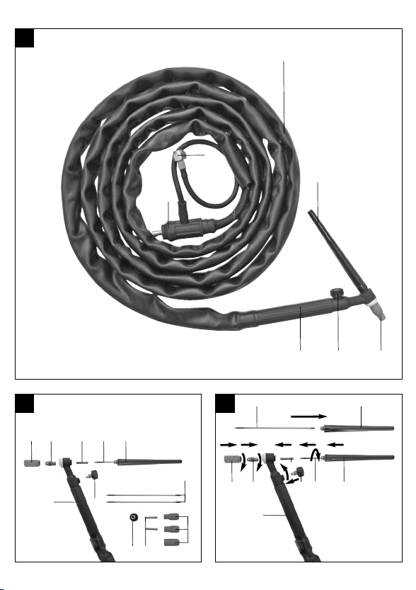
2. Gerätebeschreibung (Abb. 1/2)
1. Schlauchpaket
2. Schutzkappe lang
3. Keramikdüse
4. Drehventil für Gasdurchfluss
5. Handgriff
6. Schnellanschluss-Stecker
7. Gasanschluss
8. Kontaktrohr
9. Spannhülse
10. Wolframelektrode
11. Schutzkappe kurz
12. Schutzgasschlauch
13. Schlauchschellen
14. Adapter
D
3. Lieferumfang
Nehmen Sie alle Teile aus der Verpackung und
überprüfen Sie diese auf Vollständigkeit.
WIG-Schweissbrenner Set
6 x Keramikdüse (2 x Größe 4; 2 x Größe 5; 2 x
Größe 6)
3 x Spannhülse (2 x 1,6mm; 1 x 2,4mm)
2 x Wolframelektrode (1,6 x 73mm)
Adapter
Originalbetriebsanleitung
4. Bestimmungsgemäße Verwendung
Das WIG-Schweissbrenner Set dient zum WIGSchweißen (Wolfram-Inertgas-Schweißen) in
Kombination mit dem entsprechenden Schweißgerät
und Schutzgas.
Das Gerät darf nur nach seiner Bestimmung
verwendet werden. Jede weitere darüber
hinausgehende Verwendung ist nicht
bestimmungsgemäß. Für daraus hervorgerufene
Schäden oder Verletzungen aller Art haftet der
Benutzer/Bediener und nicht der Hersteller.
Bitte beachten Sie, dass unsere Geräte
bestimmungsgemäß nicht für den gewerblichen,
handwerklichen oder industriellen Einsatz konstruiert
wurden. Wir übernehmen keine Gewährleistung,
wenn das Gerät in Gewerbe-, Handwerks- oder
Industriebetrieben sowie bei gleichzusetzenden
Tätigkeiten eingesetzt wird.
5. Technische Daten
Schlauchpaket länge: 4 m
Spannhülsen-Durchmesser: 1,6 / 2,4 mm
Keramikdüsen: Größe 4/5/6
5

D
6. Vor Inbetriebnahme
6.1 Montage und Anschluss (Bild 3-7)
Achten Sie darauf, dass je nach dem welches
Material geschweißt werden soll, das
entsprechende Gas verwendet werden muss.
Stahl (Fe) = ArCO
Aluminium (Al) = Ar
(wird von diesem Gerät nicht unterstützt)
Edelstahl (V2A) = ArO
Montieren Sie den Schweißbrenner wie in Bild 3
dargestellt.
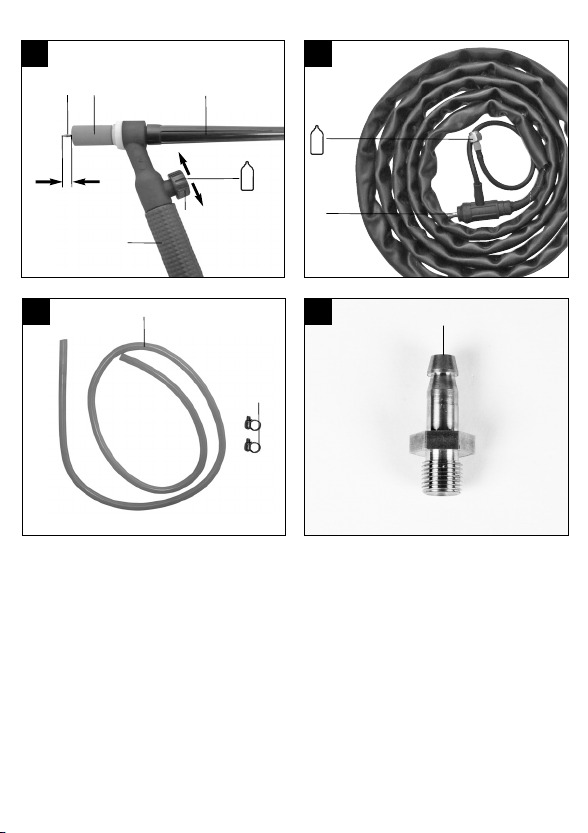
6.2 Anschluss des Schutzgasschlauches
Die beiden Schlauschellen (13) über den Schutzgasschlauch (12) führen. Schutzgasschlauch (12) auf
Anschluss für den Schutzgasschlauch am Druckminderer und Gaszuführungsanschluss am Schweißgerät stecken und an beiden Anschlussstellen mit den
Schlauchschellen (13) sichern.
Bevor Sie zu schweißen beginnen, muss die
Wolframnadel spitz angeschliffen werden. Welche
Wolframnadel bei welchem Schweißstrom verwendet
werden sollte können Sie untenstehender Tabelle
entnehmen:
Elektrode (Wolframnadel) Ø (mm) Sc hweißstrom (A)
1,6 20 – 150
2,0 100 – 160
2,4 150 – 160
Beim Einführen der Wolframnadel sollte darauf
geachtet werden, dass diese etwa 5mm aus der
Keramikdüse ragt.
Achten Sie darauf, dass eine dem Elektrodendurchmesser entsprechende Spannhülse (9) verwendet
werden muss. Der Durchmesser der Keramikdüse
(3) sollte dem Schweißstrom, der Werkstück- und
Elektrodendicke und der Gasmenge entsprechend
ausgewählt werden. Je kleiner die entsprechenden
Werte sind, desto kleiner sollte der Durchmesser der
Keramikdüse (3) sein. Bei dicken Werkstücken und
hohen Schweißströmen sollten auch dickere Wolframelektroden (10) verwendet werden. Dieses
Schlauchpaket ist für die Verwendung von Wolframelektroden (10) mit Durchmessern von 1,6 bis 2,4mm
geeignet.
6
2
2
Bei schwer zugänglichen Schweißstellen und
entsprechend kurzen Wolframelektroden (10) kann
statt der langen Schutzkappe (2) auch die kurze
Schutzkappe (11) an der Rückseite des Handgriffs
(5) verschraubt werden.
Achtung!
Achten Sie darauf, beim WIG-Schweißen das Kabel
mit der Masseklemme (9) an den Plus-Pol (5) und
die WIG-Ausrüstung an den Minus-Pol (6)
anzuschließen.
Schließen Sie den Schnellanschluss-Stecker (6) an
den Minus-Pol Ihres Schweißgeräts an und verbinden Sie den Gasanschluss (7) mit dem entsprechenden Anschluss Ihres Schweißgeräts (Bild 5).
Sollte Ihr Schweißgerät über keinen SchutzgasAnschluss verfügen, so kann der Gasanschluss (7)
auch direkt über einen Druckminderer an der
Gasflasche angeschlossen werden.
Verwenden Sie dazu den Adapter (14).
7. Bedienung
Beachten Sie die Hinweise in der Bedienungsanleitung ihres Schweißgeräts! Ermitteln Sie die
ideale Einstellung anhand eines Probestücks.
Stellen Sie die Gasdurchflussmenge (abhängig von
Schweißstrom, Elekrodendurchmesser und
Werkstückdicke) so ein, dass ein gleichmäßiger
Lichtbogen erreicht werden kann (ca. 5-15 l/min).
Hierzu nehmen Sie am Druckminderer der
Gasflasche eine grobe Voreinstellung ein, die
genaue Durchflussmenge stellen Sie am besten am
Drehventil für Gasdurchfluss (4) ein.
Wenn Sie sämtliche erforderlichen Einstellungen am
Schweißgerät vorgenommen und alle Verbindungen
hergestellt haben, gehen Sie wie folgt vor:
Zum Zünden wird nun die Keramikdüse schräg auf
das zu schweißende Material gelegt und die
Wolframnadel durch gleichmäßige, wippende
Bewegungen solange an das Material geführt bis ein
Lichtbogen entsteht. Halten Sie beim Schweißen
einen Konstanten Abstand zum Werkstück (ca. 1-1,5
mal Elektroden Ø) ein. Legen Sie Schweißbrenner
und Masseklemme nach dem Schweißen isoliert ab.

8. Reinigung, Wartung und
Ersatzteilbestellung
Ziehen Sie vor allen Reinigungsarbeiten den
Netzstecker.
8.1 Reinigung
Wir empfehlen, dass Sie das Gerät direkt nach
jeder Benutzung reinigen.
Reinigen Sie das Gerät regelmäßig mit einem
feuchten Tuch und etwas Schmierseife.
Verwenden Sie keine Reinigungs- oder
Lösungsmittel; diese könnten die Kunststoffteile
des Gerätes angreifen.
Achten Sie darauf, dass kein Wasser in das
Geräteinnere gelangen kann.
8.2 Wartung
Im Geräteinneren befinden sich keine weiteren zu
wartenden Teile.
8.3 Ersatzteilbestellung
Bei der Ersatzteilbestellung sollten folgende Angaben
gemacht werden;
Typ des Gerätes
Artikelnummer des Gerätes
Ident-Nummer des Gerätes
Ersatzteilnummer des erforderlichen Ersatzteils
Aktuelle Preise und Infos finden Sie unter
www.isc-gmbh.info
9. Entsorgung und Wiederverwertung
Das Gerät befindet sich in einer Verpackung um
Transportschäden zu verhindern. Diese Verpackung
ist Rohstoff und ist somit wieder verwendbar oder
kann dem Rohstoffkreislauf zurückgeführt werden.
Das Gerät und dessen Zubehör bestehen aus
verschiedenen Materialien, wie z.B. Metall und
Kunststoffe. Führen Sie defekte Bauteile der
Sondermüllentsorgung zu. Fragen Sie im
Fachgeschäft oder in der Gemeindeverwaltung nach!
D
7

GB
Table of contents
1. Safety regulations
2. Layout
3. Items supplied
4. Intended use
5. Technical data
6. Before starting the equipment
7. Operation
8. Cleaning, maintenance and ordering of
spare parts
9. Disposal and recycling
8

Important!
When using the equipment, a few safety precautions
must be observed to avoid injuries and damage.
Please read the complete operating instructions and
safety regulations with due care. Keep this manual in
a safe place, so that the information is available at all
times. If you give the equipment to any other person,
hand over these operating instructions and safety
regulations as well. We cannot accept any liability for
damage or accidents which arise due to a failure to
follow these instructions and the safety instructions.
1. Safety regulations
Be sure to observe the safety instructions for your
welding set.
CAUTION!
Read all safety regulations and instructions.
Any errors made in following the safety regulations
and instructions may result in an electric shock, fire
and/or serious injury.
Keep all safety regulations and instructions in a
safe place for future use.
2. Layout (Fig. 1/2)
1. Hose package
2. Protective cap, long
3. Ceramic nozzle
4. Rotary valve for gas passage
5. Handle
6. Quick-release connector plug
7. Gas connector
8. Contact pipe
9. Clamp sleeve
10. Tungsten electrode
11. Protective cap, short
12. Shielding gas hose
13. Hose clips
14. Adapter
GB
3. Items supplied
Take all parts out of the packaging and check that
they are complete.
앬 TIG welding torch set
앬 6 x ceramic nozzles (2 x size 4; 2 x size 5;
2 x size 6)
앬 3 x clamping sleeves (2 x 1.6mm; 1 x 2.4mm)
앬 2 x tungsten electrodes (1.6 x 73mm)
앬 Adapter
앬 Original operating instructions
4. Intended use
The TIG welding torch set is designed for TIG
welding (tungsten inert gas welding) in combination
with the appropriate welding set and shielding gas.
The machine is to be used only for its prescribed
purpose. Any other use is deemed to be a case of
misuse. The user / operator and not the
manufacturer will be liable for any damage or injuries
of any kind caused as a result of this.
Please note that our equipment has not been
designed for use in commercial, trade or industrial
applications. Our warranty will be voided if the
machine is used in commercial, trade or industrial
businesses or for equivalent purposes.
5. Technical data
Hose package length: 4 m
Clamping sleeve diameter: 1.6/2.4 mm
Ceramic nozzles: Size 4/5/6
9

GB
6. Before starting the equipment
6.1 Assembly and connection (Fig. 3-7)
Please note that the appropriate gas for the
material you wish to weld must be used.
Steel (Fe) = ArCO
Aluminum (Al) = Ar
(not supported by this equipment)
Stainless steel (V2A) = ArO
Assemble the welding torch as shown in Figure 3.
6.2 Connecting the shielding gas hose
Place the two hose clips (13) over the shielding gas
hose (12). Connect the shielding gas hose (12) to the
shielding gas hose connection on the pressure
reducer and gas supply connector on the welding set
and secure it to both connectors using the hose clips
(13).
Before you start welding, the tungsten needle must
be sharpened. Which tungsten needle should be
used with which welding current is shown in the table
below:
Electrode (tungsten needle)
diameter (mm) Welding current (A)
1.6 20 – 150
2.0 100 – 160
2.4 150 – 160
When you insert the tungsten needle, please note
that it should project around 5 mm out of the ceramic
nozzle.
Please note that you must use a clamping sleeve (9)
which is suitable for the electrode diameter. The
diameter of the ceramic nozzle (3) should be
selected to suit the welding current, the workpiece
thickness, the electrode thickness and the gas
delivery rate. The smaller these values are, the
smaller the diameter of the ceramic nozzle (3) should
be. Thicker tungsten electrodes (10) should be used
for thick workpieces and high welding currents. This
hose package is suitable for using tungsten
electrodes (10) with diameters from 1.6 to 2.4 mm.
For welding points with difficult access and
correspondingly short tungsten electrodes (10), the
short protective cap (11) rather than the long
protective cap (2) can be screwed on to the rear of
the handle (5).
10
2
2
Important.
Please note that for TIG welding, the cable with the
ground terminal (9) must be connected to the
positive pole (5) and the TIG equipment to the
negative pole (6).
Connect the quick-release connector plug (6) to the
negative pole on your welding set and connect the
gas connector (7) to the corresponding connector on
your welding set (Fig. 5).
If your welding set does not have a shielding gas
connector, the gas connector (7) can also be
connected straight to the gas bottle using a pressure
reducer. Use the adapter (14).
7. Operation
Refer to the instructions in the operating manual for
your welding set. Find the ideal settings using a test
workpiece.
Set the gas delivery rate (depending on the welding
current, electrode diameter and the workpiece
thickness) so that a uniform arc can be achieved
(approx. 5 – 15 l/min). Make an initial rough setting
on the pressure reducer on the gas bottle and then
set the precise delivery rate using the rotary valve for
the gas delivery rate (4).
When all the required settings have been made on
the welding set and all the connections have been
made, proceed as follows:
To ignite the torch now place the ceramic nozzle at
an angle to the material you wish to weld and guide
the tungsten needle over the material using even,
rocking movements until an arc is generated.
Maintain a constant distance to the workpiece for
welding (approx. 1 to 1.5 times the electrode
diameter). Put the welding torch and the ground
terminal on an insulated surface when you have
finished the welding.

8. Cleaning, maintenance and ordering
of spare parts
Always pull out the mains power plug before starting
any cleaning work.
8.1 Cleaning
Keep all safety devices, air vents and the motor
housing free of dirt and dust as far as possible.
Wipe the equipment with a clean cloth or blow it
with compressed air at low pressure.
We recommend that you clean the device
immediately each time you have finished using it.
Clean the equipment regularly with a moist cloth
and some soft soap. Do not use cleaning agents
or solvents; these could attack the plastic parts of
the equipment. Ensure that no water can seep
into the device.
8.2 Maintenance
There are no parts inside the equipment which
require additional maintenance.
8.3 Ordering replacement parts:
Please quote the following data when ordering
replacement parts:
Type of machine
Article number of the machine
Identification number of the machine
Replacement part number of the part required
For our latest prices and information please go to
www.isc-gmbh.info
9. Disposal and recycling
The unit is supplied in packaging to prevent its being
damaged in transit. This packaging is raw material
and can therefore be reused or can be returned to
the raw material system.
The unit and its accessories are made of various
types of material, such as metal and plastic.
Defective components must be disposed of as
special waste. Ask your dealer or your local council.
GB
11

E
Índice de contenidos
1. Instrucciones de seguridad
2. Descripción del aparato
3. Volumen de entrega
4. Uso adecuado
5. Características técnicas
6. Antes de la puesta en marcha
7. Manejo
8. Mantenimiento, limpieza y pedido de
piezas de repuesto
9. Eliminación y reciclaje
12

¡Atención!
Al usar aparatos es preciso tener en cuenta una serie
de medidas de seguridad para evitar lesiones o
daños. Por este motivo, es preciso leer atentamente
este manual de instrucciones/advertencias de
seguridad. Guardar esta información
cuidadosamente para poder consultarla en cualquier
momento. En caso de entregar el aparato a terceras
personas, será preciso entregarles, asimismo, el
manual de instrucciones/advertencias de seguridad.
No nos hacemos responsables de accidentes o
daños provocados por no tener en cuenta este
manual y las instrucciones de seguridad.
1. Instrucciones de seguridad
¡Tener en cuenta las advertencias de seguridad del
soldador!
¡AVISO!
Lea todas las instrucciones de seguridad e
indicaciones.
El incumplimiento de dichas instrucciones e
indicaciones puede provocar descargas, incendios
y/o daños graves.
Guarde todas las instrucciones de seguridad e
indicaciones para posibles consultas
posteriores.
2. Descripción del aparato (fig. 1/2)
1. Juego tubos de goma
2. Tapa protectora larga
3. Boquilla de cerámica
4. Válvula giratoria para el flujo de gas
5. Empuñadura
6. Enchufe de acoplamiento rápido
7. Toma de gas
8. Tubo de contacto
9. Manguito de sujeción
10. Electrodo de wolframio
11. Tapa protectora corta
12. Tubo de goma para gas inerte
13. Abrazaderas
14. Adaptador
E
3. Volumen de entrega
Sacar todas las piezas del embalaje y comprobar
que estén completas.
앬 Juego de sopletes para soldadura TIG
앬 6 boquillas de cerámica (2 de tamaño 4; 2 de
tamaño 5; 2 de tamaño 6)
앬 3 manguitos de sujeción (2 x 1,6 mm; 1 x 2,4 mm)
앬 2 electrodos de wolframio (1,6 x 73 mm)
앬 Adaptador
앬 Manual de instrucciones original
4. Uso adecuado
El juego de sopletes para soldadura TIG sirve para
soldar TIG (soldadura por arco en atmósfera
gaseosa con electrodo de wolframio) en
combinación con el soldador y gas inerte adecuados.
Utilizar la máquina sólo en los casos que se indican
explícitamente como de uso adecuado. Cualquier
otro uso no será adecuado. En caso de uso
inadecuado, el fabricante no se hace responsable de
daños o lesiones de cualquier tipo; el responsable es
el usuario u operario de la máquina.
Tener en consideración que nuestro aparato no está
indicado para un uso comercial, industrial o en taller.
No asumiremos ningún tipo de garantía cuando se
utilice el aparato en zonas industriales, comerciales
o talleres, así como actividades similares.
5. Características técnicas
Juego tubos de goma largos: 4 m
Diámetro de los manguitos de sujeción: 1,6 / 2,4 mm
Boquillas de cerámica: Tamaños 4/5/6
6. Antes de la puesta en marcha
6.1 Montaje y conexión (fig. 3-7)
Tener en cuenta que, dependiendo del material a
soldar, se deberá utilizar el gas correspondiente.
Acero (Fe) = ArCO
Aluminio (Al) = Ar
(no es compatible con este aparato)
2
13

E
Acero inoxidable (V2A) = ArO
Montar el soplete para soldadura como se describe
en la figura 3.
6.2 Conexión del tubo de goma para gas inerte
Poner las dos abrazaderas (13) en el tubo de goma
para gas inerte (12). Introducir el tubo de goma para
gas inerte (12) en la conexión prevista para ello en el
regulador de presión y la conexión de la alimentación
del gas del soldador y fijarlo en los dos puntos de
conexión con las abrazaderas (13).
Antes de empezar a soldar es preciso afilar la punta
de la aguja de wolframio. Consultar en la tabla a
continuación cuál es la aguja adecuada para cada
corriente de soldadura:
Electrodo (aguja de wolframio)
Ø (mm) Corriente para soldadura (A)
1,6 20 – 150
2,0 100 – 160
2,4 150 – 160
Al introducir la aguja es preciso asegurar que
sobresalga unos 5 mm de la boquilla de cerámica.
Asegurarse de que se pueda utilizar un manguito de
sujeción (9) adecuado para el diámetro de los
electrodos. El diámetro de la boquilla de cerámica
(3) se deberá elegir conforme a la corriente para
soldadura, al espesor de la pieza y de los electrodos,
así como al volumen de gas. Cuanto menores son
los valores correspondientes, menor será el diámetro
de la boquilla de cerámica (3). En el caso de piezas
de mayor espesor y corrientes de soldadura
elevadas, será preciso utilizar asimismo electrodos
de wolframio (10) mayores. Este juego de tubos de
goma es adecuado para utilizar electrodos de
wolframio (10) con diámetros de 1,6 a 2,4 mm.
En caso de que se desee soldar en puntos de difícil
acceso y, por consiguiente, con electrodos de
wolframio más cortos (10), en vez de la tapa
protectora larga (2) se podrá atornillar en la parte
trasera de la empuñadura (5) la tapa protectora corta
(11).
¡Atención!
En la soldadura TIG, asegurarse de conectar el
cable con el borne de masa (9) al polo positivo
(5) y el equipamiento TIG al polo negativo (6).
14
2
Conectar el enchufe de acoplamiento rápido (6) al
polo negativo de su soldador y conectar la toma de
gas (7) a la conexión correspondiente del soldador
(fig. 5).
Si el soldador no dispone de ninguna toma de gas
inerte, la toma de gas (7) también se podrá conectar
directamente a la bombona a través de un regulador
de presión. Utilizar para ello el adaptador (14).
7. Manejo
Tener en cuenta las instrucciones en el manual del
soldador. Determinar el ajuste ideal ensayando con
una pieza de prueba.
Ajustar el caudal de flujo de gas (dependiendo de la
corriente para soldadura, el diámetro de los
electrodos y el espesor de la pieza) de forma que se
logre un arco voltaico homogéneo (aprox. 5-15
l/min). Para ello, realizar un preajuste aproximado en
el regulador de presión de la bombona. Ajustar el
volumen de paso con ayuda de la válvula giratoria
en el flujo de gas (4).
Una vez realizados todos los ajustes y conexiones
en el soldador, proceder como sigue:
Para encender, poner la boquilla de cerámica en
posición inclinada con respecto al material para
soldar e introducir la aguja de wolframio realizando
movimientos homogéneos y basculantes hasta que
se produzca un arco voltaico. A la hora de soldar,
mantener una distancia constante con respecto a la
pieza (aprox. 1-1,5 electrodos Ø). Tras el soldado,
aislar el quemador y el borne de masa.
8. Mantenimiento, limpieza y pedido de
piezas de repuesto
Desenchufar siempre antes de realizar algún trabajo
de limpieza.
8.1 Limpieza
Reducir al máximo posible la suciedad y el polvo
en los dispositivos de seguridad, las rendijas de
ventilación y la carcasa del motor. Frotar el
aparato con un paño limpio o soplarlo con aire
comprimido manteniendo la presión baja.
Se recomienda limpiar el aparato tras cada uso.
Limpiar el aparato con regularidad con un paño
húmedo y un poco de jabón blando. No utilizar
productos de limpieza o disolventes ya que se
podrían deteriorar las piezas de plástico del

aparato. Es preciso tener en cuenta que no entre
agua en el interior del aparato.
8.2 Mantenimiento
No hay que realizar el mantenimiento a más
piezas en el interior del aparato.
8.3 Pedido de piezas de recambio:
Al solicitar recambios se indicarán los datos
siguientes:
Tipo de aparato
No. de artículo del aparato
No. de identidad del aparato
No. del recambio de la pieza necesitada.
Encontrará los precios y la información actual en
www.isc-gmbh.info
9. Eliminación y reciclaje
El aparato está protegido por un embalaje para
evitar daños producidos por el transporte. Este
embalaje es materia prima y, por eso, se puede
volver a utilizar o llevar a un punto de reciclaje.
El aparato y sus accesorios están compuestos de
diversos materiales, como, p. ej., metal y plástico.
Depositar las piezas defectuosas en un contenedor
destinado a residuos industriales. Informarse en el
organismo responsable al respecto en su municipio
o en establecimientos especializados.
E
15

P
Índice
1. Instruções de segurança
2. Descrição do aparelho
3. Material a fornecer
4. Utilização adequada
5. Dados técnicos
6. Antes da colocação em funcionamento
7. Operação
8. Limpeza, manutenção e encomenda de
peças sobressalentes
9. Eliminação e reciclagem
16

Atenção!
Ao utilizar ferramentas, devem ser respeitadas
algumas medidas de segurança para prevenir
ferimentos e danos. Por conseguinte, leia
atentamente este manual de instruções e as
instruções de segurança. Guarde-os num local
seguro, para que os possa consultar a qualquer
momento. Caso passe o aparelho a outras pessoas,
entregue também este manual de instruções e as
instruções de segurança. Não nos responsabilizamos
pelos acidentes ou danos causados pela não
observância deste manual e das instruções de
segurança.
1. Instruções de segurança
Tenha em atenção as instruções de segurança do
aparelho de soldar!
AVISO!
Leia todas as instruções de segurança e
indicações.
O incumprimento das instruções de segurança e
indicações pode provocar choques eléctricos,
incêndios e/ou ferimentos graves.
Guarde todas as instruções de segurança e
indicações para mais tarde consultar.
2. Descrição do aparelho (fig. 1/2)
1. Conjunto de tubos
2. Capa de protecção comprida
3. Bocal de cerâmica
4. Válvula rotativa para o fluxo de gás
5. Punho
6. Ficha de ligação rápida
7. Ligação de gás
8. Tubo de contacto
9. Manga de aperto
10. Eléctrodo de tungsténio
11. Capa de protecção curta
12. Tubo do gás de protecção
13. Braçadeiras
14. Adaptador
P
3. Material a fornecer
Retire todas as peças da embalagem e verifique se
estão completas.
앬 Jogo de maçarico de soldar WIG
앬 6 x bocal de cerâmica (2 x tamanho 4; 2 x
tamanho 5; 2 x tamanho 6)
앬 3 x manga de aperto (2 x 1,6 mm; 1 x 2,4 mm)
앬 2 x eléctrodo de tungsténio (1,6 x 73 mm)
앬 Adaptador
앬 Manual de instruções original
4. Utilização adequada
O jogo do maçarico de soldar WIG serve para a
soldagem WIG (gás inerte tungsténio) quando
combinado com o respectivo aparelho de soldar e
gás de protecção.
A máquina só pode ser utilizada para os fins a que se
destina. Qualquer outro tipo de utilização é
considerado inadequado. Os danos ou ferimentos de
qualquer tipo daí resultantes são da responsabilidade
do utilizador/operador e não do fabricante.
Chamamos a atenção para o facto de os nossos
aparelhos não terem sido concebidos para uso
comercial, artesanal ou industrial. Não assumimos
qualquer responsabilidade se o aparelho for utilizado
no comércio, artesanato ou indústria ou em
actividades equiparáveis.
5. Dados técnicos
Comprimento do conjunto de tubos: 4 m
Diâmetro das mangas de aperto: 1,6 / 2,4 mm
Bocais de cerâmica: Tamanho 4/5/6
6. Antes da colocação em
funcionamento
6.1 Montagem e ligação (figura 3-7)
Tenha em atenção, que o gás a utilizar deve ser o
indicado para a respectiva peça a soldar.
Aço (Fe) = Ar CO
Alumínio (Al) = Ar
(não é suportado por este aparelho)
2
17

P
Aço inoxidável (V2A) = Ar O
Monte o maçarico de soldar como indicado na figura
3.
6.2 Ligação do tubo do gás de protecção
Introduza as duas braçadeiras (13) através do tubo
do gás de protecção (12). Encaixe o tubo do gás de
protecção (12) na respectiva ligação, situada no
redutor de pressão, e na ligação de alimentação de
gás, situada no aparelho de soldar. Aperte ambos os
pontos de ligação com as braçadeiras (13).
Antes de começar a soldar, deve afiar a agulha de
tungsténio. Na tabela seguinte pode consultar quais
as agulhas de tungsténio que deve utilizar com
determinadas correntes de soldadura:
Eléctrodo (agulha de tungsténio)
Ø (mm) Corrente de soldadura (A)
1,6 20 – 150
2,0 100 – 160
2,4 150 – 160
Ao introduzir a agulha de tungsténio, deve ter em
atenção que esta tem de sobressair cerca de 5 mm
do bocal de cerâmica.
Tenha em atenção que tem de utilizar uma manga
de aperto (9) que corresponda ao diâmetro do
eléctrodo. O diâmetro do bocal de cerâmica (3) tem
de ser escolhido consoante a corrente de soldadura,
a espessura da peça a trabalhar, a espessura do
eléctrodo e a quantidade de gás. Quanto mais
pequenos forem estes valores, mais pequeno terá
de ser o diâmetro do bocal de cerâmica (3). Na
soldadura de peças grossas e com uma elevada
corrente, deve-se utilizar eléctrodos de tungsténio
(10) mais grossos. Este conjunto de tubos deve ser
utilizado com eléctrodos de tungsténio (10) com um
diâmetro de 1,6 até 2,4 mm.
Quando existem locais de soldadura de difícil acesso
e se utilizam os respectivos eléctrodos de tungsténio
curtos (10), em vez de se utilizar a capa de
protecção comprida (2), pode aparafusar-se a capa
de protecção curta (11) na parte posterior do punho
(5).
Atenção!
Tenha em atenção, que na soldadura WIG tem de
ligar o cabo com pinça de crocodilo de ligação à
massa (9) ao pólo positivo (5) e o equipamento
WIG ao pólo negativo (6).
18
2
Ligue a ficha de ligação rápida (6) no pólo negativo
do aparelho de soldar e conecte a ligação de gás (7)
na respectiva ligação do aparelho de soldar (figura
5).
Se o aparelho de soldar tiver uma ligação de gás de
protecção, pode fazer a ligação (7) directamente à
botija de gás utilizando para o efeito um redutor de
pressão. Para isso, utilize o adaptador (14).
7. Operação
Respeite as indicações do manual de instruções do
aparelho de soldar! Obtenha o ajuste ideal utilizando
uma amostra.
Regule o caudal de gás (independente da corrente
de soldadura, do diâmetro dos eléctrodos e da
grossura das peças), de forma a atingir um arco
voltaico uniforme (aprox. 5-15 l/min). Para tal, faça
um ajuste aproximado no redutor de pressão da
botija de gás, e estipule o caudal exacto na válvula
rotativa para o fluxo de gás (4).
Depois de ter feito todos os ajustes necessários no
aparelho de soldar e de ter estabelecido todas as
ligações, proceda da seguinte forma:
Para fazer a ignição, deve colocar o bocal de
cerâmica inclinado sobre o material a soldar e
esfregar, com um movimento uniforme e oscilatório,
a agulha de tungsténio na peça até que o arco
voltaico se acenda. Durante a soldadura mantenha
uma distância constante em relação à peça (aprox.
1-1,5 vezes o Ø do eléctrodo). Após a soldadura,
deponha o maçarico de soldar e a pinça crocodilo
isolados um do outro.
8. Limpeza, manutenção e encomenda
de peças sobressalentes
Retire a ficha da corrente antes de qualquer trabalho
de limpeza.
8.1 Limpeza
Mantenha os dispositivos de segurança, ranhuras
de ventilação e a carcaça do motor o mais limpo
possível. Esfregue o aparelho com um pano
limpo ou sopre com ar comprimido a baixa pres
são.
Aconselhamos a limpar o aparelho directamente
após cada utilização.
Limpe regularmente o aparelho com um pano

húmido e um pouco de sabão. Não utilize
detergentes ou solventes; estes podem corroer
as peças de plástico do aparelho. Certifique-se
de que não entra água para o interior do aparel
ho.
8.2 Manutenção
No interior do aparelho não existem quaisquer
peças que necessitem de manutenção.
8.3 Encomenda de peças sobressalentes:
Ao encomendar peças sobressalentes, devem-se
fazer as seguintes indicações:
Tipo da máquina
Número de artigo da máquina
Número de identificação da máquina
Número da peça sobressalente necessária
Pode encontrar os preços e informações actuais em
www.isc-gmbh.info
9. Eliminação e reciclagem
O aparelho encontra-se dentro de uma embalagem
para evitar danos de transporte. Esta embalagem é
matéria-prima, podendo ser reutilizada ou reciclada.
O aparelho e os respectivos acessórios são de
diferentes materiais, como por ex. o metal e o
plástico. Os componentes que não estiverem em
condições devem ter tratamento de lixo especial.
Informe-se junto das lojas da especialidade ou da
sua Câmara Municipal!
P
19

S
Innehållsförteckning
1. Säkerhetsanvisningar
2. Beskrivning av setet
3. Leveransomfattning
4. Ändamålsenlig användning
5. Tekniska data 20
6. Innan du använder setet
7. Använda setet
8. Rengöring, underhåll och
reservdelsbeställning
9. Skrotning och återvinning
20

Obs!
Innan maskinen kan användas måste särskilda
säkerhetsanvisningar beaktas för att förhindra olyckor
och skador. Läs därför noggrant igenom denna
bruksanvisning och dessa säkerhetsanvisningar.
Förvara dem på ett säkert ställe så att du alltid kan
hitta önskad information. Om maskinen ska överlåtas
till andra personer måste även denna bruksanvisning
och dessa säkerhetsanvisningar medfölja. Vi övertar
inget ansvar för olyckor eller skador som har uppstått
om denna bruksanvisning eller
säkerhetsanvisningarna åsidosätts.
1. Säkerhetsanvisningar:
Beakta säkerhetsanvisningarna som hör till ditt
svetsaggregat!
VARNING!
Läs alla säkerhetsanvisningar och instruktioner.
Försummelser vid iakttagandet av
säkerhetsanvisningarna och instruktionerna kan
förorsaka elstöt, brand och/eller svåra skador.
Förvara alla säkerhetsanvisningar och
instruktioner för framtiden.
2. Beskrivning av setet (bild 1/2)
1. Slangpaket
2. Skyddshölje, långt
3. Keramikmunstycke
4. Vridventil för gasflöde
5. Handtag
6. Stickpropp för snabbanslutning
7. Gasanslutning
8. Kontaktrör
9. Spännhylsa
10. Volframelektrod
11. Skyddshölje, kort
12. Skyddsgasslang
13. Slangklämmor
14. Adapter
S
3. Leveransomfattning
Ta ut alla delar ur förpackningen och kontrollera att
allt är komplett.
앬 TIG-svetsbrännar-set
앬 6 st keramikmunstycken (2 st strl 4; 2 st strl 5;
2 st strl 6)
앬 3 st spännhylsor (2 st 1,6 mm; 1 st 2,4 mm)
앬 2 st volframelektroder (1,6 x 73mm)
앬 Adapter
앬 Original-bruksanvisning
4. Ändamålsenlig användning
TIG-svetsbrännar-setet används till TIG-svetsning
(Tungsten Inert Gas) i kombination med ett lämpligt
svetsaggregat och skyddsgas.
Maskinen får endast användas till sitt avsedda
ändamål. Användningar som sträcker sig utöver detta
användningsområde är ej ändamålsenliga. För
materialskador eller personskador som resulterar av
sådan användning ansvarar användaren/operatören
själv. Tillverkaren påtar sig inget ansvar.
Tänk på att våra produkter endast får användas till
ändamålsenligt syfte och inte har konstruerats för
yrkesmässig, hantverksmässig eller industriell
användning. Vi ger därför ingen garanti om
produkten ska användas inom yrkesmässiga,
hantverksmässiga eller industriella verksamheter
eller vid liknande aktiviteter.
5. Tekniska data
Slangpaketets längd: 4 m
Spännhylsans diameter: 1,6 / 2,4 mm
Keramikmunstycken: strl. 4/5/6
21

S
6. Innan du använder setet
6.1 Montera och ansluta setet (bild 3-7)
Tänk på att rätt slags gas måste väljäas beroende
på materialet som ska svetsas.
Stål (Fe) = ArCO
Aluminium (Al) = Ar
(ej möjligt med detta aggregat)
Rostfritt stål (V2A) = ArO
Montera svetsbrännaren enligt beskrivningen i bild 3.
6.2 Skyddsgasslangens anslutning
Båda slangklämmorna (13) förs över
skyddsgasslangen (12). Skyddsgasslangen (12) sätts
på anslutningen för skyddsgasslangen vid
tryckreduceringsventilen och anslutningen för
gastillförseln vid svetsaggregatet och säkras vid båda
anslutningsställena med slangklämmorna (13).
Innan du börjar svetsa måste volframstiftet ha slipats
till en spets. I nedanstående tabell ser du vilket
volframstift som måste användas vid vilken
svetsström:
Elektrod (volframstift)
Ø (mm) Svetsström (A)
1,6 20 – 150
2,0 100 – 160
2,4 150 – 160
När volframstiftet förs in måste man se till att denna
skjuter ut med ca 5 mm ur keramikmunstycket.
Kom ihåg att spännhylsan (9) som används måste
passa till elektrodens diameter. Keramikmunstyckets
(3) diameter ska väljas med tanke på svetsström,
arbetsstyckets och elektrodens tjocklek samt
gasmängden. Ju mindre dessa värden är, desto
mindre måste keramikmunstyckets (3) diameter vara.
Vid tjockare arbetsstycken och högre svetsströmmar
bör även tjockare volframelektroder (10) användas.
Detta slangpaket är avsett för användning med
volframelektroder (10) vars diameter uppgår till 1,6
till 2,4 mm.
Vid svåråtkomliga svetsställen och alltför korta
volframelektroder (10), kan det korta skyddshöljet
(11) skruvas fast på baksidan av handtaget (5) i
stället för det långa skyddshöljet (2).
22
2
2
Varning!
Vid TIG-svetsning måste du se till att kabeln med
jordklämman (9) ansluts till plus-polen (5) och
TIG-utrustningen till minus-polen (6).
Anslut stickproppen för snabbanslutning (6) till
minus-polen på svetsaggregatet och koppla samman
gasanslutningen (7) till motsvarande anslutning på
svetsaggregatet (bild 5).
Om ditt svetsaggregat saknar en anslutning för
skyddsgas, så kan gasanslutningen (7) även
anslutas direkt till en gasflaska med an
tryckreducerare. Använd adaptern (14).
7. Använda setet
Beakta instruktionerna i bruksanvisningen till ditt
svetsaggregat! Svetsa på ett provstycke för att
bestämma optimal inställning.
Ställ in gasflödet (beroende på svetsström,
elektrodens diameter och arbetsstyckets tjocklek) så
att en likformig ljusbåge uppstår (ca 5-15 l/min). Gör
först en grov förinställning med gasflaskans
tryckreducerare. Ställ in det exakta gasflödet med
vridventilen (4).
Gör på följande sätt efter att du har gjort samtliga
inställningar på svetsaggregatet och utfört alla
anslutningar:
För att tända måste keramikmunstycket nu hållas
snett mot materialet som ska svetsas. För
volframstiftet fram och tillbaka med jämna vaggande
rörelser mot materialet tills en ljusbåge uppstår. Håll
ett konstant avstånd till arbetsstycket (ca 1-1,5 ggr.
elektrodens diameter) när du svetsar. Lägg ned
svetsbrännaren och jordklämman på isolerat
underlag efter att du svetsat färdigt.
8. Rengöring, Underhåll och
reservdelsbeställning
Dra alltid ut stickkontakten inför alla
rengöringsarbeten.
8.1 Rengöra maskinen
앬 Håll skyddsanordningarna,
ventilationsöppningarna och motorkåpan i så
damm- och smutsfritt skick som möjligt. Torka av
maskinen med en ren duk eller blås av den med
tryckluft med svagt tryck.
앬 Vi rekommenderar att du rengör maskinen efter

varje användningstillfälle.
앬 Rengör maskinen med jämna mellanrum med en
fuktig duk och en aning såpa. Använd inga
rengörings- eller lösningsmedel. Dessa kan skada
maskinens plastdelar. Se till att inga vätskor
tränger in i maskinens inre.
8.2 Underhåll
앬 I maskinens inre finns inga delar som kräver
underhåll.
8.3 Reservdelsbeställning
Lämna följande uppgifter vid beställning av
reservdelar:
앬 Maskintyp
앬 Maskinens artikel-nr.
앬 Maskinens ident-nr.
앬 Reservdelsnummer för erforderlig reservdel
Aktuella priser och ytterligare information finns på
www.isc-gmbh.info
9. Skrotning och återvinning
Produkten ligger i en förpackning som fungerar som
skydd mot transportskador. Denna förpackning
består av olika material som kan återvinnas. Lämna
in förpackningen till ett insamlingsställe för
återvinning.
Produkten och tillbehören består av olika material
som t ex metaller och plaster. Lämna in defekta
komponenter till ett godkänt insamlingsställe i din
kommun. Hör efter med din kommun eller med
försäljaren i din specialbutik.
S
23

FIN
Sisällysluettelo
1. Turvallisuusmääräykset
2. Laitteen kuvaus
3. Toimituksen laajuus
4. Määräysten mukainen käyttö
5. Tekniset tiedot
6. Ennen käyttöönottoa
7. Käyttö
8. Puhdistus, huolto ja varaosatilaus
9. Käytöstäpoisto ja uusiokäyttö
24

Huomio!
Laitteita käytettäessä tulee noudattaa tiettyjä
turvallisuusvarotoimia tapaturmien ja vaurioiden
välttämiseksi. Lue sen vuoksi tämä käyttöohje / nämä
turvallisuusmääräykset huolellisesti läpi. Säilytä
käyttöohje hyvin, jotta siinä olevat tiedot ovat
myöhemminkin milloin vain käytettävissäsi. Jos
luovutat laitteen muille henkilöille, ole hyvä ja anna
heille myös tämä käyttöohje / nämä
turvallisuusmääräykset laitteen mukana. Emme ota
mitään vastuuta tapaturmista tai vaurioista, jotka ovat
aiheutuneet tämän käyttöohjeen tai
turvallisuusohjeiden noudattamisen laiminlyönnistä.
1. Turvallisuusohjeet
Noudata hitsauslaitteesi turvallisuusmääräyksiä!
VAROITUS!
Lue kaikki turvallisuusmääräykset ja ohjeet.
Jos turvallisuusmääräyksiä tai muita ohjeita ei
noudateta, saattaa tästä aiheutua sähköiskuja,
tulipaloja ja/tai vaikeita vammoja.
Säilytä kaikki turvallisuusmääräykset ja ohjeet
myöhempää tarvetta varten.
2. Laitteen kuvaus (kuva 1/2)
1. Letkupaketti
2. Pitkä suojatulppa
3. Keraaminen suutin
4. Kaasunvirtauksen kääntöventtiili
5. Kahva
6. Pikaliitinpistoke
7. Kaasuliitäntä
8. Kontaktiputki
9. Kiinnitysholkki
10. Volframielektrodi
11. Lyhyt suojatulppa
12. Suojakaasuletku
13. Letkusinkilät
14. Sovitin
FIN
3. Toimituksen laajuus
Ota kaikki osat pakkauksesta, ja tarkasta, että ne
ovat täysilukuiset.
앬 TIG-hitsauspoltinsarja
앬 6 keraamista suutinta (2 x koko 4; 2 x koko 5;
2 x koko 6)
앬 3 kiinnitysholkkia (2 x 1,6 mm; 1 x 2,4 mm)
앬 2 volframielektrodia (1,6 x 73 mm)
앬 Sovitin
앬 Alkuperäiskäyttöohje
4. Määräysten mukainen käyttö
TIG-hitsauspoltinsarjaa käytetään TIG-hitsaukseen
(volframi-suojakaasu-hitsaukseen) yhdessä
vastaavan hitsauslaitteen ja suojakaasun kera.
Konetta saa käyttää ainoastaan sille määrättyyn
tarkoitukseen. Kaikkinainen tämän ylittävä käyttö ei
ole määräysten mukaista. Kaikista tästä aiheutuvista
vahingoista tai loukkaantumisista on vastuussa
laitteen omistaja/käyttäjä eikä suinkaan sen
valmistaja.
Ole hyvä ja ota huomioon, että laitteitamme ei ole
suunniteltu ja valmistettu käytettäväksi
pienteollisuus- tai teollisuustarkoituksiin. Emme siksi
ota mitään vastuuta vaurioista, jos laitetta käytetään
pienteollisuus-, käsityöläis- tai teollisuustyöpaikoilla
tai näihin verrattavissa olevissa toimissa.
5. Tekniset tiedot
Letkupaketin pituus: 4 m
Kiinnitysholkin halkaisija: 1,6/2,4 mm
Keraamiset suuttimet: Koot 4/5/6
25

FIN
6. Ennen käyttöönottoa
6.1 Asennus ja liitäntä (kuvat 3-7)
Muista, että riippuen hitsattavan materiaalin
laadusta tulee valita siihen sopiva kaasu.
Teräs (Fe) = ArCO
Alumiini (Al) = Ar
(ei tueta tällä laitteella)
Jaloteräs (V2A) = ArO
Asenna hitsauspoltin kuten kuvassa 3 näytetään.
6.2 Suojakaasuletkun liittäminen
Vedä molemmat letkusinkilät (13) suojakaasuletkun
(12) päälle. Työnnä suojakaasuletkun (12) päät
paineentasaajan suojakaasuletkun liitäntään ja
hitsauslaitteen kaasunsyöttöliitäntään ja varmista
molemmat liitännät letkusinkilöillä (13).
Ennen kuin aloitat hitsaamisen, tulee volframipuikon
kärki hioa teräväksi. Allaolevasta taulukosta voit
lukea, mitä volframipuikkoa tulee käyttää kullakin
hitsausvirralla:
Elektrodi (volframipuikko)
Ø (mm) Hitsausvirta (A)
1,6 20 – 150
2,0 100 – 160
2,4 150 – 160
Volframipuikon sisäänviennissä tulee huolehtia siitä,
että se ulottuu noin 5 mm keraamisesta suuttimesta
ulos.
Huolehdi siitä, että elektrodin halkaisijaa vastaavaa
kiinnitysholkkia (9) käytetään. Keraamisen suuttimen
(3) halkaisija tulee valita hitsausvirran,
työstökappaleen ja elektrodin paksuuden sekä
kaasumäärän mukaisesti. Mitä pienempiä vastaavat
arvot ovat, sen pienempi tulee keraamisen suuttimen
(3) halkaisijan olla. Paksuissa työstökappaleissa ja
suurissa hitsausvirroissa tulee käyttää myös
paksumpia volframielektrodeja (10). Tämä
letkupaketti sopii käytettäväksi volframielektrodien
(10) kanssa, joiden halkaisija on 1,6 - 2,4 mm.
Vaikeasti tavoitettavien hitsauskohtien ja vastaavan
lyhyiden volframielektrodien (10) kohdalla voidaan
pitkän suojatulpan (2) sijaan ruuvata kahvan (5)
takasivulle myös lyhyt suojatulppa (11).
26
2
2
Huomio!
Huolehdi siitä, että TIG-hitsauksessa
massapinteella (9) varustettu johto liitetään plus-
napaan (5) ja TIG-varusteet miinus-napaan (6).
Liitä pikaliitinpistoke (6) hitsauslaitteesi miinusnapaan ja yhdistä kaasuliitäntä (7) hitsauslaitteesi
vastaavaan liitäntään (kuva 5).
Jos hitsauslaitteessasi ei ole suojakaasuliitäntää, niin
kaasuliitännän (7) voi liittää paineentasaajan kautta
myös suoraan kaasupulloon. Käytä tätä varten
sovitinta (14).
7. Käyttö
Noudata hitsauslaitteesi käyttöohjeessa annettuja
ohjeita! Selvitä ihanteelliset asetukset koekappaleen
avulla.
Säädä kaasun virtausmäärä (riippuvainen
hitsausvirrasta, elektrodin halkaisijasta ja
työstökappaleen paksuudesta) niin, että
aikaansaadaan tasainen valokaari (n. 5-15 l/min).
Tätä varten suorita karkea esisäätö kaasupullon
paineentasaajasta, tarkan läpivirtausmäärän säädät
parhaiten kaasun läpivirtauksen kiertoventtiilistä (4).
Kun olet suorittanut kaikki tarvittavat säädöt
hitsauslaitteessa ja tehnyt kaikki liitännät, menettele
seuraavasti:
Sytyttämistä varten lasketaan keraaminen suutin
viistoon hitsattavan materiaalin pinnalle ja
volframipuikkoa liikutetaan tasaisin, keinuvin liikkein
materiaaliin niin kauan. kunnes syntyy valokaari.
Pidä hitsatessasi tasainen välimatka
työstökappaleeseen (n. 1-1,5 kertaa elektrodin
halkaisija). Laske hitsauspoltin ja massapinne
hitsauksen jälkeen eristetysti pois.
8. Puhdistus, huolto ja varaosatilaus
Irroita verkkopistoke pistorasiasta ennen kaikkia
puhdistusstoimia.
8.1 Puhdistus
앬 Pidä suojalaitteet, ilmaraot ja moottorin kotelo niin
puhtaina pölystä ja liasta kuin suinkin mahdollista.
Pyyhi laite puhtaalla rievulla tai puhalla se
puhtaaksi vähäpaineisella paineilmalla.
앬 Suosittelemme laitteen puhdistamista heti joka
käytön jälkeen.
앬 Puhdista laite säännöllisin väliajoin käyttäen

kosteaa riepua ja vähän saippuaa. Älä käytä
sellaisia puhdistusaineita tai liuotteita, jotka
saattavat syövyttää laitteen muoviosia. Huolehdi
siitä, ettei laitteen sisäpuolelle pääse vettä.
8.2 Huolto
앬 Laitteen sisäpuolella ei ole mitään huoltoa
tarvitsevia osia.
8.3 Varaosatilaus:
Varaosia tilatessasi anna seuraavat tiedot:
앬 Laitteen tyyppi
앬 Laitteen tuotenumero
앬 Laitteen tunnusnumero
앬 Tarvittavan varaosan varaosanumero.
Ajankohtaiset hinnat ja muut tiedot löydät osoitteesta
www.isc-gmbh.info
9. Käytöstäpoisto ja uusiokäyttö
Laite on pakattu kuljetuspakkaukseen, jotta vältetään
kuljetusvauriot. Tämä pakkaus on raaka-ainetta ja
sitä voi siksi käyttää uudelleen tai sen voi toimittaa
kierrätyksen kautta takaisin raaka-ainekiertoon.
Laite on ja sen varusteet on valmistettu eri
materiaaleista, kuten esim. metallista ja muoveista.
Toimita vialliset rakenneosat
oneglmajätehävitykseen. Tiedustele asiaa alan
ammattiliikkeestä tai kunnanhallitukselta!
FIN
27

HR/
BIH
Sadržaj
1. Sigurnosne napomene
2. Opis uređaja
3. Sadržaj isporuke
4. Namjenska uporaba
5. Tehnički podaci
6. Prije puštanja u pogon
7. Rukovanje
8. Čišćenje, održavanje i naručivanje rezervnih
dijelova
9. Zbrinjavanje i recikliranje
28

Pažnja!
Kod korištenja uređaja morate se pridržavati
sigurnosnih propisa kako biste spriječili ozljeđivanja i
štete. Zbog toga pažljivo pročitajte ove upute za
uporabu / sigurnosne napomene. Dobro ih sačuvajte
tako da Vam informacije u svako doba budu na
raspolaganju. Ako biste ovaj uređaj trebali predati
drugim osobama, proslijedite im i ove upute za
uporabu / sigurnosne napomene. Ne preuzimamo
odgovornost za štete koje bi nastale zbog
nepridržavanja ovih uputa za uporabu i sigurnosnih
napomena.
1. Sigurnosne upute:
Obratite pozornost na sigurnosne napomene u vezi
uređaja za zavarivanje!
UPOZORENJE!
Pročitajte sve sigurnosne napomene i upute.
Propusti kod pridržavanja sigurnosnih napomena i
uputa mogu uzrokovati el. udar, požar i/ili teška
ozljeđivanja.
Sačuvajte sve sigurnosne napomene i upute za
buduće korištenje.
2. Opis uređaja (sl. 1/2)
1. Paket crijeva
2. Zaštitna kapa, duga
3. Keramička sapnica
4. Okretni ventil za protok plina
5. Ručka
6. Utikač za brzo priključivanje
7. Priključak plina
8. Kontaktna cijev
9. Stezna čahura
10. Volfram elektroda
11. Zaštitna kapa, kratka
12. Crijevo za zaštitni plin
13. Obujmice crijeva
14. Adapter
HR/
BIH
3. Sadržaj isporuke
Izvadite sve dijelove iz pakiranja i provjerite
cjelovitost sadržaja.
앬 Komplet plamenika za WIG zavarivanje
앬 6 x keramička sapnica (2 x veličina 4;
2 x veličina 5; 2 x veličina 6)
앬 3 x stezna čahura (2 x 1,6 mm; 1 x 2,4 mm)
앬 2 x volfram elektroda (1,6 x 73 mm)
앬 Adapter
앬 Originalne upute za rukovanje
4. Namjenska uporaba
Ovaj komplet služi za tzv. WIG zavarivanje (volfram
zavarivanje inertnim plinom) u kombinaciji s
odgovarajućim uređajem za zavarivanje i zaštitnim
plinom.
Stroj se smije koristiti samo u skladu s namjenom.
Svaka drukčija uporaba izvan ovih okvira nije
namjenska. Za štete ili ozljeđivanja bilo koje vrste
koje bi iz toga proizašle ne odgovara proizvođač
nego korisnik.
Molimo da obratite pažnju na to da naši uređaji nisu
konstruirani za korištenje u komercijalne svrhe kao ni
u obrtu i industriji. Ne preuzimamo jamstvo ako se
uređaj koristi u obrtničkim ili industrijskim pogonima
i sličnim djelatnostima.
5. Tehnički podaci
Dužina crijeva u paketu: 4 m
Promjer steznih čahura: 1,6/2,4 mm
Keramičke sapnice: veličina 4/5/6
6. Prije puštanja u pogon
6.1 Montaža i priključak (slika 3 - 7)
Pripazite na to da koristite odgovarajući plin
prema materijalu koji ćete zavarivati.
Čelik (Fe) = ArCO
Aluminij (Al) = Ar
(ovim uređajem ne može se zavarivati)
Oplemenjeni čelik (V2A) = ArO
2
2
29

HR/
BIH
Uređaj za zavarivanje montirajte kao što je prikazano
na slici 3.
6.2 Priključak crijeva za zaštitni plin
Stavite obje obujmice (13) na crijevo za zaštitni plin
(12). Nataknite crijevo za zaštitni plin (12) na njegov
priključak na redukcijskom ventilu i priključak za
dovod plina na uređaju za zavarivanje i osigurajte ga
na oba priključna mjesta obujmicama (13).
Prije nego počnete sa zavarivanjem, mora se
izbrusiti volframova igla. Koja igla i struja zavarivanja
će se koristiti, možete vidjeti u sljedećoj tablici:
Elektroda (volfram igla)
Ø (mm) Struja zavarivanja [A]
1,6 20 – 150
2,0 100 – 160
2,4 150 – 160
Kod uvođenja volframove igle trebate pripaziti na to
da ona strši iz keramičke mlaznice oko 5 mm.
Pri tome obratite pozornost na to da se mora
koristiti stezna čahura (9) koja odgovara promjeru
elektroda. Promjer keramičke sapnice (3) trebalo bi
odabrati prema struji zavarivanja, debljini radnog
komada i elektrode i količini plina. Što su manje
odgovarajuće vrijednosti, manji treba biti promjer
keramičke sapnice (3). Kod debelih radnih komada i
jakih struja zavarivanja, trebalo bi također koristiti
deblje volfram elektrode (10). Ovaj paket crijeva
prikladan je za korištenje volfram elektroda (10)
promjera od 1,6 do 2,4 mm.
Kod teško pristupačnih mjesta zavarivanja i
odgovarajuće kratkih volfram elektroda (10) umjesto
duge zaštitne kape (2) može se na poleđini ručke (5)
uvrnuti i kratka zaštitna kapa (11).
Pozor!
Pripazite na to da prilikom WIG zavarivanja kabel
stezaljke za masu (9) priključite na plus pol (5) a
WIG opremu na minus pol (6).
Priključite utikač za brzo priključivanje (6) na minus
pol uređaja za zavarivanje i spojite priključak za plin
(7) s odgovarajućim priključkom uređaja za
zavarivanje (slika 5).
Ako Vaš uređaj nema priključak za zaštitni plin,
priključak plina (7) može se također spojiti direktno
preko redukcijskog ventila na plinsku bocu. Za to
koristite adapter (14).
7. Rukovanje
Pridržavajte se napomena u ovim uputama za
uporabu uređaja za zavarivanje! Pomoću probnog
komada odredite idealnu podešenost.
Podesite protočnu količinu plina (ovisno o struji
zavarivanja, promjeru elektroda i debljini radnog
komada) tako da se postigne ujednačen el. luk (oko
5 - 15 l/min). U tu svrhu prvo provedite grubo
predpodešavanje na redukcijskom ventilu plinske
boce, točnu protočnu količinu najbolje ćete podesiti
na okretnom ventilu za protok plina (4).
Kad se na uređaju za zavarivanje provedu sva
potrebna podešavanja i uspostave svi spojevi,
postupite na sljedeći način:
Za paljenje keramičku mlaznicu položite koso na
materijal koji zavarujete i vodite volframovu iglu
ravnomjernim pokretima amo-tamo tako dugo po
materijalu dok se ne upali svjetlosni luk. Kod
zavarivanja održavajte konstantni razmak do radnog
komada (oko 1-1,5 puta Ø elektrode). Nakon
zavarivanja odložite gorionik i stezaljku za masu na
izolirano mjesto.
8. Čišćenje, održavanje i narudžba
rezervnih dijelova
Prije svih radova čišćenja izvucite mrežni utikač.
8.1 Čišćenje
Zaštitne naprave, otvore za zrak i kućište motora
držite što čišćima od prašine i prljavštine. Istrl
jajte uredjaj čistom krpom ili ga ispušite
komprimiranim zrakom pod niskim tlakom.
Preporučujemo da uredjaj očistite nakon svake
uporabe.
Redovito čistite uredjaj vlažnom krpom i s malo
sapunice. Ne koristite sredstva za čišćenje ni
otapala; ona mogu oštetiti plastične dijelove
uredjaja. Pripazite na to da u unutrašnjost
uredjaja ne dospije voda.
8.2 Održavanje
U unutrašnjosti uredjaja nalaze se dijelovi koje
treba održavati.
30

8.3 Narudžba rezervnih dijelova:
Prilikom naručivanja rezervnih dijelova su potrebni
slijedeći podaci:
Tip uredjaja
Broj artikla uredjaja
Ident. broj uredjaja
Broj potrebnog rezervnog dijela
Aktualne cijene i informacije potražite na web-adresi
www.isc-gmbh.info
9. Zbrinjavanje i recikliranje
Uredjaj se nalazi u pakovanju koje ga štiti od
oštećenja prilikom transporta. Ovo pakovanje je
sirovina i zato se može ponovno upotrijebiti ili poslati
na reciklažu.
Uredjaj i njegov pribor izradjeni su od različitih
materijala kao npr. metala i plastike. Neispravne
sastavne dijelove otpremite na mjesta za
zbrinjavanje posebnog otpada. Informacije potražite
u specijaliziranoj trgovini ili nadležnoj općinskoj
upravi.
HR/
BIH
31

RS
Sadržaj
1. Bezbednosne napomene
2. Opis uređaja
3. Sadržaj isporuke
4. Namensko korišćenje
5. Tehnički podaci
6. Pre puštanja u pogon
7. Rukovanje
8. Čišćenje, održavanje i porudžbina rezervnih
delova
9. Zbrinjavanje i reciklovanje
32

Pažnja!
Kod korišćenja uređaja morate se pridržavati propisa
o bezbednosti kako biste sprečili povrede i štete.
Stoga pažljivo pročitajte ova uputstva za
upotrebu/bezbednosne napomene. Dobro ih
sačuvajte tako da Vam informacije u svako doba
budu na raspolaganju. Ako biste ovaj uređaj trebali
da predate drugim licima, prosledite im i ova
uputstva za upotrebu / bezbednosne napomene. Ne
preuzimamo garanciju za štete koje bi nastale zbog
nepridržavanja ovih uputstava za upotrebu i
bezbednosnih napomena.
1. Sigurnosna uputstva:
Obratite pažnju na bezbednosne napomene u vezi
uređaja za zavarivanje!
UPOZORENJE!
Pročitajte sve bezbednosne napomene i
uputstva.
Propusti kod pridržavanja bezbednosnih napomena i
uputstava mogu da prouzroče el.udar, požar i/ili teške
povrede.
Sačuvajte sve bezbednosne napomene i
uputstva za buduće korišćenje.
2. Opis uređaja (sl. 1/2)
1. Paket creva
2. Zaštitna kapa, duga
3. Keramička sapnica
4. Obrtni ventil za protok gasa
5. Drška
6. Utikač za brzo priključivanje
7. Priključak gasa
8. Kontaktna cev
9. Stezna čaura
10. Volfram elektroda
11. Zaštitna kapa, kratka
12. Crevo zaštitnog gasa
13. Obujmica creva
14. Adapter
RS
3. Sadržaj isporuke
Izvadite sve delove iz pakovanja i proverite
potpunost sadržaja.
앬 Komplet gorionika za WIG zavarivanje
앬 6 x keramička sapnica (2 x veličina 4; 2 x
veličina 5; 2 x veličina 6)
앬 3 x stezna čaura (2 x 1,6 mm; 1 x 2,4 mm)
앬 2 x volfram elektroda (1,6 x 73 mm)
앬 Adapter
앬 Originalna uputstva za rukovanje
4. Namensko korišćenje
Ovaj komplet služi za tzv. WIG zavarivanje (volfram
zavarivanje inertnim gasom) u kombinaciji s
odgovarajućim uređajem za zavarivanje i zaštitnim
gasom.
Mašina sme da se koristi samo prema svojoj nameni.
Svako drugačije korišćenje nije u skladu s namenom.
Za štete ili povrede bilo koje vrste koje iz toga
proizlaze odgovoran je korisnik, a ne proizvođač.
Molimo da obratite pažnju na to da naši uređaji nisu
konstruisani za korišćenje u komercijalne svrhe kao
ni u zanatu i industriji. Ne preuzimamo garanciju ako
se uređaj koristi u zanatskim ili industrijskim
pogonima i sličnim delatnostima.
5. Tehnički podaci
Dužina creva u paketu: 4 m
Prečnik steznih čahura: 1,6/2,4 mm
Keramičke sapnice: veličina 4/5/6
6. Pre puštanja u pogon
6.1 Montaža i priključak (slika 3 - 7)
Pripazite na to da koristite odgovarajući gas
prema materijalu koji ćete zavarivati.
Čelik (Fe) = ArCO
Aluminijum (Al) = Ar
(ovim uređajem ne može se zavarivati)
Plemeniti čelik (V2A) = ArO
2
2
33

RS
Uređaj za zavarivanje montirajte kao što je prikazano
na slici 3.
6.2 Priključak creva zaštitnog gasa
Stavite obe obujmice (13) na crevo za zaštitni gas
(12). Nataknite crevo zaštitnog gasa (12) na njegov
priključak na redukcionom ventilu i priključak za
dovod gasa na uređaju za zavarivanje i osigurajte ga
na oba priključna mesta obujmicama (13).
Pre nego što započnete sa zavarivanjem, mora se
izbrusiti volframova igla. Koja igla i struja zavarivanja
će se koristiti, možete videti u sledećoj tabeli:
Elektroda (volfram igla)
Ø (mm) Struja zavarivanja [A]
1,6 20 – 150
2,0 100 – 160
2,4 150 – 160
Kod uvođenja volframove igle trebate pripaziti na to
da ona strši iz keramičke mlaznice oko 5 mm.
Pri tom obratite pažnju na to da se mora koristiti
stezna čaura (9) koja odgovara prečniku elektroda.
Prečnik keramičke sapnice (3) trebalo bi izabrati
prema struji zavarivanja, debljini radnog komada i
elektrode i količini gasa. Što manje su odgovarajuće
vrednosti, to manji treba da bude prečnik keramičke
sapnice (3). Kod debelih radnih komada i jakih struja
zavarivanja, trebalo bi takođe koristiti deblje volfram
elektrode (10). Ovaj paket creva podesan je za
korišćenje volfram elektroda (10) prečnika od 1,6 do
2,4 mm.
Kod teško pristupačnih mesta zavarivanja i
odgovarajuće kratkih volfram elektroda (10) umesto
duge zaštitne kape (2) može da se na zadnjoj strani
drške (5) uvrne i kratka zaštitna kapa (11).
Pažnja!
Pripazite na to da prilikom WIG zavarivanja kabel
stezaljke za masu (9) priključite na plus pol (5) a
WIG opremu na minus pol (6).
Priključite utikač za brzo priključivanje (6) na minus
pol uređaja za zavarivanje i spojite priključak za gas
(7) s odgovarajućim priključkom uređaja za
zavarivanje (slika 5).
Ako Vaš uređaj nema priključak za zaštitni gas,
priključak gasa (7) može se takođe spojiti direktno
preko redukcionog ventila na gasnu bocu. Za to
upotrebite adapter (14).
7. Rukovanje
Pridržavajte se napomena u ovim uputstvima za
upotrebu uređaja za zavarivanje! Pomoću probnog
komada odredite idealnu podešenost.
Podesite protočnu količinu gasa (zavisno od struje
zavarivanja, prečnika elektroda i debljine radnog
komada) tako da se postigne ujednačen el. luk (oko
5-15 l/min). U tu svrhu prvo provedite grubo
predpodešavanje na redukcionom ventilu gasne
boce, tačnu protočnu količinu najbolje ćete podesiti
na obrtnom ventilu za protok gasa (4).
Kada se na uređaju za zavarivanje provedu sva
potrebna podešavanja i uspostave svi spojevi,
postupite na sledeći način:
Za paljenje keramičku mlaznicu položite koso na
materijal koji zavarujete i vodite volframovu iglu
ravnomernim pokretima amo-tamo tako dugo po
materijalu dok se ne upali svetlosni luk. Kod
zavarivanja održavajte konstantni razmak do radnog
komada (oko 1-1,5 puta Ø elektrode). Nakon
zavarivanja odložite gorionik i stezaljku za masu na
izolovano mesto.
8. Čišćenje, održavanje i narudžba
rezervnih dijelova
Prije svih radova čišćenja izvucite mrežni utikač.
8.1 Čišćenje
Zaštitne naprave, otvore za zrak i kućište motora
držite što čišćima od prašine i prljavštine.
Istrljajte uredjaj čistom krpom ili ga ispušite
komprimiranim zrakom pod niskim tlakom.
Preporučujemo da uredjaj očistite nakon svake
uporabe.
Redovito čistite uredjaj vlažnom krpom i s malo
masnog sapuna. Ne koristite sredstva za
čišćenje ni otapala; ona mogu oštetiti plastične
dijelove uredjaja. Pripazite na to da u
unutrašnjost uredjaja ne dospije voda.
8.2 Održavanje
U unutrašnjosti uredjaja nema dijelova koje treba
održavati.
34

8.3 Naručivanje rezervnih dijelova
Prilikom naručivanja rezervnih dijelova treba navesti
sljedeće podatke:
tip uredjaja
broj artikla uredjaja
identifikacijski broj uredjaja
kataloški broj potrebnog rezervnog dijela
Aktuelne cene i informacije potražite na sajtu
www.isc-gmbh.info
9. Zbrinjavanje i reciklovanje
Uredjaj se nalazi u pakovanju koje ga štiti od
oštećenja tokom transporta. Ovo pakovanje je
sirovina i zato može ponovno da se upotrebi ili
pošalje na reciklovanje. Uredjaj i njegov pribor
izradjeni su od različitih materijala kao npr. metala i
plastike. Neispravne sastavne delove otpremite na
mesta za zbrinjavanje posebnog otpada. Informacije
potražite u specijalizovanoj trgovini ili nadležnoj
opštinskoj upravi.
RS
35

TR
İçindekiler
1. Güvenlik uyarıları
2. Cihaz açıklaması
3. Sevkiyatın içeriği
4. Kullanım amacına uygun kullanım
5. Teknik özellikler
6. Çalıştırmadan önce
7. Kullanma
8. Temizleme, bakım ve yedek parça siparişi
9. Bertaraf etme ve geri kazanım
36

Dikkat!
Aletlerin kullanılmasında yaralanmaları ve hasarları
önlemek için bazı iş güvenliği kurallarına riayet
edilecektir. Bu nedenle bu Kullanma Talimatını
dikkatlice okuyunuz. Bu bilgilerin her zaman elinizin
altında olması için Kullanma Talimatını iyi bir yerde
saklayın. Aletleri başka kimselere vereceğinizde bu
Kullanma Talimatını da alet ile birlikte verin.
Kullanma Talimatı ve güvenlik uyarılarına riayet
edilmemesinden kaynaklanan iş kazaları veya
hasarlardan firmamız sorumlu değildir.
TR
3. Sevkiyatın içeriği
Bütün parçaları ambalaj içinden çıkarın ve eksik olup
olmadıklarını kontrol edin.
앬 WIG kaynak seti
앬 6 x Seramik nozul (2 x Boy 4; 2 x Boy 5;
2 x Boy 6)
앬 3 x Sıkma bileziği (2 x 1,6mm; 1 x 2,4mm)
앬 2 x Wolfram elektrodu (1,6 x 73mm)
앬 Adaptör
앬 Orijinal Kullanma talimatı
1. Güvenlik uyar∂lar∂
Kaynak makinesi ile ilgili Güvenlik Uyarılarını dikkate
alınız!
UYARI!
Tüm güvenlik bilgileri ve talimatları okuyunuz.
Güvenlik bilgileri ve talimatlarda belirtilen direktiflere
aykırı hareket edilmesi sonucunda elektrik çarpması,
yangın ve/veya ağır yaralanmalar meydana gelebilir.
Gelecekte kullanmak üzere tüm güvenlik bilgileri
ve talimatları saklayın.
2. Cihaz açıklaması (Şekil 1/2)
1. Hortum paketi
2. Uzun koruma kapağı
3. Seramik nozul
4. Gaz debi ayarı döner ventili
5. Sap
6. Fiş
7. Gaz bağlantısı
8. Temas borusu
9. Sıkma bileziği
10. Wolfram elektrodu
11. Kısa koruma kapağı
12. Gaz hortumu
13. Hotum kelepçesi
14. Adaptör
4. Kullanım amacına uygun kullanım
WIG kaynak seti, ilgili kaynak makinesi ve soygaz ile
birlikte WIG kaynak metodu (Wolfram-soygaz
kaynağı) ile kaynak uygulaması için uygundur.
Makine yalnızca kullanım amacına göre
kullanılacaktır. Kullanım amacının dışındaki tüm
kullanımlar makinenin kullanılması için uygun değildir.
Bu tür kullanım amacı dışındaki kullanımlardan
kaynaklanan hasar ve yaralanmalarda, yalnızca
kullanıcı/işletici sorumlu olup üretici firma sorumlu
tutulamaz.
Lütfen cihazlarımızın ticari, zanaatkarlar veya
endüstriyel kullanım için uygun olmadığını ve bu
kullanımlar için tasarlanmadığını dikkate alın. Aletin
ticari, zanaatkarlar veya endüstriyel veya benzer
kullanımlarda kullanılmasından kaynaklanan hasarlar
garanti kapsamına dahil değildir.
5. Teknik özellikler
Hortum paketi uzunluğu: 4 m
Sıkma bileziği çapı: 1,6 / 2,4 mm
Seramik nozullar: Boy 4/5/6
6. Çalıştırmadan önce
6.1 Montaj ve bağlantı (Şekil 3-7)
Kaynaklanacak malzemeye göre uygun kaynak
gazını kullanmanıza dikkat edin.
Çelik (Fe) = ArCO
Alüminyum (Al) = Ar
(bu alet tarafından desteklenmez)
2
37

TR
Paslanmaz çelik (krom) (V2A) = ArO
Kaynak setini (torç) Şekil 3’de gösterildiği gibi monte
edin.
6.2 Gaz hortumu bağlantısı
Her iki hortum kelepçesini (13) gaz hortumunun (12)
üzerinden geçirin. Gaz hortumunu (12), basınç
düşürücüdeki gaz bağlantısı ile kaynak aletinin gaz
giriş bağlantısına takın ve her iki bağlantı yerini hortum
kelepçelerini (13) sıkarak sabitleyin.
Kaynak uygulamasına başlamadan önce Wolfram
iğnesi sivri bir şekilde sivriltilecektir. Hangi kaynak
akımı değerinde hangi Wolfram iğnesinin kullanılacağı
aşağıda gösterilen tabloda görülebilir:
Elektrot (Wolfram iğnesi)
Ø (mm) Kaynak akımı (A)
1,6 20 – 150
2,0 100 – 160
2,4 150 – 160
Wolfram iğnesini yerleştirirken iğnenin seramik
nozuldan yaklaşık 5mm dışarı çıkmasına dikkat edin.
Montaj işleminde elektrot çapına uygun bir sıkma
bileziğinin (9) kullanılması gerektiğine dikkat edin.
Seramik nozul (3) çapı kaynak akımı, iş parçası ve
elektrot kalınlığı ve gaz miktarına uygun olarak
seçilecektir. Bu değerler ne kadar küçük olursa
seçilecek seramik nozul (3) çapı da o kadar küçük
olacaktır. Kalın iş parçaları ve yüksek kaynak akımları
ile yapılan kaynak uygulamaları için kalın Wolfram
elektrotları (10) kullanılacaktır. Bu hortum paketi,
çapları 1,6 ile 2,4mm arasında olan Wolfram
elektrotlarının (10) kullanımı için uygundur.
Zor erişilebilir kaynak yerlerine yapılan kaynak
uygulamalarında ve kısa Wolfram elektrotları (10)
kullanıldığında uzun koruma kapağı (2) yerine sapın
(5) arka tarafına kısa koruma kapağı (11) bağlanabilir.
Dikkat!
WIG kaynaklama işleminde şase penseli kabloyu
(9) artı kutup soketine (5) ve WIG donanımını eksi
kutup soketine (6) bağlayın.
Fişi (6) kaynak makinesinin eksi kutup soketine
bağlayın, gaz bağlantısını (7) kaynak makinesinin ilgili
bağlantı yerine bağlayın (Şekil 5).
2
Kaynak makinenizde gazaltı kaynak uygulaması için
gerekli bağlantı bulunmadığında gaz bağlantısı (7)
direkt olarak gaz tüpündeki basınç düşürücü armatüre
bağlanabilir. Bunun için adaptörü (14) kullanın.
7. Kullanma
Kaynak makinesinin Kullanma Talimatında açıklanan
uyarılarını dikkate alınız! Doğru elektrot kalınlığı ve
ideal kaynak akımını deneme parçası üzerinde
kaynak yaparak belirleyin.
Gaz debisini (bu değer kaynak akımı ve elektrot
çapına bağlıdır) düzenli bir ark oluşacak şekilde
ayarlayın (yakl. 5-15 ltr./dak). Bu ayarı yapmak için
önce gaz tüpündeki basınç düşürücüde ön ayar
yapın, tam doğru gaz debi ayarı ise en sağlıklı olarak
gaz debi ayarı döner ventilinde (4) yapılır.
Kaynak makinesinde gerekli olan tüm ayarları
yaptıktan ve tüm bağlantıları gerçekleştirdikten sonra
aşağıdaki işlemleri yerine getiriniz:
Kaynak uygulamasına başlama ve ateşlemek için
seramik nozulunu eğik konumda kaynatılacak
malzeme üzerine koyun ve Wolfram iğnesini düzenli,
salınımlı hareketler ile ark kaynağı oluşuncaya kadar
malzeme üzerine temas ettirin. Kaynak uygulaması
esnasında torç ile iş parçası arasında sabit bir mesafe
bırakın (elektrot çapının yaklaşık 1-1,5 katı bir
mesafe). Kaynak uygulaması sona erdikten sonra torç
ve şase kablosunu birbirine temas etmeyecek şekilde
yere koyun.
8. Temizleme, Bakım ve Yedek Parça
Siparişi
Temizleme çalışmalarına başlamadan önce elektrik
kablosunun fişini prizden çekin!
8.1 Temizleme
● Koruyucu düzenekleri, hava deliklerini ve motor
gövdesini mümkün oldukça toz ve kirden arındırın
ve temiz tutun. Cihazı temiz bir bezle silin veya
düşük basınçlı hava üfleyerek temizleyin.
● Cihazı her kullanımdan sonra hemen
temizlemenizi öneririz.
● Cihazı düzenli aralıklarla nemli bir bez ve az
miktarda sıvı sabunla temizleyin.
Deterjan veya solvent kullanmayın. Zira bu tür
maddeler cihazın plastik parçalarını tahrip
edebilir. Cihazın içine su girmemesine dikkat
edin.
38

8.2 Bakım
● Cihazın içinde bakım gerektiren başka parçalar
yoktur.
8.3 Yedek parça siparişi:
Yedek parça siparişinde aşağıda açıklanan bilgiler
verilmelidir:
● Cihaz tipi
● Cihazın ürün numarası
● Cihazın kod numarası
● Gerekli yedek parçanın yedek parça numarası
Aktüel fiyatlar ve bilgiler için internet sitemiz:
www.isc-gmbh.info
9. İmha ve Yeniden Değerlendirme
Cihaz, nakliyat hasarlarını önlemek amacıyla ambalaj
içerisindedir. Söz konusu ambalaj bir hammadde
olduğundan yeniden kullanımı mümkündür veya
hammadde geri kazanımına sevk edilmelidir.
Cihaz ve aksesuarları, örneğin metal ve plastik gibi
çeşitli malzemelerden oluşmaktadır. Bozuk parçaları
özel atık olarak imha edin. Ürünü satın aldığınız
mağazanıza veya belediyenize danışın!
TR
39

Der Nachdruck oder sonstige Vervielfältigung von Dokumentation und
Begleitpapieren der Produkte, auch auszugsweise ist nur mit ausdrücklicher Zustimmung der ISC GmbH zulässig.
The reprinting or reproduction by any other means, in whole or in part,
of documentation and papers accompanying products is permitted only
with the express consent of ISC GmbH.
La reimpresión o cualquier otra reproducción de documentos e
información adjunta a productos, incluida cualquier copia, sólo se
permite con la autorización expresa de ISC GmbH.
A reprodução ou duplicação, mesmo que parcial, da documentação e
dos anexos dos produtos, carece da autorização expressa da ISC
GmbH.
Eftertryck eller annan duplicering av dokumentation och medföljande
underlag för produkter, även utdrag, är endast tillåtet med uttryckligt
tillstånd från ISC GmbH.
q
Tuotteiden dokumentaatioiden ja muiden mukaanliitettyjen asiakirjojen
vain osittainenkin kopiointi tai muunlainen monistaminen on sallittu
ainoastaan ISC GmbH:n nimenomaisella luvalla.
Bf
Naknadno tiskanje ili slična umnožavanja dokumentacije i pratećih
papira ovih proizvoda, čak i djelomično kopiranje, moguće je samo uz
izričito dopuštenje tvrtke ISC GmbH.
4
Potpuno ili delimično štampanje ili umnožavanje dokumentacije i
službenih papira koji su priloženi proizvodu dozvoljeno je samo uz
izričitu saglasnost firme ISC GmbH.
Ürünlerinin dokümantasyonu ve evraklar∂n∂n k∂smen olsa dahi
kopyalanmas∂ veya baμka μekilde ço©alt∂lmas∂, yaln∂zca ISC GmbH
firmas∂n∂n özel onay∂ al∂nmak μart∂yla serbesttir.
40

Technische Änderungen vorbehalten
Technical changes subject to change
Salvo modificaciones técnicas
Salvaguardem-se alterações técnicas
Förbehåll för tekniska förändringar
q Oikeus teknisiin muutoksiin pidätetään
Bf Zadržavamo pravo na tehnične izmjene.
4 Zadržavamo pravo na tehničke promen
Teknik de©iμiklikler olabilir
41

42

t
GUARANTEE CERTIFICATE
Dear Customer,
All of our products undergo strict quality checks to ensure that they reach you in perfect condition. In the unlikely
event that your device develops a fault, please contact our service department at the address shown on this
guarantee card. Of course, if you would prefer to call us then we are also happy to offer our assistance under
the service number printed below. Please note the following terms under which guarantee claims can be made:
1. These guarantee terms cover additional guarantee rights and do not affect your statutory warranty rights.
We do not charge you for this guarantee.
2. Our guarantee only covers problems caused by material or manufacturing defects, and it is restricted to the
rectification of these defects or replacement of the device. Please note that our devices have not been
designed for use in commercial, trade or industrial applications. Consequently, the guarantee is invalidated
if the equipment is used in commercial, trade or industrial applications or for other equivalent activities. The
following are also excluded from our guarantee: compensation for transport damage, damage caused by
failure to comply with the installation/assembly instructions or damage caused by unprofessional
installation, failure to comply with the operating instructions (e.g. connection to the wrong mains voltage or
current type), misuse or inappropriate use (such as overloading of the device or use of non-approved tools
or accessories), failure to comply with the maintenance and safety regulations, ingress of foreign bodies
into the device (e.g. sand, stones or dust), effects of force or external influences (e.g. damage caused by
the device being dropped) and normal wear resulting from proper operation of the device. This applies in
particular to rechargeable batteries for which we nevertheless issue a guarantee period of 12 months.
The guarantee is rendered null and void if any attempt is made to tamper with the device.
3. The guarantee is valid for a period of 2 years starting from the purchase date of the device. Guarantee
claims should be submitted before the end of the guarantee period within two weeks of the defect being
noticed. No guarantee claims will be accepted after the end of the guarantee period. The original guarantee
period remains applicable to the device even if repairs are carried out or parts are replaced. In such cases,
the work performed or parts fitted will not result in an extension of the guarantee period, and no new
guarantee will become active for the work performed or parts fitted. This also applies when an on-site
service is used.
4. In order to assert your guarantee claim, please send your defective device postage-free to the address
shown below. Please enclose either the original or a copy of your sales receipt or another dated proof of
purchase. Please keep your sales receipt in a safe place, as it is your proof of purchase. It would help us if
you could describe the nature of the problem in as much detail as possible. If the defect is covered by our
guarantee then your device will either be repaired immediately and returned to you, or we will send you a
new device.
Of course, we are also happy offer a chargeable repair service for any defects which are not covered by the
scope of this guarantee or for units which are no longer covered. To take advantage of this service, please send
the device to our service address.
43

m
CERTIFICADO DE GARANTÍA
Estimado cliente:
Nuestros productos están sometidos a un estricto control de calidad. No obstante, lamentaríamos que este
aparato dejara de funcionar correctamente, en tal caso, le rogamos que se dirija a nuestro servicio de atención
al cliente en la dirección indicada en la parte inferior de la presente tarjeta de garantía. Con mucho gusto le
atenderemos también telefónicamente en el número de servicio indicado a continuación. Para hacer válido el
derecho de garantía, proceda de la siguiente forma:
1. Estas condiciones de garantía regulan prestaciones de la garantía adicionales. Sus derechos legales a
prestación de garantía no se ven afectados por la presente garantía. Nuestra prestación de garantía es
gratuita para usted.
2. La prestación de garantía se extiende exclusivamente a defectos ocasionados por fallos de material o de
producción y está limitada a la reparación de los mismos o al cambio del aparato. Tenga en consideración
que nuestro aparato no está indicado para un uso comercial, en taller o industrial. Por lo tanto, no
procederá un contrato de garantía cuando se utilice el aparato en zonas industriales, comerciales o talleres,
así como actividades similares. De nuestra garantía se excluye cualquier otro tipo de prestación adicional
por daños ocasionados por el transporte, daños ocasionados por la no observancia de las instrucciones de
montaje o por una instalación no profesional, no observancia de las instrucciones de uso (como, p. ej.,
conexión a una tensión de red o corriente no indicada), aplicaciones impropias o indebidas (como, p. ej.,
sobrecarga del aparato o uso de herramientas o accesorios no homologados), no observancia de las
disposiciones de mantenimiento y seguridad, introducción de cuerpos extraños en el aparato (como, p. ej.,
arena, piedras o polvo), uso violento o influencias externa (como, p. ej., daños por caídas), así como por el
desgaste habitual por el uso. Esto se aplica especialmente en aquellas baterías para las que ofrecemos un
plazo de garantía de 12 meses.
El derecho a garantía pierde su validez cuando ya se hayan realizado intervenciones en el aparato.
3. El periodo de garantía es de 2 años y comienza en la fecha de la compra del aparato. El derecho de
garantía debe hacerse válido, antes de finalizado el plazo de garantía, dentro de un periodo de dos
semanas una vez detectado el defecto. El derecho de garantía vence una vez transcurrido el plazo de
garantía. La reparación o cambio del aparato no conllevará ni una prolongación del plazo de garantía ni un
nuevo plazo de garantía ni para el aparato ni para las piezas de repuesto montadas. Esto también se aplica
en el caso de un servicio
4. Para hacer efectivo su derecho a garantía, envíe gratuitamente el aparato defectuoso a la dirección
indicada a continuación. Adjunte el original del ticket de compra u otro tipo de comprobante de compra con
fecha. ¡A tal efecto, guarde en lugar seguro el ticket de compra como comprobante! Describa con la mayor
precisión posible el motivo de la reclamación. Si nuestra prestación de garantía incluye el defecto
aparecido en el aparato, recibirá de inmediato un aparato reparado o nuevo de vuelta.
Naturalmente, también solucionaremos los defectos del aparato que no se encuentren comprendidos o ya no
se encuentren comprendidos en la garantía, en este caso contra reembolso de los costes. Para ello, envíe el
aparato a nuestra dirección de servicio técnico.
in situ
.
44

O
CERTIFICADO DE GARANTIA
Estimado(a) cliente,
Os nossos produtos são submetidos a um rigoroso controlo de qualidade. Se, ainda assim, o aparelho não
funcionar nas devidas condições, lamentamos esse facto e pedimos-lhe que se dirija ao nosso serviço de
assistência técnica na morada indicada no presente certificado de garantia. Se preferir, também pode
contactar-nos telefonicamente através do número de assistência técnica abaixo indicado. O exercício dos
direitos de garantia está sujeito às seguintes condições:
1. As presentes condições de garantia regem as prestações de garantia complementar e não afectam os
seus direitos legais de garantia. O nosso serviço de garantia é prestado gratuitamente.
2. A garantia cobre exclusivamente os defeitos de material ou de fabrico e limita-se à reparação de tais
defeitos ou à substituição do aparelho. Chamamos a atenção para o facto de os nossos aparelhos não
terem sido concebidos para uso comercial, artesanal ou industrial. Não haverá, por isso, lugar a um
contrato de garantia no caso de o aparelho ser utilizado em empresas do comércio, do artesanato ou da
indústria ou em actividades equiparáveis. A nossa garantia exclui, além disso, quaisquer indemnizações
por danos de transporte, danos resultantes da não observância das instruções de montagem ou de uma
instalação incorrecta, da não observância das instruções de funcionamento (por exemplo, ligação a uma
tensão de rede ou a um tipo de corrente errado), de uma utilização abusiva ou indevida (como, por
exemplo, sobrecarga do aparelho ou utilização de ferramentas ou acessórios não autorizados), da não
observância das regras de manutenção e segurança, da penetração de corpos estranhos no aparelho (por
exemplo, areia, pedras ou pó), do uso da força ou de impactos externos (como, por exemplo, danos
causados pela queda do aparelho), bem como do desgaste normal resultante da utilização do aparelho.
Isto é válido especialmente para os acumuladores aos quais concedemos uma garantia de 12 meses.
O direito de garantia extingue-se no caso de já ter havido uma tentativa de reparação do aparelho.
3. O período de garantia é de 2 anos a contar da data de compra do aparelho. Os direitos de garantia devem
ser reclamados dentro do período de garantia, no prazo de duas semanas após ter sido detectado o
defeito. Está excluída a reclamação de direitos de garantia após o termo do período de garantia. A
reparação ou a substituição do aparelho não implica o prolongamento do período de garantia nem dá
origem à contagem de um novo período de garantia para o aparelho ou para eventuais peças de
substituição montadas no mesmo. O mesmo se aplica no caso de a assistência técnica ter sido prestada
no local.
4. Para activar a garantia deverá enviar o aparelho defeituoso à cobrança para a morada abaixo indicada,
juntamente com o talão de compra original ou qualquer outro documento comprovativo da data de compra.
Por isso, é importante que guarde o talão de compra como comprovativo. Descreva o mais
detalhadamente possível o motivo da reclamação. Se o defeito do aparelho estiver abrangido pelo nosso
serviço de garantia, ser-lhe-á imediatamente enviado um aparelho novo ou reparado.
Naturalmente, também teremos todo o gosto em efectuar reparações que não estão, ou deixaram de estar,
abrangidas pelo serviço de garantia. Nesse caso, terá de suportar os custos da reparação. Para este efeito,
deverá enviar o aparelho para a morada do nosso serviço de assistência técnica.
45

U
GARANTIBEVIS
Bästa kund,
Våra produkter genomgår en sträng kvalitetskontroll. Om denna produkt mot förmodan inte fungerar på rätt sätt,
beklagar vi detta och ber dig att kontakta vår serviceavdelning under adressen som anges på garantikortet. Vi
står även gärna till tjänst på telefon under servicenumret som anges nedan. Följande punkter gäller för att du
ska kunna göra anspråk på garantin:
1. I dessa garantivillkor regleras extra garantitjänster. Garantianspråk som regleras enligt lag påverkas inte av
denna garanti. Våra garantitjänster är gratis för dig.
2. Garantitjänsterna täcker endast in sådana brister som kan härledas till material- eller fabrikationsfel och är
begränsade till arbetsuppgifter som syftar till att åtgärda dessa brister eller byta ut produkten. Tänk på att
våra produkter endast får användas till ändamålsenligt syfte och inte har konstruerats för yrkesmässig,
hantverksmässig eller industriell användning. Ett garantiavtal sluts därför ej om produkten ska användas
inom yrkesmässiga, hantverksmässiga eller industriella verksamheter eller vid liknande aktiviteter. Vår
garanti omfattar dessutom inte ersättning för transport skador, skador som kan härledas till missaktade
monterings anvisningar eller ej föreskriven installation, åsidosatt bruksanvisning (t ex anslutning till felaktig
nätspänning eller strömart), missbruk eller ej ändamålsenliga användningar (t ex överbelastning av
produkten eller användning av ej godkända insatsverktyg eller tillbehör), åsidosatta underhålls- och
säkerhetsbestämmelser, främmande partiklar som har trängt in i produkten (t ex sand, sten eller damm),
yttre våld eller yttre påverkan (t ex skador om produkten har fallit ned) samt normalt och användningsbundet
slitage. Detta gäller särskilt för batterier som täcks av en 12 månaders garanti.
Anspråk på garanti upphör att gälla om ingrepp redan har gjorts i produkten.
3. Garantitiden uppgår till 2 år och gäller från datumet när produkten köptes. Medan garantitiden fortfarande
gäller ska anspråk på garanti ställas inom två veckor efter att defekten fastställdes. Det är inte möjligt att
ställa anspråk på garanti efter att garantitiden har löpt ut. Garantitiden förlängs inte när produkten repareras
eller byts ut, dessutom medför sådana arbeten inte att en ny garantitid börjar gälla för produkten eller för ev.
reservdelar som har monterats in. Detta gäller även vid hembesök.
4. För att du ska kunna ställa anspråk på garantin ska den defekta produkten skickas in i tillräckligt frankerat
skick till adressen som anges nedan. Bifoga kvittot i original eller ett annat daterat köpebevis. Förvara därför
kassakvittot på en säker plats! Beskriv orsaken till reklamationen så noggrant som möjligt. Om defekten i
produkten täcks av våra garantitjänster, får du genast en reparerad eller ny apparat av oss.
Givetvis kan vi även, mot debitering, åtgärda skador som antingen inte täcks av garantin eller som har uppstått
efter garantitidens slut. Skicka in produkten till nedanstående serviceadress.
46

q
TAKUUTODISTUS
Arvoisa asiakas,
tuotteemme läpikäyvät erittäin tiukan laadunvalvontatarkastuksen. Mikäli tämä laite ei kuitenkaan toimi
moitteettomasti, valitamme tapahtunutta suuresti ja pyydämme sinua kääntymään teknisen asiakaspalvelumme
puoleen käyttäen tässä takuukortissa annettua osoitetta. Voit halutessasi myös ottaa yhteyttä puhelimitse
allaolevaan palvelunumeroon. Takuuvaateiden esittämistä koskevat seuraavat säädökset:
1. Nämä takuumääräykset koskevat laajennettuja takuusuorituksia. Ne eivät vaikuta lakimääräisiin
takuusuoritusvaateisiisi millään tavalla. Takuumme on sinulle maksuton.
2. Takuusuoritus kattaa ainoastaan sellaiset puutteellisuudet, jotka aiheutuvat materiaali- tai
valmistusvirheistä, ja se on rajattu ainoastaan näiden puutteellisuuksien korjaamiseen tai laitteen
korvaamiseen uudella. Ole hyvä ja ota huomioon, että laitteitamme ei ole suunniteltu ja valmistettu
käytettäväksi pienteollisuus-, käsityöläis- tai teollisuustarkoituksiin. Takuusopimusta ei siksi synny, jos
laitetta käytetään pienteollisuus-, käsityöläis- tai teollisuustyöpaikoilla tai näihin verrattavissa olevissa
toimissa. Takuumme ei myöskään sisällä kuljetusvaurioiden tai sellaisten vaurioiden korvaussuorituksia,
jotka ovat aiheutuneet asennusohjeen noudattamatta jättämisestä tai asiantuntemattomasta asennuksesta,
käyttöohjeen noudattamatta jättämisestä (esim. liitäntä vääräntyyppiseen verkkovirtaan), väärinkäytöstä tai
virheellisestä käytöstä (esim. laitteen ylikuormittaminen tai hyväksymättömien työkalujen tai lisävarusteiden
käyttäminen), huolto- ja turvallisuusmääräysten noudattamatta jättämisestä, vieraiden esineiden (esim.
hiekan, kivien tai pölyjen) pääsystä laitteen sisään, väkivaltaisesta käsittelystä tai ulkopuolisista tekijöistä
(esim. putoamisesta aiheutuneet vauriot) sekä käytöstä aiheutuvasta tavallisesta kulumisesta. Tämä
koskee erityisesti niitä akkuja, joille me kuitenkin myönnämme 12 kuukauden pituisen takuun.
Takuuvaateet raukeavat, jos laitteelle on jo tehty jotain toimenpiteitä.
3. Takuuaika on 2 vuotta ja se alkaa laitteen ostopäivästä. Takuuvaateet tulee esittää ennen takuuajan
päättymistä kahden viikon kuluessa siitä, kun olet havainnut vian. Takuuvaateiden esittäminen takuuajan
päätyttyä ei ole mahdollista. Laitteen korjaus tai vaihto ei johda takuuajan pitenemiseen tai laitteen tai siihen
mahdollisesti asennettujen varaosien takuuajan alkamiseen uudelleen alusta. Tämä koskee myös paikan
päällä suoritettuja palveluja.
4. Takuuvaateesi esittämiseksi tulee viallinen laite lähettää postikulut maksettuna allaolevaan osoitteeseen.
Ole hyvä ja liitä mukaan alkuperäinen maksukuitti tai muu päiväyksellä varustettu ostotosite. Säilytä tämän
vuoksi kassakuitti huolella tositteena! Ole hyvä ja kuvaa valituksen syy meille mahdollisimman tarkoin. Jos
takuumme kattaa laitteessa olevan vian, saat korjatun tai uuden laitteen välittömästi takaisin.
Tietysti korjaamme mielellämme korvausta vastaan myös sellaiset laitteiden viat, jotka eivät kuulu tai eivät enää
kuulu takuumme piiriin. Lähetä tätä varten laite tekniseen asiakaspalveluumme allaolevalla osoitteella.
47

Bf
Poštovani kupče,
naši proizvodi podliježu strogoj kontroli kvalitete. Žao nam je ako bi ipak došlo do toga da uređaj ne funkcionira
besprijekorno i zamolili bismo Vas da se u tom slučaju obratite na adresu naše servisne službe navedenu ispod
ovog jamstva. Također smo Vam na raspolaganju na dolje navedenom telefonskom broju servisne službe. Za
traženje jamstvenog zahtjeva vrijedi sljedeće:
1. Ovi jamstveni uvjeti reguliraju dodatne jamstvene usluge. Ovo jamstvo ne zadire u Vaše zakonsko pravo
zahtjeva za ostvarenje jamstvenih usluga. Realizacija jamstvenih usluga je besplatna.
2. Jamstvena usluga obuhvaća isključivo nedostatke nastale zbog greške na materijalu ili tijekom proizvodnje i
ograničen je na uklanjanje tih nedostataka odnosno zamjenu uređaja. Molimo da obratite pažnju na to da
naši uređaji nisu konstruirani za korištenje u komercijalne svrhe niti u obrtu i industriji. Prema tome, ugovor o
jamstvu ne može se ostvariti ako se uređaj koristi u obrtničkim ili industrijskim pogonima kao i u sličnim
djelatnostima. Nadalje su iz jamstva isključene usluge zamjene proizvoda u slučaju transportnih oštećenja,
šteta zbog nepridržavanja uputa za montažu ili zbog nestručne instalacije, nepridržavanja uputa za uporabu
(kao npr. zbog priključka na pogrešni mrežni napon ili vrstu struje), zbog zloporaba ili nestručnih primjena
(kao npr. preopterećenje uređaja ili korištenje nedopuštenih alata ili pribora), u slučaju nepridržavanja uputa
za održavanje i sigurnosnih odredbi, zbog prodiranja stranih tijela u uređaj (npr. pijeska, kamenja ili
prašine), nasilne primjene ili vanjskih utjecaja (kao npr. oštećenja zbog pada) kao i zbog uobičajenog
trošenja tijekom korištenja. To naročito vrijedi za baterije za koje ipak dajemo jamstvo od 12 mjeseci.
Zahtjev za jamstvo prestaje biti valjan ako su na uređaju već izvršeni neki zahvati.
3. Jamstveni rok iznosi 2 godine a započinje s datumom kupnje uređaja. Jamstveni zahtjevi ostvaruju se prije
isteka jamstvenog roka unutar dvije godine nakon što ste uočili kvar. Ostvarenje jamstvenog zahtjeva nakon
isteka jamstvenog roka je isključeno. Popravkom ili zamjenom uređaja ne produljuje se jamstveni rok niti se
tom uslugom ostvarujenovi jamstveni rok za uređaj ili ostale ugrađene rezervne dijelove. To također vrijedi i
kod korištenja servisa na licu mjesta.
4. Da biste ostvarili svoj jamstveni zahtjev, molimo Vas da nam pošaljete neispravan uređaj bez plaćanja
poštarine na dolje navedenu adresu. Priložite originalni računa za kupnju uređaja ili neki drugi dokaz o
kupnji s datumom. Molimo Vas da zbog tog razloga dobro sačuvate račun kao dokaz! Što točnije opišite
razlog reklamacije. Ako naša jamstvena usluga obuhvaća kvar nastao na Vašem uređaju, odmah ćemo
Vam vratiti popravljeni ili novi uređaj.
Razumljivo je da ćemo za naknadu troškova ukloniti i kvarove koje jamstvena usluga ne obuhvaća. U tom
slučaju pošaljite uređaj na adresu našeg servisa.
JAMSTVENI LIST
48

4
GARANCIJSKI LIST
Poštovani kupče,
naši proizvodi podvrgavaju se strogoj kontroli kvalitete. Žao nam je ako bi se ipak desilo da uređaj ne
funkcioniše besprekorno i zamolili bismo Vas da se u tom slučaju obratite na adresu naše servisne službe
navedenu ispod ove garancije. Takođe smo Vam na raspolaganju na dole navedenom telefonskom broju
servisne službe. Kod zahteva za realizovanje garancije vredi sledeće:
1. Ovi garantni uslovi regulišu dodatne garancije. Ova garancija ne dotiče Vaše zakonsko pravo zahteva za
ostvarenje garancije. Realizacija garancije je besplatna.
2. Garancija obuhvata isključivo nedostatke koji nastanu zbog pogreške na materijalu ili tokom proizvodnje i
ograničen je na odstranjivanje tih nedostataka odnosno zamenu uređaja. Molimo da obratite pažnju na to
da naši uređaji nisu konstruisani za korišćenje u komercijalne svrhe, niti u obrtu i industriji. Prema tome
ugovor o garanciji ne može da se ostvari, ako se uređaj koristi u obrtničkim ili fabričkim pogonima, kao i u
sličnim delatnostima. Nadalje su iz garancije isključene usluge zamene proizvoda u slučaju transportnih
oštećenja, šteta zbog nepridržavanja uputstava za montažu ili zbog nestručne instalacije, nepridržavanja
uputstava za upotrebu (kao npr. zbog priključka na pogrešan mrežni napon ili vrstu struje), zbog
zloupotreba ili nestručnih primena (kao npr. preopterećenje uređaja ili korišćenje nedozvoljenih alata ili
pribora), u slučaju nepridržavanja uputstava za održavanje i bezbednosnih odredaba, zbog prodiranja
stranih tela u uređaj (npr. peska, kamenja ili prašine), nasilne primene ili spoljnih uticaja (kao npr. oštećenja
zbog pada) kao i zbog uobičajenog habanja tokom korišćenja. To naročito vredi za baterije za koje ipak
dajemo garanciju od 12 meseci.
Zahtev za garanciju prestaje važiti ako su na uređaju već izvršeni neki zahvati.
3. Garantni rok iznosi 2 godine a počinje sa datumom kupnje uređaja. Garantni zahtjevi ostvaruju se pre isteka
garantnog roka unutar dve godine nakon što ste uočili kvar. Realizacija garantnog zahteva nakon isteka
garantnog roka je isključeno. Popravkom ili zamenom uređaja ne produžava se garantni rok niti se tom
uslugom realizuje novi jamstveni rok za uređaj ili ostale ugrađene rezervne delove. To također važi i kod
korišćenja servisa na licu mesta.
4. Da biste ostvarili svoj garantni zahtev, molimo Vas da nam pošaljete neispravan uređaj bez plaćanja
poštarine na dole navedenu adresu. Priložite original računa za kupnju uređaja ili neki drugi dokaz o kupnji s
datumom. Molimo Vas da iz tog razloga dobro sačuvate račun kao dokaz! Što tačnije opišite razlog
reklamacije. Ako naša garancija obuhvata kvar koji je nastao na Vašem uređaju, odmah ćemo Vam vratiti
popravljen ili novi uređaj.
Podrazumeva se da ćemo za nadoknadu troškova ukloniti i one kvarove koje garancija ne obuhvata. U tom
slučaju pošaljite uređaj na adresu našeg servisa.
49

Z
GARANTİ BELGESİ
Sayın Müşterimiz,
Ürünlerimiz üretim esnasında sıkı bir kalite kontrolden geçirilir. Buna rağmen alet veya cihazınız tam doğru
şekilde çalışmadığında ve bozulduğunda bu durumdan çok üzgün olduğumuzu belirtir ve bozuk olan aleti/cihazı
Garanti Belgesinin alt bölümünde açıklanan Servis Hizmetlerine göndermenizi rica ederiz. Bize ayrıca aşağıda
açıklanan Servis telefon numarasından da her zaman ulaşabilirsiniz. Size her konuda memnuniyetle bilgi veririz.
Garanti haklarından faydalanmak için aşağıdaki kurallar geçerlidir:
1. Bu Garanti koşulları ek Garanti Hizmetlerini düzenler. Kanuni Garanti Haklarınız bu Garanti
düzenlemesinden etkilenmez ve saklı kalır. Garanti kapsamında sunduğumuz hizmetler ücretsizdir.
2. Garanti kapsamına sadece malzeme ve üretim hatasından kaynaklanan eksiklik ve ayıplar dahildir. Bu
durumlarda garanti hizmetleri sadece arızanın onarımı veya aletin/cihazın değiştirilmesi ile sınırlıdır.
Aletlerimizin ve cihazlarımızın ticari ve endüstriyel kullanım amacı için tasarlanmadığını lütfen dikkate alınız.
Bu nedenle aletin/cihazın ticari ve endüstriyel işletmelerde kullanılması veya benzer çalışmalarda
çalıştırılması durumunda Garanti Sözleşmesi geçerli değildir. Ayrıca transport hasarları, montaj talimatına
veya yönetmeliklere aykırı yapılan montajlardan ve tesisatlardan kaynaklanan hasarlar, kullanma talimatına
riayet etmeme nedeniyle oluşan hasarlar (örneğin yanlış bir şebeke gerilimine veya akım türüne bağlama
gibi), kullanım amacına veya talimatlara aykırı kullanımdan kaynaklanan hasarlar (örneğin alete/cihaza aşırı
yüklenme veya kullanımına izin verilmeyen alet veya aksesuar), bakım ve güvenlik talimatlarına riayet
edilmemesinden kaynaklanan hasarlar, aletin/cihazın içine yabancı maddenin girmesi (örneğin kum, taş
veya toz), zor kullanma veya harici zorlamalardan kaynaklanan hasarlar (örneğin aşağı düşme nedeniyle
oluşan hasar) ve kullanıma bağlı olağan aşınma gibi durumlar garanti kapsamına dahil değildir. Bu durum
özellikle halen 12 ay garantisi olan aküler için geçerlidir
Alet/cihaz üzerinde herhangi bir çalışma yapıldığında veya müdahalede bulunulduğunda garanti hakkı sona
erer.
3. Garanti süresi 2 yıldır ve garanti süresi aletin/cihazın satın alındığı tarihde başlar. Arızayı tespit ettiğinizde
garanti hakkından faydalanma talebi, garanti süresi dolmadan iki hafta önce bildirilmelidir. Garanti süresi
dolduktan sonra garanti hakkından faydalanma talebinde bulunulamaz. Aletin/cihazın onarılması veya
değiştirilmesi garanti süresinin uzamasına yol açmaz ayrıca onarılan alet veya takılan parçalar için yeni bir
garanti süresi oluşmaz. Bu aynı zamanda yerinde verilen Servis Hizmetleri için de geçerlidir.
4. Garanti hakkından faydalanmak için arızalı aleti, gönderi ücreti göndericiye ait olmak üzere aşağıda belirtilen
adrese postalayın. Satın aldığınız tarihi belirten orijinal fişi veya başka bir belgeyi de alet ile birlikte gönderin.
Bu nedenle kasa fişini belgelemek için daima iyice saklayın! Arıza ve şikayet sebebini mümkün olduğunca
doğru şekilde açıklayın. Aletin arızası garanti kapsamına dahil olduğunda size en kısa zamanda onarılmış
veya yeni bir alet/cihaz gönderilecektir.
Ayrıca garanti kapsamına dahil olmayan veya garant isüresi dolan arızaları ücreti karşılığında memuniyetle
onarırız. Bunun için aleti/cihazı lütfen Servis adresimize gönderin.
50

k
GARANTIEURKUNDE
Sehr geehrte Kundin, sehr geehrter Kunde,
unsere Produkte unterliegen einer strengen Qualitätskontrolle. Sollte dieses Gerät dennoch einmal nicht einwandfrei funktionieren, bedauern wir dies sehr und bitten Sie, sich an unseren Servicedienst unter der auf dieser Garantiekarte angegebenen Adresse zu wenden. Gern stehen wir Ihnen auch telefonisch über die unten
angegebene Servicerufnummer zur Verfügung. Für die Geltendmachung von Garantieansprüchen gilt Folgendes:
1. Diese Garantiebedingungen regeln zusätzliche Garantieleistungen. Ihre gesetzlichen Gewährleistungsansprüche werden von dieser Garantie nicht berührt. Unsere Garantieleistung ist für Sie kostenlos.
2. Die Garantieleistung erstreckt sich ausschließlich auf Mängel, die auf Material- oder Herstellungsfehler zurückzuführen sind und ist auf die Behebung dieser Mängel bzw. den Austausch des Gerätes beschränkt.
Bitte beachten Sie, dass unsere Geräte bestimmungsgemäß nicht für den gewerblichen, handwerklichen
oder industriellen Einsatz konstruiert wurden. Ein Garantievertrag kommt daher nicht zustande, wenn das
Gerät in Gewerbe-, Handwerks- oder Industriebetrieben sowie bei gleichzusetzenden Tätigkeiten eingesetzt wird.
Von unserer Garantie sind ferner Ersatzleistungen für Transportschäden, Schäden durch Nichtbeachtung
der Montageanleitung oder aufgrund nicht fachgerechter Installation, Nichtbeachtung der Gebrauchsanleitung (wie durch z.B. Anschluss an eine falsche Netzspannung oder Stromart), missbräuchliche oder unsachgemäße Anwendungen (wie z.B. Überlastung des Gerätes oder Verwendung von nicht zugelassenen
Einsatzwerkzeugen oder Zubehör), Nichtbeachtung der Wartungs- und Sicherheitsbestimmungen, Ein-
dringen von Fremdkörpern in das Gerät (wie z.B. Sand, Steine oder Staub), Gewaltanwendung oder
Fremdeinwirkungen (wie z. B. Schäden durch Herunterfallen) sowie durch verwendungsgemäßen, üblichen
Verschleiß ausgeschlossen. Dies gilt insbesondere für Akkus, auf die wir dennoch eine Garantiezeit von
12 Monaten gewähren
Der Garantieanspruch erlischt, wenn an dem Gerät bereits Eingriffe vorgenommen wurden.
3. Die Garantiezeit beträgt 2 Jahre und beginnt mit dem Kaufdatum des Gerätes. Garantieansprüche sind vor
Ablauf der Garantiezeit innerhalb von zwei Wochen, nachdem Sie den Defekt erkannt haben, geltend zu
machen. Die Geltendmachung von Garantieansprüchen nach Ablauf der Garantiezeit ist ausgeschlossen.
Die Reparatur oder der Austausch des Gerätes führt weder zu einer Verlängerung der Garantiezeit noch
wird eine neue Garantiezeit durch diese Leistung für das Gerät oder für etwaige eingebaute Ersatzteile in
Gang gesetzt. Dies gilt auch bei Einsatz eines Vor-Ort-Services.
4. Für die Geltendmachung Ihres Garantieanspruches übersenden Sie bitte das defekte Gerät portofrei an die
unten angegebene Adresse. Fügen Sie den Verkaufsbeleg im Original oder einen sonstigen datierten Kaufnachweis bei. Bitte bewahren Sie deshalb den Kassenbon als Nachweis gut auf! Beschreiben Sie uns bitte
den Reklamationsgrund möglichst genau. Ist der Defekt des Gerätes von unserer Garantieleistung erfasst,
erhalten Sie umgehend ein repariertes oder neues Gerät zurück.
Selbstverständlich beheben wir gegen Erstattung der Kosten auch gerne Defekte am Gerät, die vom Garantieumfang nicht oder nicht mehr erfasst sind. Dazu senden Sie das Gerät bitte an unsere Serviceadresse.
Telefon: +49 [0] 180 5 120 509 • Telefax +49 [0] 180 5 835 830 (Festnetzpreis: 14 ct/min, Mobilfunkpreise maximal: 42 ct/min)
iSC GmbH • Eschenstraße 6 • 94405 Landau/Isar (Deutschland)
Außerhalb Deutschlands fallen stattdessen Gebühren für ein reguläres Gespräch ins dt. Festnetz an.
E-Mail: info@isc-gmbh.info
• Internet: www.isc-gmbh.info
51

Name:
Service Hotline: 01805 120 509 · www.isc-gmbh.info · Mo-Fr. 8:00-18:00 Uhr
(Festnetzpreis: 14 ct/min, Mobilfunkpreise maximal: 42 ct/min; Außerhalb Deutschlands fallen stattdessen Gebühren für ein reguläres Gespräch ins dt. Festnetz an.)
Straße / Nr.:
PLZ Ort
Mobil:
Telefon:
Retouren-Nr. iSC:
Kaufbeleg-Nr. / Datum:
Garantie:
JA
NEIN
Welcher Fehler ist aufgetreten (genaue Angabe): Art.-Nr.: I.-Nr.:
Sehr geehrte Kundin, sehr geehrter Kunde,
bitte beschreiben Sie uns die von Ihnen festgestellte Fehlfunktion Ihres Gerätes als Grund Ihrer Beanstandung möglichst genau. Dadurch können wir
für Sie Ihre Reklamation schneller bearbeiten und Ihnen schneller helfen. Eine zu ungenaue Beschreibung mit Begriffen wie „Gerät funktioniert nicht“
oder „Gerät defekt“ verzögert hingegen die Bearbeitung erheblich.
Service Hotline kontaktieren oder bei iSC-Webadresse anmelden - es wird Ihnen eine Retourennummer zugeteilt l Ihre Anschrift eintragen l Fehlerbeschreibung
und Art.-Nr. und I.-Nr. angeben l Garantiefall JA/NEIN ankreuzen sowie Kaufbeleg-Nr. und Datum angeben und eine Kopie des Kaufbeleges beilegen
EH 08/2011 (01)
 Loading...