

Page 1
Owner's manual
Multimedia Projector
EK-500U
EK-500UL*
*Projection lens is optional
Page 2

Features and Design
This Projector is designed with the most advanced technology for portability, durability, and ease of
use. This projector utilizes built-in multimedia features, a palette of 16.77 million colors, and matrix
liquid crystal display (LCD) technology.
Simple Computer System Setting
The projector has the Multi-scan system to
conform to almost all computer output signals quickly. Up to WUXGA resolution can be
accepted.
Useful Functions for Presentations
- The digital zoom function allows you to
focus on the crucial information during a
presentation.
- The 10W audio output allows you to make
a presentation without any external audio
equipment.
Lamp Control
Brightness of the projection lamp can be
selected.
Logo Function
The Logo function allows you to customize the
screen logo.
Multilanguage Menu Display
The screen menu of the projector is available
in 19 languages: English, French, Spanish,
Portuguese, German, Italian, Simple Chinese,
Japanese, Korean, Russian, Finnish, Dutch,
Thai, Vietnamese, Turkish, Afrikaans,
Indonesian, Farsi and Arabic.
Helpful Maintenance Functions
Lamp and filter maintenance functions provide for better and proper maintenance of the
projector.
Security Function
The Security function helps you to ensure security of the projector. With the Key lock function,
you can lock the operation on the control panel
or remote control. PIN code lock function prevents unauthorized use of the projector.
LAN Network Function
This projector is loaded with the wired LAN network function. You can operate and manage the
projector via network.
( Pages 62-65.)
Auto Setup Function
This function enables input source search, auto
pc adjust and auto focus by simple pressing the
AUTO button on the remote control.
Colorboard Function
At the time of simple projection on the colored
wall, you can get the close color image to the
color image projected on a white screen by selecting the similar color to the wall color from the
preset four colors.
Power Management
The Power management function reduces power consumption and maintains the lamp life.
Closed Caption
This is a printed version of the program sound or
other information displayed on the screen. You
can turn on the feature and switch the channels.
Note:
- The screen menu and images in the manual may slightly differ from the real product.
- The manual is subject to change without prior notice.
2
Page 3

Table of contents
Features and Design
Table of contents
Safety operation guideline
Compliance
Accessories
...............................................11
...............................................12
................................2
.......................................3
.....................4
Overview
Name and function of your projector
Front/top.....................................................14
Rear...........................................................15
Terminal.....................................................16
Remote controller ......................................17
Remote controller operation range.............18
Install battery of remote controller...............19
Installation
Installation
Lens installation.........................................21
Lens shift adjustment.................................22
Set up your projector..................................23
Connect the AC power cord........................24
Connection to equipmen
Connection to computer.............................25
Connect to video equipment.......................25
Connection to equipment...........................26
Connection to audio equipment..................26
Connection to USB equipment...................26
Operation
Basic operation
Power on your projector..............................28
Power off your projector .............................29
Zoom /focus function..................................30
Lens movement adjustment ......................30
Auto setup function.....................................30
Adjustment pad..........................................31
Keystone adjustment..................................31
Menu item overview....................................32
How to use the OSD..................................33
Menu operation..........................................33
Remote controller operation ......................34
Input selection
Input select.................................................35
System selection ......................................37
Display
Auto PC Adjusting......................................38
OSD Setting-Display..................................39
Color Adjust
Color Adjust(Computer signals)..................42
Color Adjust(Video signals)........................43
Setting
Setting........................................................44
Expand
Language...................................................46
Auto Setup.................................................47
Keystone....................................................48
Logo...........................................................48
Security......................................................49
Power Management...................................49
Filter counter..............................................50
Test pattern................................................50
Remote Control..........................................50
Factory Default...........................................50
Memory Viewer
Memory Viewer...........................................51
Info.
Info.............................................................53
Description on using useful
function
Network control operation..........................55
USB display function..................................62
Maintenance
Regular maintenance
Status light indicator...................................65
Clean the lens............................................66
Clean casing of your projector....................66
Clear the lter.............................................66
Reset the lter counter...............................67
Lamp replacement.....................................67
Appendix
Troubleshooting.........................................70
Light indicator status..................................73
Compatible computer screen.....................74
Terminal conguration................................75
Menu Tree..................................................76
Technical Specications.............................78
Dimensions................................................80
3
Page 4
Safety operation guideline
Safety instructions
This document and your projector employ certain symbols to illustrate how to use your projector
safely. They are described below: Please get yourself familiar with them before going through this
document.
Caution
Note
Please read this manual carefully before installing and operating your projector.
Your projector comes with a lot of convenient features and functions. You may make the
most of these features and keep your projector in good working conditions by using it
correctly. Invalid operation of your projector may not only shorten its life cycle but also may
lead to product failure, re, or other incidents.
In case of any operation abnormality, refer to this manual to check your operation and
connections and try solutions given in the “Troubleshooting” section at end of this manual.
If the problem persists, call your dealer or our service center.
Your projector’s lamp is a consumable and will get dimmer after long-term use. It’s normal
for an older lamp to be dimmer than a newer one. Please power on and off your projector
by strictly following steps given in “Power on your projector” and “Power off your projector”
section of this manual. Execute regular maintenance and cleaning according to instructions
set forth in “Maintaining and cleaning your projector” section of this manual. Fail to do so
may shorten life cycle of your projector and its lamps sharply or even damage your projector
and its lamps before long.
Ignoring messages indicated by this symbol may lead to personal injuries
or deaths due to human errors.
Ignoring messages indicated by this symbol may lead to personal injuries
or property damage.
High voltage inside with risks of electric shock.
Caution
Note: DO NOT remove the casing (or back
cover) as this may result in electric shock.
Users shall not execute any maintenance
work on components within your projector
except replacing lamps. Call qualied
maintenance personnel in case of any
maintenance requirements.
4
Danger of electric shock
DO NOT open this.
High voltage inside with risks of
electric shock.
Operation and maintenance tips
about these components.
Page 5
Safety operation guideline
0.7’(20cm)
1.5’(50cm)
3’(1m)
3’(1m)
Notes
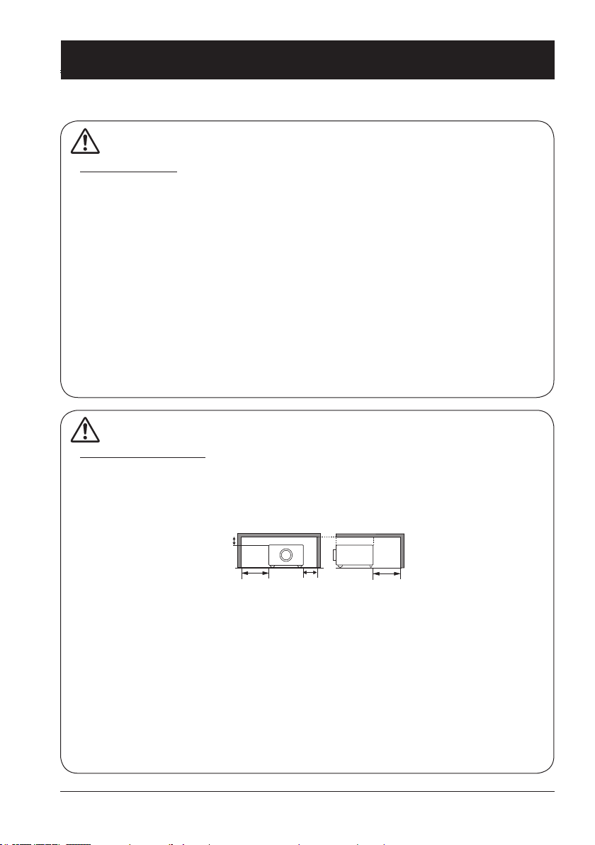
Caution
Safety precautions:
●GROUND your projector.
●Lens of your projector projects strong light. DO NOT look at the light beam directly. You
may get your eyesight hurt. This is especially the case with children.
●Unplug the AC power plug if your projector will not be used for long time.
●DO NOT overload the socket of power cord as it may lead to re or electric shock. DO
NOT subject the power cord to any object. DO NOT place your projector in locations
where its power cord may become damaged by treading by passersby.
●Disconnect the power plug before cleaning your projector. DO NOT apply liquid or sprays
to your projector. DO NOT wipe your projector with wet cloth.
●Please follow warnings and instructions given in labels attached to your projector. Unplug
your projector when your projector is exposed to thunderstorm weather, is unmanned, or
not in use for long periods to prevent damage caused by lightning and power surges.
●DO NOT use accessories without recommendation by the manufacturer as it may result in
potential risks.
Caution
Precautions on air outlet:
●Keep adequate clearance around your projector for its ventilation and cooling. See gure
below for the least clearance requirements. The least clearance is a MUST when your projector is placed within a cabinet or other closed environment.
Sides and bottom Rear
●DO NOT cover the air outlet of your projector. Poor ventilation not only shorten life cycle of
your projector but also may lead to risks.
●Slots and openings at rear and bottom of your projector are designed for ventilation. Keep
your projector from overheated to ensure its steady operation.
●DO NOT cover the air outlet with cloth or other objects. DO NOT place your projector on the
surface of bed, sofa, carpets, or similar object as this may block the air outlets at its bottom.
●DO NOT place your projector in closed environment, e.g. a bookcase, unless it is well venti-
lated.
● Keep any matter from falling in your projector through the air outlets as they may touch high
voltage parts and lead to re or electric shock by short circuits. DO NOT splash liquid to
your projector.
5
Page 6
Safety operation guideline
Note:
Precautions on location of your projector:
●Place your projector in a proper location or it may result in re.
●DO NOT expose your projector in rain or high humidity environments or it may result in re or
electric shock. DO NOT your projector near water or splashing water. DO NOT place any water
container, e.g. ower vase, atop your projector.
●DO NOT place your projector in environments of soot, moisture or smoke, e.g. your kitchen,
or it may lead to product failure or accidents. Your projector may be damaged by contact with
oil or chemicals.
●DO NOT place your projector near exhaust pipe or air conditioning equipment.
●DO NOT place your projector near radiator or heating pipes.
●DO NOT place your projector atop unstable truck, rack, or table. It may fall of the surface and
lead to personal injuries and property damages. Please use cart or rack recommended by the
manufacturer or included with your product. Please follow steps given in installation guideline
included with the wall and ceiling mount racks for installation. Use installation components
approved by the manufacturer.
●Be careful when moving your projector with cart. Abrupt stops, pushing too hard and rugged
surfaces may topple your projector and the cart together.
FOR EU USERS
The symbol mark and recycling systems described below apply to EU countries and do not
apply to countries in other areas of the world.
Your product is designed and manufactured with high quality materials and components
which can be recycled and/or reused.
The symbol mark means that electrical and electronic equipment, batteries and accumulators,
at their end-of-life, should be disposed of separately from your household waste.
Note:
If a chemical symbol is printed beneath the symbol mark, this chemical symbol means
that the battery or accumulator contains a heavy metal at a certain concentration.
This will be indicated as follows: Hg: mercury, Cd: cadmium, Pb: lead In the European
Union there are separate collection systems for used electrical and electronic equipment, batteries and accumulators.
Please, dispose of them correctly at your local community waste collection/recycling centre.
Please help us to conserve the environment we live in!
Caution:
Contains mercury
For more information on safe handling procedures, the measures to be taken in case of accidental breakage and safe disposal options visit: ec.gc.ca/mercure-mercury/
Dispose of or recycle in accordance with applicable laws.
6
Page 7
Safety operation guideline
Note:
Precautions on using your projector:
●DO NOT project the same image for long time as residual images may be left in the panel.
This is a property of LCD panel.
●Use power as indicated in tags attached to your projector. If you have doubts over available
power type, consult your dealer or local power company rst.
●DO NOT open or remove the casing for maintenance as this may lead to electric shock or
other damages. Call qualied maintenance personnel in case of any maintenance require-
ments.
– In case of the following, unplug the power cord and call qualied maintenance personnel
for service immediately:
a. Damaged or broken power cord or plug
b. Liquid splashed in your projector
c. Your projector exposed to rain or water
d. If your projector fails to work as expected by following operation instructions, adjust it ac-
cording to given instructions. Other invalid operations may damage your projector, which
requires the technician to spend more time before returning it back to normal.
e. The projector falls off to ground or its casing is damaged.
f. In case of any abnormal change in your projector during its use, then maintenance ser-
vices would be required.
●In case components replacement is required, make sure the replacements have been ap-
proved by the manufacturer and features the same with the one being replaced. Use of
unauthorized parts may lead to re, electric shock or personal injury.
●After the completion of maintenance or repair work, get the maintenance personnel to run
routine safety check to ensure your projector’s safety operation status.
Information for users in the European Union
This is a device to project images onto a screen, etc., and is not intended for use as indoor lighting in a
domestic environment. Directive 2009/125/EC.
NOTE FOR CUSTOMERS IN THE US
Hg LAMP(S) INSIDE THIS PRODUCT CONTAIN MERCURY AND MUST BE RECYCLED OR DISPOSED
OF ACCORDING TO LOCAL STATE OR FEDERAL LAWS.
7
Page 8
Safety operation guideline
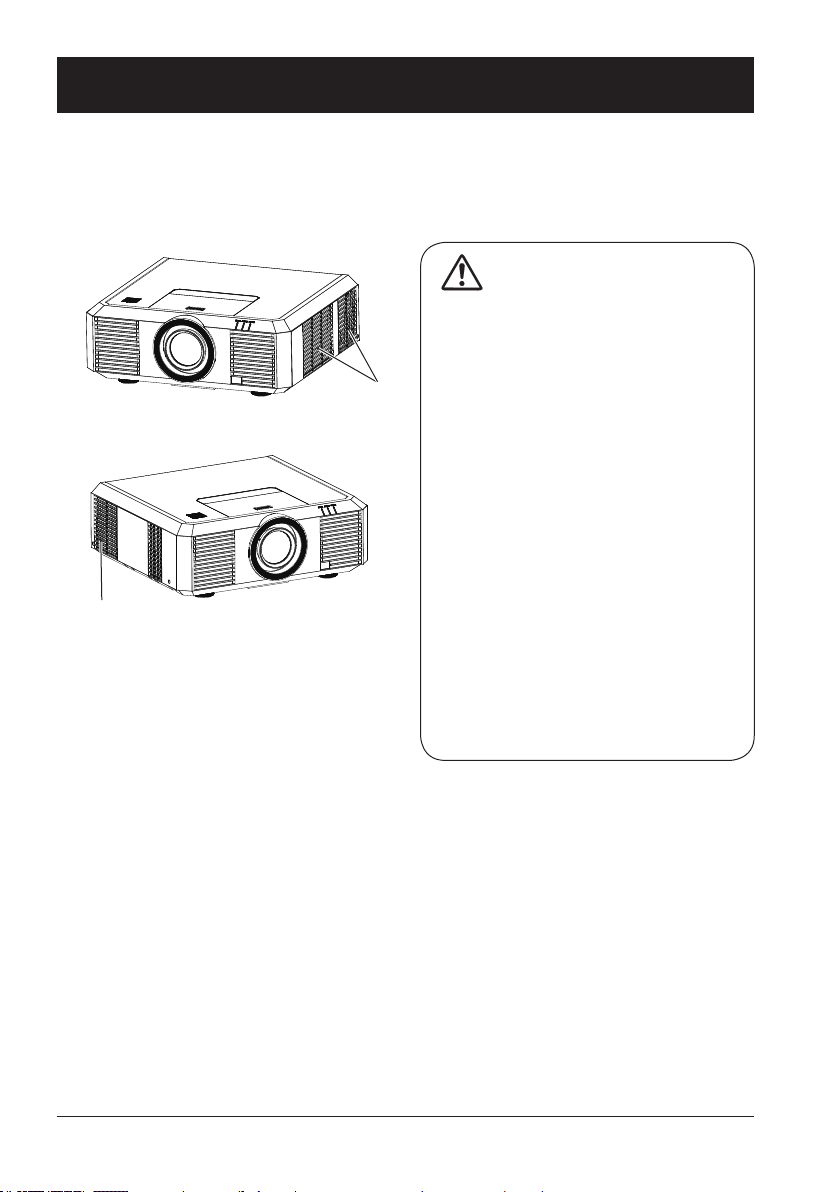
Air ventilation
Openings in the casing are designed for ventilation and overheating prevention. DO NOT block or
cover these openings to keep your projector in normal operation and from overheating.
Note:
Heat exhaust at the air outlet Keep the
following in mind when using or installing
your projector:
Air intake
Air outlet
(For heat exhaust)
– DO NOT place ammable materials or
sprayers near your projector.
– Keep the air outlet one meter away
from other objects.
– DO NOT touch the area close to the air
outlet especially the metal components,
e.g. screws. This area and parts will get
very hot once your projector starts operating.
– DO NOT place any object atop your
projector. They may not only be dam-
aged but also lead to re after being
overheated.
Cooling fans are designed for cooling
your projector. Fan speed is auto adjusted
subject to internal temperature of your
projector.
8
Page 9
10
10
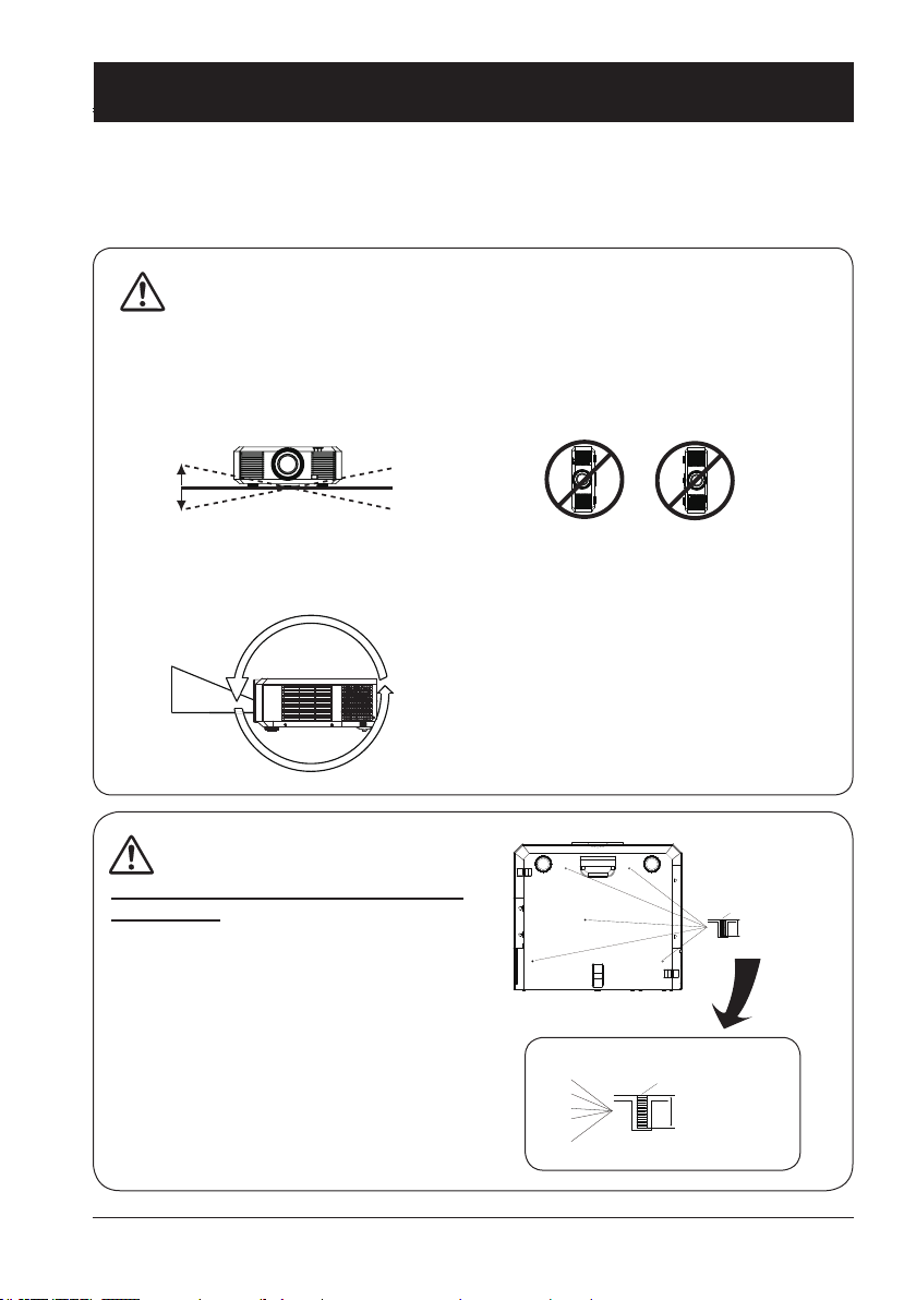
Safety operation guideline
Place your projector correctly
Use your projector at specified location in correct way. Invalid projector location may shorten
life-cycle of lamps or even lead to severe incidents or re.
Note:
Enable the “Ceiling” function if ip over screen is required.
•
DO NOT install your projector in ways as illustrated below.
DO NOT incline your projector
more than ±10 degrees.
0
0
The projector supports 360° projection in Vertical.
360°
DO NOT place your projector as
illustrated above.
Note:
Precautions on ceiling mount racket
installation:
●Get qualied technician to install the ceiling
mount racket.
●Warranty of your projector does not cover
hazards and damage caused by using ceiling mount rackets provided by unauthorized
dealers.
●Remove the ceiling mount racket when it is
not in use.
●Apply torque driver instead of power driver or
impact driver in your projector.
M6x10
10mm
M6x10
10mm
9
Page 10
Safety operation guideline
Moving your projector
When moving your projector close its adjustment legs as they may damage the lens and casing.
Keep your projector in suitable box when it is not to be used for a long time.
Note:
Precautions on moving or shipping your projector:
●DO NOT drop or impact your projector as it may get damaged or failed in operation.
●Please employ proper container for movement.
●Prohibit express or other shipping service provider personnel from shipping your projector
with improper boxes. Your projector may become damaged. Please consult your dealers
for shipping your projector by express or other shipping service providers.
●Place your projector in box only after it has been fully cooled down.
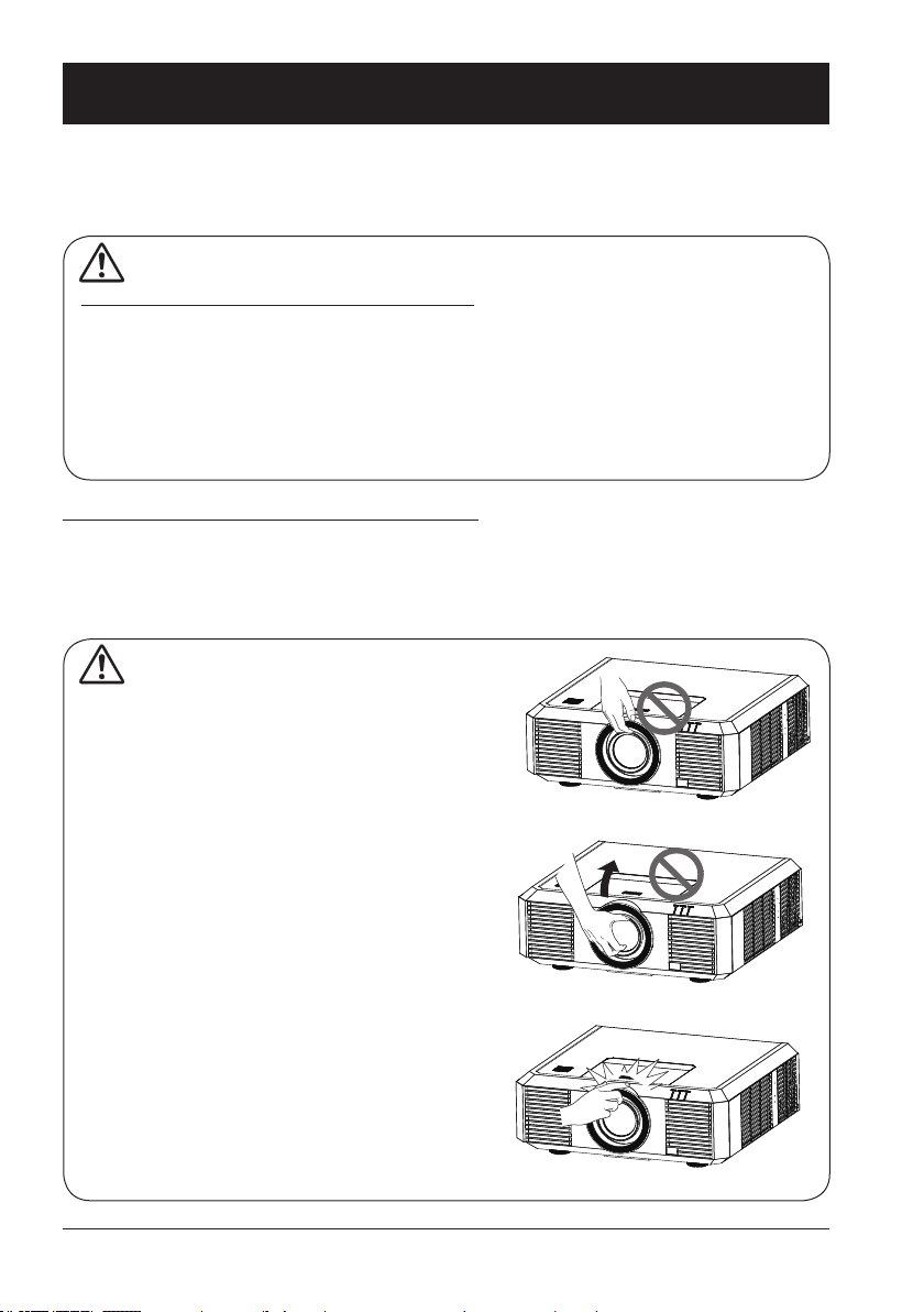
Precautions on dealing with your projector:
DO NOT lift or move your projector by holding the lens or projecting decoration ring as it may
damage the lens and your projector.
Be careful when handling your projector. DO NOT drop it, subject it to external forces, or place objects atop it.
Note:
Lens or your projector is electric powered.
Precautions on using your projector:
●DO NOT touch the lens when it is working
as your ngers may get hurt.
●DO NOT let children touch the lens.
10
DO NOT hold the lens or area around it.
Page 11
Compliance
ASA
FCC Caution
Declaration of Conformity
This device complies with Part 15 of the FCC Rules.
Operation is subject to the following two conditions:
(1) This device may not cause harmful interference, and (2) this device must accept any interference
received, including interference that may cause undesired operation.
To assure continued compliance, follow the attached installation instructions and do not make any
unauthorized modications.
CAUTION:
This equipment has been tested and found to comply with the limits for a Class A digital device, pursuant
to part 15 of the FCC Rules. These limits are designed to provide reasonable protection against harmful
interference when the equipment is operated in a commercial environment. This equipment generates,
uses, and can radiate radio frequency energy and, if not installed and used in accordance with the
instruction manual, may cause harmful interference to radio communications. Operation of this equipment
in a residential area is likely to cause harmful interference in which case the user will be required to
correct the interference at his own expense.
Model Number : EK-500U
Trade Name : EIKI
Responsible party : EIKI International, Inc.
Address : 30251 Esperanza Rancho Santa Margarita CA 92688-2132
Telephone No. : 800-242-3454 (949-457-0200)
AC Power Cord Requirement
The AC Power Cord supplied with this projector meets the requirement for use in the country you purchased it.
AC Power Cord for the United States and Canada:
AC Power Cord used in the United States and Canada is listed by the Underwriters Laboratories (UL)
and certied by the Canadian Standard Association (CSA).
AC Power Cord has a grounding-type AC line plug. This is a safety feature to be sure that the plug will
t into the power outlet. Do not try to defeat this safety feature. Should you be unable to insert the plug
into the outlet, contact your electrician.
AC Power Cord for the United Kingdom:
This cord is already tted with a moulded plug incorporating a fuse, the value of which is indicated on
the pin face of the plug. Should the fuse need to be replaced, an ASTA approved BS 1362 fuse must
be used of the same rating, marked thus
the cover omitted. If a replacement fuse cover is required, ensure it is of the same colour as that visible
on the pin face of the plug (i.e. red or orange). Fuse covers are available from the Parts Department
indicated in your User Instructions.
If the plug supplied is not suitable for your socket outlet, it should be cut off and destroyed.
The end of the exible cord should be suitably prepared and the correct plug tted.
WARNING : A PLUG WITH BARED FLEXIBLE CORD IS HAZARDOUS IF ENGAGED IN A LIVE
SOCKET OUTLET.
The Wires in this mains lead are coloured in accordance with the following code:
Green-and-yellow ...... . Earth
Blue . . . . . . . . . . . . . . . . Neutral
Brown............... Live
As the colours of the wires in the mains lead of this apparatus may not correspond with the coloured
markings identifying the terminals in your plug proceed as follows:
The wire which is coloured green-and-yellow must be connected to the terminal in the plug which is
marked by the letter E or by the safety earth symbol
The wire which is coloured blue must be connected to the terminal which is marked with the letter N
or coloured black.
The wire which is coloured brown must be connected to the terminal which is marked with the letter L
or coloured red.
WARNING: THIS APPARATUS MUST BE EARTHED.
. If the fuse cover is detachable, never use the plug with
or coloured green or green-and-yellow.
THE SOCKET-OUTLET SHOULD BE INSTALLED NEAR THE EQUIPMENT AND EASILY ACCESSIBLE.
11
Page 12
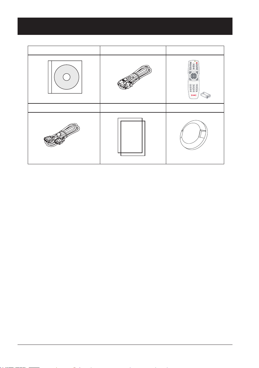
Accessories
Owner's Manual(CD) AC Power cord
US Type x1
Euro Type x1
VGA cable Quick start guide Lens Cover
Remote control with batteries
(AA or LR6)
12
Page 13

Overview
This chapter presents names and
functions of individual component.
Page 14
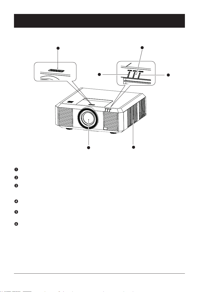
Front/top
Name and function of your projector
6
5
1
4
2
Projection lens
Air intake with lter
POWER indicator (Refer to Page 73)
– The power indicator turns steady red when your projector is in standby mode
– It turns steady green when your projector is in normal operation
STATUS indicator (Refer to Page 73)
It ashes red when internal temperature of your projector is out of operation range
FILTER indicator (Refer to Page 73)
It turns red when the lter needs be replaced
Lens release button
3
14
Page 15
Rear
1
3
4
5
6
8
141.7
AUDIOAUDIO
IN2
AUDIO
IN1
AUDIO
OUT
S-VIDEOVIDEO R/CINR/C
OUT
RS-232C
DVI-D
P/PR
MONITOR OUT
VGA
IN
G/Y B/PB H/HV V
2
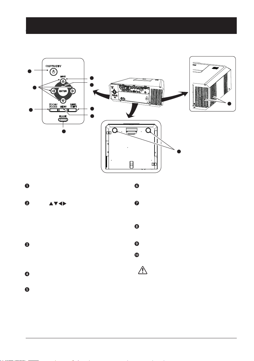
Name and function of your projector
VOL- VOL+
7
ON/STAND-BY
Power on or off your projector
Arrow
– Select items or adjust values in the
OSD menu.
– Select display area in digital zoom+
mode
– Adjust the volume.
ZOOM/FOCUS
– Enter the optical zoom adjustment
mode
– Enter the focus adjustment mode
BLANK
Dark out screen images temporarily
MENU
Open or close the OSD menu
9
10
LENS SHIFT
Enter the lens moving mode
ENTER
Enter the OSD menu or select options in
a menu
INPUT
Select source of input
Air exhaust
Adjustment pad
Note:
Air outlet emits hot air. DO NOT place
heat sensitive objects near it.
15
Page 16
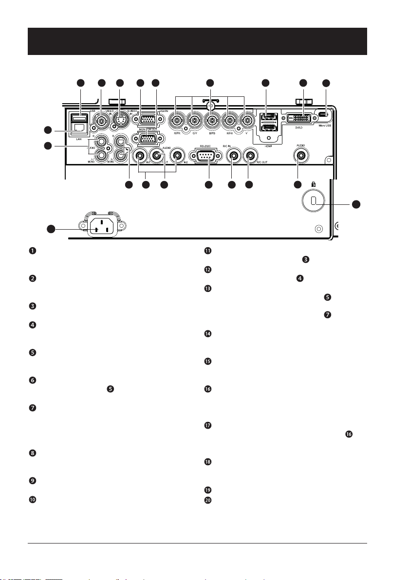
Terminal
9
2345678
1
11
Name and function of your projector
10
13 14 15 16
12
19
LAN
Connect network cable to this port for controlling
and operating your projector via network.
USB
When using the Memory Viewer function, insert
the USB memory directly to this terminal.
VIDEO IN
Connect video output signal to this terminal.
S-VIDEO IN
Connect S-VIDEO output signal of video device to
this terminal.
VGA IN
Connect output signal from computer to this
terminal.
MONITOR OUT
Transmit signals from to other displays when
your projector is acting as a display output.
R(PR)/G(Y)/B(PB)/H(HV)/V
– Connect RGBHV format (5-core) signals to
R/G/B/HS/VS terminal respectively.
– Connect component signals to Y, Pb, Pr termi-
nal respectively.
HDMI
Connect HDMI digital output signals to this
terminal.
DVI-D IN(HDCP)
Connect DVI digital output signals to this terminal.
Micro-USB
The terminal is to use the USB display function,
when connecte the projector to computer with
USB cable
1817
AUDIO (Video)
Connect audio signal from to this terminal.
AUDIO (S-Video)
Connect audio signal from to this terminal.
AUDIO IN1/AUDIO IN2
– Connect audio signals for device to
AUDIO IN1
– Connect audio signals for device
AUDIO IN2
to
AUDIO OUT
Output audio signals to amplier or other audio
equipment.
SERIAL
Connect serial cable to this terminal when using
RS232 device to control or operate your projector.
REMOTE IN
Connect wired remote controller to this terminal.
Connection of a wired remote controller will disable the wireless one.
REMOTE OUT
Transmit wired remote controller signals of to
another projector when a wired remote controller
is used.
AUDIO/DVI-D
Connect audio signals of DVI equipment to this
terminal.
Power cord connector
Anti-theft slot
20
16
Page 17
Name and function of your projector
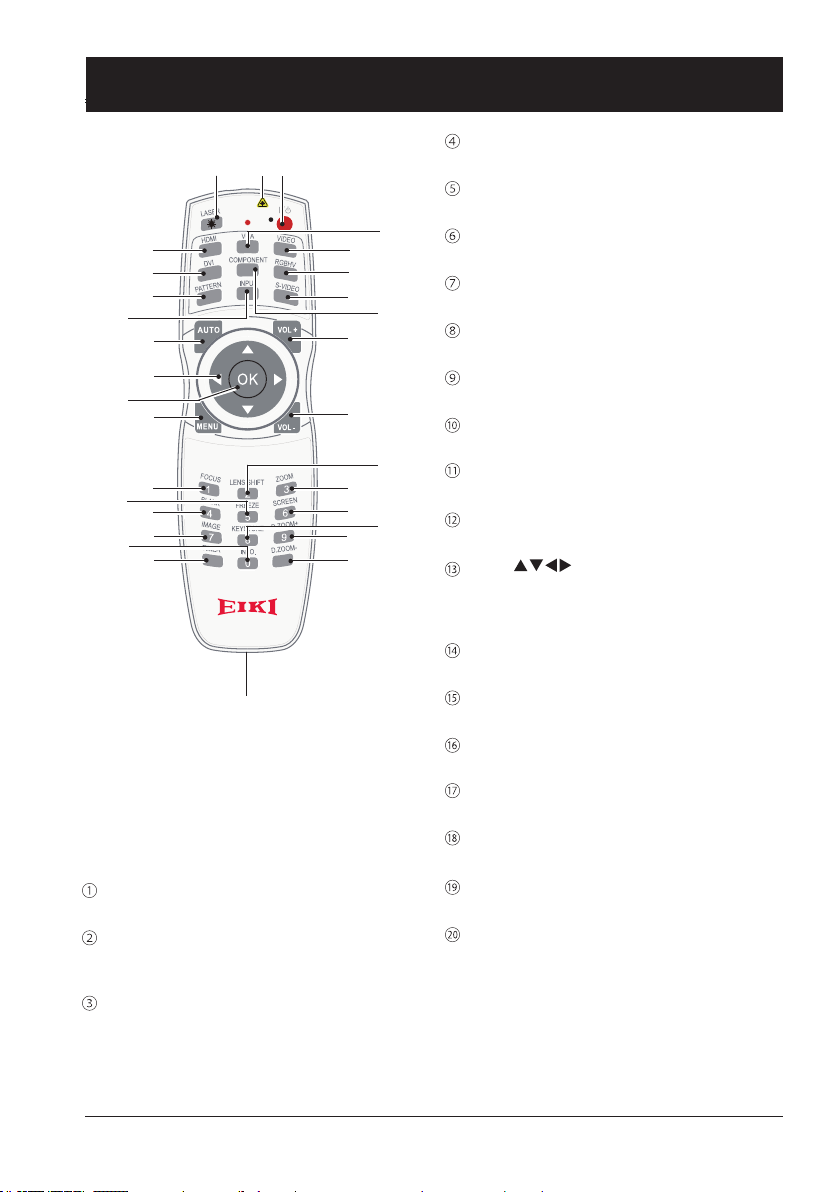
Remote controller
②
③
④
⑤
⑪
⑫
⑬
⑭
⑮
⑱
㉓
⑲
⑳
㉕
㉑
*
Laser Transmitting Window:
Laser beam will emit from this window while
pressing LASER button during the projection
to use the remote controller as a laser pointer.
Do not stare directly at the laser transmitting
window or aim the window at human body, to
avoid any physical injury.
POWER
Power on or off your projector.
LASER
Press the LASER button during presentation to
use the remote controller as laser pointer
HDMI
Select HDMI input source
①
*
⑥
⑦
⑧
⑨
⑩
⑯
⑰
㉒
㉖
㉗
㉔
㉘
㉙
㉚
DVI
Select DVI input source
PATTERN
Select built-in test pattern of your projector
VGA
Select VGA input source
VIDEO
Select VIDEO input source
RGBHV
Select RGBHV input source
S-VIDEO
Select S-VIDEO input source
COMPONENT
Select Component input source
INPUT
Open or close the INPUT menu
AUTO
Enter auto adjustment mode
Arrow
– Select items or adjust values in the OSD
menu
– Select display area in digital zoom+ mode
OK
Enter the OSD menu or select options in it
MENU
Open or close the OSD menu
VOLUME +
Increase volume
VOLUME -
Decrease volume
FOCUS
Enter the focus adjustment mode
BLANK
Dark out screen images temporarily
IMAGE
Select image mode
17
Page 18
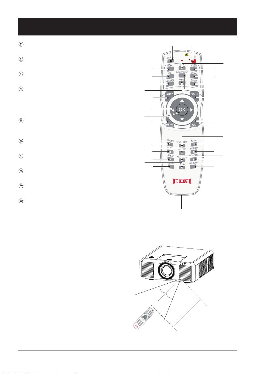
Name and function of your projector
TIMER
Enable the timer function
LENS SHIFT
Enter the lens moving mode
FREEZE
Freeze projected images
KEYSTONE
Keystone calibration
The keystone calibration mode changed as:
H/V Keystone -> Corner Keystone -> H/V
Keystone -> ....
INFO.
Display current status information of your projector
ZOOM
Enter the zooming mode
SCREEN
Select screen size
D.ZOOM+
Zoom in projected image
D.ZOOM-
Zoom out projected image
Wired remote controller output terminal
Connect cable of wired remote controller to
this port while operating the projector by wired
remote control
②
③
④
⑤
⑪
⑫
⑬
⑭
⑮
⑱
㉓
⑲
⑳
㉕
㉑
①
*
⑥
⑦
⑧
⑨
⑩
⑯
⑰
㉒
㉖
㉗
㉔
㉘
㉙
㉚
Remote controller operation
range
Point your remote controller to the IR receiver
of your projector
Maximum operation range of your remote controller is an area of radius 5 meters and arc 60°
in front of and behind your projector
18
30°
30°
5m
Page 19
Name and function of your projector
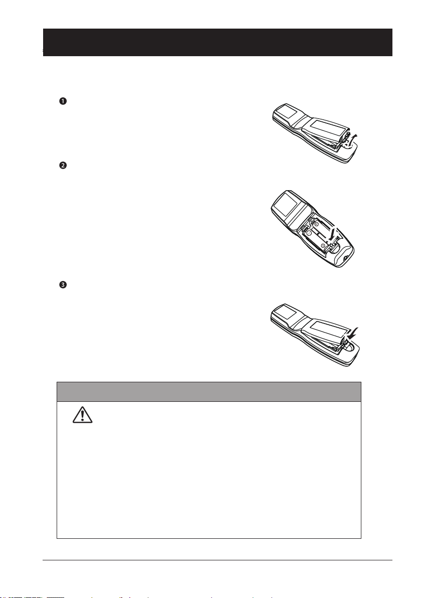
Install battery of remote controller
Open the battery cover.
Insert a new battery in it.
Two AA batteries
Place your batteries with its
anode and cathode (+ and -)
in correct direction. Keep both
poles in good connection to the
contacts within the compartment.
Put the cover back.
Please follow the following rules for safety operation:
● Use two of AA or LR6 alkaline batteries.
● Replace both batteries at the same time.
● Do not mix new and old batteries as one pair.
● Keep your remote controller away from water or other liquids.
● Do not expose your remote controller to environments with high
humidity or temperature.
● Do not drop your remote controller.
● In case of any battery solution leaking in the compartment, clear it
thoroughly before placing new batteries in it.
● Using battery of other types than what specied on this manual may
lead to risks of explosion.
● Please dispose your old battery by following instructions given in tag
of the battery or local regulations.
19
Page 20

Installation
This chapter introduces the information
of install.
Page 21
Installation
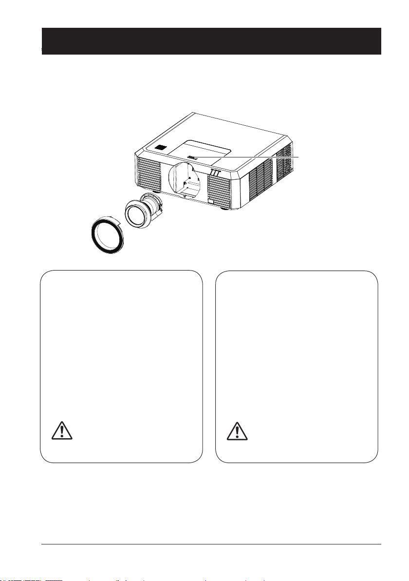
Lens installation
Please follow steps given below to install lens after its replacement or when optional ones are
employed. Please consult your dealers for details on optional lenses.
Lens release
button
Remove the lens
1 Center the lens with its movement func-
tion. (Hold 5 sec. on Lens Shift button.
Refer to the Page 30).
2 Power off your projector and unplug the
AC power cord.
3 Remove the decoration ring by turn it
counterclockwise.
4 Press and hold the lens release button
at top of the casing. Turn it counterclockwise until it sticks, and then pull it out of
your projector gently.
Note:
Be careful in removing the lens.
Do not drop it.
● Do not touch or remove any other component except the lens and parts related to it.
Otherwise, you may experience product failure, electric shock, re, or other incidents.
● Make sure model of the lens is compatible with your projector before installing it.
● For details on lens and its installation, please call local dealers.
Installing lens
1 Turn the lens counterclockwise and
remove its decoration ring.
2 Align the red mark on your lens and your
projector and insert the lens in the latter.
3 Turn the lens clockwise slowly until you
hear a click. Make sure the lens is fully
inserted in your projector.
4 Turn the lens decoration ring clockwise
to replace it.
Note:
Do not press and hold the lens
release button when installing it.
21
Page 22
Installation
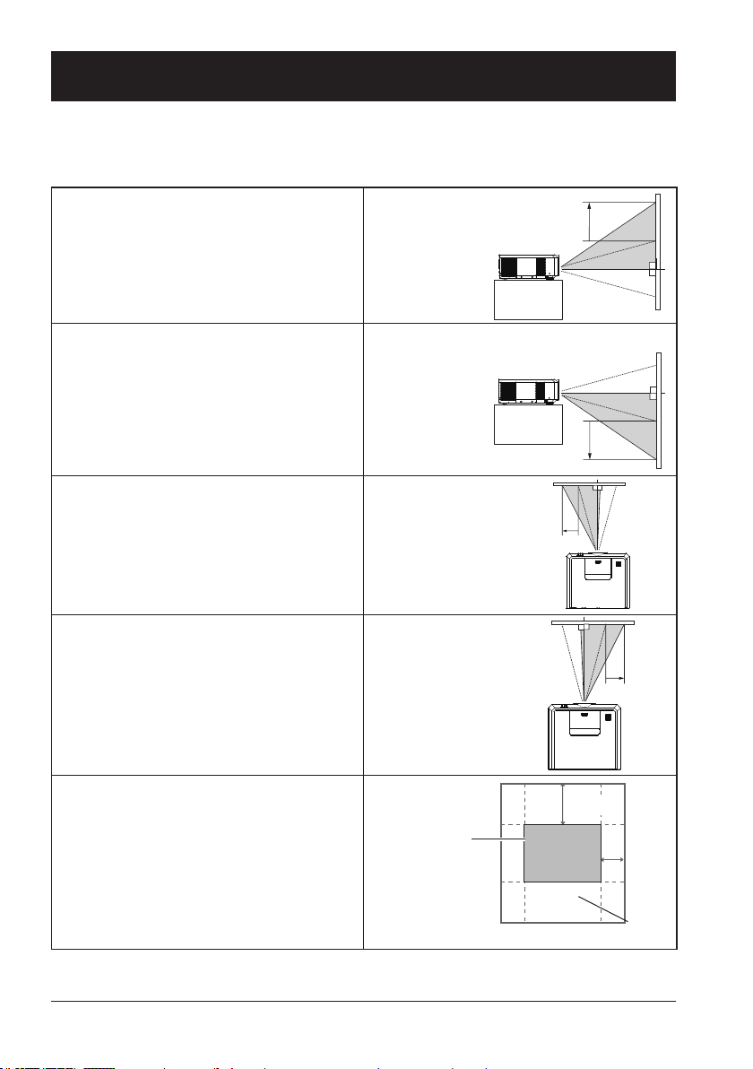
Lens shift adjustment
The electric lens shift function may adjust your lens in all four directions.
This function enables easy image position adjustment.
The projection location of your image may be
moved upward a distance up to 60% of the
length of the image.
The projection location of your image may be
moved downward a distance up to 60% of the
length of the image.
The projection location of your image may be
moved leftward a distance up to 30% of the
width of the image.
The projection location of your image may be
moved rightward a distance up to 30% of the
width of the image.
Move lens to it top
position
Move lens to it
bottom position
Move lens to it
leftmost position
Move lens to it
rightmost position
Center
the lens
Scope of lens shift adjustment
*This table is measured with standard lens.
*When the setting of LENS SHIFT as the maximum position, the corner of projection image might be darker.
22
60%
30%
Lens shift range
Page 23
Installation
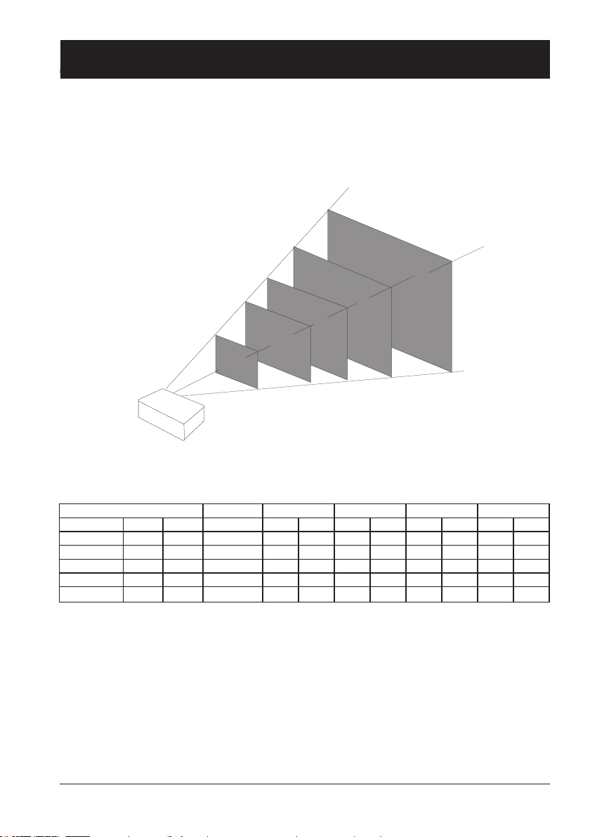
Set up your projector
● Ambient brightness may affect your projection image quality. For the optimal image effect, it is
recommended to control brightness in your environment.
● Values shown in gure below are approximates only. They may differ from the actual ones.
300"
200"
150"
100"
30"
EK-500U(16:10) Unit:cm
Lens Model No. AH-E22010 AH-E22020 AH-E21010 AH-E23010 AH-E23020
Screen size Width Height Distance Wide Tele Wide Tele Wide Tele Wide Tele
30 inch 64 40 50 68 97 89 164 151 271 256 452
100 inch 215 134 166 244 332 307 557 537 927 898 1541
150 inch 323 202 244 371 478 462 838 820 1395 1356 2312
200 inch 431 269 332 498 644 618 1119 1093 1863 1815 3093
300 inch
646 404 488 751 996 929 1681 1639 2800 2732 4654
23
Page 24
Installation
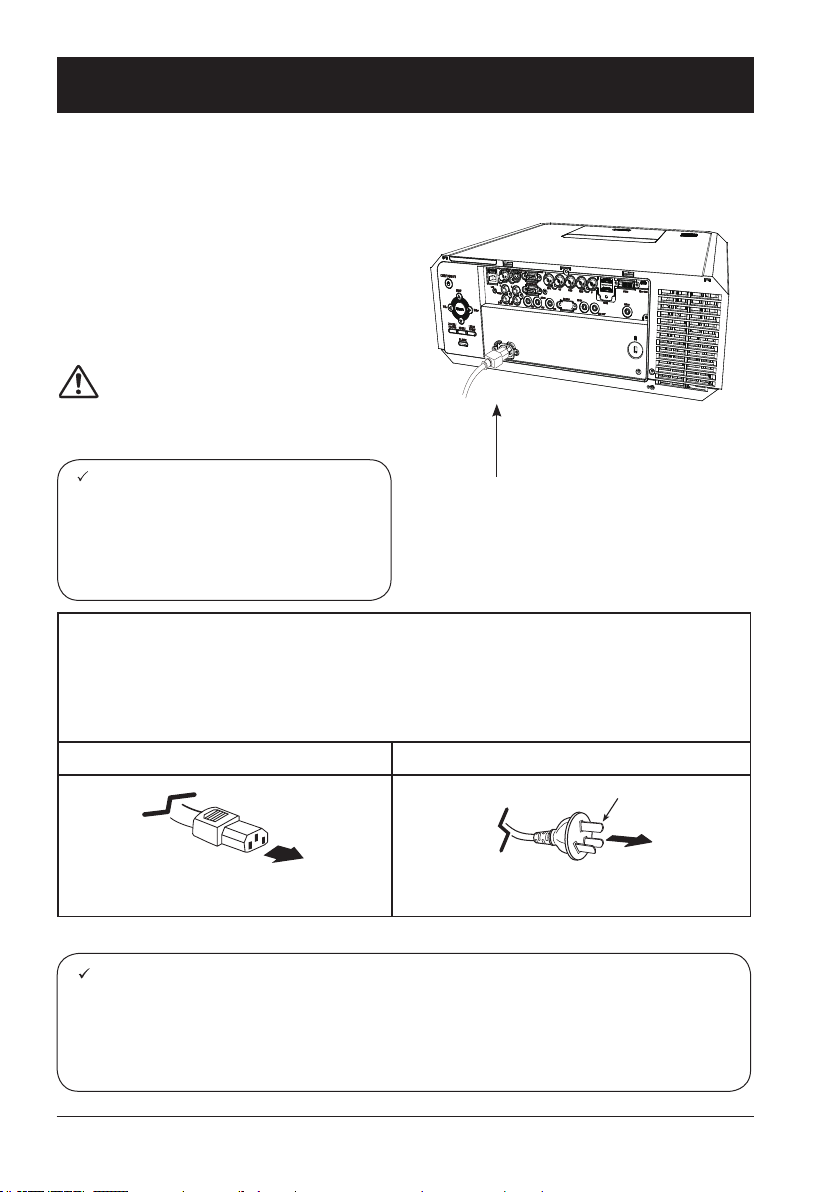
Connect the AC power cord
Standard voltage employed by your projector is AC 100-240V. It adapts to different input voltage
automatically. Your projector employs 2-phase power cord with neutral ground cable.
Do not use any other type of power cords or you
may face the risks of electric shock. In case you
have any doubt on type of power cord you are
using, please call authorized dealer or service
center for help. Before powering on your projector, get all external equipment connected in
advance.
Note:
Keep your AC power socket close to your
projector for easy plugging and unplugging.
Note:
For safety reasons, unplug the AC power cord when your projector is not in
use. Your projector will consume a small
amount of power when it is connected to
AC grid power and in standby mode.
Precautions on power cord
Your AC power cord should meet regulations of the country/district where your projector is
used.
Please make sure the type of the power plug is compliant with those given in gure below.
Make sure you are using a valid AC power cord.
In case the included AC power cord does not comply with the AC power socket in your location, call your dealer for replacement.
The projector side Connect to the AC power socket
Connect to power cord connector of
your projector
Note:
● Use of invalid power cord may hamper product performance or even lead to electric
shock, re, and other incidents. Please use power cord compliant with the included one
to ensure product performance and operation safety.
● The frequently used cables are: AC power cord, VGA cable, audio cable, video cable,
and RS232 control cable.
Connect included AC power
cord to your projector.
Grounding end
Connect to AC power socket
24
Page 25
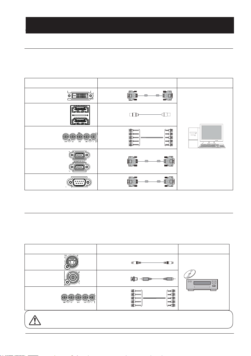
Connection to equipment
Connection to computer
Cables for connection:
● VGA cable ● DVI cable* ●
● BNC cable* ● HDMI cable*
(* This cable is optional. )
RS232 control
cable*
Ports on your projector Connection
DVI-D(HDCP)
HDMI
R(PR) / G(Y) /
B(PB) / H(HV) / V
VGA IN
MONITOR OUT
RS232C
DVI cable
HDMI cable
BNC cable
VGA cable
RS232
control cable
cable
Connect to video equipment
Cables for connection:
● S-VIDEO cable* ● VIDEO cable*
● BNC cable*
(* This cable is optional.)
Ports on your projector Connection cable Equipment
Equipment
S-VIDEO IN
VIDEO IN
R(PR) / G(Y) /
B(PB) / H(HV) / V
Unplug power cords of your projector and all external equipment before connecting
any cable to them.
S-VIDEO cable
VIDEO cable
BNC cable
25
Page 26
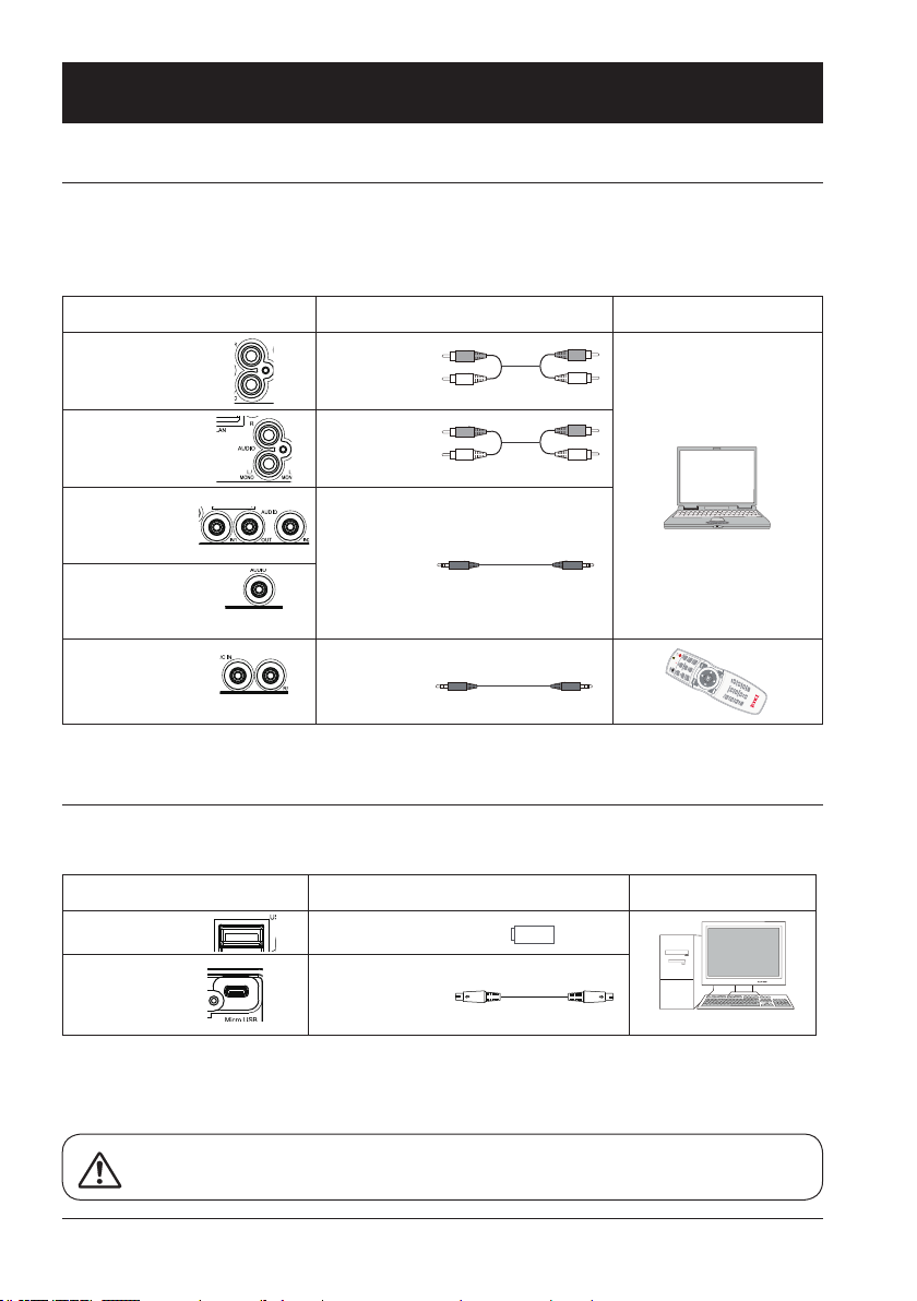
Connection to equipment
Connection to audio equipment
Cables for connection:
●
Audio cable*
(* This cable is optional.)
Ports on your projector Connection cable
MONO L/R
AUDIO IN
AUDIO IN / OUT
AUDIO DVI-D
REMOTE IN/OUT
Audio cable
Audio cable
Audio cable
Audio cable
Connection to USB equipment
Cables for connection:
●
USB cable*
(* This cable is optional.)
Ports on your projector Connection cable Equipment
USB
Appareil USB-A
Equipment
Micro USB
26
Câble USB
Unplug power cords of your projector and all external equipment before connecting
any cable to them.
Page 27

Operation
This chapter introduces you to basic
operation of your projector.
Page 28

Basic operation
141.7
AUDIOAUDIO
IN2
AUDIO
IN1
AUDIO
OUT
S-VIDEOVIDEO R/CINR/C
OUT
RS-232C
DVI-D
P/PR
MONITOR OUT
VGA
IN
G/Y B/PB H/HV V
Power on your projector
Power
VOL- VOL+
Power
1. Connect all external equipment to your projector (e.g. computer or camera) before powering it
on.
2. Connect AC power cord of your projector to an AC power socket. The Power indicator turns on
in red.
3. Press the Power button on the rear control panel or the remote controller.
The Power indicator lights in green and the cooling fan starts running.
4. If your projector is setting as password protected, the password dialog box displays. Enter your
password as instructed below.
Enter password (PIN)
Press button to select a number, press button to enter it and move the cursor. The number you
typed is displayed as “ ”. To edit number you have entered, press button to move the cursor to the
number you want to change, press button to select the correct one.
Repeat this step to type in a 3-digit number.
Move the cursor to OK after you have typed
the 3-digit number. Press the ENTER button
and now you are ready to use your projector.
If the password is invalid, the password displayed as “
” will be in red. Please try again
with a valid one.
Note:
● In case the “Logo Select” option is set
to OFF, then no welcome image will
display in screen.
● You can do nothing but powering off
your projector during the welcome
image is displaying.
28
What is a password (PIN)?
A password (PIN) is an ID code for identifying people with knowledge about it to operate your projector. A password (PIN) setting may help preventing your projector from
unauthorized use.
You password (PIN) code is a 3-digit number. To find out more about protecting your
projector with a password (PIN), please refer to the PIN Code Lock function in the
Setup menu on Page 54 for details.
Precautions on password (PIN) operation
You cannot operate a password (PIN) protected projector without correct password
(PIN) Please set up a new password (PIN) and keep your operation manual in safe
place. In case the password (PIN) is lost or forgotten, call your dealer or service center.
Page 29

141.7
AUDIOAUDIO
IN2
AUDIO
IN1
AUDIO
OUT
S-VIDEOVIDEO R/CINR/C
OUT
RS-232C
DVI-D
P/PR
MONITOR OUT
VGA
IN
G/Y B/PB H/HV V
Basic operation
Power off your projector
1. Press the Power button at the rear control
panel or the remote controller, the “Power
off?” message displays.
2. Press the Power button again in 4 seconds
after the “Power off?” message prompted
to you. The POWER indicator ashes red
while the cooling fan continues running.
(You may set up noise level and speed of
the fan.) Unplug the power cord until the fan
stops running. Failure to do so may shorten
life cycle of your projector or lead to power
on failures or operation abnormalities.
3. The POWER indicator stops ashing once
the projector has been cooled down to
ready for power on again.
To maintain the life cycle of the lamp,
power off your projector after it has
been turn on for at least ve minutes.
Do not use your projector without
stop. As it may hurt the life cycle of
your lamp. Power off your projector at
least once every 24 hours and have
it idle for an hour.
Power
VOL- VOL+
Power
Power off?
“Power off?” message disappears
in 4 seconds.
Note:
● If the “On Start” function is set to “On”, your projector will power on once it is connected to an
AC power socket. (Refer to page 53)
● Speed of the cooling fan varies with internal temperature of your projector.
● Do not place your projector in any box before it is fully cooled down.
● In case the POWER indicator flashes or turns red, refer to the “Light indicator status” for
instructions. (Refer to page 69)
● The POWER indicator flashes when the lamp is cooling down. Do not power on your projector
at this time. Power on your projector only after the POWER indicator turns red.
● Unplug the power cord after your projector has been turned off. The fan stops running.
● The POWER indicator turns red when your projector is ready for power on again. It takes less
time to restart your projector after it was powered off in the standard power off procedure than
that of the non-standard one.
29
Page 30

设置
Setting
1/5
Off
Auto PC adj. On
Off
141.7
VOL- VOL+
AUDIOAUDIO
IN2
AUDIO
IN1
AUDIO
OUT
S-VIDEOVIDEO R/CINR/C
OUT
RS-232C
DVI-D
P/PR
MONITOR OUT
VGA
IN
G/Y B/PB H/HV V
Basic operation
Auto setup
ZOOM/FOCUS
LENS SHIFT
Zoom /focus function
1. Press the ZOOM / FOCUS button on the
rear control panel or remote controller for
zooming and focusing.
2. Press
button to zoom in and out.
Press button to change focus of
image. Default adjustment speed is set to
FAST. You may press the ENTER button,
select STEP for speed fine-tuning.
Lens movement adjustment
1. Press the LENS SHIFT on the rear control
panel or remote controller to adjust position of the lens. Default adjustment speed
is set to FAST. You may press the ENTER
button, select STEP for speed fine-tuning.
2. Movement of the lens is shown on the
screen. Press
screen to required location without any
image distortion. Range of screen movement - Upward or downward from the lens
movement axis: 60%. Leftward or rightward: 30%.
3. Press and hold the LENS SHIFT button on
the rear control panel or remote controller
for 5 seconds to home it to the center
position.
button to move the
FOCUS
LENS SHIFT
ZOOM
Zoom / focus
ZOOM
FOCUS
FAST
SELECT : ENTER
Lens movement
LENS
SHIFT
FAST
SELECT : ENTER
Note:
The arrow mark displays in black when
the lens is not moved. It turns red once
the lens is moved for adjustment.
Auto setup function
Press the AUTO button on your remote controller to auto execute settings given in the
Auto Setup menu (including Auto Searching,
Auto PC Adjusting and Auto Keystone).
30
Auto setup
Input search
Auto Keystone
设置
Setting
1/5
Auto setup
Input search Off
Auto PC adj. On
Auto Keystone Off
Page 31

Basic operation
Adjustment pad
You may use the adjustment leg to raise your projector up to 5.0 degree.
Turn the pad to tilt your projector to required height.
To raise your projector, turn both pads clockwise.
To lower down your projector or close the pad, turn
both pads counterclockwise.
You may use the auto setup function to adjust your
projector’s keystone distortion automatically or do
this with the remote controller or OSD menu manually.
Keystone adjustment
You may adjust keystone distortion of image in your projector with the V keystone adjustment.
Follow steps below to adjust keystone distortion of projected image manually.
Press the KEYSTONE button on your remote controller.
The keystone adjustment dialog box displays, press
button to adjust keystone distortion. You may save your
settings for keystone adjustment.
Press
button to narrow upper part of the image
Adjustable
pad
Keystone
adjustment
Press button to narrow lower part of the image
Keystone adjustment
● The arrow mark looks white when there is no keystone adjustment in existence.
● The arrow mark indicating the adjustment direction turns red.
● The arrow mark disappears when the maximum adjustment limit reaches.
● The keystone adjustment will be canceled if you press the keystone adjustment button when it is
displaying.
● The adjustable range is subject to source of signal input.
31
Page 32

Menu item overview
① ② ③ ④
Basic operation
⑥ ⑦
⑤
Main menu
Submenu
Auto PC adj.
Fine sync
H Position
V Position
H size
Aspect
Project way
Menu position
Background display
System
Display
Normal
Upper left
- - - -
Front
Blue
0
0
0
0
Display
Select Auto PC Adjust, Fine sync., H Position, V Position, H size, Aspect, Project way,
Menu position, Background display, System to align each parameter with VGA input
signal format.
Color adjust
The color adjust options are: Image mode (Cinema/ Blackboard(Green)/ Colorboard/
User Image/ Dynamic/ Standard), Contrast, Brightness, Color temp., Red, Green, Blue
and sharpness.
Setting
For computer input the setting options are: On start, Standby mode, High land, Lamp
control, Cooling fast, Key lock, Iris and Sound.
For video input the setting options are: On start, Standby mode, High land, Lamp control, Cooling fast, Closed caption, Key lock, Iris and Sound.
For HDMI input the setting options are: On start, Standby mode, High land, Lamp control, Cooling fast, Key lock, Iris, Sound and HDMI setup.
Expend
Setting the Language, Auto setup (Input search/ Auto PC adj./ Auto keystone), Keystone, Logo, Security, Power management, Filter counter, Test pattern, Remote control
and Factory default function as you need.
Memory Viewer
Setting the display method of Memory Viewer page as Set slide, Slide transition effect,
Sort order, Rotate, Best t, Repeat and Apply.
Network
Network function menu.
Information
Display information about the projector.
32
Page 33

How to use the OSD
141.7
AUDIOAUDIO
IN2
AUDIO
IN1
AUDIO
OUT
S-VIDEOVIDEO R/CINR/C
OUT
RS-232C
DVI-D
P/PR
MONITOR OUT
VGA
IN
G/Y B/PB H/HV V
Basic operation
Main menu
Auto PC adj.
Fine sync
H Position
V Position
H size
Submenu
Aspect
Project way
Menu position
Background display
System
Menu operation
1. Press the MENU button on the rear control
panel or remote controller and the OSD
displays.
2. Press
main menu item. Press button or OK
button to enter a submenu.
3. Press
menu, then press OK button or button to
set up or enter an option.
4. Press
navigate options, then press OK button to
act on the item and exit.
5. Press
Press the MENU button on remote controller or control panel to exit the OSD.
button to act on or select one
button to select required sub-
button to select settings or
button to return to mainmenu.
Display
Normal
Upper left
- - - -
VOL- VOL+
OK
Front
Blue
0
0
0
0
OK
Menu
Menu
33
Page 34

02
02
Basic operation
Remote controller operation
Use your remote controller for common operations.
Screen size selection (SCREEN)
Press the SCREEN button on remote controller
to select required screen size mode.
Digital Zoom (D.ZOOM+/-)
Press the D.ZOOM+/- button on remote con-
troller to enter the Digital Zoom mode.
*Only for input as VGA, RGBHV, and the
screen size setting as Normal or Wide.
Volume +/- (VOLUME +/-)
Increase or decrease volume.
Timer (TIMER)
Press the TIMER button on remote controller.
A timer animation (00:00) displays and starts
timing in format of (00:00-59:59).
Press the TIMER button again to stop timing.
Press the TIMER button again to disable the
timing function.
Blank
Timer
Volume +/-
Screen
D.Zoom +/-
:
Timer display
Freeze (FREEZE)
Press the FREEZE button on remote controller to freeze image on the screen. Press the
FREEZE button or any button to cancel the
freeze function.
Blank (BLANK)
Press the BLANK button on remote controller;
a blank screen displays to replace existing
image. Press the BLANK button or any other
button to restore the image.
Press the BLANK to toggle switch your screen
as shown below:
BLANK → Normal → BLANK → Normal → ......
34
Freeze
Blank Image
BLANK
The BLANK screen disappears if no
buttons are pressed in 4 seconds.
Page 35

Input selection
141.7
AUDIOAUDIO
IN2
AUDIO
IN1
AUDIO
OUT
S-VIDEOVIDEO R/CINR/C
OUT
RS-232C
DVI-D
P/PR
MONITOR OUT
VGA
IN
G/Y B/PB H/HV V
Input select
Direct Operation
Press HDMI, VGA, VIDEO, DVI, COMP ON EN T,
RGBHV, USB or S-VIDEO on the remote
control as input source.
Menu operation
1 Press INPUT button on the top control to
display the input select menu.
2 Press button to select VGA, RGBHV,
HDMI 1, HDMI 2(MHL), DVI, Component,
Video, S-viedo, Memory Viewer, Network or
USB Display, then press the OK button.
VGA
RGBHV
HDMI 1
HDMI 2(MHL)
DVI
Component
Video
S-video
When input source is from computer connected to VGA terminal with VGA cable, please
select "VGA".
When input source is from BNC
connected to RGBHV terminal
with BNC*5 cable, please select "RGBHV".
When input source is from
equipment connected to HDMI
terminal with HDMI cable,
please select "HDMI".
When input source is from
equipment connected to HDMI
terminal with HDMI cable,
please select "HDMI 2".
When input source is from
equipment connected to DVI
terminal with DVI cable, please
select "DVI".
Select it when the input source
is from the video equipment
connected to YCbCr terminal.
Select it when the video input
signal is connected to VIDEO
IN terminal.
Select it when the video input
signal is connected to S-VIDEO
IN terminal.
Remote control
VGA
COMPONENT
HDMI
DVI
PATTERN
Control Panel
INPUT
Input select menu
VGA
RGBHV
HDMI 1
HDMI 2(MHL)
DVI
Component
Video
S-video
Memory Viewer
Network
USB Display
VIDEO
RGBHV
S-VIDEO
INPUT
VOL- VOL+
Note:
- When the "Input search" function is set to "On" in the "Auto setup" function, the input signal will
be searched automatically.
35
Page 36

Input selection
141.7
AUDIOAUDIO
IN2
AUDIO
IN1
AUDIO
OUT
S-VIDEOVIDEO R/CINR/C
OUT
RS-232C
DVI-D
P/PR
MONITOR OUT
VGA
IN
G/Y B/PB H/HV V
Remote control
Memory Viewer
Network
USB Display
When input source is from
device connected to USB-A
terminal, please select "Memory
Viewer".
When input source is from
network connected to LAN
terminal with LAN cable, please
select "Network".
When input source is from
device connected to Micro-USB
terminal, please select "USB
Display".
Control Panel
INPUT
Input select menu
VGA
RGBHV
HDMI 1
HDMI 2(MHL)
DVI
Component
Video
S-video
Memory Viewer
Network
USB Display
INPUT
VOL- VOL+
Note:
- When the "Input search" function is set to "On" in the "Auto setup" function, the input signal will
be searched automatically.
- When signal is in "USB Display","Memory Viewer" and "Network", FREEZE, ASPECT, IMAGE,
AUTO SETUP and SCREEN function cannot work.
36
Page 37

Input selectiong
System selection
The scanning system and auto computer adjustment function may detect scores of signal format.
If a PC is selected as the input signal source, your projector will detect and adapt to its signal format automatically. Correct image can be displayed without any setup operation.
Your projector will display one of the following:
If your projector failed to identify
Auto
signals not shown in the signals
format table, the “Auto” message
will display in the System Signal
Format menu. The Auto PC Adjusting function will make necessary adjustment to your projector
to project valid images. If images
are displayed incorrectly, adjust it
manually.
No PC signals detected. Check
----the connection between PC and
your projector.
Select the computer system manually.
1 Press the MENU button on remote control-
ler and the OSD displays. Press
to point to the Display icon, press button
button
or OK button and the Display menu displays.
2 Press
Format, then press OK button.
3 Press
signal format, then press OK button to con-
button to select System Signal
button to select required system
rm your selection.
OSD menu
Auto PC adj.
Fine sync
H Position
V Position
H size
Aspect
Project way
Menu position
Background display
System
Display
The selected system displays in the
PC system menu.
Note:
Your projector may save data generated by the Auto PC Adjusting
function.
Normal
Front
Upper left
Blue
- - - -
0
0
0
0
Note:
The computer system menu will be disabled once HDMI or DVI has been selected.
37
Page 38

OSD Setting-Display
Auto PC Adjusting
The Auto PC Adjusting function may get Total Dots, Horizontal and Vertical position, Display area H,
and Display area V aligned with computer input.
Direct Operation
Press Auto button on the remote control to
launch the Auto PC Adj. function.
AUTO
Menu Operation
1 Press the MENU button on remote controller
and the OSD displays. Press
button to
select Display icon. Press button or OK
button and the Display menu displays.
2 Press
tion, press OK button to conrm your choice.
button to point to Auto PC Adj. op-
Auto PC adj.
Auto PC adj.
Fine sync
H Position
V Position
H size
Aspect
Project way
Menu position
Background display
System
Display
Display
Note:
● Fine sync, H and V position and H Size of certain computers may be fully adjusted by the
Auto PC Adjusting function. In case the post-adjustment image still looks incorrect, adjust
it again manually.
● The Auto PC Adjusting function will be disabled once 480i, 575i, 480p, 575p, 720p, 1035i
or 1080i has been selected in the system menu.
Normal
Front
Upper left
Blue
- - - -
0
0
0
0
38
Page 39

0
0
0
0
Normal
Front
Upper left
Blue
- - - -
OSD Setting-Display
Manual computer adjustment
The scan system of your projector may fail to detect signal format used by certain computers as
they opted some special signal format. The manual computer adjustment function of your projector
enables you to adjust individual parameter to align with most special signal format. Your projector
comes with up to storage area to keep parameters manually adjusted by you. You may save preferred settings for certain computers as required.
1 Press MENU button on the remote controller and the OSD displays. Press
Display icon, press button or OK button to conrm your selection.
2 Press button to select items for adjustment, press button or OK button to conrm your
selection. Press button to adjust settings.
Auto PC adj.
Adjust [Fine sync], [H Position], [V Position] and [H
Size] automatically.
Fine Sync
Eliminate ashes in image. Press
Total Dots.
H Position
Press
button to adjust horizontal position of
image.
V Position
Press
button to adjust vertical position of image.
button to adjust
Auto PC adj.
Fine sync
H Position
V Position
H size
Aspect
Project way
Menu position
Background display
System
H size
Adjust and minimize the effect of interference caused
by projection of patterns consisting of vertical stripes.
Aspect
Press
button to select the item to set the screen
size to t the image while maintaining the aspect ratio
of the input signal.
Normal... Projects the image at the maximum size while
maintaining the aspect ratio of the input
signal.
Wide.... Projects the image at 16:9 aspect ratio.
Auto PC adj.
Fine sync
H Position
V Position
H size
Aspect
Project way
Menu position
Background display
System
button to select
Display
Display
Normal
Front
Upper left
- - - -
Blue
0
0
0
0
39
Page 40

0
0
0
0
Normal
Front
Upper left
Blue
- - - -
OSD setting-Display
Project way
Press button to select the project way.
Front ........ Projects to front screen when projector is
front standing.
Rear ........ Projects to rear screen when projector is
front standing.
Ceiling/Front ..... Projects to front screen when
projector is in ceiling state.
Ceiling/Rear ..... Projects to rear screen when
projector is in ceiling state.
Auto Ceiling/Front: Projects to front screen when
projector is in ceiling state
automatically.
Auto Ceiling/Rear: Projects to rear screen when
projector is in ceiling state
automatically.
Menu position
Press button to select the position of the on
screen menu.
Upper left .... Menu locates on upper left of
the screen.
Upper right .. Menu locates on upper right of
the screen.
Center ......... Menu locates at the center of
the screen.
Lower left .... Menu locates on lower left of
the screen.
Lower right .. Menu locates on lower right of
the screen.
Background display
Press button to select thescreen background of
the projector when there is no signal detected.
Black .... Select black background.
Blue ...... Select blue background.
Display
Display
Normal
Upper left
- - - -
Auto PC adj.
Fine sync
H Position
V Position
H size
Aspect
Project way
Menu position
Background display
System
Auto PC adj.
Fine sync
H Position
V Position
H size
Aspect
Project way
Menu position
Background display
System
Front
Blue
0
0
0
0
Note:
● The Fine Sync, Total Dots and Clamp function will be disabled if 480i, 576i, 480p, 576p,
720p, 1035i or 1080i has been selected in the system menu.
40
Page 41

0
0
0
0
Normal
Front
Upper left
Blue
- - - -
OSD setting-Display
System
The projector automatically tunes to various
types of computers with its function of Multiscan system and Auto PC Adjustment. If a
computer is selected as a signal source, the
projector automatically detects the signal format and tunes to project proper images without
any additional setting.
One of the following messages may appear
when input source as computer:
Auto PC adj.
Fine sync
H Position
V Position
H size
Aspect
Project way
Menu position
Background display
System
Display
Auto
When the projector cannot recognize
the connected signal conforming
to the provided computer system,
Auto is displayed on the System
menu box and the Auto PC Adj.
function works to display proper
images. If the image is not projected properly, a manual adjustment is
required.
There is no signal input from computer.
----Check the connection between your
Auto PC adj.
Fine sync
H Position
V Position
H size
Aspect
Project way
Menu position
Background display
System
Display
Upper left
- - - -
Normal
Front
Blue
0
0
0
0
computer and projector.
When input source as VIDEO or S-Video
Auto
Your projector may auto detect the input video system and adjust to the optimum status.
For PAL-M or PAL-N video system, select the system manually.
PAL/SECAM/NTSC/NTSC4.43/PAL-M/PAL-N
If image cannot be displayed correctly, you may need to select one from PAL, SECAM,
NTSC, NTSC 4.43, PAL-M and PAL-N for playing.
When input source as Component
Auto
Your projector may auto detect the input component video signal and adjust to the optimum status.
Component video signal format
If image cannot be displayed correctly, you may need to select one signal format from
480i, 576i, 480p, 576p, 720p, 1035i and 1080i.
Note:
● When HDMI is selected, System menu for computer is disable.
41
Page 42

Standard
32
Brightness 32
Mid
Red 32
Green 32
Blue 31
8
OSD setting-Color Adjust(Computer signals)
Color Adjust
Menu operation
1 Press the MENU button on remote controller and the OSD displays. Press button select
Color Adjust icon , press button or OK button to conrm your selection.
2 Press button to point to required item and press OK button to conrm your selection.
Image mode
Switch image mode to t the image source and
the projector.
Dynamic.... The light output is maximized for
use in bright areas.
Standard.... The picture becomes suitable for
moving images in general.
Cinema...... Enriched grayscale for viewing
movies.
Bla ckboard (Green)....An image mode de-
signed for displaying on a blackboard
(Green). It boosts quality of image projected
on blackboard (Green). This is designed
for a board in green rather than black as
indicated by its name.
Colorboard.. image mode suitable for image
projecting on surface of wall in red,
blue, yellow or green.
User Image.. Default image mode set by users
in the Image Adjust menu.
Contrast
Press button to decrease contrast, press
button to increase contrast.
Brightness
button to decrease brightness, press
Press
button to increase brightness
Color Temp.
Press
button to select required color tem-
perature (Cold, Mid. and Warm)
Image mode
Contrast
Color temp
Sharpness
Image mode Standard
Contrast 32
Brightness 32
Color temp Mid
Red 32
Green 32
Blue 31
Sharpness 8
Color adjust
Color adjust
Red
Press button to lighten red tint and button to darken it.
Green
button to lighten green tint and button to darken it.
Press
Blue
button to lighten blue tint and button to darken it.
Press
Sharpness
Press
42
button to soften image and button to sharpen it.
Page 43

Standard
Contrast 32
Brightness 32
32
32
32
32
32
Sharpness 8
OSD setting-Color Adjust(Video signals)
Color Adjust
Menu operation
1 Press the MENU button on remote controller and the OSD displays. Press button select
Color Adjust icon , press button or OK button to conrm your selection.
2 Press button to point to required item and press OK button to conrm your selection.
Image mode
Switch image mode to t the image source and the
projector.
Dynamic.... The light output is maximized for use in
bright areas.
Standard.... The picture becomes suitable for
moving images in general.
Cinema...... Enriched grayscale for viewing movies.
Bla ckboard (Green)....An image mode designed
for displaying on a blackboard (Green). It
boosts quality of image projected on blackboard
(Green). This is designed for a board in green
rather than black as indicated by its name.
Colorboard.. image mode suitable for image pro-
jecting on surface of wall in red, blue,
yellow or green.
User Image.. Default image mode set by users in
the Image Adjust menu.
Contrast
button to decrease contrast, press but-
Press
ton to increase contrast.
Brightness
button to decrease brightness, press
Press
button to increase brightness
Color
Press to decrease the chroma and
to increase
it.
Image mode
Color
Tint
Red
Green
Blue
Image mode Standard
Contrast 32
Brightness 32
Color 32
Tint 32
Red 32
Green 32
Blue 32
Sharpness 8
Color adjust
Color adjust
Tint
Press to select the appropriate tone for the image.
Red
button to lighten red tint and button to darken it.
Press
Green
button to lighten green tint and button to darken it.
Press
Blue
button to lighten blue tint and button to darken it.
Press
Sharpness
button to soften image and button to sharpen it.
Press
43
Page 44

OSD setting-Setting
Setting
Your projector comes with screen size adjustment function for you to display required image size.
1 Press the MENU button on remote controller and the OSD displays. Press
Setting icon, press button or OK button to conrm your selection.
2 Press button to point to required item and press OK button to conrm your selection.
button to select
On start
Setting the projector to be turned on automatically
just by connecting the AC power cord.
On .......... Start the projection immediately,
enter countdown display.
Off .......... Star t up in the standby mode.
Standby mode
Press button to select the item below:
Setting
On start Off
Standby mode Normal
High land Off
Lamp control
Cooling fast Normal
Closed caption
Key lock
Iris On
Sound
HDMI setup
Off
Eco.......... Restrict some functions in the
standby mode to reduce power
consumption. In this case, you
cannot use network functions and
some RS-232C commands.
Normal ... Do not restrict network function
and serial communication function
even in the standby mode.
High land
Control the fan through the Setting menu.
Off ...... Normal speed. Set it so if the projector is operated at a lower altitude.
On ...... Faster than Off. Set it so if the projector is operated at a higher altitude because fans will
produce weaker effects.
Lamp control
Change the brightness of the screen.
Normal .... Normal brightness.
Eco .......... Lower brightness, reducing power consumption and extending the lamp life.
Cooling fast
provides the following options in the cooling fans' operation after turning off the projector.
60 sec ... Faster and lou nd er and cooling time is shorter.
0 sec ..... Enable you directly unplug the AC power cord after turning off the projector, no
need waiting for cooling.
select required items.
Closed caption (Video signal only)
Allows the subtitle to be displayed for the
audio contents or other information. If the
input source contains closed caption, you can
enable this function and change the channel.
Press to select Off, CC1, CC2, CC3 or
CC4.
44
Setting
On start Off
Standby mode
High land Off
Lamp control
Cooling fast Normal
Closed caption
Key lock
Iris On
Sound
HDMI setup
Eco
Off
Page 45

OSD setting-Setting
Keylock
Set the security for the projector operation.
Off .............. Unlock.
Projector ...... Lock the operation of the
control panel.
To unlock, use the remote
control.
Remote Control ..... Lock the operation of
Setting
On start Off
Standby mode Normal
High land Off
Lamp control
Cooling fast Normal
Closed caption
Key lock
Iris On
Sound
HDMI setup
Off
the remote control.
To unlock, use the
control panel.
Note:
● If the top control accidentally becomes
locked and you do not have the remote
control nearby or there is something
wrong with your remote control, contact
the dealer where you purchased the
projector or the service center.
Iris
Increase the contrast of the image.
On .... Enable Iris function, increase the contrast of the image.
Off .... Disable Iris function.
Sound
Adjust the volume.
Sound ... Press button to increase the volume, press button to decrease the volume.
Mute ..... Press ▲ button to switch mute function. (On/Off)
HDMI setup (HDMI only)
Switch the settings of "Image" or "Sound" in "HDMI setup" menu, if the image is not projected
properly.
Image
64-940 ......For the video device.
0-1023 ......For the computer device.
Note:
The optimal setting varies depending on the output setting of the connected external device.
Refer to the operation instruction of the external device regarding the output of the external device.
Sound
HDMI .......... The image and audio are transmitted.
Computer ... The audio signal is input by "AUDIO IN" terminal.
45
Page 46

OSD setting-Expand
Expand
Select the Expend menu to set up other functions of your projector.
1. Press the MENU button on remote controller and the OSD displays. Press
Expand icon, press button or OK button to enter the submenu.
2. Press button to point to required item, press button or OK button to conrm your selection.
3. Press button to point to required item, press OK button to conrm your selection.
button to select
①
②
③
④
⑤
⑥
⑦
⑧
⑨
⑩
Language
Auto setup
keystone
Logo
Security
Power Management
Filter counter
Text pattern
Remote control
Factory default
Expand
Language
Your projector comes with multiple language support. You may select required one from
them.
46
Page 47

OSD setting-Expand
Auto Setup
Press the AUTO button on your remote controller to execute functions including Auto Searching, Auto
PC Adjusting, and Auto Keystone. These function settings may convert according to steps shown
below:
Input Search
Select this function to auto detect input signal.
Stop searching after valid signal was found.
Press button to select the following options:
Off .............. Disable the input search function.
On .............. Enable the input search function. This
function detects input signals automatically and stops searching after any
successful detection.
Auto PC Adjusting
On .............. Press the AUTO button on remote con-
troller to enable the Auto PC Adjusting
function.
Off .............. Disable the Auto PC Adjusting function.
Auto Keystone
Off ..............Disable the Auto Keystone function.
Auto ........... Execute auto keystone adjustment ac-
cording to inclination of your projector.
Manual ....... Press the AUTO button on remote
controller to enable this function.
Input Search On
Auto PC adj. On
Auto keystone Auto
Expand
Auto setup
Note:
– Your projector detects only the input source you selected last time.
– Press the INPUT button on the control panel during input source searching, then the latter stops and the input
signal you used last time will be selected.
– You cannot disable Input Search and Auto PC Adjusting concurrently.
– Fine Sync, Total Dots, Horizontal and Vertical position of certain computers may be fully adjusted by the Auto
PC Adjusting function. In case the post-adjustment image still looks incorrect, adjust it again manually.
47
Page 48

OSD setting-Expand
Keystone
Select this function to save or reset keystone adjustment of projection after your projector is disconnected from AC power. Press
button to navigate available options.
Keystone............... Store / Reset
V Keystone ........... Press button to adjust
vertical keystone.
Reset Value .......... To reset the adjusted data.
Keystone Store
V Keystone
Reset value
Expand
Keystone
Logo
Logo Select
Select this to set up the logo screen when power
on your projector:
Default ....... Display factory default logo screen.
User....... Use the logo that user captured.
Off .............. Power on without logo screen.
Logo PIN Code Lock
This function helps preventing unauthorized personnel from operating your projector and provides
the following options:
You have to provide the old password if you want
to change the PIN Code Lock settings or its code.
The factory default PIN Code Lock is “111”. To
change the logo screen password protection,
press ENTER button and the Logo PIN Code
change pop-up dialog box prompts.
Enter the code
Press
you typed is displayed as “ ”. To edit number you have entered, press button to move the cursor
to the number you want to change, press button to select the correct one.
Repeat this step to type in a 3-digit number.
Move the cursor to OK after you have typed the 3-digit number. Press the ENTER button and now
you are ready to use your projector.
If the password is invalid, the password displayed as “
valid one.
Logo PIN Code change
You may change the Logo PIN Code to any 3-digit number you like. Press ENTER button to select
Logo PIN Code change. The Logo PIN Code change dialog box prompts, press button to give a
valid new code. The New Logo PIN Code dialog box prompts. Start setting up a new Logo PIN Code.
button to select a number, press button to enter it and move the cursor. The number
” will be in red. Please try again with a
Note:
Please note down your new password and keep it safe after changing to a new one.
You cannot power on your projector without the password.
48
Page 49

OSD setting-Expand
Security
Provides PIN Code Lock to ensure your projector’s operation safety.
PIN Code Lock
This function helps preventing unauthorized personnel from operating your projector and provides the
following options:
Off ..........Without locking
On ..........A password is required every time your projector is powered on.
You have to provide the old password if you want to change the PIN Code Lock settings or its code. The
factory default PIN Code Lock is “111”. To change the logo screen password protection, press ENTER
button and the Logo PIN Code change pop-up dialog box prompts.
Enter the code
Press
typed is displayed as “ ”. To edit number you have entered, press button to move the cursor to the
number you want to change, press button to select the correct one.
Repeat this step to type in a 3-digit number.
Move the cursor to OK after you have typed the 3-digit number. Press the ENTER button and now you
are ready to use your projector.
If the password is invalid, the password displayed as “
one.
PIN Code change
You may change the Logo PIN Code to any 3-digit number you like. Press ENTER button to select Logo
PIN Code change. The Logo PIN Code change dialog box prompts, press button to give a valid new
code. The New Logo PIN Code dialog box prompts. Start setting up a new Logo PIN Code.
button to select a number, press button to enter it and move the cursor. The number you
” will be in red. Please try again with a valid
Power Management
To reduce power consumption and maintain life cycle of lamp, the power management function will turn
off the projection lamp after your projector has been idle for a period of time. Available options are:
Ready ............. The POWER light indicator ashes green after the lamp is fully cooled down. The lamp
Power off ........The projector shut down after the lamp is fully cooled down.
Off ................... Disable the power management function.
Timer .............. Once the input signal is interrupted and no button has been pressed for 30 seconds
Ready countdown ......... Set up the interval from ready mode change to standby (0 to 30 minutes)
turns on again if an input signal is connected or any key on the rear panel and remote
controller is pressed during this period of time.
afterwards, the “No signal” message displays in the timer. The timer counts down until
the lamp turns off. Press button to set up the timer in range of 1~30 minutes.
automatically. A setting of zero minute keeps your projector from auto transition.
Press the Power button to change your projector from ready to standby mode
and any other button to power it on.
49
Page 50

OSD setting-Expand
Filter counter
Set up cleaning interval of the lter.
A lter warning message displays to remind you cleaning the lter when the cleaning time is due. Please
reset and set up the timer after the lter is cleaned. The lter warning message closes only after the lter
counter is reset.
Filter counter.............Time the lter has been in service.
Timer.........................Filter cleaning cycle.
Filter counter reset....Reset the lter counter after is has been cleaned.
Test pattern
Select this function to test your projector with built-in signal.
Remote Control
Remote Control
Select this function to prevent one remote controller from interfering multiple projectors.
Your projector comes with 10 remote controller code (0-9) with default code at “0”.
Your projector and the remote controller must be paired with the same code. For example: For a projector set to be operated by code 7, then the remote controller for controlling it needs be set to code 7 as
well.
Change code of your projector:
Select Remote Control in the Setup menu.
Change code on remote controller:
Press and hold the OK button and one of the number button for 5 seconds to set the code to that num-
ber. The code is set successfully when the light indicator on the remote controller ashed.
Sensor for the remote controller
Set up the sensor when operating your projector with remote controller.
Front ......Select the front sensor.
Rear .......Select the rear sensor.
Both .......Select the front and rear sensors.
Note:
● No control operation is available if your projector and the remote controller is in different
remote control code. You may have to change the remote control code on both devices to pair
with each other in case like this.
● The remote control code will be reset if battery of the remote controller is removed for long
time.
Factory Default
This function resets all your settings to Factory Default except the user Logo screen, PIN Code lock,
lamp use time and lter counter.
50
Page 51

OSD setting-Memory Viewer
Memory Viewer
Project the pictures which are stored in the USB memory when the USB memory is inserted into
the projector
1. Press the MENU button on remote controller and the OSD displays. Press
Memory Viewer icon, press button or OK button to enter the submenu.
2. Press
button to point to required item, press button or OK button to conrm your selec-
tion.
3. Press
button to point to required item, press OK button to conrm your selection.
Set slide
Start the slide show.
Slide transition effect
Set the slide transition effect when the slide
show image is switching.
Slide down ... Switch the image from the top to
the bottom.
Slide right .... .Switch the image from the left to
Set slide
Slide transition effect Slide right
Sort order Name order
Rotate No rotate
Best fit Off
Repeat Off
Apply
Memory
Viewer
the right.
Sort order
Set the sort order of the slide show.
Extend Order ...... Sort les or folders in
extended order.
Size Order .......... Sort les or folders in
amount of data order.
Time Order ......... Sort les or folders in stored
time order.
Name Order ....... Sort les or folders in name
Note:
● The "Memory Viewer" menu is available
when input the "Memory Viewer" signal.
● The menu except for "Set Slide" which setting
have been changed is not yet effective
before the "Apply" is not executed.
order.
Rotate
Set the rotate direction of image.
No Rotate ........... Rotate is disabled.
270 Degrees ...... Rotate 270 degrees in anti-clockwise direction.
180 Degrees ...... Rotate 180 degrees.
90 Degrees ........ Rotate 90 degrees in anticlockwise direction.
Best t
Set the image whether or not to t with the projected screen.
On ...... Display the image to t with the aspect of the projected screen.
Off ...... Display in the normal pixels of the image. Set whether or not to play the slide show repeat-
ly.
button to select
51
Page 52

OSD setting-Memory Viewer
Repeat
Set whether or not to play the slide show repeatly.
On ...... Repeat broadcast the rst le after the last le is broadcasted.
Off ...... Return to the thumbnail display after the last le is broadcasted.
Apply
Execute the setting in slide show.
The projected content of Memory Viewer function
Memory Viewer function supports the following picture les.
Extension name Format Description
Picture
Jpg / jpeg Baseline encoder 24
Progressive RGB 24 bit
bmp 1.4.8 bit palette-based
RGB 24,32 bit
png 24, 48-bit True Color -24-Bit color palette space
gif 1,4,8-bit palette-based Max resolution: 800x600
Max resolution: 10000x10000
Max resolution: Panel Resolution
Max resolution: 1280x800
Max resolution: 1024x768
52
Page 53

OSD setting-Info.
Select this function to detect projection image signal and operation status of your projector.
Press
See below for messages shown in the menu.
button to select the Info. icon. The Information menu displays.
Info.
①
②
③
④
⑤
⑥
⑦
Input Memory viewer
H- sync. freq. - - - KHz
V- sync. freq. - - - Hz
Lamp Status
Lamp counter 61 H
Power management Re
Image mode Standard
- - - -
Input Display selected input and current signal format.
ady
5 Min
H- sync. Freq.
Display horizontal frequency of input signal in unit of KHz. Show “---KHz”
when no signals are in existence.
Display vertical frequency of input signal in unit of Hz. Show “---Hz”
V- sync. Freq.
when no signals are in existence. The frequency (Hz) doubles in case of
progressive display.
Lamp status Display selected lamp mode.
Lamp counter Display time of the lamp in service.
Power
management
Display selected power management mode.
Image mode Display selected image mode.
53
Page 54

Description on using
useful function
Page 55

Description on network control operation
Network setting
Network information
MAC address: 00:1E:CO:F2:11:E6
IP address: 192.168.1.100
Network
Set Cancel
LAN Network Setting
DHCP Off
IP address 192 . 168 . 1 . 100
Subnet 255 . 255 . 255 . 0
Gateway 192 . 168 . 1 . 1
DNS 192 . 168 . 1 . 1
Network control operation
Function: This function is designed to remote control computer in the same LAN.
Preparation
1 Required equipment: Projector, connection, network cable
2 Connection:
Connect your projector to a router or switch in the LAN with normal or jumper network
cable. In case a normal network cable failed to connect successfully, use a jumper cable
instead.
3 Turn on the computer. The LAN port and computer port of your projector ashes after it is
powered on.
Operation steps
1 Power on your projector.
2 Acquire the IP address, with DHCP set to on and auto IP allocation set to On. (You
may set DHCP to Off and set up IP address manually if you are somehow familiar with
networking.)
3 Enter the network setup menu
(1) Press MENU button on remote
controller or top of the control panel,
press button to select network
icon.
(2) Press ENTER button or
the network menu displays.
(3) Press button select network
settings and press ENTER to conrm.
(4) Press
and press OK button to conrm.
(5) Press
OK button to wait until the “Please
wait..” message disappears.
button and
button to set DHCP On
button to select Set, press
55
Page 56

Description on network control operation
Enter through a Web browser
1) Start the computer's Web browser.
2) Enter the IP address on the projector set in the URL input eld of the Web browser.
3) Click [Login], and enter the password in the [Password].
"* "the factory default setting is the user name: "admin" (administrator privileges), pass-
word: "admin".
4) Click the [Login]
NOTE:
Users can click on the top right corner of the Web browser screen to select the display lan-
guage.
Do not start multiple Web browser settings or control. Do not use more than one computer
set or control the projector.
Please change your password.
If the network does not appear on screen controls, please consult your network administrator. Description of each option
①
System Status: Click this option to display the [System status] page.
②
General Setup: Click this option to display the [General Setup] page.
③
Picture Setup: Click this option to display the [Picture Setup] page.
④
Image Setup: Click this option to display the [Image Setup] page.
⑤
Network Setup: Click this option to display [Network Setup] page.
[System Status] page
Display the mode of the projector for the following items.
56
Page 57

Description on network control operation
①
Versions: Displays the rmware version of the projector.
②
LAN Status: Displays the connection status of LAN.
[General Setup] page
Display [Set Webpage Password] page.
①
Enter old password: Enter the password for the conguration.
②
Enter new password: Enter a new password.
③
Conrm new password: Re-enter the new password required to conrm.
④
Power & Source: Update settings.
⑤
Power: Switch on the power of the projector on / off.
⑥
Source select: Switch the input source of the projector.
[Picture Setup] page
①
Brightness: Adjust the brightness of the projected image.
②
Contrast: Adjust the contrast of the projected image.
③
Sharpness: Adjust the sharpness of the projected image.
④
Saturation:Adjusts color saturation of the projected image.
⑤
Tint: Adjusts the tint of the projected image.
⑥
Color Temperature: Adjust the color temperature of the projected image.
57
Page 58

Description on network control operation
[Image Setup] page
Display [Set Webpage Password] page.
① Aspect: Switch the aspect of the projected image.
② Fine sync: Adjust the phase of the projected image.
③ H Position: Adjust the horizontal position of the projected image.
④ V Position: Adjust the vertical position of the projected image.
⑤ H Size: Adjust the horizontal dimension of the projected image.
Freeze: Select the function to switch the screen freeze on and off.
⑥
Auto PC adj.: Select the function to adjust the PC automaticlly.
V Keystone: Select the function to correct the distortion in the vertical direction.
[Network Setup] page
Display the mode of the projector for the following items.
① Network Setup
If you want to enable the DHCP client, select the IP address automatically.
IP address:
Please enter the IP address when you do not use the DHCP server.
Subnet :
Please enter a subnet shield,when you do not use the DHCP server .
Gateway:
Please enter the gateway ,when you do not use the DHCP server.
DNS:
Please enter the DNS address, when you do not use the DHCP server.
Available characters : digital (0 - 9), a period (.)
(For example: 192.168.0.253)
② Application
Update settings.
58
Page 59

Description on network control operation
5) PwPresenter Software: when the input signal source is chosen as the network, the network will be
used to project computer image.
After entering the IP address of the projector in the web page to the main interface, click "Down-
load", and download the corresponding PwPresenter software with your projector.
6 Click
①
Search and connect projector
Click to enter to search, select the needed projector and connect it . Set the same IP address (for example: 192.168.1.100) as the projector in pwPresenter software ,and set user type as "average user",
and the password is "admin".
NOTE
· Before using the pwPresenter search, please switch to network signal source.
Play or stop
②
Play or stop projec the selected pictures.
Select screenshot mode .
③
Select screenshot mode from the "full range", "xed size" or "variable size" and
the icon to enter into pwPresenter software.
①
⑥
③ ④②⑤
59
Page 60

Description on network control operation
Parameter Setting
④
Basic setting: Language, Capture region
size etc.
Global setting: Remote control setting,
Sound capture and Screen capture, etc.
Advanced setting: JPEG image setting,
Network port setting, White list and Black
list etc.
Multicast setting: Volume setting, Bandwidth,
Sampling frequency, etc.
60
Page 61

Description on network control operation
Network Projector Management
⑤
Set pwPresenter network user name and
password etc.
Cut off projector connection.
⑥
61
Page 62

Description on using USB display function
The USB Display function is used to project the image from the computer which is connected to
Micro USB(DISPLAY) terminal of the projector by a USB converting cable.
■ When using Windows
Windows operation environment
OS Windows Vista 32 bit, Windows 7 32/64 bit, Windows 8 32/64 bit
CPU Intel Core 2 Duo 2.0 GHz or faster, the compatible processor
Amount of memory 256 MB or more (Recommended : 512 MB or more)
Hard-disk free space 20 MB or more
Display Resolution 640 x 480 or more, 1 600 x 1 200 or less
● There is no guarantee for all computers that meet the above conditions will operate properly.
Projecting the USB Display
1. Connect the Micro USB terminal of the projector to a computer with a USB converting cable.
2. Press the INPUT button on the remote control or switch the input source to USB Display.
Press the INPUT button on the control panel and select the input source in the Input menu.
●
● The startup screen will be displayed automatically due to the driver which is built-in the projector, and
excutes the installation according to the instructions of the screen. The displaying of the auto installation
screen depends on the setting of computer. At this time, please select "Run autorun.exe". Please
double-click "autorun.exe" in the folder of the USB Display when the automatical startup is disabled.
The image on the computer screen is projected.
●
3. Click the driver icon in the task bar of computer and select one item in Pop-up menu.
● Pop-up menu is only displayed in English.
● The item which is displayed in gray is unavailable.
Active audio/
Disable audio
Play video/
Pause video
Start/Stop Set whether to display the image from the computer.
Exit Exit USB Display.
Note:
- The driver is not installed in your computer, and it will be removed from the computer when
disconnecting the USB cable.
- It will take a while when you want to project the computer screen.
- Connect a USB cable directly to the USB connector of a computer. It will not work when
connecting through a USB hub.
Set whether to output the audio from the computer.
Switch between play and pause the image.
Termination of the USB display
When terminate the USB display, remove the USB cable directly. There is no need to follow
"Remove hardware safely" when a USB cable is disconnected.
62
Page 63

Description on using USB display function
■ When using Mac OS
Mac OS operating environment
OS Mac OS X 10.5, 10.6, 10.7
CPU Power PC G4 1GHz or faster
Amount of memory 512 MB or more
Hard-disk free space 20 MB or more
Display Resolution 640 x 480 or more, 1 600 x 1 200 or less
● There is no guarantee for all computers that meet the above conditions will operate properly.
Projecting the USB Display
1. Connect the Micro USB terminal of the projector to a computer with a USB converting cable.
2. Press the INPUT button on the remote control or switch the input source to USB Display.
● Press the INPUT button on the control panel and select the input source in the Input menu.
● The image on the computer screen is projected.
3. Double-click "Monitor.app" in the virtual disk that has been mounted.
4. Right-click the driver icon in the dock of computer and select one item in Pop-up menu.
● Pop-up menu is only displayed in English.
● The item which is displayed in gray is unavailable.
Active audio/
Disable audio
Play video/
Pause video
Start/Stop Set whether to display the image from the computer.
Quit Terminate the USB Display.
Note:
- It will take a while when you want to project the computer screen.
- Connect a USB cable directly to the USB connector of a computer. It will not work when
connecting through a USB hub.
Termination of the USB display
When terminate the USB display, remove the USB cable directly.
Set whether to output the audio from the computer.
Switch between playing and pausing the image.
63
Page 64

Maintenance
This chapter describes the regular
maintenance procedure of your projector to
ensure its optimal operation status for long.
Page 65

Regular maintenance
FILTER STATUS POWER
Status light indicator
The status light indicator shows status of projector protection function. Check status and POWER
light indicator for good maintenance operation.
Note:
Unplug the AC power cord in case of any abnormality as it may lead to re or electric
shock.
The projector turns off and the status light indicator
Your projector powers off automatically to protect components within it when it is overheated. The
POWER indicator ashes when your projector is cooling down. Press the STANDBY button to
power your projector on again when it is cooled down to normal operation temperature.
FILTER STATUS POWER
The POWER indicator stops ashing when your
projector’s internal temperature cooled down to
The status indicator
ashing red
Check the following:
– Is adequate clearance provided for your projector’s ventilation? Check the installation status
and any air outlet block.
– Is your projector installed at location close to outlet of air conditioning equipment? Keep your
projector away from air outlet of air conditioning equipment.
– Is the lter in clean condition? Please clean the lter regularly.
Your projector powers off and the status light indicator turns red.
The STATUS indicator turns red and your projector powers off to protect its internal components
whenever an abnormality is detected. Unplug the AC power cord and connect again. Restart your
projector and run checkup routine. If the problem persists, unplug the AC power cord and call your
service center for checkup and maintenance.
normal and it is powered on again.
ashes
Note:
red.
The status indicator
turns red
65
Page 66

Regular maintenance
Clean your projector when it is contaminated by foreign matter or its display effects are getting
worse.
Note:
Unplug the AC power cord before any cleaning operation.
Clean the lens
Wipe the lens with clean cloth dampened with
non-abrasive camera lens cleaner or clean it
with lens cleaning paper or air blower.
Do not over apply cleaner to the lens. Abrasive
cleaner, solution, or other rough chemical may
scratch the lens.
Clean casing of your projector
Wipe the casing surface with clean and soft cloth.
Gently wipe the casing with clean and soft cloth
dampened with small amount of neutral detergent
to remove heavy dirt. Do not over apply cleaner to
the casing. Abrasive cleaner, solution, or other rough
chemical may scratch the casing surface.
Place your projector in proper container after use to
protect it from dirt and dust and being scratched.
Clear the lter
The lter is designed to keep dust from enter-
ing in your projector, which may lead to dusts
accumulated on surface of internal components.
Clogged lter may reduce cooling fan effects,
which, in turn, will overheat your projector and
shorten its life cycle. Clean the lter immediately
whenever the Filter Warning icon displays.
Please follow these steps to clean your lter:
1 Power off your projector and unplug from AC
power source.
2 Remove the lter.
3 Gently clean it with a brush.
4 Replace the lter. Make sure it has been fully inserted.
Note:
Do not operate your projector after its lter is removed. Dust may attach to the lens
assembly and deteriorate image quality.
Do not insert any small object in the air outlet. It may fail your projector.
66
Filter Bracket
Filter
Air inlet grid
Page 67

Regular maintenance
Expand
Filter
Filter counter 0 H
Timer 200 H
Filter counter reset
Reset the lter counter
1 Press MENU button and the OSD displays.
Press button to select Setup menu,
press button or OK.
2 Press button to select "Filter Counter",
press button or OK. Press button to
select “Reset the lter counter” and press
OK. The “Reset lter counter?” message
displays. Select Yes to proceed.
3 In another pop-up dialog box, select Yes to
reset the lter counter.
Recommendations
Please do not use your projector at place of
dust and smoke. This may affects image quality. Using your projector in place of dust and
smoke may lead to piling dusts on lens, LCD
panel, and lens components within it. In case
like this, call your dealer or service center for
correct cleaning.
Note:
Reset the lter counter after its
cleaning or replacement.
Lamp replacement
The lamp replacement icon displays when its
use life dues. Please replace it with a new one
of the same model immediately.
Note:
Do not replace the lamp after it went dark as it may be broken. Always assume the
lamp of a ceiling mount your projector is broken when replacing it. Stand beside the
lamp cover instead of below it. Remove the lamp cover gently. Small piece of glass
debris may fall off when opening the lamp cover. Consult with a doctor immediately
if there is any glass debris fell in your eyes or mouth.
Note:
Let your projector cool for at least 45 minutes before opening the lamp cover, as
temperature within your projector is high.
Note:
Replace the lamp with a new one of the same model just in case. Do not drop or
touch the lamp! It may break and lead to personal injuries.
The lamp replacement icon
Lamp replacement
݁സ
67
Page 68

Regular maintenance
螺钉
Follow steps below to replace the lamp:
1. Power off your projector and unplug the AC
power cord. Let it cool down for at least 45
minutes.
2. Open the lamp cover after removing screws
holding the cover.
3. Loose all screws xing the lamp. Remove
the lamp by holding its handle.
4. Replace with a new lamp and tighten all
screws. Make sure the lamp has been installed correctly. Close the lamp cover and
tighten the screw.
5. Connect your projector to an AC power
source and power it on.
Replacement lamp can be ordered through your dealer. When ordering a projection lamp,
give the following information to the dealer.
Replacement Lamp Model No.: 23040051
Precautions on lamp operation
Your projector employs high voltage lamp, which requires careful and correct operation.
Fail to do so may lead to accidents, personal injuries, or fire.
● Life cycle of lamp varies with environment it is in service. Life cycle of lamp varies. That is,
some lamps may last longer than their counterparts.
● If your projector prompts you to replace lamp (by showing a lamp replacing icon) then re-
place it with a new one after powering it off and it is fully cooled down. (Please replace lamp
by strictly following steps given in this manual.)
If you keep on using the lamp after being prompted to replace it then you are exposed to
greater risks of lamp explosion.
● Lamp may explode due to external impact and shock. Risks of explosion vary with projector
and use environment and status of the lamp.
In case of lamp explosion, take the following safety measures:
Disconnect your projector from power source immediately in case of lamp explosion. Call
authorized service center to inspect your projector and replace lamp. Make a thorough inspection to ensure every piece of debris after explosion has been removed. Remove every piece
of debris after explosion. No one else may inspect the internal of your projector except those
authorized and well trained technician who also are familiar with its maintenance. Or we shall
not be held liable for the consequences.
Screw
68
Page 69

Lamp Counter Reset
Suggestion
If the filter is blocked by dust, the effect of cooling fan will be reduced, and heat accumulate in the projector, service life will
be shortened. shorten the service life of the lamp. Cleaning filter is suggested after lamp replacement. Replacement Refer
to "Clean the filter".
How to check Lamp Used Time
The LAMP REPLACE indicator will light yellow when the total
lamp used time (Corresponding value) reaches 4,000 hours.
This is to indicate that lamp replacement is required.
The total lamp used time is calculated by using the below
expression, Total lamp used time (Corresponding value) =
Teco + Tnormal x 1.33
Teco: used time in the Eco1 and Eco2 mode
Tnormal: used time in the Normal mode and Auto mode
You can check the lamp used time following to the below
procedure.
Press INFO. button on the remote control or press MENU
button to select Info. to display the Info. menu and check
"Lamp counter".
Reset lamp counter following to the procedure below:
1 Press and hold the button on the projector
for more than 20 seconds.
2 The projector used time and lamp used time will be displayed
on the screen at least 5 seconds.
3 Press ENTER button for 5 second.
Total lamp used time
Projector used time
Information menu
Page 70

Appendix
Page 71

Appendix
Troubleshooting
Check the following before calling your dealer or service center:
Troubleshooting Solution
Power on failure – Plug the power cord of your projector in an AC socket.
Logo screen display
failure
The Logo screen differs
from the standard
settings.
Input signal switch (or do
not switch) automatically.
Press INPUT button
during power on and
a non-input mode icon
displays.
A non-input or lamp mode
icon displays.
Image looks fuzzy – Adjust focus of your projector.
Image mirror reected
Image turns upside down
Image looks dim – Check for contrast and brightness settings.
– Make sure the POWER light indicator turns red.
– Restart your projector until the POWER light indicator turns red. It
indicates your projector is ready for power on again.
– Check the lamp.
– Disable the Key Lock function of your projector.
– Make sure the Off and Countdown Off is selected in the Display
function.
– Make sure you did not select User or Off in the Logo Screen.
– Make sure you have correctly set up the Input Search function.
– This is a lter or lamp replacement alerts.
– This is a lter replacement alerts.
– Provide proper projection distance.
– The projection lens requires cleaning.
– Moving your projector from a colder environment to a hotter one
may result in condensing on the lens. If this is the case, wait
until the condensing water evaporated before powering on your
projector.
– Check the Ceiling and Rear settings.
– Check the Ceiling settings.
– Check for correct image mode settings
– Check for lamp brightness settings.
– Check for lamp replacement alert. The lamp replacement alert
suggests the lamp is reaching the end of its life cycle.
Please replace it with a new one of the same model immediately.
70
Page 72

Appendix
No image displays – Check for the connection between your projector and computer or
Abnormal color – Check for mode of signal, color system, image system, or
Some operations are
invisible
Auto PC Adjusting
function failure
Settings do not save after
power off
Power management
failure
Auto Setting does not
work
Image distorted or
disappeared
A password prompt
displays after power on
Remote controller does
not work
Light indicator turns on or
ashes
image equipment.
– Check for correct input signal from computer. Connection with
certain notebook computer may mandate changes to its display
output settings. See the user manual included with the computer
for details on settings.
– It takes about 30 seconds for your projector to show the rst
image.
– Check for mode of signal, color system, image system, or
computer system.
– Make sure the ambient temperature is within given range
(41˚F–95˚F; 5˚C–35˚C).
– Image does not display in BLANK mode. The BLANK button or
other buttons on the remote controller.
computer system.
– Make sure Blackboard mode is not selected in Image Select.
– Check the display function.
– Check input signal. Auto PC Adjusting function in unavailable in
480p, 576p, 720p, 480i, 576i, 1080i or 1080p mode.
– Make sure you have selected Store after settings adjustment.
Certain settings do not keep without selecting Store.
– In case of Freeze or Blank operation, the power management
function does not work.
– Make sure it is not set to "Off" in each setup menu.
– Make sure "On" is not set in Ceiling function.
– Check and revise the PC Adj. menu or Screen menu.
– You have set up the Logo PIN Code lock function
– Check the battery.
– Make sure there is no obstacles stand in between your projector
and the remote controller.
– Make sure the remote controller is not too far away from your
projector. The maximum operation range is 5m.
– Make sure the remote controller and your projector are paired with
the same remote control codes.
– Disable the key lock of the remote controller in the Setup menu.
– Check status of your projector according to the light indicator
status.
71
Page 73

Appendix
Exclamation mark
displays
Control panel does not
function
Cannot remove the Logo
Select password, Key
Lock, and PIN Code lock
– Make sure your projector is correctly connected to external equipment.
– Make sure all devices have plugged in an AC power source and have been powered on.
– If your projector fails to project image of the connected computer, restart the computer.
– Invalid operation, please operate your projector correctly.
– Disable the key lock on control panel function in the Safety option
of the Setup menu.
– Please call your dealer or service center.
Warning:
Your projector employs high voltage power for operation. Do not open its casing.
If the problem persists, call your dealer or service center. Along with model number of your
projector and a description to your problem. You will be advised on getting our services.
72
Page 74

Appendix
Light indicator status
Check light indicator to learn status of your projector.
Light indicator
POWER STATUS FILTER
Status of your projector
Your projector is in Off status (without AC power supply).
Your projector is in standby status. Press Standby button to turn it on.
Your projector is in normal status.
It is ready for standby or the lamp is cooling. You may power on your
projector only after the lamp is fully cooled and the POWER light
indicator stops ashing.
Your projector is in Ready mode.
Your projector detects abnormal situation and cannot power on. Unplug the AC power cord and connect it again before powering on your
projector. If it powers off again, please unplug the cord and call your
dealer or service center for maintenance or inspection. Do not let it
continue operating as this may lead to electric shock or re.
Your projector detects lamp abnormality and cools down.
Your projector detects lamp abnormality and switches into standby
mode.
Your projector cannot power on, as its internal temperature is too
high. You may power it on after it is fully cooled, temperature backs to
normal, and the POWER light indicator turns red.
You may power is fully cooled with temperature backs to normal.
The lamp cover is not fully closed.
The lter requires cleaning
......Green ......Red ......Turns on ......Off
.....Flashing green ......Flashing red
......Flashing
73
Page 75

Appendix
Compatible computer screen
Your projector is designed to accept every analog computer signal below Dot Clock 160MHz and
digital computer signal below Dot Clock 140MHz.
See table below for details on resolution and relevant frequency.
Input Signal format Resolution
640x480 60
640x480 67
640x480 72
640x480 75
640x480 85
800x600 56
800x600 60
800x600 72
800x600 75
800x600 85
1024x768 60
1024x768 70
1024x768 75
1024x768 85
1152x864 70
1152x864 75
1280x768 60
1280x768 75
1280x768 85
1280x800 50
1280x800 60
1280x800 75
1280x800 85
1366x768 50
1366x768 60
1280x1024 60
1280x1024 72
1280x1024 75
1280x1024 85
1400x900 60
1400x1050 60
1400x1050 75
1600x900 50
1600x900 60
1680x1050 60
PC
Component
VGA
SVGA
MAC 16 832x624 75
XGA
MXGA
WXGA
MSXGA 1280x960 60
SXGA
SXGA+
UXGA 1600x1200 60
WSXGA+
WUXGA 1920X1200 60
480i 720x480i 60
576i 720x576i 50
480p 720x480p 60
576p 720x576p 50
720p 1280x720p 50
720p 1280x720p 60
1080i 1920x1080i 50
1080i 1920X1080i 60
1080p 1920x1080p 50
1080p 1920X1080p 60
Frequency
(Hz)
Input Signal format Resolution
640x480 60
640x480 67
640x480 72
640x480 75
640x480 85
800x600 56
800x600 60
800x600 72
800x600 75
800x600 85
1024x768 60
1024x768 70
1024x768 75
1024x768 85
1152x864 70
1152x864 75
1280x768 60
1280x768 75
1280x768 85
1280x800 50
1280x800 60
1280x800 75
1280x800 85
1366x768 50
1366x768 60
1280x1024 60
1280x1024 72
1280x1024 75
1280x1024 85
1400x900 60
1400x1050 60
1400x1050 75
1600x900 50
1600x900 60
1680x1050 60
HDMI
Video/S-video
VGA
SVGA
MAC 16 832x624 75
XGA
MXGA
WXGA
MSXGA 1280x960 60
SXGA
SXGA+
UXGA 1600x1200 60
WSXGA+
WUXGA 1920X1200 60
NTSC NTSC -
PAL PAL -
SECAM SECAM -
NTSC4.43 NTSC4.43 -
PAL-60 PAL-60 -
PAL-N PAL-N -
PAL-M PAL-M -
Note:
Changes to this manual may be made
without notice.
Frequency
(Hz)
74
Page 76

Terminal conguration
VGA IN / MONITOR OUT Terminal (D-sub 15)
2
34
9 678
14
13
87 6 5 4 3 2 1
12141618
9 7 5 3
8
10
1
1112
1
246
10 TMDS Clock+
10 TMDS Date 1+ 22 TMDS Clock Shield
11 TMDS Date 1 Shield 23 TMDS Clock +
12 ----- 24 TMDS Clock -
5
10
15
SERIAL Terminal(D-SUB 9)
LAN Terminal
HDMI Terminal (HDMI Type A 19)
19
17 15 13 11
DVI Terminal (DVI-D,24)
Appendix
1 Red (Input/output) 9 -----
2 Green(Input/output) 10 Grounding
3 Blue(Input/output) 11 Grounding
4 ----- 12 DDC data
Grounding
5
(line synchronizing)
6 Grounding(red) 14
Horizontal synchronizing
13
(compound sync.)input/output
Vertical synchronizing input/
output
7 Grounding(green) 15 DDC Clock
8 Grounding(blue)
1 ----- 6 -----
2 RXD 7 -----
3 TXD 8 -----
4 ----- 9 -----
5 GND
1 TX + 5 -----
2 TX - 6 -----
3 ----- 7 RX +
4 ----- 8 RX -
1 TMDS Data2+ 11 TMDS Clock Shield
2 TMDS Date2 Shield 12 TMDS Clock-
3 TMDS Date2- 13 CEC
4 TMDS Date1+ 14 Reserved (N.C. on device)
5 TMDS Date1 Shield 15 SCL
6 TMDS Date1- 16 SDA
7 TMDS Date0+ 17 DDC/CEC Ground
8 TMDS Date0 Shield 18 +5V Power
9 TMDS Date0- 19 Hot Plug Detect
1 TMDS Date 2- 13 -----
2 TMDS Date 2+ 14 +5V Power
3 TMDS Date 2 Shield 15 Ground (for +5V)
4 ----- 16 Hot Plug Detect
5 ----- 17 TMDS Data 0-
6 DDC Clock 18 TMDS Data 0+
7 DDC Date 19 TMDS Date 0 Shield
8 ----- 20 -----
9 TMDS Date 1- 21 -----
(eld synchronizing)
75
Page 77

Appendix
Menu Tree
Menu Submenu Selection / Value Selection / Value
Display Auto PC adj.(VGA only)
Color adjust Image mode Cinema
Setting On start On / Off
Fine sync(VGA only) 0-31
H Position(VGA only) -5 - 5
V Position(VGA only) -5 - 2
H. Size(VGA only) -15 - 15
Aspect Normal / Wide
Project way Front
Rear
Ceiling/Front
Ceiling/Rear
Auto ceiling/Front
Auto ceiling/Rear
Menu position Upper left
Upper right
Center
Lower right
Lower left
Background display Blue / Black
System
Blackboard(Green)
Colorboard
User Image
Dynamic
Standard
Contrast 0-63
Brightness 0-63
Color temp. High
Mid
Low
Red 0-63
Green 0-63
Blue 0-63
Sharpness 0-15
Standby mode Normal, Eco
High land On / Off
Lamp control Normal, Eco
Cooling fast Normal, 60 Sec
Closed caption(Video ONLY) O ff
CC1
CC2
CC3
CC4
Key lock
Iris On / Off
Sound Volume 0-25
Mute On / Off
HDMI setup(HDMI ONLY) Image 0-1023 / 64-940
Sound HDMI / Computer
76
Page 78

Appendix
Expand Language 26 languages provided
Memory Viewer Set slide
Network Network setting
Info. Input
Auto setup Input Search On / Off
Auto PC adj. On / Off
Auto Keyston Auto / Off / Manual
Keystone Keystone Store / Reset
V Keystone
Reset value
Logo Logo select Off / Default
Logo PIN code lock
Logo PIN code change
Security PIN code lock
PIN code change
Power management Ready
Shut down
Off
Timer 1-30 Min
Ready countdown 0-30 Min
Filter counter Filter counter
Timer Off / 100H / 200H / 300H
Filter counter reset
Test pattern
Remote control Remote Control Code 0 - Code 9
RC sensor Both / Front / Back
Factory default
Slide transition effect Slide down
Slide right
Sort order Extend order
Size order
Time order
Name order
Rotate No rotate
270 Degree
180 Degree
90 Degree
Best t On/Off
Repeat On/Off
Apply
Network information
MAC address:
IP address:
H-sync freq.
V-sync freq.
Lamp status
Lamp counter
Power management
Image mode
77
Page 79

Appendix
Technical Specications
Mechanical properties
Dimensions (W×H×D ) 481mmx179mmx418mm
Net Weight 9.98Kg
Adjustable foot 5˚
LCD resolution
LCD system 0.76" TFT, active matrix, 3-panel
LCD resolution 1920X1200
Compatible signals
Color standard PAL, SECAM, NTSC, NTSC4.43, PAL-M and PAL-N
HDTV signal 480i, 480p, 576i, 576p, 720p, 1080p and 1080i
Scanning frequency Horizontal frequency: 15–100 KHz; Vertical frequency: 48–85 Hz
Optical elements
Image size (diagonal lines)
Projection distance
(with Standard Lens)
Lens (Standard Lens)
Lamp power 350W (Normal)/264W(ECO)
Contrast Ratio 2500:1 with IRIS @ lens shift 1:1
Aspect Ratio 16:10 (Standard) / 4:3 (Compatible)
Terminal
S-Video S-Video Mini Din 4pin x1
BNC/VIDEO BNC x 5 (G or Video/Y, B or Pb/Cb, R or Pr/Cr, HV and V)
VGA IN Mini D-sub 15 pin x1
MONITOR OUT Mini D-sub 15 pin x1
DVI
HDMI HDMI A type 19 pin x2
USB connector USB-A x1, Micro-USB x1
AUDIO IN 3.5mm Mini Type Stereo x3
Wired remote control input terminal/ Mini Jack, 3.5mm x1
Wired remote control output terminal Mini Jack, 3.5mm x1
CONTROL terminal D-sub 9 pin x1
LAN terminal 100 Base-TX (100Mbps)/10 Base-T (10Mbps), RJ45
Power
Voltage and power consumption AC 100–240 V (Max 5.4A), 50/60 Hz
Fuse 10A/250V
Internal speaker 10W RMS 8ohm, *1
Operating Environment
Operating temperature 41˚F-104˚F (5˚C-40˚C)
Storage Temperature 14˚F-140˚F (-10˚C-60˚C)
High land 2000 m
Remote control
Battery AA or LR6 1.5V ALKALINE TYPE x 2
Operating Range 16.4' (5 m)/±30
Dimensions 48mm (W) x 26mm (H) x 160mm (D)
Net Weight 67g (including batteries)
Accessories
Owner's Manual(CD)
Quick Start Guide
Remote control and batteries
AC power cord (US Type x 1 / Euro Type x 1)
VGA cable
40"-300", adjustable
Wide :1.212m ~9.413m
Tele : 2.222m~17.044m
F = 1.8~2.58/ f =23.98~43.18mm; Zoom times: 1.8
Digital (DVI-D) 24 pin x1
● The aforesaid specication is subject to change without prior notice.
● Liquid crystal panel is made on the basis of high standard, where 99.99% of the pixels are effective.
Due to the nature of the liquid crystal panel, a fraction of the pixels (0.01% or less) may be ineffective.
78
Page 80

Appendix
Type
Model Number
Zoom
Iris (F)
Focal Length (f)
Throw ratio
Short Lens Short Zoom Lens Standard Lens Long Zoom Lens Long Zoom Lens
AH-E22010 AH-E22020 AH-E21010 AH-E23010 AH-E23020
Fixed x1.3 Power zoom x1.8 Power zoom x1.35 Power zoom x1.36 Power zoom
1.8 2.0 - 2.6 1.8 - 2.6 2.2 - 2.8 2.2 - 2.8
12.414 19.3 - 24.9 24.0 - 43.2 45.6 - 73.8 70.3 - 119.5
0.8:1 1.2 - 1.5:1 1.5 - 2.7:1 2.6 - 4.4:1 4.3 - 7.3:1
79
Page 81

Appendix
Dimensions
70
217
57.5
310
181.3
n 145.9
Unit: mm
Screw Holes for Ceiling Mount
Screw: M6
Depth: 10.0
179
101
13
M6X10
265
421.8
418
80
95
221.3
371.3
481
Page 82

Page 83

Page 84

Page 85

U.S.A.
EIKI International, Inc.
30251 Esperanza
Rancho Santa Margarita
CA 92688-2132, U.S.A.
Tel: +1 800-242-3454
+1 949-457-0200
Fax: +1 800-457-3454
+1 949-457-7878
E-Mail: usa@eiki.com
Deutschland & Österreich
EIKI Deutschland GmbH
Am Frauwald 12
65510 Idstein, Deutschland
Tel: +49 6126-9371-0
Fax: +49 6126-9371-11
E-Mail: info@eiki.de
China
EIKI (Shanghai) Co., Ltd.
LAKESIDE OASIS MIDDLE RING
BUSINESS CENTRE
Block 1,Room 606,
1628, Jin Sha Jiang Road
Shanghai, 200333, CHINA
China
Tel: +86 21-3251-3993
Service Hot line: +86 21-3251-3995
Fax: +86 21-3251-3997
E-mail: info@eiki-china.com
Oceania
EIKI AUSTRALIA PTY LTD
Level 5, 11 Queens Road,
Melbourne, Victoria 3004, Australia
Tel: +61 03-8530-7048
Fax: +61 03-9820-5834
E-Mail: sales@eiki.net.au
World Wide Website http://www.eiki.com
Canada
EIKI CANADA
Eiki International, Inc.
Canadian Branch
P.O. Box 156, 310 First St. - Unit 2,
Midland, ON, L4R 4K8, Canada
Tel: +1 800-563-3454
+1 705-527-4084
E-Mail: canada@eiki.com
Eastern Europe
EIKI CZECH SPOL. s.r.o.
Nad Cementárnou 1163/4a
Praha 4, Podolí, 147 00
Czech Republic
Tel: +420 241-410-928
+420 241-403-095
Fax: +420 241-409-435
E-Mail: info@eiki.cz
South East Asia
EIKI Industrial (M) Sdn Bhd
No. 11, Nouvelle Industrial Park,
Lorong Teknologi B, Taman Sains
Selangor 1, Kota Damansara PJU5,
47810 Petaling Jaya,
Selangor Darul Ehsan, Malaysia
Tel: +60 3-6157-9330
Fax: +60 3-6157-1320
E-Mail: sales@eiki.my
Japan & Worldwide
EIKI Industrial Company Limited.
6-23 Teramoto, Itami-shi, Hyogo,
664-0026, Japan
Tel: +81 72-782-7492
Fax: +81 72-781-5435
 Loading...