

Page 1
Owner's manual
Multimedia Projector
EK-355U
V1.0
Page 2

Features and Design
This multimedia projector is build with the HLD light source, not only the great image quality
through 3LCD technology and the longer life time as 25,000 hours. The color depth of this
projector is up to 1.07 billion colors. And the Input/output terminal has located on the side of the
projector to provide more convenient for the usage.
Simple Computer System Setting
The projector has the Multi-scan system to
conform to almost all computer output signals quickly. Up to WUXGA resolution can be
accepted.
Useful Functions for Presentations
- The digital zoom function allows you to focus
on the crucial information during a presentation.
- The built-in speaker (10W*2) allows you to
make a presentation without any external
audio equipment.
Light Source Control
Brightness of the projection light source can
be selected.
Multilanguage Menu Display
The screen menu of the projector is available
in 26 languages: English, German, French,
Italian, Spanish, Polish, Swedish, Dutch,
Portuguese, Japanese, Simplified Chinese,
Traditional Chinese, Korean, Russian, Arabic,
Turkish, Finnish, Norwegian, Danish, Indonesian, Hungarian, Czech, Kazakh, Vietnamese,
Thai, and Farsi.
Helpful Maintenance Functions
Filter maintenance functions provide for better
and proper maintenance of the projector.
Security Function
The Security function helps you to ensure security of the projector. With the Key lock function, you can lock the operation on the control
panel or remote control. PIN code lock function
prevents unauthorized use of the projector.
LAN Network Function
This projector is loaded with the wired LAN
network function. You can operate and manage
the projector via network.
Auto Setup Function
This function enables input source search and
auto PC adjust by simple pressing the AUTO
button on the remote control.
Colorboard Function
At the time of simple projection on the colored
wall, you can get the close color image projected on a white screen by selecting the similar
color to the wall color from the preset four
colors.
Power Management
The Power management function reduces
power consumption and maintains the LED
light source life.
Closed Caption
This is a printed version of the program sound
or other information displayed on the screen.
You can turn on the feature and switch the
channels.
Note:
- The screen menu and images in the manual may slightly differ from the real product.
- The manual is subject to change without prior notice.
2
Page 3

Table of contents
Features and Design ........................
Table of contents
Safety operation guideline
Compliance
Accessories
.......................................3
.....................4
............................................... 11
..............................................12
Overview
Name and function of the projector
Front/top ....................................................14
Rear ...........................................................14
Control panel/LED indicator .......................15
Terminal .....................................................16
Remote controller ......................................17
Remote controller operation range ............18
Install battery of remote controller .............19
Installation
Installation
Set up the projector ...................................21
Lens shift adjustment .................................22
Connection to equipment
Connection to computer.............................23
Connection to video equipment .................24
Connection to audio equipment .................25
Connect the AC power cord .......................26
Operation
Basic operation
Power on the projector...............................28
Power off the projector ...............................29
Zoom / focus function ................................30
Lens shift function ......................................30
Auto setup function ....................................30
Keystone adjustment .................................31
How to use the OSD ..................................32
Menu operation ..........................................32
Menu item overview ...................................33
Remote controller operation ......................34
Input selection
Input select ................................................35
Display
Auto PC Adjusting ...................................... 37
Manual computer adjustment ....................38
Color Adjust
Color Adjust (Computer signals) ................41
Color Adjust (Video signals) .......................42
Setting
Setting........................................................43
2
Expand
Language ...................................................46
Auto Setup .................................................45
Keystone ....................................................47
Logo ...........................................................49
Security ......................................................49
Power Management...................................51
Filter counter ..............................................51
Test pattern ................................................52
Network......................................................52
Factory Default ..........................................53
Memory Viewer
Memory Viewer ..........................................54
Info.
Information .................................................55
Description on using useful
function
Network control operation ..........................57
Network display function ............................62
Memory Viewer function ............................65
USB Display function .................................67
Edge Blending function ..............................69
Maintenance
Regular maintenance
Status indicator ..........................................71
Clean the lens ............................................72
Clean casing of the projector .....................72
Clear the lter ............................................72
Reset the lter counter...............................73
Appendix
Troubleshooting .........................................75
Light indicator status ..................................77
Compatible computer screen .....................78
Terminal conguration................................79
Menu Tree..................................................80
Technical Specications.............................84
Dimensions ................................................86
PIN code memorandum .............................87
3
Page 4
Safety operation guideline
Safety instructions
This document and the projector employ certain symbols to illustrate how to use the projector
safely. They are described below: Please get yourself familiar with them before going through this
document.
Caution
Note
Please read this manual carefully before installing and operating the projector.
The projector comes with a lot of convenient features and functions. You may make the
most of these features and keep the projector in good working conditions by using it correctly.
Invalid operation of the projector may not only shorten its life cycle but also may lead to
product failure, re, or other incidents.
In case of any operation abnormality, refer to this manual to check the operation and
connections and try solutions given in the “Troubleshooting” section at end of this manual.
If the problem persists, call the dealer or our service center.
The projector’s LED light source is a consumable and will get dimmer after long-term use. It’s
normal for an older LED light source to be dimmer than a newer one. Please power on and
off the projector by strictly following steps given in “Power on the projector” and “Power off
the projector” section of this manual. Execute regular maintenance and cleaning according to
instructions set forth in “Maintaining and cleaning the projector” section of this manual. Fail to
do so
may shorten life cycle of the projector and its LED light sources sharply or even damage the
projector and its LED light sources before long.
Ignoring messages indicated by this symbol may lead to personal injuries
or deaths due to human errors.
Ignoring messages indicated by this symbol may lead to personal injuries
or property damage.
High voltage inside with risks of electric shock.
RG2. DO NOT stare into the beam.
RG2. Ne regarde pas dans la poutre.
Caution
Note: DO NOT remove the casing (or back
cover) as this may result in electric shock.
Users shall not execute any maintenance
work on components within the projector
except replacing LED light sources. Call
qualied maintenance personnel in case of
any maintenance requirements.
4
Danger of electric shock
DO NOT open this.
High voltage inside with risks of
electric shock.
Operation and maintenance tips
about these components.
Page 5
Safety operation guideline
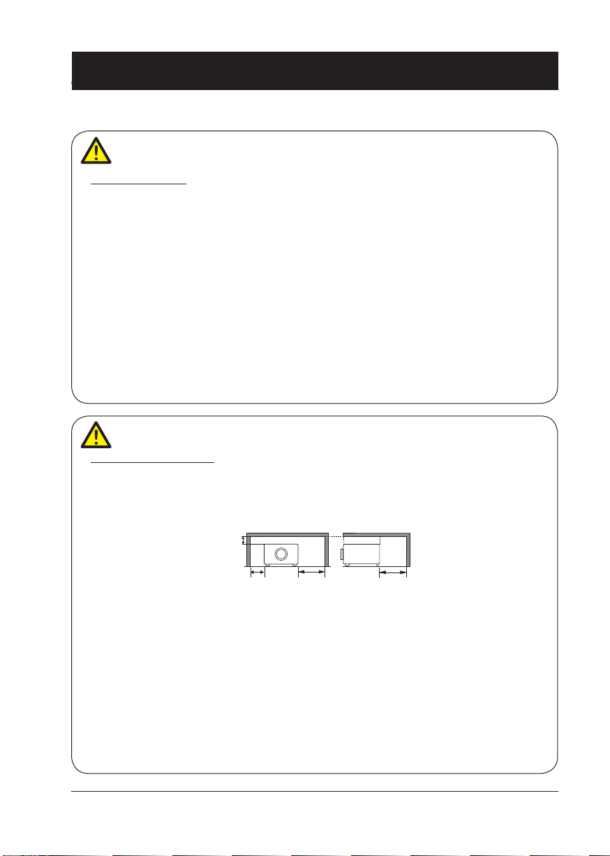
0.7’(20cm)
3’(1m)
3’(1m)
1.5’(50cm)
Notes
Caution
Safety precautions:
●GROUND the projector.
●Lens of the projector projects strong light. DO NOT look at the light beam directly. You may
get the eyesight hurt. This is especially the case with children.
●Unplug the AC power plug if the projector will not be used for long time.
●DO NOT overload the socket of power cord as it may lead to re or electric shock. DO
NOT subject the power cord to any object. DO NOT place the projector in locations
where its power cord may become damaged by treading by passersby.
●Disconnect the power plug before cleaning the projector. DO NOT apply liquid or sprays
to the projector. DO NOT wipe the projector with wet cloth.
●Please follow warnings and instructions given in labels attached to the projector. Unplug the
projector when the projector is exposed to thunderstorm weather, is unmanned, or
not in use for long periods to prevent damage caused by lightning and power surges.
●DO NOT use accessories without recommendation by the manufacturer as it may result in
potential risks.
Caution
Precautions on air outlet:
●Keep adequate clearance around the projector for its ventilation and cooling. See gure be-
low for the least clearance requirements. The least clearance is a MUST when the projector
is placed within a cabinet or other closed environment.
Sides and bottom Rear
●DO NOT cover the air outlet of the projector. Poor ventilation not only shorten life cycle of
the projector but also may lead to risks.
●Slots and openings at rear and bottom of the projector are designed for ventilation. Keep the
projector from overheated to ensure its steady operation.
●DO NOT cover the air outlet with cloth or other objects. DO NOT place the projector on the
surface of bed, sofa, carpets, or similar object as this may block the air outlets at its bottom.
●DO NOT place the projector in closed environment, e.g. a bookcase, unless it is well venti-
lated.
● Keep any matter from falling in the projector through the air outlets as they may touch high
voltage parts and lead to re or electric shock by short circuits. DO NOT splash liquid to the
projector.
5
Page 6
Safety operation guideline
Note:
Precautions on location of the projector:
●Place the projector in a proper location or it may result in re.
●DO NOT expose the projector in rain or high humidity environments or it may result in re or
electric shock. DO NOT place the projector near water or splashing water. DO NOT place any
water container, e.g. ower vase, atop the projector.
●DO NOT place the projector in environments of soot, moisture or smoke, e.g. the kitchen, or
it may lead to product failure or accidents. The projector may be damaged by contact with oil
or chemicals.
●DO NOT place the projector near exhaust pipe or air conditioning equipment.
●DO NOT place the projector near radiator or heating pipes.
●DO NOT place the projector atop unstable truck, rack, or table. It may fall of the surface and
lead to personal injuries and property damages. Please use cart or rack recommended by the
manufacturer or included with the product. Please follow steps given in installation guideline
included with the wall and ceiling mount racks for installation. Use installation components
approved by the manufacturer.
●Be careful when moving the projector with cart. Abrupt stops, pushing too hard and rugged
surfaces may topple the projector and the cart together.
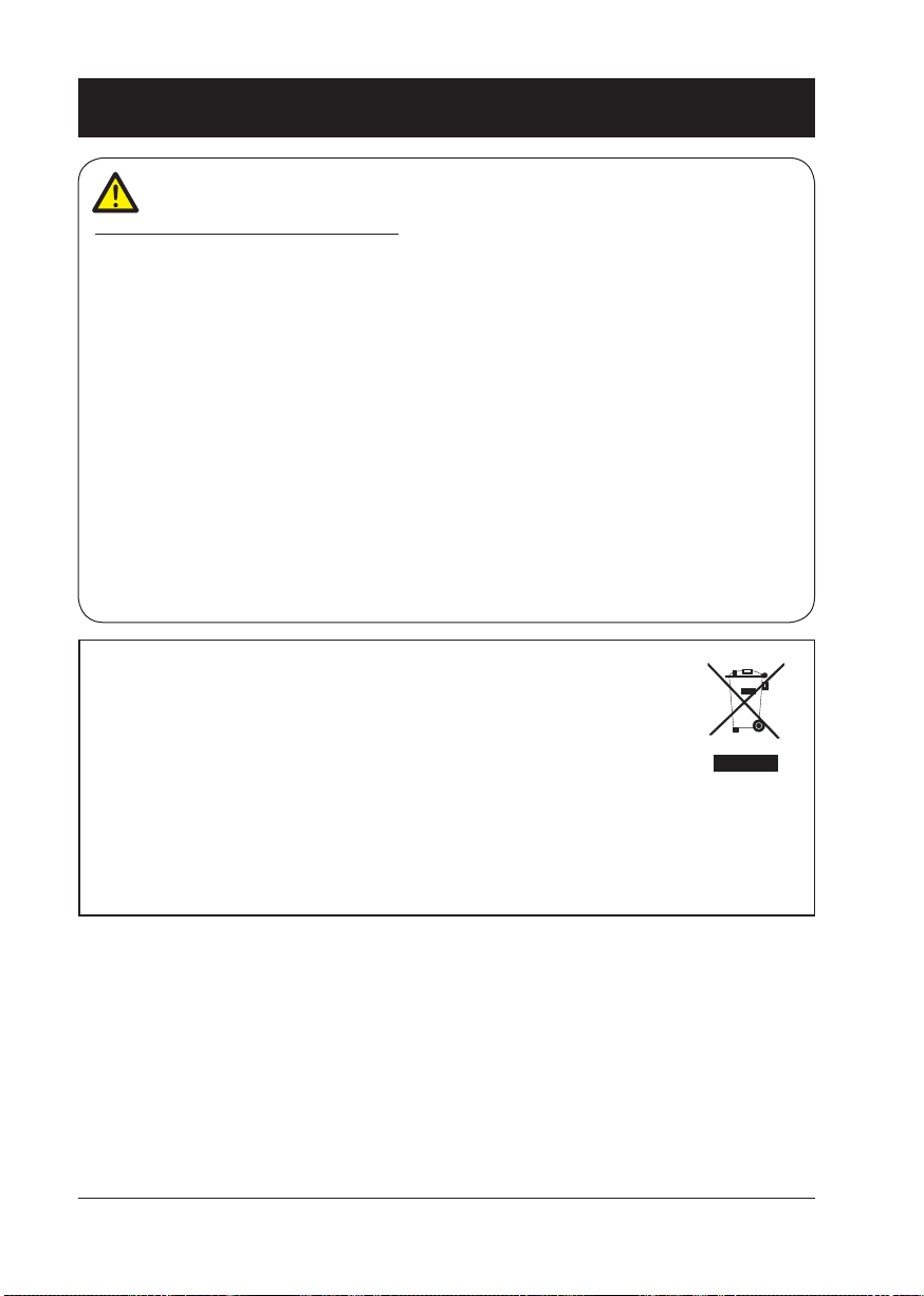
FOR EU USERS
The symbol mark and recycling systems described below apply to EU countries and
do not apply to countries in other areas of the world.
The product is designed and manufactured with high quality materials and
components which can be recycled and/or reused.
The symbol mark means that electrical and electronic equipment, batteries and accumulators, at their end-of-life, should be disposed of separately from the household waste.
Note:
If a chemical symbol is printed beneath the symbol mark, this chemical symbol means
that the battery or accumulator contains a heavy metal at a certain concentration.
This will be indicated as follows: Hg: mercury, Cd: cadmium, Pb: lead In the European
Union there are separate collection systems for used electrical and electronic equipment,
batteries and accumulators.
Please, dispose of them correctly at the local community waste collection/recycling centre.
Please help us to conserve the environment we live in!
6
Page 7
Safety operation guideline
Note:
Precautions on using the projector:
●DO NOT project the same image for long time as residual images may be left in the panel.
This is a property of LCD panel.
●Use power as indicated in tags attached to the projector. If you have doubts over available
power type, consult the dealer or local power company rst.
●DO NOT open or remove the casing for maintenance as this may lead to electric shock or
other damages. Call qualied maintenance personnel in case of any maintenance require-
ments.
– In case of the following, unplug the power cord and call qualied maintenance personnel
for service immediately:
a. Damaged or broken power cord or plug
b. Liquid splashed in the projector
c. The projector exposed to rain or water
d. If the projector fails to work as expected by following operation instructions, adjust it ac-
cording to given instructions. Other invalid operations may damage the projector, which
requires the technician to spend more time before returning it back to normal.
e. The projector falls off to ground or its casing is damaged.
f. In case of any abnormal change in the projector during its use, then maintenance services
would be required.
●In case components replacement is required, make sure the replacements have been ap-
proved by the manufacturer and features the same with the one being replaced. Use of
unauthorized parts may lead to re, electric shock or personal injury.
●After the completion of maintenance or repair work, get the maintenance personnel to run
routine safety check to ensure the projector’s safety operation status.
Information for users in the European Union
This is a device to project images onto a screen, etc., and is not intended for use as indoor lighting in a
domestic environment. Directive 2009/125/EC.
7
Page 8
Safety operation guideline
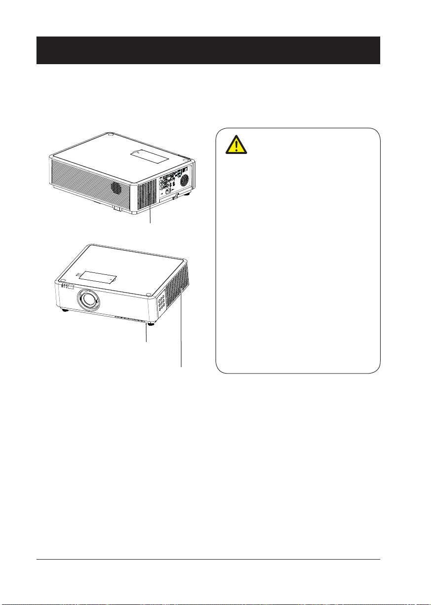
Air ventilation
Openings in the casing are designed for ventilation and overheating prevention. DO NOT block or
cover these openings to keep the projector in normal operation and from overheating.
Note:
Heat exhaust at the air outlet. Keep the
following in mind when using or installing
the projector:
– DO NOT place ammable materials or
sprayers near the projector.
– Keep the air outlet one meter away
Air intake
Air intake
from other objects.
– DO NOT touch the area close to the air
outlet especially the metal components,
e.g. screws. This area and parts will get
very hot once the projector starts operating.
– DO NOT place any object atop the pro-
jector. They may not only be damaged
but also lead to re after being over-
heated.
Cooling fans are designed for cooling
the projector. Fan speed is auto adjusted
subject to internal temperature of the
projector.
(For heat exhaust)
8
Air outlet
Page 9
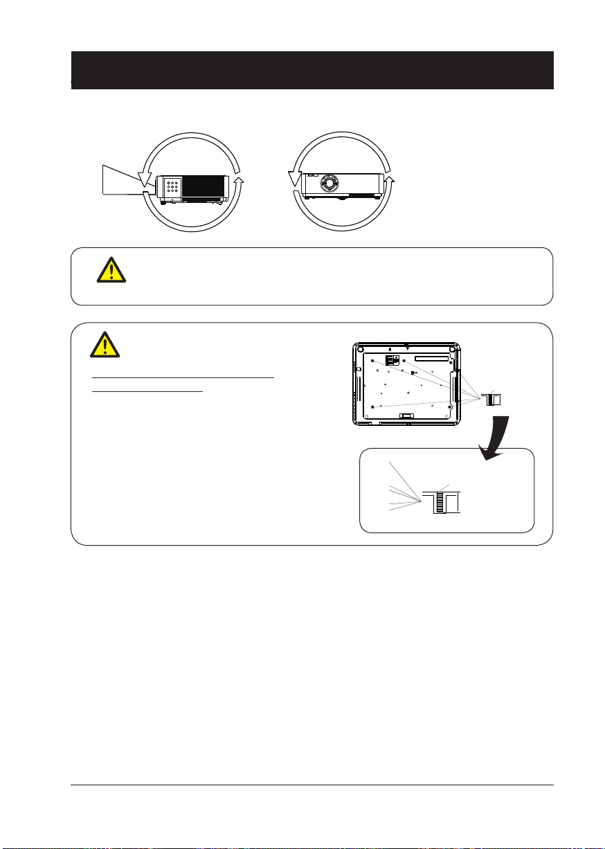
Safety operation guideline
360°
The projector supports 360° projection vertically and horizontally.
360°
Note:
Enable the “Ceiling” function if ip over screen is required.
•
Note:
Precautions on ceiling mount
racket installation:
●Get qualied technician to install the ceil-
ing mount racket.
●Warranty of the projector does not cover
hazards and damage caused by using
ceiling mount rackets provided by unauthorized dealers.
●Remove the ceiling mount racket when it
is not in use.
●Apply torque driver instead of power driv-
er or impact driver in the projector.
360°
M4x10
10mm
M4x10
10mm
9
Page 10
Safety operation guideline
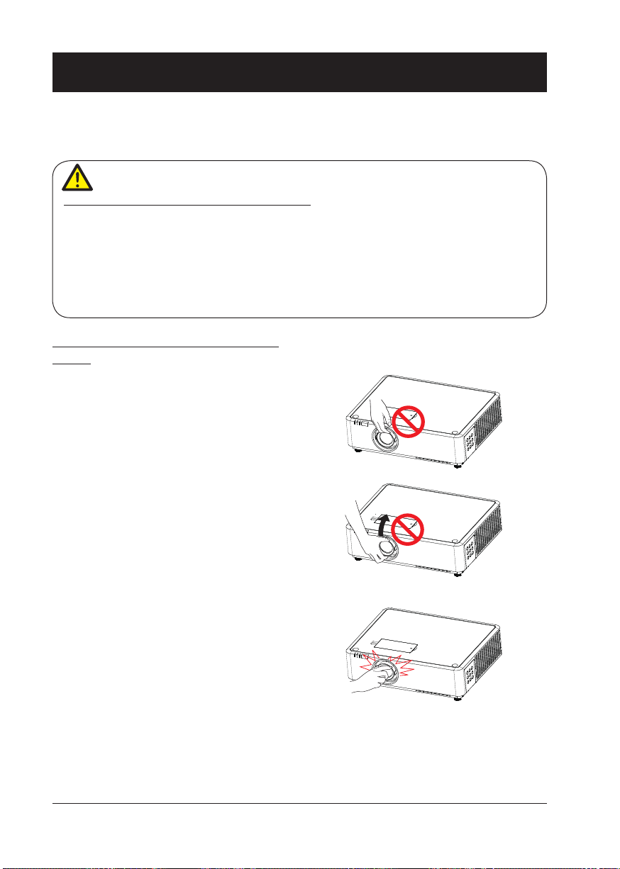
Moving the projector
When moving the projector close its adjustment legs as they may damage the lens and casing.
Keep the projector in suitable box when it is not to be used for a long time.
Note:
Precautions on moving or shipping the projector:
●DO NOT drop or impact the projector as it may get damaged or failed in operation.
●Please employ proper container for movement.
●Prohibit express or other shipping service provider personnel from shipping the projector
with improper boxes. The projector may become damaged. Please consult the dealers for
shipping the projector by express or other shipping service providers.
●Place the projector in box only after it has been fully cooled down.
Precautions on dealing with the projector:
DO NOT lift or move the projector by holding
the lens or projecting decoration ring as it
may damage the lens and the projector.
Be careful when handling the projector. DO
NOT drop it, subject it to external forces, or
place objects atop it.
10
DO NOT hold the lens or area around it.
Page 11
Compliance
ASA
FCC Caution
Declaration of Conformity
This device complies with Part 15 of the FCC Rules.
Operation is subject to the following two conditions:
(1) This device may not cause harmful interference, and (2) this device must accept any interference
received, including interference that may cause undesired operation.
To assure continued compliance, follow the attached installation instructions and do not make any
unauthorized modications.
CAUTION:
This equipment has been tested and found to comply with the limits for a Class A digital device, pursuant
to part 15 of the FCC Rules. These limits are designed to provide reasonable protection against harmful
interference when the equipment is operated in a commercial environment. This equipment generates,
uses, and can radiate radio frequency energy and, if not installed and used in accordance with the
instruction manual, may cause harmful interference to radio communications. Operation of this equipment
in a residential area is likely to cause harmful interference in which case the user will be required to
correct the interference at his own expense.
Model Number : EK-355U
Trade Name : EIKI
Responsible party : EIKI International, Inc.
Address : 30251 Esperanza Rancho Santa Margarita CA 92688-2132
Telephone No. : 800-242-3454 (949-457-0200)
AC Power Cord Requirement
The AC Power Cord supplied with this projector meets the requirement for use in the country you purchased it.
AC Power Cord for the United States and Canada:
AC Power Cord used in the United States and Canada is listed by the Underwriters Laboratories (UL)
and certied by the Canadian Standard Association (CSA).
AC Power Cord has a grounding-type AC line plug. This is a safety feature to be sure that the plug will
t into the power outlet. Do not try to defeat this safety feature. Should you be unable to insert the plug
into the outlet, contact the electrician.
AC Power Cord for the United Kingdom:
This cord is already tted with a moulded plug incorporating a fuse, the value of which is indicated on
the pin face of the plug. Should the fuse need to be replaced, an ASTA approved BS 1362 fuse must
be used of the same rating, marked thus
the cover omitted. If a replacement fuse cover is required, ensure it is of the same colour as that visible
on the pin face of the plug (i.e. red or orange). Fuse covers are available from the Parts Department
indicated in the User Instructions.
If the plug supplied is not suitable for the socket outlet, it should be cut off and destroyed.
The end of the exible cord should be suitably prepared and the correct plug tted.
WARNING : A PLUG WITH BARED FLEXIBLE CORD IS HAZARDOUS IF ENGAGED IN A LIVE
SOCKET OUTLET.
The Wires in this mains lead are coloured in accordance with the following code:
Green-and-yellow ...... . Earth
Blue . . . . . . . . . . . . . . . . Neutral
Brown............... Live
As the colours of the wires in the mains lead of this apparatus may not correspond with the coloured
markings identifying the terminals in the plug proceed as follows:
The wire which is coloured green-and-yellow must be connected to the terminal in the plug which is
marked by the letter E or by the safety earth symbol
The wire which is coloured blue must be connected to the terminal which is marked with the letter N
or coloured black.
The wire which is coloured brown must be connected to the terminal which is marked with the letter L
or coloured red.
WARNING: THIS APPARATUS MUST BE EARTHED.
. If the fuse cover is detachable, never use the plug with
or coloured green or green-and-yellow.
THE SOCKET-OUTLET SHOULD BE INSTALLED NEAR THE EQUIPMENT AND EASILY ACCESSIBLE.
11
Page 12
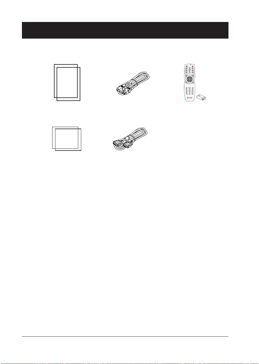
Accessories
Quick Start Guide AC Power Cord
US type x 1
Euro type x 1
Safety Information VGA Cable
Remote Control with batteries
(AA or LR6)
12
Page 13

Overview
This chapter presents names and
functions of individual component.
Page 14
Name and function of the projector
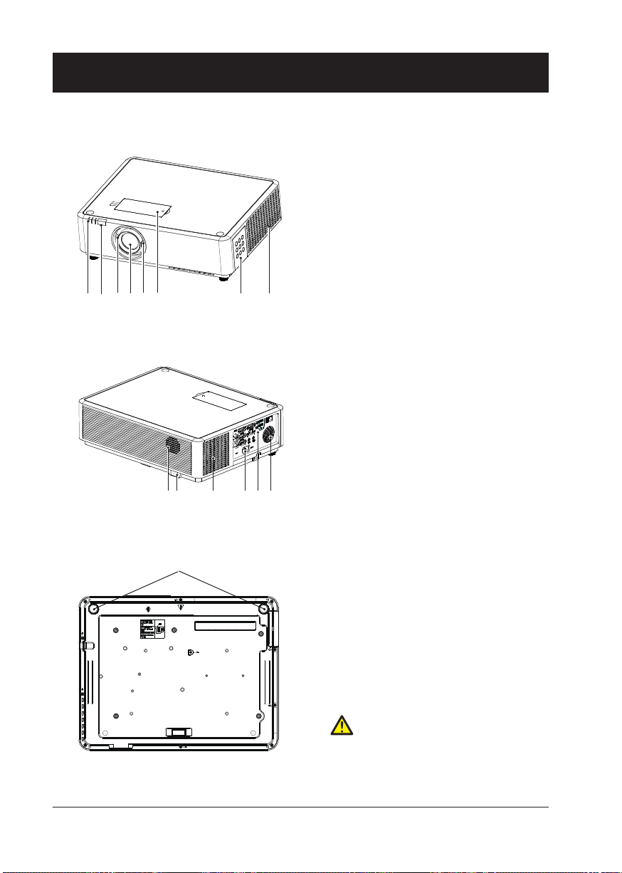
Front/top
① ② ③④ ⑤ ⑥ ⑦ ⑧
Rear
①
LED indicator (Power / Status / Filter)
②
Remote controller receiver (front)
③
Focus ring
④
Projection lens
⑤
Zoom ring
⑥
Cover of lens shift ring
⑦ Control panel
⑧ Exhaust vent
Speaker
⑨
⑩ Remote controller receiver (rear)
⑪ Intake vent
⑫ AC power cord connector
⑬ Input / Output terminal
⑭ Speaker
Bottom
14
⑨⑩ ⑪
⑮
⑫ ⑬⑭
⑮ Adjustable foot
Note:
Air exhaust emits hot air. DO NOT place
heat sensitive objects near it.
Page 15
Name and function of the projector
Model
Parts
Provider
Date
EK-350 series
Silk Prinng / Logo
Eliza Huang
2017.09.18
138.0
39.8
157.6
161.0
Model
Parts
Provider
Date
EK-350 series
Silk Prinng / Logo
Eliza Huang
2017.09.18
CAUTION HIGH TEMPERATURE
注意高温!
PRECAUCION CALIENTE
APPARECCHIO CALDO
ATTENTION CHAUD
WARNUNG HEISS
고온주의
138.0
39.8
157.6
161.0
138.0
39.8
157.6
161.0
Model
Parts
Provider
Date
EK-350 series
Silk Prinng / Logo
Eliza Huang
2017.09.18
CAUTION HIGH TEMPERATURE
注意高温!
PRECAUCION CALIENTE
APPARECCHIO CALDO
ATTENTION CHAUD
WARNUNG HEISS
고온주의
138.0
39.8
157.6
161.0
Model
Parts
Provider
Date
EK-350 series
Silk Prinng / Logo
Eliza Huang
2017.09.18
CAUTION HIGH TEMPERATURE
注意高温!
PRECAUCION CALIENTE
APPARECCHIO CALDO
ATTENTION CHAUD
WARNUNG HEISS
고온주의
138.0
39.8
157.6
161.0
Model
Parts
Provider
Date
EK-350 series
Silk Prinng / Logo
Eliza Huang
2017.09.18
CAUTION HIGH TEMPERATURE
注意高温!
PRECAUCION CALIENTE
APPARECCHIO CALDO
ATTENTION CHAUD
WARNUNG HEISS
고온주의
138.0
39.8
157.6
161.0
Model
Parts
Provider
Date
EK-350 series
Silk Prinng / Logo
Eliza Huang
2017.09.18
CAUTION HIGH TEMPERATURE
注意高温!
PRECAUCION CALIENTE
APPARECCHIO CALDO
ATTENTION CHAUD
WARNUNG HEISS
고온주의
138.0
39.8
157.6
161.0
Model
Parts
Provider
Date
EK-350 series
Silk Prinng / Logo
Eliza Huang
2017.09.18
CAUTION HIGH TEMPERATURE
注意高温!
PRECAUCION CALIENTE
APPARECCHIO CALDO
ATTENTION CHAUD
WARNUNG HEISS
고온주의
138.0
39.8
157.6
161.0
Model
Parts
Provider
Date
EK-350 series
Silk Prinng / Logo
Eliza Huang
2017.09.18
CAUTION HIGH TEMPERATURE
注意高温!
PRECAUCION CALIENTE
APPARECCHIO CALDO
ATTENTION CHAUD
WARNUNG HEISS
고온주의
138.0
39.8
157.6
161.0
Model
Parts
Provider
Date
EK-350 series
Silk Prinng / Logo
Eliza Huang
2017.09.18
CAUTION HIGH TEMPERATURE
注意高温!
PRECAUCION CALIENTE
APPARECCHIO CALDO
ATTENTION CHAUD
WARNUNG HEISS
고온주의
138.0
39.8
157.6
161.0
Model
Parts
Provider
Date
EK-350 series
Silk Prinng / Logo
Eliza Huang
2017.09.18
CAUTION HIGH TEMPERATURE
注意高温!
PRECAUCION CALIENTE
APPARECCHIO CALDO
ATTENTION CHAUD
WARNUNG HEISS
고온주의
138.0
39.8
157.6
161.0
Model
Parts
Provider
Date
EK-350 series
Silk Prinng / Logo
Eliza Huang
2017.09.18
CAUTION HIGH TEMPERATURE
注意高温!
PRECAUCION CALIENTE
APPARECCHIO CALDO
ATTENTION CHAUD
WARNUNG HEISS
고온주의
138.0
39.8
157.6
161.0
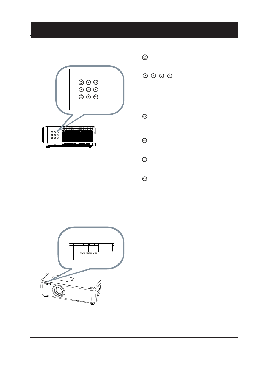
Control Panel
•
Power / Stand-by
Power on or off the projector
•
– Select items or adjust values in the
– Select display area in digital zoom+
Left / Right / Up / Down
OSD menu.
mode
– Adjust the volume.
OK
•
Enter the OSD menu or select options in
•
a menu
Input
PRECAUCION CALIENTE
APPARECCHIO CALDO
ATTENTION CHAUD
WARNUNG HEISS
고온주의
CAUTION HIGH TEMPERATURE
注意高温!
Select source of input
LED indicator
•
Menu
Open or close the OSD menu
•
Auto
Optimize a computer image automatically
• POWER indicator
– The power indicator turns steady red
when the projector is in standby mode
– It turns steady green when the projector
is in normal operation
• STATUS indicator
It ashes orange when internal temperature of the projector is out of operation
range
• FILTER indicator
It turns orange when the lter requires
cleaning
15
Page 16
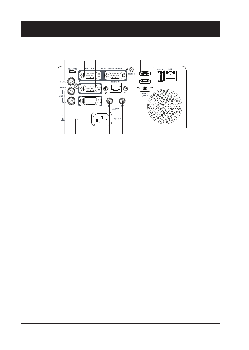
Terminal
Name and function of the projector
①
② ③ ④ ⑤ ⑥ ⑦ ⑧ ⑨ ⑩
⑪ ⑫ ⑬ ⑭ ⑮ ⑯ ⑰
① VIDEO IN
Connect video output signal to this terminal.
②
Micro-USB
The terminal is to use the USB display function,
when connected the projector to computer with
USB cable
VGA IN 1
③
Connect output signal from computer to this
terminal.
VGA OUT
④
Transmit signals from ③ or ⑤ to other displays
when the projector is acting as a output display.
VGA IN 2 / YPbPr / S-VIDEO
⑤
Connect output signal from computer, YPbPr or
S-Video to this terminal.
HDBaseT
⑥
Connect to this terminal through a network cable
to achieve the HDBaseT function.
HDMI 1
⑦
Connect HDMI digital output signals to this
terminal.
HDMI 2(MHL)
⑧
Connect HDMI digital output signals or MHL
digital output signals to this terminal.
⑨ USB
When using the Memory Viewer function, insert
the USB Flash Drivesy to this terminal directly.
LAN
⑩
Connect network cable to this port for controlling
and operating the projector via network.
AUDIO (L/R)
⑪
Connect audio signals to this terminal.
Kensington Security Slot
⑫
This slot is for a Kensington lock used to deter
theft of the projector.
* Kensington is a registered trademark of ACCO
Brands Corporation
RS232C
⑬
Connect serial cable to this terminal when using
RS232 device to control or operate the projector.
Power cord connector
⑭
⑮
AUDIO IN
Connect audio signals
⑯
AUDIO OUT
Output audio signals to amplier or other audio
equipment.
Speaker
⑰
16
Page 17
Name and function of the projector
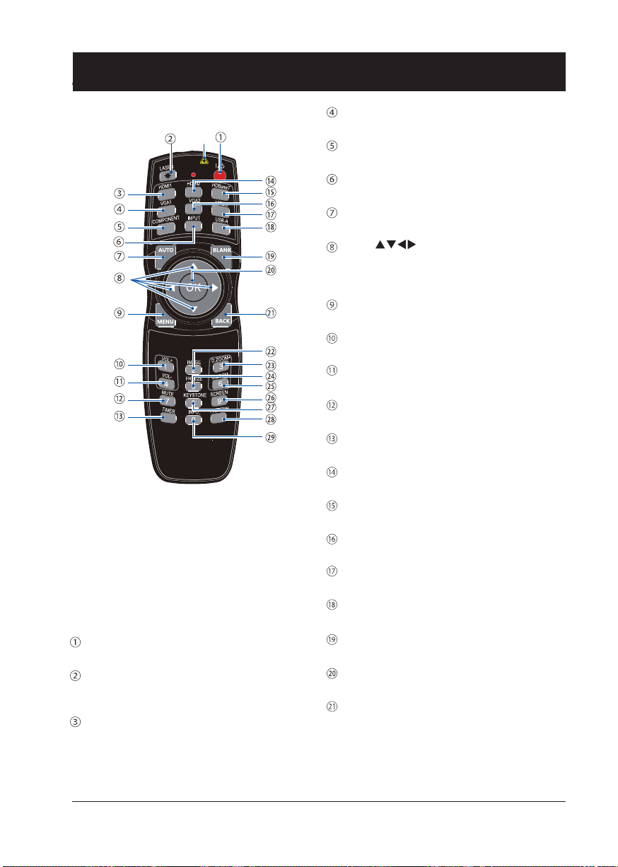
Remote controller
*
*
Laser Transmitting Window:
Laser beam will emit from this window while
pressing LASER button during the projection
to use the remote controller as a laser pointer.
Do not stare directly at the laser transmitting
window or aim the window at human body, to
avoid any physical injury.
POWER
Power on or off the projector.
LASER
Press the LASER button during presentation to
use the remote controller as laser pointer.
HDMI
Select HDMI input source.
VGA 1
Select VGA 1 input source.
COMPONENT
Select Component input source.
INPUT
Open or close the INPUT menu.
AUTO
Optimize a computer image automatically
Arrow
–Select items or adjust values in the OSD
menu
–Select display area in digital zoom+ mode.
MENU
Open or close the OSD menu.
VOLUME +
Increase volume.
VOLUME -
Decrease volume.
Mute
Mute the sound.
TIMER
Enable the timer function.
HDMI 2
Select HDMI 2(MHL) input source.
HDBaseT
Select HDBaseT input source.
VGA 2
Select VGA 2 input source.
VIDEO
Select VIDEO input source.
USB-A
Select Memory Viewer input source.
BLANK
Dark out screen images temporarily.
OK
Enter the OSD menu or select options in it.
BACK
Backward or exit the OSD menu.
17
Page 18
Name and function of the projector
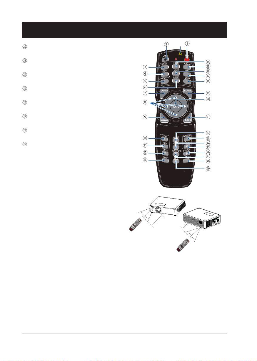
IMAGE
Select image mode.
D.ZOOM+
Zoom in projected image.
FREEZE
Freeze projected images.
D.ZOOM-
Zoom out projected image.
SCREEN
Select screen size.
KEYSTONE
Keystone calibration.
PATTERN
Select built-in test pattern of the projector.
INFO.
Display current status information of the
projector.
Operation range of remote controller
Point the remote controller to the IR receiver of
the projector
Maximum operation range of the remote controller is an area of radius 5 meters / arc 60° in
front of and behind the projector
TIMER
30°
VOL+
VOL-
IMAGE
MUTE
FREEZE
KEYSTONE
INFO.
SCREEN
PATTERN
*
LASER
HDMI1
VGA1
HDMI2
COMPONENT
VGA2
HDBaseT
INPUT
AUTO
VIDEO
USB-A
BLANK
MENU
30°
BACK
D.ZOOM+
D.ZOOM-
5m
5m
18
30°
LASER
HDMI1
VGA1
HDMI2
COMPONENT
VGA2
HDBaseT
INPUT
AUTO
VIDEO
USB-A
BLANK
MENU
VOL+
BACK
VOL-
IMAGE
MUTE
30°
FREEZE
TIMER
D.ZOOM+
KEYSTONE
D.ZOOM-
INFO.
SCREEN
PATTERN
Page 19
Name and function of the projector
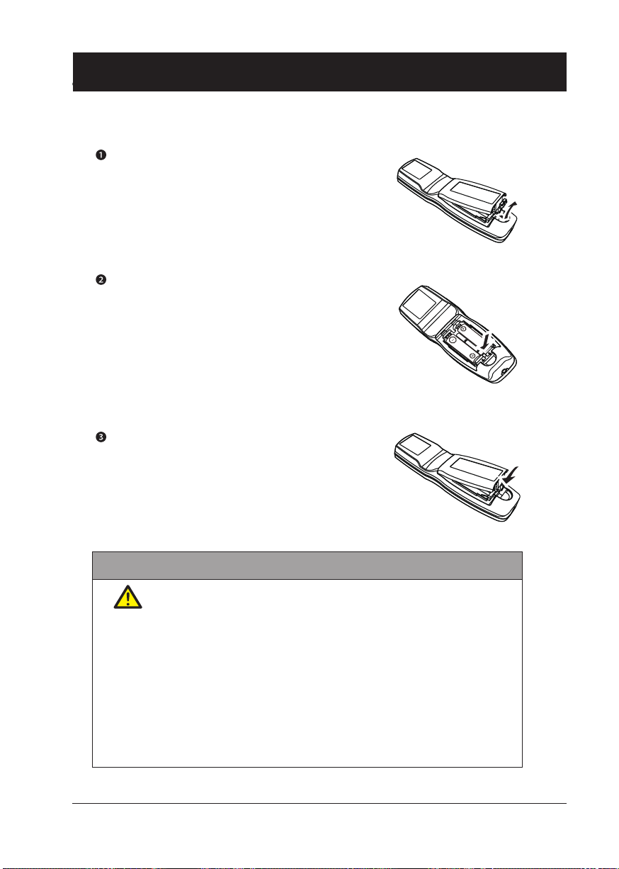
Install battery of remote controller
Open the battery cover.
Insert a new battery in it.
Two AA (LR6) batteries
Place the batteries with its anode
and cathode (+ and -) in correct
direction. Keep both poles in
good connection to the contacts
within the compartment.
Put the cover back.
Please follow the following rules for safety operation:
● Use two of AA or LR6 alkaline batteries.
● Replace both batteries at the same time.
● Do not mix new and old batteries as one pair.
● Keep the remote controller away from water or other liquids.
● Do not expose the remote controller to environments with high hu-
midity or temperature.
● Do not drop the remote controller.
● In case of any battery solution leaking in the compartment, clear it
thoroughly before placing new batteries in it.
● Using battery of other types than what specied on this manual may
lead to risks of explosion.
● Please dispose the old battery by following instructions given in tag
of the battery or local regulations.
19
Page 20

Installation
This chapter introduces the information
of install.
Page 21
Installation
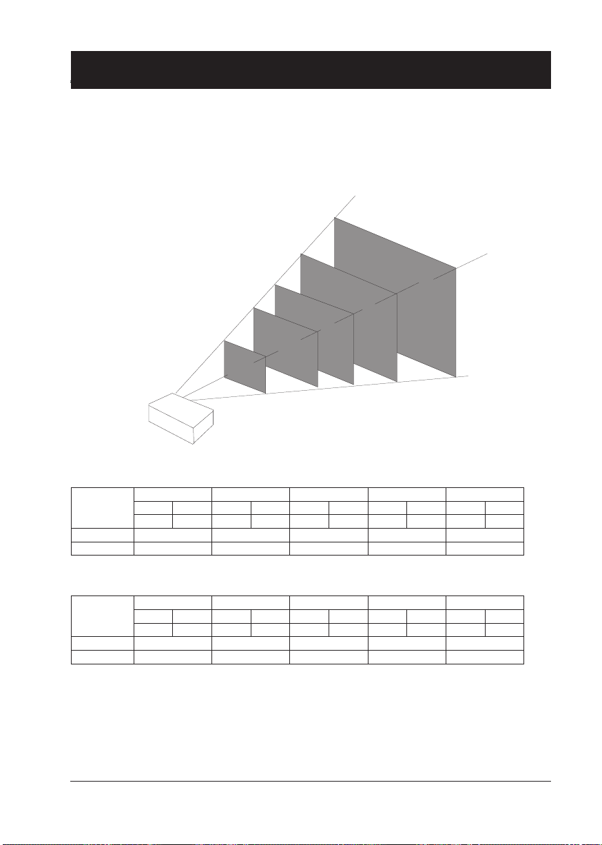
Set up the projector
● Ambient brightness may affect the projection image quality. For the optimal image effect, it is
recommended to control brightness in the environment.
● Values shown in gure below are approximates only. They may differ from the actual ones.
300"
200"
150"
100"
40"
EK-355U (16:10) Unit:cm
Screen size
Maximum 92.8 236.9 357.0 477.1 717.2
Minimum 152.3 384.9 578.8 772.7 1160.5
EK-355U (16:9) Unit:cm
Screen size
Maximum 95.5 243.6 367.0 490.4 737.3
Minimum 156.6 395.7 595.0 794.3 1192.8
40" 100" 150" 200" 300"
Width Height Width Height Width Height Width Height Width Height
86 54 215 134 323 202 431 269 646 404
40" 100" 150" 200" 300"
Width Height Width Height Width Height Width Height Width Height
89 60 221 125 332 187 443 249 664 374
21
Page 22
Installation
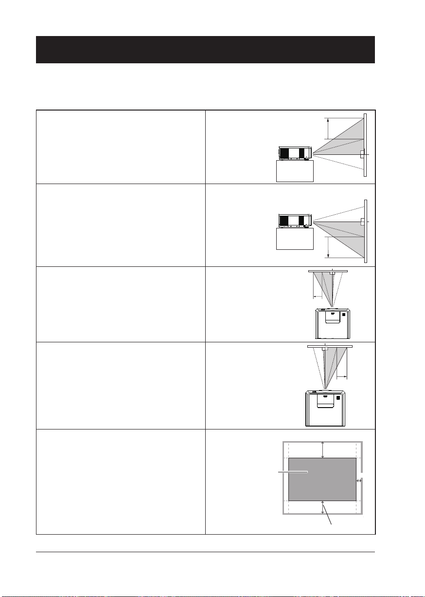
Lens shift adjustment
The electric lens shift function may adjust the lens in all four directions.
This function enables easy image position adjustment.
The projection location of the image may be
moved upward a distance up to 38% of the
length of the image.
The projection location of the image may be
moved downward a distance up to 27% of the
length of the image.
The projection location of the image may be
moved leftward a distance up to 7% of the
width of the image.
The projection location of the image may be
moved rightward a distance up to 7% of the
width of the image.
Move lens to
top position
Move lens to
bottom position
Move lens to
leftmost position
Move lens to
rightmost position
Center of the lens
Scope of lens shift adjustment
*When the setting of LENS SHIFT as the maximum position, the corner of projection image might be darker.
22
38%
7%
27%
Lens shift range
Page 23
Connection to equipment
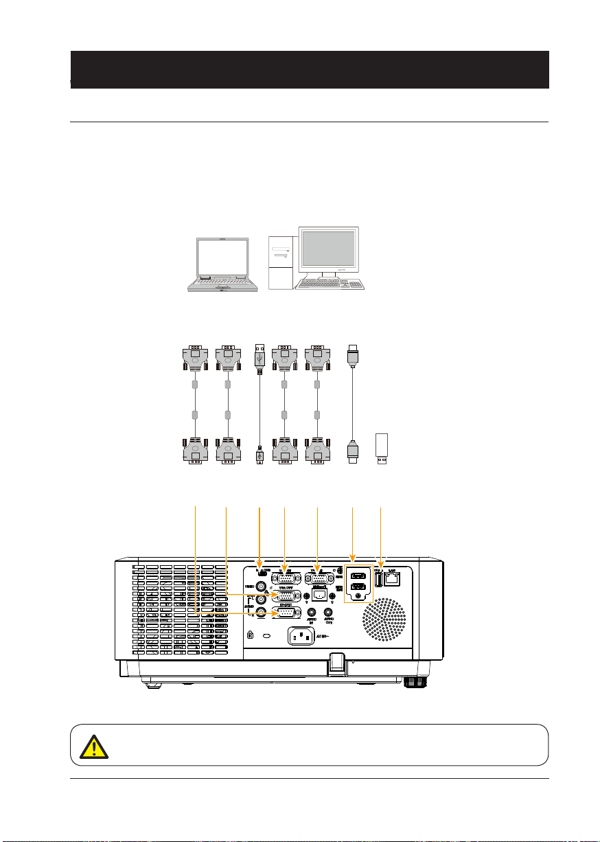
Connection to computer
Cables used for connection:
● VGA cable ● USB cable*
● HDMI cable* ● USB device*
● Serial cable*
(*Cables are not supplied with the projector)
RS232
output
Serial
cable
RS232
input
VGA
cable
output
VGA
input
VGA
USB-A
USB
cable
Micro-
output
VGA
cable
USB
input
VGA
output
VGA
input
VGA
cable
VGA
output
VGA
input
output
HDMI
cable
HDMI
HDMI
input
USB
device
USB-A
input
Unplug power cords of the projector and all external equipment before connecting
any cable to them.
23
Page 24
Connection to equipment
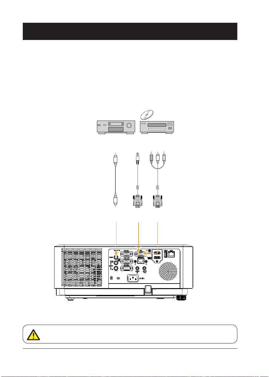
Connection to video equipment
Video
output
S-video
output
Component
output
Video
cable
Video
input
S-video
conversion
cable
S-video
input
Component
conversion cable
Component
input
Unplug power cords of the projector and all external equipment before connecting any
cable to them.
24
Page 25
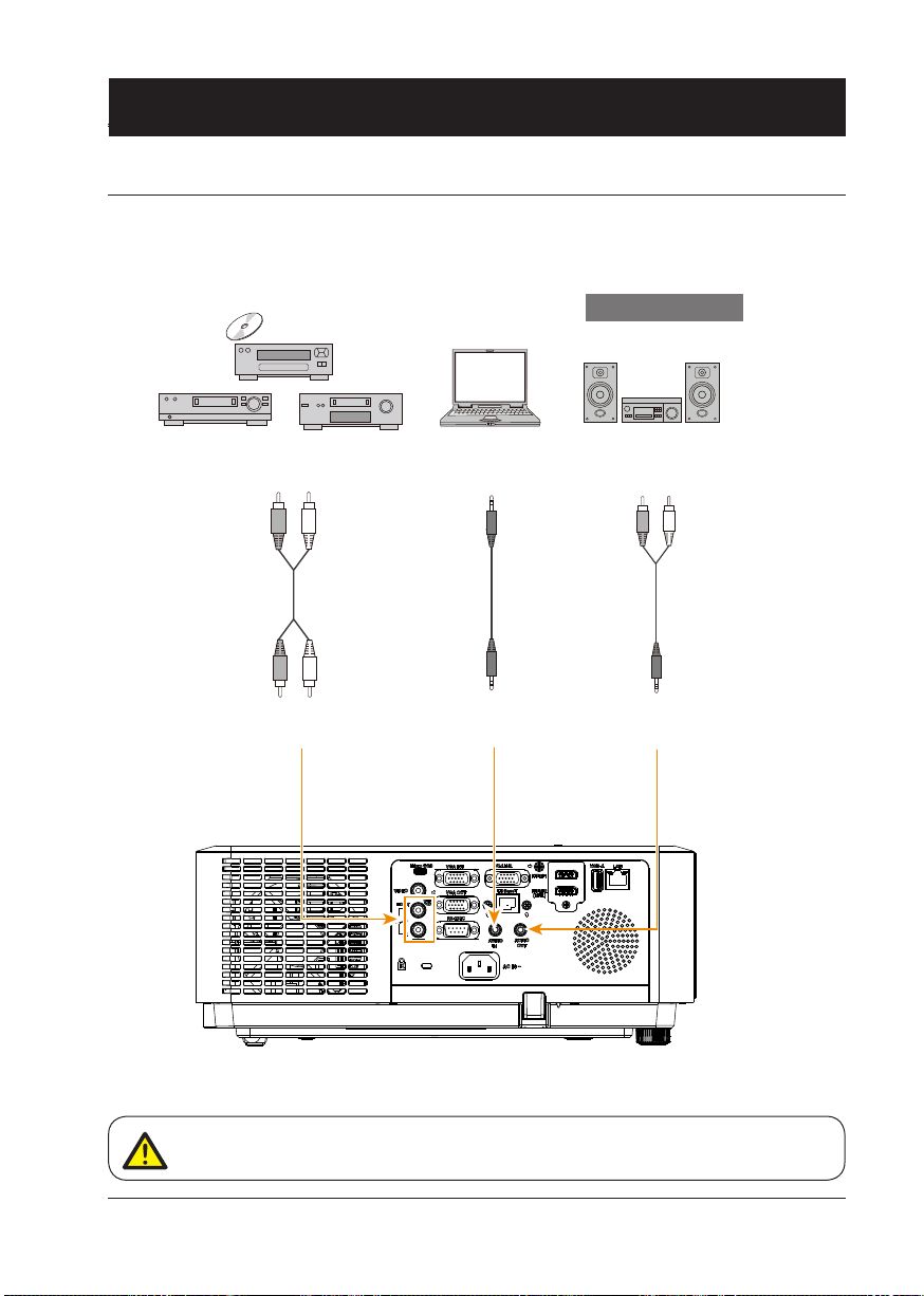
Connection to equipment
Connection to audio equipment
External audio equipment
Note: The left and right
channels are combined
when there is only the
L(mono) is inserted.
Audio output
(R) (L)
Audio
cable
(R) (L)
Audio input
Audio
output
Audio cable
(stereo)
Audio
input
Audio
input
Audio
output
Audio cable
(stereo)
Unplug power cords of the projector and all external equipment before connecting any
cable to them.
25
Page 26
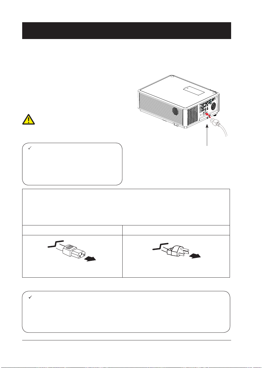
Connection to equipment
Connect the AC power cord
Standard voltage employed by the projector is AC 100-240V. It adapts to different input voltage
automatically. The projector employs 2-phase power cord with neutral ground cable.
Do not use any other type of power cords or you
may face the risks of electric shock. In case you
have any doubt on type of power cord you are
using, please call authorized dealer or service
center for help. Before powering on the projector,
get all external equipment connected in advance.
Note:
Keep the AC power socket close to the projector for easy plugging and unplugging.
Note:
For safety reasons, unplug the AC power
cord when the projector is not in use. The
projector will consume a small amount
of power when it is connected to AC grid
power and in standby mode.
Precautions on power cord
The AC power cord should meet regulations of the country/district where the projector is used.
Please make sure the type of the power plug is compliant with those given in gure below.
Make sure you are using a valid AC power cord.
In case the included AC power cord does not comply with the AC power socket in the location,
call the dealer for replacement.
The projector side Connect to the AC power socket
Connect to power cord connector of
the projector
Note:
● Use of invalid power cord may hamper product performance or even lead to electric
shock, re, and other incidents. Please use power cord compliant with the included one
to ensure product performance and operation safety.
● The frequently used cables are: AC power cord, VGA cable, audio cable, video cable,
and RS232 control cable.
Connect to AC power socket
Connect included
AC power cord to the
projector.
Grounding end
26
Page 27

Operation
This chapter introduces you to basic
operation of the projector.
Page 28

Basic operation
Power on the projector
Power
Power
1. Connect all external equipment to the projector (e.g. computer or media player)
before powering it on.
2. Connect AC power cord of the projector to an AC power socket.
The Power indicator turns on in red.
3. Press the Power button on the control panel or the remote controller.
The Power indicator lights in green and the cooling fan starts running.
4. If the projector is setting as password protected, the password dialog box displays.
Enter the password as instructed below.
Enter password (PIN)
Press ENTER button to start input the PIN code. Press
ENTER button to select and the cursor would move to next eld automatically. The number you typed
is displayed as “
reset.
After ll in the PIN code, the cursor would
move to the "Set" selection. Press the ENTER button and now you are ready to use the
projector. Or press
give up the setting.
If the password is invalid, the password displayed as “
with a valid one.
”. Repeat this step to ll in a 3-digit number. If any mistake, press MENU button to
button select "Cancel" to
” will be in red. Please try again
button to select a number, then press
Note:
● In case the “Logo Select” option is set
to OFF, then no welcome image will
display in screen.
● You can do nothing but powering
off the projector during the welcome
image is displaying.
28
What is a password (PIN)?
A password (PIN) is an ID code for identifying people with knowledge about it to
operate the projector. A password (PIN) setting may help preventing the projector from
unauthorized use.
You password (PIN) code is a 3-digit number. To find out more about protecting the
projector with a password (PIN), please refer to the PIN Code Lock function in the
Setup menu on Page 50 for details.
Precautions on password (PIN) operation
You cannot operate a password (PIN) protected projector without correct password
(PIN) Please set up a new password (PIN) and keep the operation manual in safe
place. In case the password (PIN) is lost or forgotten, call the dealer or service center.
Page 29

Basic operation
Power off the projector
1. Press the Power button at the control panel
or the remote controller, the “Power off?”
message displays.
2. Press the Power button again in 4 seconds
after the “Power off?” message prompted
to you. The POWER indicator ashes red
while the cooling fan continues running.
(You may set up noise level and speed of
the fan.) Unplug the power cord until the fan
stops running. Failure to do so may shorten
life cycle of the projector or lead to power
on failures or operation abnormalities.
3. The POWER indicator stops ashing once
the projector has been cooled down to
ready for power on again.
Do not use the projector without stop.
As it may hurt the life cycle of the
LED light source. Power off the projector at least once every 24 hours
and have it idle for an hour.
Power
Power
Power off?
“Power off?” message disappears
in 4 seconds.
Note:
● If the “On Start” function is set to “On”, the projector will power on once it is connected to an
AC power socket. (Refer to page 43)
● Speed of the cooling fan varies with internal temperature of the projector.
● Do not place the projector in any box before it is fully cooled down.
● In case the STATUS indicator flashes or turns red, refer to the “Light indicator status” for
instructions. (Refer to page 77)
● The POWER indicator flashes when the LED light source is cooling down. Do not power on
the projector at this time. Power on the projector only after the POWER indicator turns red.
● Unplug the power cord after the projector has been turned off. The fan stops running.
● The POWER indicator turns red when the projector is ready for power on again.
29
Page 30

Basic operation
Zoom / focus function
Rotate the ZOOM ring to zoom in or zoom out
the image.
Rotate the FOCUS ring to adjust the focus of
the image.
Lens Shift function
Perform the lens shift adjustment with ① and
.
②
Rotate①, the screen may deviate up-anddown from the central axis of lens shift up:38%
and down:27% elevation of the display.
Rotate②, the screen may deviate left-andright from the central axis of lens shift 7%
width of the display.
ZOOM ring
(outer)
①
FOCUS ring
(inner)
②
Adjustable pad
The projector can be adjusted up to 5º with the
adjustable pads.
Rotate the adjustable pad to lift the projector to
a certain height. During lifting, rotate the pad
clockwise.
To lower or retract the adjustable pads, rotate
the pad counterclockwise.
Keystone distortion of projected images can
be corrected by auto settings, remote control
operation or menu operation.
30
Adjustable pads
Page 31

Expend
Auto setup
Basic operation
H/V Keystone
Expend
Auto setup
Input search
Auto PC adj.
Auto keystone
Auto setup function
Press the AUTO button on the remote controller to auto execute settings given in the Auto
Setup menu (including Auto Searching, Auto
PC Adjusting and Auto Keystone).
Input search
Auto PC adj.
Auto keystone
Keystone adjustment
You may adjust keystone distortion of image in the projector with the keystone adjustment.
Follow steps below to adjust keystone distortion of projected image manually.
Press the KEYSTONE button on the remote controller.
The Keystone selection menu show up, press
to select the adjustment.
The keystone adjustment dialog box displays, press
button to adjust keystone distortion.
You may save the settings for keystone adjustment.
H/V Keystone
Adjust the projected image when the projector is on
the horizontal or vertical keystone distortion.
Corner correction
Adjust the projected image when the projector is
keystone distortion of four corners.
Reset value
The correction values will be restored to the factory
defaults.
button
Auto
Keystone
adjustment
Keystone adjustment
Corner correction
Reset value
Keystone adjustment
● The arrow mark looks white when there is no keystone adjustment in existence.
● The arrow mark indicating the adjustment direction turns red.
● The arrow mark disappears when the maximum adjustment limit reaches.
● The keystone adjustment will be canceled if you press the keystone adjustment button when it is
displaying.
● The adjustable range is subject to source of signal input.
31
Page 32

02
02
Basic operation
Remote controller operation
Use the remote controller for common operations.
Blank (BLANK)
Press the BLANK button on remote controller
a blank screen displays to replace existing
image. Press the BLANK button or any other
button to restore the image.
Press the BLANK to toggle switch the screen
as shown below:
BLANK → Normal → BLANK → Normal → ......
Image mode selection (IMAGE)
Press the IMAGE button on remote controller
to select required image mode.
Digital Zoom (D.ZOOM+/-)
Press the D.ZOOM+/- button on remote con-
troller to enter the Digital Zoom mode.
Screen size selection (SCREEN)
Press the SCREEN button on remote controller
to select required screen size mode.
Freeze (FREEZE)
Press the FREEZE button on remote controller
to freeze image on the screen and mute the
sound. Press the FREEZE button to cancel the
freeze function.
VOL
+/-
MUTE
TIMER
BLANK
IMAGE
D.ZOOM
+/-
SCREEN
Freeze
Volume +/- (VOL +/-)
Increase or decrease volume.
Mute the sound (MUTE)
Press MUTE button on the remote control to
turn off the volume. Press MUTE button again or
VOL+/- button to cancel mute function.
Timer (TIMER)
Press the TIMER button on remote controller.
A timer animation (00:00) displays and starts
timing in format of (00:00-59:59).
Press the TIMER button again to stop timing.
Press the TIMER button again to disable the
timing function.
:
Timer display
32
Blank Image
Blank
The Blank screen disappears if no
buttons are pressed in 4 seconds.
Page 33

Input selection
Input select
Direct operation
Press HDMI 1, HDMI 2, VGA 1, VGA 2, VIDEO,
HDBase T, COMPONENT or USB-A on the
remote control as input source.
Menu operation
1 Press INPUT button on the remote control or
control panel to display the input select menu.
2 Press button to select VGA 1, VGA
2, HDMI 1, HDMI 2(MHL), HDBaseT,
Component, Video, S-video, Memory Viewer,
Network or USB Display, then press the OK
button.
VGA 1
VGA 2
HDMI 1
HDMI 2(MHL)
HDBase T
Component
When input source is from computer
connected to VGA IN 1 terminal with
VGA cable, please select "VGA 1".
When input source is from computer connected to VGA IN 2(YPbPr/
S-VIDEO) terminal with VGA cable,
please select VGA 2.
When input source is from equipment connected to HDMI 1 terminal
with HDMI cable, please select
"HDMI 1".
When input source is from equipment connected to HDMI 2(MHL)
terminal with HDMI cable, please
select "HDMI 2".
When input source is from equipment connected to HDBaseT terminal with RJ45 cable, please select
"HDBaseT".
Select it when the input source is
from the video equipment connected
to VGA IN 2(YPbPr/S-VIDEO)
terminal via Component to VGA
cable.
Remote control
HDMI 2
VGA 2
HDMI 1
VGA 1
COMPONENT
Control Panel
Input select menu
HDBaseT
VIDEO
USB-A
INPUT
INPUT
VGA 1
VGA 2
HDMI 1
HDMI 2(MHL)
HDBase T
Component
Video
S-video
Memory Viewer
Network
USB Display
Video
Note:
Select it when the video input signal
is connected to VIDEO IN terminal.
- When the "Input search" function is set to "On" in the "Auto setup" function, the input signal will
be searched automatically.
33
Page 34

Input selection
S-video
Memory Viewer
Network
USB Display
Select it when the video input signal
is connected to VGA IN 2(YPbPr/
S-VIDEO) terminal via S-Video to
VGA adaptor cable
When input source is from device
connected to USB-A terminal, please
select "Memory Viewer".
When input source is from network
connected to LAN terminal with LAN
cable, please select "Network".
When input source is from the device
connected to Micro-USB terminal,
please select "USB Display".
Remote control
HDMI 2
VGA 2
HDMI 1
VGA 1
COMPONENT
Control Panel
Input select menu
VGA 1
VGA 2
HDMI 1
HDMI 2(MHL)
HDBase T
Component
Video
S-video
Memory Viewer
Network
USB Display
HDBaseT
VIDEO
USB-A
INPUT
INPUT
Note:
- When the "Input search" function is set to "On" in the "Auto setup" function, the input signal
except "USB Display", "Memory Viewer" and "Network" will be searched automatically.
- When signal is in "USB Display","Memory Viewer" and "Network", FREEZE, ASPECT, IMAGE,
AUTO SETUP, TEST PATTERN and SCREEN function cannot work.
34
Page 35

Basic operation
How to use the OSD
Main menu
Display
Auto PC adj.
Fine sync
H Position
V Position
H. Size
Aspect
Project way
Menu position
Background display
System
Menu operation
1. Press the MENU button on the rear control
panel or remote controller and the OSD
displays.
2. Press
main menu item. Press button or OK
button to enter a submenu.
3. Press
menu, then press OK button or button to
set up or enter an option.
4. Press
navigate options, then press OK button to
act on the item and exit.
5. Press button to return to mainmenu.
Press the MENU button on remote controller or control panel to exit the OSD.
button to act on or select one
button to select required sub-
button to select settings or
Sub menu
17
0
0
0
Normal
Front
Center
Blue
1024 x 768, 60Hz
OK
Menu
OK
Menu
35
Page 36

Menu item overview
Main menu
Basic operation
Sub menu
①
②
③
④
⑤
Display
Auto PC adj.
Fine sync
H Position
V Position
H. Size
Aspect
Project way
Menu position
Background display
System
17
0
0
0
Normal
Front
Center
Blue
1024 x 768, 60Hz
⑥
Display
Select Auto PC Adjust, Fine sync., H Position, V Position, H size, Aspect, Project way,
Menu position, Background display, System to align each parameter with the input signal format.
Color adjust
For computer input source, the color adjust options are: Image mode (Cinema/ Blackboard(Green)/ DICOM/ Colorboard/ User Image/ Dynamic/ Standard/ Bright), Contrast,
Brightness, Color temp., Red, Green, Blue and sharpness.
For the input source as video equipment, the color adjust options are: Image mode
(Cinema/ Blackboard(Green)/ DICOM/ Colorboard/ User Image/ Dynamic/ Standard/
Bright), Contrast, Brightness, Color, Tint, Red, Green, Blue and sharpness.
Setting
For computer input the setting options are: On start, Standby mode, High land, Light
source mode, Cooling fast, Closed caption, Key lock, Contrast optimization, Remote
control, Sound and HDMI setup.
For video input the setting options are: On start, Standby mode, High land, Light source
mode, Cooling fast, Closed caption, Key lock, Contrast optimization, Remote control
and Sound.
For HDMI input the setting options are: On start, Standby mode, High land,Light source
mode, Cooling fast, Key lock, Contrast optimization, Remote Control, Sound and HDMI
setup.
Expend
Setting the Language, Auto setup (Input search/ Auto PC adj./ Auto keystone), Keystone, Logo, Security, Power management, Filter counter, Test pattern, Network and
Factory default function as you need.
Memory Viewer
Setting the display method of Memory Viewer page as Set slide, Slide transition effect,
Sort order, Best t, Rotate, Repeat and Apply.
Information
Display information about the projector.
36
Page 37

OSD Setting-Display
Auto PC Adjusting
The Auto PC Adjusting function may get Total Dots, Horizontal and Vertical position, Display area H,
and Display area V aligned with computer input.
Direct Operation
Press Auto button on the remote control or control
panel to launch the Auto PC Adj. function.
Menu Operation
1 Press the MENU button on remote controller
and the OSD displays. Press
button to
select Display icon. Press button or OK
button and the Display menu displays.
2 Press
button to point to Auto PC Adj.
option, press OK button to conrm the choice.
Remote control
AUTO
Control Panel
Display menu
Display
Auto PC adj.
Fine sync
H Position
V Position
H. Size
Aspect
Project way
Menu position
Background display
System
AUTO
17
0
0
0
Normal
Front
Center
Blue
1024 x 768, 60Hz
Note:
- The projector executes the Auto PC adjustment automatically when the computer signals input the
projector for the rst time.
- Auto PC adjustment may not work depending on the model of the computer and the input signal.
- The Auto PC adjustment cannot be operated when 480i, 576i, 480p, 576p, 720p 1080i or 1080p is
selected in the "Display" menu → "System", or when the signal is coming from the HDMI terminal.
37
Page 38

OSD Setting-Display
Manual computer adjustment
The scan system of the projector may fail to detect signal format used by certain computers as
they opted some special signal format. The manual computer adjustment function of the projector
enables you to adjust individual parameter to align with most special signal format. The projector
comes with up to storage area to keep parameters manually adjusted by you. You may save preferred settings for certain computers as required.
1 Press MENU button on the remote controller or control panel and the OSD displays. Press
button to select Display icon, press button or OK button to conrm the selection.
2 Press button to select items for adjustment, press button or OK button to conrm the
selection. Press button to adjust settings.
Auto PC adj.
Adjust [Fine sync], [H Position], [V Position] and [H
Size] automatically.
Fine Sync
Eliminate ashes in image. Press button to
adjust Total Dots. (From 0 to 31)
H Position
Press button to adjust horizontal position of
image.
V Position
Press button to adjust vertical position of
image.
H size
Adjust and minimize the effect of interference
caused by projection of patterns consisting of
vertical stripes.
The projection of the vertical striped pattern may
cause cyclic patterns (noise). Adjust to minimize the
amount of interference.(From -15 to +15).
Note: H.Size must be set before adjust Fine sync.
Aspect
Press button to select the item to set the
screen size to t the image while maintaining the
aspect ratio of the input signal.
Normal ...... Projects the image at the maximum size
while maintaining the aspect ratio of the
input signal.
Wide ........ Projects the image at 16:9 aspect ratio.
Full ........... To provide an image to t the screen.
Advanced Splicing screen.
*Executing edge blending function
** Only effected with the VGA ans HDMI
signal
*** Edge blending software and its
manual can be downloaded from EIKI
website. See page 69 for usage of
Edge blending.
Note:
● The adjustment of Fine sync, H Position, V Position and H.Size is only for computer signal input.
● The Fine Sync, Total Dots and Clamp function will be disabled if 480i, 576i, 480p, 576p, 720p,
1080i or 1080p has been selected in the system menu.
38
Auto PC adj. Menu
Display
Auto PC adj.
Fine sync
H Position
V Position
H. Size
Aspect
Project way
Menu position
Background display
System
Note:
- The projector executes the Auto PC adjustment
automatically when the computer signals input the
projector for the rst time.
- Auto PC adjustment may not work depending on the
model of the computer and the input signal.
- The Auto PC adjustment cannot be operated when 480i,
576i, 480p, 576p, 720p 1080i or 1080p is selected in the
"Display" menu → "System", or when the signal is coming
from the HDMI terminal.
1024 x 768, 60Hz
Normal
Front
Center
Blue
17
0
0
0
Aspect menu
Display
Auto PC adj.
Fine sync
H Position
V Position
H. Size
Aspect
Project way
Menu position
Background display
System
1024 x 768, 60Hz
Normal
Front
Center
Blue
17
0
0
0
Page 39

OSD setting-Display
Project way
Press button to select the project way.
Front ........ Projects to front screen when projector is
front standing.
Rear ......... Projects to rear screen when projector is
front standing.
Ceiling/Front ..... Projects to front screen when
projector is in ceiling state.
Ceiling/Rear ..... Projects to rear screen when
projector is in ceiling state.
Auto Ceiling/Front: Projects to front screen when
projector is in ceiling state
automatically.
Auto Ceiling/Rear: Projects to rear screen when
projector is in ceiling state
automatically.
Menu position
Press button to select the position of the on
screen menu.
Upper left ....... Menu locates on upper left of the
screen.
Upper right ..... Menu locates on upper right of the
screen.
Center ......... Menu locates at the center of the
screen.
Lower left ....... Menu locates on lower left of the
screen.
Lower right ..... Menu locates on lower right of the
screen.
Background display
Press button to select the screen background of
the projector when there is no signal detected.
Black .... Select black background.
Blue ...... Select blue background.
Project way menu
Display
Auto PC adj.
Fine sync
H Position
V Position
H. Size
Aspect
Project way
Menu position
Background display
System
Menu position
Display
Auto PC adj.
Fine sync
H Position
V Position
H. Size
Aspect
Project way
Menu position
Background display
System
Background display
Display
Auto PC adj.
Fine sync
H Position
V Position
H. Size
Aspect
Project way
Menu position
Background display
System
Normal
Center
1024 x 768, 60Hz
Normal
Front
Center
Blue
1024 x 768, 60Hz
Normal
Front
Center
Blue
1024 x 768, 60Hz
Front
Blue
17
17
17
0
0
0
0
0
0
0
0
0
39
Page 40

OSD setting-Display
System
The projector automatically tunes to various types of computers with its function of Multi-scan system
and Auto PC Adjustment. If a computer is selected as a signal source, the projector automatically detects the signal format and tunes to project proper images without any additional setting.
One of the following messages may appear when input source as computer:
Auto
When the projector cannot recognize
the connected signal conforming to
the provided computer system, Auto
is displayed on the System menu
box and the Auto PC Adj. function
works to display proper images. If
the image is not projected properly,
a manual adjustment is required.
There is no signal input from computer.
----Check the connection between the
computer and projector.
When input source as VIDEO or S-Video
Auto
The projector may auto detect the input video
system and adjust to the optimum status. For
PAL-M or PAL-N video system, select the system manually.
PAL/SECAM/NTSC/NTSC4.43/PAL-M/
PAL-N
If image cannot be displayed correctly, you may
need to select one from PAL, SECAM, NTSC,
NTSC 4.43, PAL-M and PAL-N for playing.
System menu
Display
Auto PC adj.
Fine sync
H Position
V Position
H. Size
Aspect
Project way
Menu position
Background display
System
Normal
Center
1024 x 768, 60Hz
System for computer signal
Display
1024 x 768, 60Hz
----
----
----
----
----
System
VIDEO or S-Video system menu
Display
Auto
PAL
SECAM
NTSC
NTSC4.43
PAL-M
PAL-N
PAL-60
System
Front
Blue
17
0
0
0
Note:
● When HDMI, Component, HDBaseT, Network or USB display is selected, System menu for
computer is disable.
40
Page 41

OSD setting-Color Adjust (HDMI 1, HDMI 2, VGA 1, VGA 2, Memory Viewer, Network and USB Display signal)
Color Adjust
Menu operation
1 Press the MENU button on remote controller and the OSD displays. Press button select
Color Adjust icon, press button or OK button to conrm the selection.
2 Press button to point to required item and press OK button to conrm the selection.
Image mode
Switch image mode to t the image source and
the projector.
Dynamic
The light output is secondly maximized.
Standard
The picture becomes suitable for moving images
in general.
Bright
The light output is maximized.
Cinema
Enriched grayscale for viewing movies.
Chalkboard (Green)
An image mode designed for displaying on a
chalkboard (Green). It boosts quality of image
projected on chalkboard (Green).
DICOM
A highly clear X-ray image is reproduced. Digital radiographs with excellent detail and clarity for medical training, presentations and conferences.
Colorboard
Image mode suitable for image projecting on surface of wall in red, blue, yellow or green.
User Image
Default image mode set by users in the Image Adjust menu.
Contrast
Press button to decrease contrast, press button to increase contrast.
Brightness
Press button to decrease brightness, press button to increase brightness
Color Temp.
Press button to select required color temperature
High: Blueish image color
Mid.: Natural image color
Low: Reddish image color
Red
Press button to lighten red tint and button to darken it.
Green
Press button to lighten green tint and button to darken it.
Blue
Press button to lighten blue tint and button to darken it.
Sharpness
Press button to soften image and button to sharpen it.
Color adjust
Image mode
Contrast
Brightness
Color temp.
Red
Green
Blue
Sharpness
Standard
32
32
Mid
32
32
32
8
41
Page 42

OSD setting-Color Adjust (Video, Component and S-video signal)
Color Adjust
Menu operation
1 Press the MENU button on remote controller and the OSD displays. Press button select
Color Adjust icon , press button or OK button to conrm the selection.
2 Press button to point to required item and press OK button to conrm the selection.
Image mode
Switch image mode to t the image source and the
projector.
Dynamic
The light output is secondly maximized.
Standard
The picture becomes suitable for moving images in
general.
Bright
The light output is maximized.
Color adjust
Image mode
Contrast
Brightness
Color
Tint
Red
Green
Blue
Sharpness
Standard
Cinema
Enriched grayscale for viewing movies.
Chalkboard (Green)
An image mode designed for displaying on a chalkboard (Green). It boosts quality of image projected
on chalkboard (Green).
DICOM
A highly clear X-ray image is reproduced. Digital radiographs with excellent detail and clarity for medical training, presentations and conferences.
Colorboard
Image mode suitable for image projecting on surface of wall in red, blue, yellow or green.
User Image
Default image mode set by users in the Image Adjust menu.
Contrast
Press button to decrease contrast, press button to increase contrast.
Brightness
Press
button to decrease brightness, press button to increase brightness
Color
Press to decrease the chroma and
to increase it.
Tint
Press to select the appropriate tone for the image.
Red
Press
button to lighten red tint and button to darken it.
Green
Press
button to lighten green tint and button to darken it.
Blue
Press
button to lighten blue tint and button to darken it.
Sharpness
Press
button to soften image and button to sharpen it.
32
32
32
32
32
32
32
8
42
Page 43

OSD setting-Setting
Setting
On start
Standby mode
High land
Light Sourcecontrol
Cooling fast
Closed caption
Key lock
Contrast optimization
Remote control
Sound
HDMI Setup
Off
Eco
Off
Normal
Off
On
Setting
On start
Standby mode
High land
Light source control
Cooling fast
Closed caption
Key lock
Contrast optimization
Remote control
Sound
HDMI Setup
Off
Eco
Off
Normal
Off
On
Setting
The projector comes with convenient adjustment function.
1 Press the MENU button on remote controller and the OSD displays. Press
Setting icon, press button or OK button to conrm the selection.
2 Press button to point to required item and press OK button to conrm the selection.
On start
Setting the projector to be turned on automatically
just by connecting the AC power cord.
On .......... Start the projection with countdown
Off .......... Star t up in the standby mode.
Standby mode
Press button to select the item :
ECO
Normal
Network
х: No Control ∆: Power On command Only
√: All commands are active
*X: Power On command is active with “Wake On LAN” software.
Note:
● The “Wake On LAN” software and its manual can be downloaded from EIKI global website
https://global.eiki.com. File Name : Software_WakeOnLAN
High land
Control the fan speed through the Setting menu.
Off ...... Normal speed. Set it so if the projector is operated at normal altitude.
On ...... Faster speed than the setting as "Off". Set it so if the projector is operated at high altitude.
Note:
● Please change the setting as "ON", while operating the projector at an altitude around
1400~2700m.
Light source control
Change the brightness of the projection.
Cooling fast
provides the following options in the cooling
fans' operation after turning off the projector.
Normal(60 sec) .... As default cooling time.
30 sec .... Faster cooling time and louder
0 sec. ...... Allow to unplug the AC power cord
immediately.
LAN RS232C Keypad IR Control
х ∆ ∆ ∆
√ √ ∆ ∆
*х ∆ ∆ ∆
Normal .... Normal brightness.
Eco .......... Lower brightness, reducing
power consumption and
extending the life time of the light
source.
noise of fan.
immidiately without the cooling.
button to select
43
Page 44

OSD setting-Setting
Closed caption (Video signal only)
Allows the subtitle to be displayed for the audio
contents or other information. If the input source
contains closed caption, you can enable this
function and change the channel. Press to
select Off, CC1, CC2, CC3 or CC4.
Note:
● If the control panel accidentally becomes locked
and you do not have the remote control nearby or
there is something wrong with the remote control,
contact the dealer where you purchased the
projector or the service center.
● Closed caption is disable when screen menu or
Timer displayed on screen.
Keylock
Set the security for the projector operation.
O ff .......................... The control panel and remote controller are effective.
P rojector ................. Lock the operation of the control panel.
R emote Control ...... Lock the operation of the remote control.
Note:
● If you lock the top of the control panel, but
without a remote controller or something
wrong with the remote controller, please
contact the dealer or service center.
Contrast optimization
Select this function to optimize and compensate signal
automatically on the basis of the image, to get the best
contrast image.
On .... Increase the contrast of the image.
Off .... Disable this function.
Remote control
Prevent the interference from the remote controller
while multiple projectors or video devices are operated
at the same time. (default setting is Code 0)
Change code on Projector:
Code 0 ~ code 9 .... Select the specied ID number to
control the individual projectors.
Change code on remote controller:
Press and hold the OK button and one of the number
button for 5 seconds to set the code as the number
Light Indicator
you pressed. The code is set successfully when the
light indicator on the remote controller ashed.
Note: The projector and the remote controller
must be paired with the same code.
Setting
On start
Standby mode
High land
Light source control
Cooling fast
Closed caption
Key lock
Contrast optimization
Remote Control
Sound
HDMI Setup
Setting
On start
Standby mode
High land
Light source control
Cooling fast
Closed caption
Key lock
Contrast optimization
Remote control
Sound
HDMI Setup
Normal
Off
Eco
Off
Off
On
Eco
Normal
Off
Off
Off
On
44
Page 45

OSD setting-Setting
Setting
On start
Standby mode
High land
Light source control
Cooling fast
Closed caption
Key lock
Contrast optimization
Remote control
Sound
HDMI setup
Off
Eco
Off
Normal
Off
On
.....
Sound
Adjust the volume.
Volume .... Press
Mute ........ Press button to switch
HDMI setup (HDMI only)
Switch the settings of "Image" or "Sound"
in "HDMI setup" menu, if the image is not
projected properly.
Image
64-940 ..... For the video device.
0-1023 ..... For the computer device.
Note:
The optimal setting varies depending
on the output setting of the connected
external device. Refer to the operation
instruction of the external device regarding the output of the external device.
Sound
HDMI ....... The image and audio are
Computer The audio signal is input by
button to increase
the volume, press button to
decrease the volume.
mute function. (On/Off)
transmitted while input signal
from video device.
"AUDIO IN" terminal while input
signal from computer device.
45
Page 46

OSD setting-Expand
Expend
Language
Auto setup
Keystone
Logo
Security
Power management
Filter counter
Test pattern
Network
Factory default
Expend
Language
Auto setup
Keystone
Logo
Security
Power management
Filter counter
Test pattern
Network
Factory default
Expand
Select the Expend menu to set up other functions of the projector.
1. Press the MENU button on remote controller and the OSD displays. Press
Expand icon, press button or OK button to enter the submenu.
2. Press button to point to required item, press button or OK button to conrm the selection.
3. Press button to point to required item, press OK button to conrm the selection.
button to select
Language
This projector provides multi-language screen
menu.
You can press button to select the language
you want: English, German, French, Italian,
Spanish, Polish, Swedish, Dutch, Portuguese,
Japanese, Simplied Chinese, Traditional
Chinese, Korean, Russian, Arabic, Turkish,
Finnish, Norwegian, Danish, Indonesian,
Hungarian, Czech, Kazakh, Vietnamese, Thai
and Farsi.
Auto setup
Press AUTO button on the remote control to
execute "Input search", "Auto PC adj." and
"Auto keystone" functions.
Input search
Allows you to automatically detect input
signals. It stops when a signal is found. Press
button to select an option below:
On ...... Enabled.
Off ...... Disabled.
Auto PC adj.
On ...... Press the AUTO button on the
remote control to enable Auto PC adj.
function automatically.
Off ...... Disable Auto PC adj. function.
Auto keystone
Auto ... When detecting the projector is tilted,
correct the vertical keystone in real
time.
Manual When pressing AUTO button on the
remote control, perform a vertical
keystone.
Off ...... Disabled.
46
Expand menu
Auto setup
Note:
- "Input search", "Auto PC Adj." and "Auto Keystone"
cannot be set to "Off" at the same time. At least
one of them is set to "On".
- Sometimes the auto keystone maybe correct
image imperfectly, manual keystone is required.
- The Auto keystone function cannot work when
"Display" → "Project way" is set to "Ceiling/
Front" or "Ceiling/Rear".
Page 47

OSD setting-Expand
Expend
Keystone
Keystone
H/V Keystone
Corner correction
Reset value
Store
Keystone
This function is used to store or reset the
Keystone menu
keystone correction when the AC power cord is
unplugged.
1 Press MENU button on the remote control to
display screen menu. Press button to select
"Expand", then press the OK button.
2 Press button to select "Keystone", press the
OK button.
3 Press button to select the item you want to
set, press the OK button.
Keystone
Sets whether or not to keep the keystone correction after turn off the projector or plug out the
power cord.
Store .... The keystone correction will be kept when plug out the power cord or turn off the projector.
Reset ... When "Standby mode" is set to "Eco", plug out the power cord or turn off the projector, the
keystone correction will be canceled. When "Standby mode" is set to "Normal", plug out the
power cord, the keystone correction will be canceled; turn off the projector, the keystone
correction will be kept.
H/V Keystone
Adjust when the horizontal or vertical trapezoid of the projected image is distorted.
Reduce the upper
width with button.
Reduce the lower
width with button.
Reduce the left
width with button.
Reduce the right
width with button.
47
Page 48

OSD setting-Expand
Corner correction
Adjust when the four corners of the projected image are distorted.
Press▲▼◄►to adjust the item.
Corner correction
Upper left Upper right Lower left Lower right
Note:
● The white arrows indicate that there is no correction.
● A red arrow indicates the direction of correction.
● An arrow disappears at the maximum correction.
Reset value
Reset the corrected values to the factory default values.
Press▲▼to select "Reset value", and then press the OK button, the state of the keystone
correction is released.
Note:
● Either "H/V Keystone" , "Corner correction" setting value is valid. When the "H/V Keystone"
or "Corner correction" adjustment is finished, the adjusted value will be reset when you
adjust the other one.
● Press the KEYSTONE button on the remote control when the keystone screen is displaying (it
includes: H/V Keystone, Corner correction and Reset value), press button switch to the
other adjustment screen.
● Keep pressing ▲▼◄ ►button for the continuous adjustment and this operation is faster.
● Correcting up to ±30° for the tilt in the vertical direction and ±15° for the tilt in the horizontal
direction are available for adjustments with "Keystone". However, the image quality will
degrade and it will get harder to focus with more correction. Install the projector so that the
correction will be as small as possible.
● Screen size will also change when "H/V Keystone" is used to perform various adjustments.
● Aspect ratio of the image size may shift depending on the correction.
48
Page 49

OSD setting-Expand
Expend
Language
Auto setup
Keystone
Logo
Security
Power management
Filter counter
Test pattern
Network
Factory default
Logo
This function allows you to customize the screen logo with Logo select, Logo PIN code lock and
Logo PIN code change functions.
Logo Select
This function decides on the starting-up display
from following options.
Default . Show the factory-set logo.
Off ........ Show the countdown display only.
Logo PIN code Lock
This function prevents an unauthorized person from
changing the screen logo.
Off ....... The screen logo can be changed freely
from the Logo menu.
On ....... The screen logo cannot be changed
without a Logo PIN code.
If you want to change the Logo PIN code lock setting,
press the OK button and the Logo PIN code dialog
box appears. Enter a Logo PIN code by following
the steps below. The default PIN code is "111".
Press OK button to enter the PIN code. Press ◄► button to select a number, and then press the OK
button to enter this number, the cursor automatically move to next box. If you fixed an incorrect number,
press MENU button to reset it again.
Repeat this step to complete entering a three-digit number.
After entering the three-digit number, the cursor automatically move to "Set", and press the OK button,
then you can start to operate the projector.
If you entered an incorrect PIN code, the number (***) turn red, it will be reset automatically within one
second. Enter the correct PIN code all over again.
Logo
Logo PIN code change
You can change the Logo PIN code (three number). Press the OK button to select Logo PIN code
change. Logo Pin code dialog box appears, press◄►button to enter the correct PIN code. The New
Logo PIN code input dialog box appears. Set a new Logo PIN code, conrmation box appears, select Yes
to set the new Logo Pin code.
Be sure to note the new Logo PIN code and keep it on hand. If you lost the number, you could no longer
change the Logo PIN code setting.
CAUTION:
WHEN YOU HAVE CHANGED THE LOGO PIN CODE, WRITE DOWN THE NEW PIN CODE
IN COLUMN OF THE LOGO PIN CODE NO. MEMO ON PAGE 87, AND KEEP IT SECURELY.
SHOULD THE LOGO PIN CODE BE LOST OR FORGOTTEN, THE LOGO PIN CODE SETTING
CAN NO LONGER BE CHANGED.
49
Page 50

OSD setting-Expand
Expend
Language
Auto setup
Keystone
Logo
Security
Power management
Filter counter
Test pattern
Network
Factory default
Security
This function allows you to use the PIN code
Security
lock and PIN code change functions to set the
security for the projector operation.
PIN code lock
This function prevents the projector from
being operated by unauthorized persons
and provides the following setting options for
security.
Off ....Unlocked.
On .... Enter the PIN code every time turning
on the projector. If you want to change
PIN code lock setting or PIN code, you
must enter the PIN code.
The default PIN code is "111".
If you want to change the PIN code lock setting, press the OK button, then PIN code dialog box appears.
Press ◄► button to select a number, and then press the OK button to enter this number, the cursor
automatically moves to next box. If you fixed an incorrect number, press MENU button to reset it again.
Repeat this step to complete entering a three-digit number.
After entering the three-digit number, the cursor automatically move to "Set", and press the OK button,
then you can change the PIN code lock setting.
If you entered an incorrect PIN code, the number (***) turn red, it will be reset automatically within one
second. Enter the correct PIN code all over again.
PIN code change
The PIN code can be changed to three-digit number. Press button to select PIN code change. Pin
code dialog box appears, Press ◄► button to enter the correct code. The New PIN code input dialog
box appears. Set a new PIN code.
What is a password (PIN)?
A password (PIN) is an ID code for identifying people with knowledge about it to
operate the projector. A password (PIN) setting may help preventing the projector from
unauthorized use.
You password (PIN) code is a 3-digit number. To find out more about protecting the
projector with a password (PIN), please refer to the PIN Code Lock function in the
Setup menu on Page 50 for details.
Precautions on password (PIN) operation
You cannot operate a password (PIN) protected projector without correct password
(PIN) Please set up a new password (PIN) and keep the operation manual in safe
place. In case the password (PIN) is lost or forgotten, call the dealer or service center.
CAUTION:
WHEN YOU HAVE CHANGED THE PIN CODE, WRITE DOWN THE NEW PIN CODE IN
COLUMN OF THE PIN CODE NO. MEMO ON PAGE 87, AND KEEP IT SECURELY. SHOULD
THE PIN CODE BE LOST OR FORGOTTEN, THE PIN CODE SETTING CAN NO LONGER BE
CHANGED.
50
Page 51

No signal
01 : 20
Expend
Language
Auto setup
Keystone
Logo
Security
Power management
Filter counter
Test pattern
Network
Factory default
Expend
Language
Auto setup
Keystone
Logo
Security
Power management
Filter counter
Test pattern
Network
Factory default
OSD setting-Expand
Power management
For reducing power consumption as well as
maintaining the LED light source life, the Power
management function turns off the projection LED
light source when the projector is not operated for a
certain period. Select one of the following options:
Ready
When the LED light source has been fully cooled
down, the POWER indicator changes to green
blinking. In this condition, the projection LED
light source will be turned on if the input signal is
reconnected or any button on the remote control or
control panel is pressed.
Shut down
When the LED light source has been fully cooled
down, the power will be turned off.
Off
Disable the Power management function.
Timer
If the input signal is interrupted and no button is
pressed for more than 30 seconds, the timer display
with No signal appears. It starts the countdown until
the LED light source is turned off. Press button
to set the Timer(1~30min.)
Ready countdown
Set the time that ready status transfers to standby
status automatically.(0-30min. 0 Min: not transfer
automatically)
In ready status, press POWER button to switch to
standby status, and press any other button to turn on
the projector.
Power management
Time left before LED light source is off.
Note:
Factory default: "Timer: 5 min",
"Ready countdown: 5 min".
Filter counter
This function is used to set a frequency for lter
cleaning.
When the projector reached a specied time
between cleanings, a Filter warning icon
appears on the screen, notifying the cleaning
is necessary. After cleaning the lter, be sure
to select RESET and set the timer. The Filter
warning icon will not turn off until the lter
counter is reset.
Filter counter
Display the using time of the lter.
Timer
Set the time to display the warning icon.
Filter counter reset
Reset the lter counter.
Filter counter
51
Page 52

OSD setting-Expand
Network setting
DHCP On
Set
Cancel
IP address
Subnet
Gateway
DNS
Move Next Back
LAN
MENU
ENTER
Expend
Language
Auto setup
Keystone
Logo
Security
Power management
Filter counter
Test pattern
Network
Factory default
Expend
Language
Auto setup
Keystone
Logo
Security
Power management
Filter counter
Test pattern
Network
Factory default
Test Pattern
This function is used to set the internal test
signal: Gray scale 1, Gray scale 2, Gray scale
3, Gray scale 4, Color bar, Red, Green, Blue,
Cross hatch, White, Black and Raster gray.
Network
Function : PC controls projector via LAN.
Preparation:
1. Equipments: PC, projector, cables
2. Connection procedures:
Connect the PC to routers or switches of the LAN by direct on cross cable. If it fails to connect
PC and projector by parallel cable, please switch to cross cable as suggested.
3. After the computer is booted and the projector is plugged in, indicator lights of LAN interface will
ash continuously.
Operation procedures:
1 Turn on the projector.
2 Obtain network address. DHCP set is displayed as On and obtain network address
automatically.( If familiar with network, you can set DHCP as Off and obtain network
address manually.)
3 Enter network settings menu.
Test Pattern
(1) Press MENU button on the remote control to
display screen menu. Press button to
select Expand, and then press the OK button.
(2) Press button to select Network, and
then press the OK button to enter the network
menu.
MAC address ... Displays the MAC address
of wired network of this
projector.
IP address .........Displays the IP address of
wired network of this
projector.
52
Page 53

OSD setting-Expand
ENTER
192 168 1 100
Move Next Back
MENU
ENTER
Network setting
DHCP Off
IP address
Subnet
Gateway
DNS
LAN
Set
Cancel
255 255 255 0
192 168 1 1
192 168 1 100
192 168 1 1
Expend
Language
Auto setup
Keystone
Logo
Security
Power management
Filter counter
Test pattern
Network
Factory default
(3) When DHCP is setting as On, IP address,
Subnet, Gateway and DNS will be obtained
automatically, press the OK at "Set" to conrm
the parameters.
When DHCP is setting as Off, press the OK
button to enter IP address, then press button
to enter Subnet, Gateway and DNS
respectively, press the OK at "Set" to conrm the parameters.
Note:
See page 57 for usage of Network.
Factory default
This function returns all setting values except
for the PIN code lock, Logo PIN code lock, Light
source counter and Filter counter to the factory
default settings.
Note:
The captured user logo image is deleted
when factory default is executed.
Factory Default
53
Page 54

OSD setting-Memory Viewer
Memory Viewer
The Memory Viewer function makes it possible to project the pictures which are stored in the USB
memory when the USB memory is inserted into the projector
1 Press MENU button on the remote control to display screen menu.
2 Press button to select "Memory Viewer", then press the OK button.
3 Press button to select the item you want to set, press the OK button.
4 Press button to adjust the item, then press the OK button.
Set Slide
Start the slide show.
Slide transition effect
Set the slide transition effect when the slide
show image is switching.
Slide down ......... Switch the image from the top
to the bottom.
Slide right ........... Switch the image from the left
to the right.
Pressto select "Apply" and press the OK
button to execute the setting.
Sort Order
Set the sort order of the slide show.
Extend Order .... Sort les or folders in
extended order.
Size Order ........ Sort les or folders in
amount of data order.
Time Order ....... Sort les or folders in stored
time order.
Name Order ...... Sort les or folders in name order.
Pressto select "Apply" and press the OK button to execute the setting.
Rotate
Set the rotate direction of image.
No Rotate ........ Rotate is disabled.
270 Degrees .... Rotate 270 degrees in anti-clockwise direction.
180 Degrees .... Rotate 180 degrees.
90 Degrees ...... Rotate 90 degrees in anti- clockwise direction.
Pressto select "Apply" and press the OK button to execute the setting.
Best Fit
Set the image whether or not to t with the projected screen.
On ...... Display the image to t with the aspect of the projected screen.
Off ...... Display in the normal pixels of the image.
Pressto select "Apply" and press the OK button to execute the setting.
Repeat
Enable or disable repeat function of the slide show.
On ......Display all of the les repeatedly.
Off ...... Return to the thumbnail page after the last le is broadcasted.
Pressto select "Apply" and press the OK button to execute the setting.
Apply
Execute the setting in slide show mode.
Press to select "Apply", then press the OK button, the setting of the items except the "Set Slide"
will be effective.
Memory Viewer menu
Memory
Viewer
Set slide
Note:
Slide transition effect
Sort order
Rotate
Best fit
Repeat
Apply
Slide right
Name order
No rotate
Off
Off
● The "Memory Viewer" menu is available when
select the input source as "Memory Viewer".
● All the setting except "Set Slide" will effective
after execute "Apply".
● See page 65 for Memory viewer function.
54
Page 55

OSD setting-Info.
Information
The information menu is used to the detect signal of projected image and running state.
Menu operation
Press MENU button on the remote control
or control panel to display the screen menu.
Press to select Info., the information menu
will appear as the right picture.
The status of projector will display in
information menu.
Input
The selected input source is displayed.
H-sync freq .
The horizontal frequency of the input signal is
displayed in KHz or - - - -KHz when no signal is
detected.
V-sync freq .
The vertical frequency of the input signal is
displayed in Hz or - - - - Hz when no signal is
detected.
Light source status
The setting status of "Light source mode" is
displayed.
Light source counter
The usage time of the light source is displayed.
Power management
The setting status of "Power management" is
displayed.
info. menu
Info.
Input
H-sync freq.
V-sync freq.
Light source status
Light source counter
Power management
Image mode
Computer 1
1024 x 768, 60Hz
48.24 kHz
60.06 Hz
2 H
Ready
5 Min
Standard
Image mode
The setting status of "Image mode" is
displayed.
55
Page 56

Description on using
useful function
Page 57

Description on network control operation
Expend
Network
Network setting
Network information
MAC address
IP address
7C 6F F8 4E 48 A8
192.168.1.100
Network setting
DHCP On
Set
Cancel
IP address
Subnet
Gateway
DNS
Move Next Back
LAN
MENU
ENTER
LAN control
Function : PC controls projector via LAN.
Preparation:
1. Equipments: PC, projector, cables
2. Connection procedures:
Connect the projector to routers or switches of the LAN by direct on cross cable. If it fails to
connect PC and projector by parallel cable, please switch to cross cable as suggested.
3. After the computer is booted and the projector is plugged in, indicator lights of LAN interface
and computer interface will ash continuously.
Operation procedures:
1 Turn on the projector.
2 Obtain network address. DHCP set is displayed as on and obtain network address
automatically. If familiar with network, you can set DHCP as close and obtain network
address manually.
3 Enter network settings menu.
(1) Press MENU button on control panel
or remote control to display screen
menu. Press ▲▼ button to select
"Expand" icon, then press the OK
button.
(2) Press ▲▼ button to select
"Network"setting and press the OK
button enter the network setting.
(3)Press ▲▼ button to set DHCP as on.
(4) Press ▲▼ button to "Set" and
press the OK button."Please wait..."
appears.
57
Page 58

Description on network control operation
4. Activate the Web browser in the personal computer.
5. Enter the IP address set by the projector into the URL input eld of the Web browser.
6. Select "Login" to login the Network Display System page. (Both the initial name and passwords
are "admin".)
Note:
● You can click the upper right corner of the web browser screen to select the display language.
● Do not perform setting or control simultaneously by starting up multiple web browsers. Do not
set or control the projector from multiple computers.
● Change the password rst. (8 half-width characters).
● If the screen for the web control is not displayed, consult the network administrator.
7. Items in Network Display System page including: "System Status", "General Setup", "Picture
Setup", "Image Setup" and "Network Setup".
①
②
③
④
⑤
System Status
①
The "System Status" page is displayed by
clicking this item.
General Setup
②
The "General Setup" page is displayed by
clicking this item.
Picture Setup
③
The "Picture Setup" page is displayed by
clicking this item.
58
Image Setup
④
The "Image Setup" page is displayed by
clicking this item.
Network Setup
⑤
The "Network Setup" page is displayed by
clicking this item.
Page 59

Description on network control operation
"System Status" page
Display the status of the projector for the following items.
Model Name
①
Displays the model No. of the projector.
Versions
②
Displays the version of the rmware of the
projector.
"General Setup" page
Change Password for Webpage is displayed.
Enter Old password
①
Enters the congured password.
Enter New password
②
Enters the new password.
Conrm New password
③
Enters the wanted new password again for
conrmation.
LAN Status
③
Displays the connection status of the LAN.
Apply
④
Updates the settings.
Power
⑤
Switches on/off the power of the projector.
Source Select
⑥
Switches the input source of the projector.
①
②
③
①
②
③
④
⑤
⑥
"Picture Setup" page
①
②
③
④
⑤
⑥
59
Page 60

Description on network control operation
Brightness
①
Adjusts the brightness of the projected image.
Contrast
②
Adjusts the contrast of the projected image.
Sharpness
③
Adjusts the sharpness of the projected image.
"Image Setup" page
Aspect
①
Switches the aspect of the projected image.
Fine sync
②
Adjusts the ne sync of the projected image.
H Position
③
Adjusts the horizontal position of the projected
image.
V Position
④
Adjusts the vertical position of the projected
image.
H.Size
⑤
Adjusts the total number of dots of the
projected.
Color
④
Adjusts the color saturation of the projected
image.
Tint
⑤
Adjusts the skin tone of the projected image.
Color Temperature
⑥
Adjusts the color temperature of the projected
image.
①
②
③
④
⑤
⑥
⑦
⑧
⑨
⑩
Freeze
⑥
Switches the freeze function between on and
off.
Auto PC adj.
⑦
Executes the Auto PC adj. function.
V Keystone
⑧
Corrects the keystone in vertical direction.
H Keystone
⑨
Corrects the keystone in horizontal direction.
Corner correction
⑩
Corrects the four corners of the projected
image.
60
Page 61

Description on network control operation
"Network Setup" page
LAN Setup
①
Select [Obtain an IP address automatically]
if you want to enable the DHCP client.
Gateway
Enter the default gateway address when
not using a DHCP server.
①
②
IP Address
Enter the IP address when not using a DHCP
server.
Subnet
Enter the subnet mask when not using a
DHCP server.
DNS
Enter the DNS server when not using a
DHCP server.
Apply
②
Updates the settings.
61
Page 62

Description on network display operation
Network Display function
1. PwPresenter software: when "Network" is selected in Source Select, you can project the current
computer images via network.
Input the IP address of the projector in webpage to enter the Network Display System, click
"Download" to download the PwPresenter software according to the operation system.
2. Launch the pwPresenter software.
①
①
Search for projector display
Click to enter Search, select the projector and
connect it. Please setting the same IP address
of the projector in pwPresenter software, (such
as: 192.168.1.100). Both the initial name and
passwords are "admin".
62
⑥
② ③
④ ⑤
Note:
● Before use PwPresenter software to search, you
need change Source Select to
"Network".
Page 63

Description on network display operation
②
Play/Pause
Play or pause the selected image.
Choose capture mode
③
Choose a capture mode from "Full Screen",
"Fixed Size" or "Alterable."
Parameters Setting
④
Basic Setting
Setting language, region of capture image etc.
Advanced Setting
Setting image quality, network port etc.
Global Setting
Setting remote control, capture by audio or
screen etc.
63
Page 64

Description on network display operation
Multicast Setting
Setting Sound volume, Bandwidth and Capture
rate etc.
Network Display Management
⑤
Setting device and password management.
Disconnect the projector.
⑥
64
Page 65

Description on using Memory Viewer function
Memory Viewer function
The Memory Viewer function is used to project the pictures which are stored in the USB memory when
the USB memory is inserted into USB A(VIEWER) terminal of the projector.
Memory Viewer function supports the following image les.
Extension Format Description
jpg/jpeg
Picture
Display the Memory Viewer screen
1. Press the INPUT button on the remote control or on the control panel to select the input source as
Memory Viewer.
2. Insert the USB memory into the USB-A terminal of the projector directly, the standby screen of please
press RC ENTER appears when the USB memory icon is displayed on the screen.
Press the OK button on the remote control, the root directory of the USB memory will appear in
3.
thumbnail on the screen.
Play the pictures
It will display a picture when play the picture manually every time.
1. Press ▲▼◄► to select a le on the thumbnail screen.
2. Press the OK button, the picture will display on the full screen.
3. Press ►to switch to the next picture, press◄ to return to the previous picture.
4. Press the OK button on the remote control to return to thumbnail screen.
Executing the slide
All pictures in the same folder will play automatically when "Slide Transition Effect" o f "Memo ry
Viewer" menu is set to the special setting.
1. Press ▲▼◄► to select a le.
2. Press the "MENU" button to select the "Memory Viewer" → "Set Slide".
3. Press the OK button.
● The picture will display on the full screen.
● Press the OK button to return to the thumbnail screen.
bmp
Baseline encoder 24 bit Max. resolution : 10000 x 10000
Progressive RGB 24 bit Max. resolution : Panel Resolution
1, 4, 8 bit Palette-based
RGB 24, 32 bit
png 24, 48 bit True color
gif 1, 4, 8 bit Palette-based Max. resolution : 800 x 60 0
tiff — Max. resolution : 800 x 600
Max. resolution : 1280 x 800
24 bit color palette space
Max. resolution : 1024 x 768
Termination of the Memory Viewer
1. Press ▲▼◄► to the thumbnail which is displayed on the upper left corner.
2. Press the OK button on the remote control to return to the standby screen of Press "OK ".
3. Remove the USB memory directly.
65
Page 66

Description on using USB display function
USB Display function
The USB Display function is used to project the image from the computer which is connected to MicroUSB(DISPLAY) terminal of the projector by a USB converting cable.
■ When using Windows
Windows operation environment
OS Windows 7 32/64 bit, Windows 8 32/64 bit, Windows 8.1 and Windows 10
CPU Intel Core 2 Duo 2.0 GHz or faster, the compatible processor
Amount of memory 256 MB or more (Recommended : 512 MB or more)
Hard-disk free space 20 MB or more
Display Resolution 640 x 480 or more, 1 600 x 1 200 or less
● There is no guarantee for all computers that meet the above conditions will operate properly.
Projecting the USB Display
1. Connect the Micro-USB terminal of the projector to a computer with a USB converting cable.
2. Press the Input button on the remote controller or control panel to switch the input source as
USB Display.
● The startup screen will be displayed automatically due to the driver which is built-in the projector, and
executes the installation according to the instructions of the screen. The displaying of the auto installation
screen depends on the setting of computer. At this time, please select "Run autorun.exe". Please
double-click "autorun.exe" in the folder of the USB Display when the automatically startup is disabled.
The image on the computer screen is projected.
●
3. Click the driver icon in the task bar of computer and select one item in Pop-up menu.
● Pop-up menu is only displayed in English.
● The item which is displayed in gray is unavailable.
Active audio/
Disable audio
Play video/
Pause video
Start/Stop Set whether to display the image from the computer.
Exit Exit USB Display.
Note:
- The driver is not installed in the computer, and it will be removed from the computer when
disconnecting the USB cable.
- It will take a while when you want to project the computer screen.
- Connect a USB cable directly to the USB connector of a computer. It will not work when
connecting through a USB hub.
Termination of the USB display
When terminate the USB display, remove the USB cable directly. There is no need to follow
"Remove hardware safely" when a USB cable is disconnected.
66
Set whether to output the audio from the computer.
Switch between play and pause the image.
Page 67

Description on using USB display function
■ When using Mac OS
Mac OS operating environment
OS Mac OS X 10.5, 10.6, 10.7 or newer version
CPU Power PC G4 1GHz or faster
Amount of memory 512 MB or more
Hard-disk free space 20 MB or more
Display Resolution 640 x 480 or more, 1 600 x 1 200 or less
● There is no guarantee for all computers that meet the above conditions will operate properly.
Projecting the USB Display
1. Connect the Micro-USB terminal of the projector to a computer with a USB converting cable.
2. Press the INPUT button on the remote control or Control panel to switch the input source to
USB Display.
● The image on the computer screen is projected.
3. Double-click "Monitor.app" in the virtual disk that has been mounted.
4. Right-click the driver icon in the dock of computer and select one item in Pop-up menu.
● Pop-up menu is only displayed in English.
● The item which is displayed in gray is unavailable.
Active audio/
Disable audio
Play video/
Pause video
Start/Stop Set whether to display the image from the computer.
Quit Terminate the USB Display.
Note:
- It will take a while when you want to project the computer screen.
- Connect a USB cable directly to the USB connector of a computer. It will not work when
connecting through a USB hub.
Set whether to output the audio from the computer.
Switch between playing and pausing the image.
Termination of the USB display
When terminate the USB display, remove the USB cable directly.
67
Page 68

Description on using Edge Blending function
Edge Blending
Edge Blending function could project bigger and brighter with high resolution pictures via multi
projector. The Edge Blending software could adjust the color and the effect of the overlay edge.
Equipment:
2 or more projector with same resolution, Video duplicator, RS232 series cable.
Connection:
(1) Setting the projectors with the same level from ground and the same projection
distance from screen.
(2)Project the image through the video duplicator to each projecotr.
(3)Connect the computer and projectors via RS232 cable.
......
Projector#1 Projector#2
Video
Video cable
cable
Video
cable
Video duplicator
Projector#N
Video cable
Computer
RS232
cable
RS232
RS232 cable RS232 cable
cable
Setting:
(1)Setting the projected image as the same dimension by each projector.
(2)Press Menu button on the remote controller or control panel to pop up the OSD.
(3)Press ▲▼ button to select "Display"
(4)Press ▲▼ button to select "Aspect"
(5) Press ▲▼ button to select "Advanced" and press OK to ready for Edge Blending
function.
Adjustment:
The color and effect of the overlay edge can be adjusted with the Edge Blending
software.
The Edge Blending Software and its manual can be downloaded from EIKI website.
URL: http://www.eiki.com
Note:
● Edge Blending function can only effected with the same resolution projectors.
● Edge Blending function can apply via HDMI, VGA and RGBHV as input source.
● Setting the same lavel and prosition with the same dimension image would make the better
effect after edge blending adjustment.
68
Page 69

Maintenance
This chapter describes the regular
maintenance procedure of the projector to
ensure its optimal operation status for long.
Page 70

Regular maintenance
Status light indicator
The STATUS indicator shows status of projector protection function. Check STATUS and POWER
indicator for good maintenance operation.
Note:
Unplug the AC power cord in case of any abnormality as it may lead to re or electric shock.
The projector turns off and the STATUS indicator ashing orange.
The projector powers off automatically to protect its internal components when it is overheated.
The POWER indicator ashing while the projector is cooling down. Press the STANDBY button to
power the projector on again when it is cooled down to normal operation temperature.
Note:
The POWER indicator stops ashing when the
projector’s internal temperature cooled down to
The STAUS indicator
ashing orange
Check the following:
– Is adequate clearance provided for the projector’s ventilation? Check the installation status and
any air outlet block.
– Is the projector installed at location close to outlet of air conditioning equipment? Keep the pro-
jector away from air outlet of air conditioning equipment.
– Is the lter in clean condition? Please clean the lter regularly.
normal and it is ready to powered on again.
The projector powers off and the STATUS indicator turns orange.
The STATUS indicator turns orange and the projector powers off to protect its internal components
whenever an abnormality is detected. Unplug the AC power cord and connect again. Restart the
projector and run checkup routine. If the problem persists, unplug the AC power cord and call the
service center for checkup and maintenance.
The status indicator
turns orange
70
Page 71

Regular maintenance
Clean the projector when it is contaminated by foreign matter or its display effects are getting worse.
Note:
Unplug the AC power cord before any cleaning operation.
Clean the lens
Wipe the lens with clean cloth dampened with
non-abrasive camera lens cleaner or clean it
with lens cleaning paper or air blower.
Do not over apply cleaner to the lens. Abrasive
cleaner, solution, or other rough chemical may
scratch the lens.
Clean casing of the projector
Wipe the casing surface with clean and soft cloth.
Gently wipe the casing with clean and soft cloth
dampened with small amount of neutral detergent
to remove heavy dirt. Do not over apply cleaner
to the casing. Abrasive cleaner, solution, or other
rough chemical may scratch the casing surface.
Place the projector in proper container after use to
protect it from dirt and dust and being scratched.
Clean the lter
The lter is designed to keep dust from entering
in the projector, which may lead to dusts accumulated on surface of internal components. Clogged
lter may reduce cooling fan effects, which, in
turn, will overheat the projector and shorten its life
cycle. Clean the lter immediately whenever the
Filter Warning icon displays.
Please follow these steps to clean the lter:
1 Power off the projector and unplug from AC
power source.
2 Remove the control panel by release the screw
on it.
3 Remove the lter by release the screw on the
lter case.
3 Gently clean it with a brush.
4 Insert the lter. Make sure it has been fully
inserted.
Note:
Do not operate the projector after its lter is removed. Dust may attach to the lens
assembly and deteriorate image quality.
71
Page 72

Regular maintenance
Reset the lter counter
1 Press MENU button and the OSD displays. Press button to select Expend menu,
press
button or OK.
2 Press
select “Filter counter reset” and press OK. The “Filter counter reset?” message displays.
3 In another pop-up dialog box, select Yes to reset the lter counter.
Recommendations
Please do not use the projector at place of dust
and smoke. That may affects image quality.
Using the projector in place of dust and smoke
may lead to piling dusts on lens, LCD panel,
and lens components within it. In case like
this, call the dealer or service center for correct
cleaning.
Order Replacement Filter
Replacement Filter can be ordered through the dealer. When ordering a projection lter, give
the following information to the dealer.
button to select "Filter Counter", press button or OK. Press button to
Expend
Filter counter
Filter counter
Timer
Filter counter reset
Note:
0 H
Off
Reset the lter counter after its
cleaning or replacement.
Replacement Model No.: 63220132 (Filter Box)
72
Page 73

Appendix
Page 74

Appendix
Troubleshooting
Check the following before calling the dealer or service center:
Troubleshooting Solution
Power on failure – Plug the power cord of the projector in an AC socket.
Logo screen display failure – Make sure the setting is not "Off" of "Logo select" function in the
The Logo screen differs
from the standard settings.
Input signal switch (or do
not switch) automatically.
Press INPUT button during
power on and a non-input
mode icon displays.
A non-input or light source
mode icon displays.
Image looks fuzzy – Adjust focus of the projector.
Image mirror reected
Image turns upside down
Image looks dim – Check for contrast and brightness settings.
No image displays – Check for the connection between the projector and computer or
– Make sure the POWER indicator turns red.
– Restart the projector until the POWER indicator turns red. It
indicates the projector is ready for power on again.
– Disable the Key Lock function of the projector.
Expand Menu on OSD.
– Make sure you did not select "Off" of "Logo select" function in the
Expand Menu on OSD..
– Make sure you have correctly set up the Input Search function.
– This is a lter or light source replacement alerts.
– This is a lter replacement alerts.
– Provide proper projection distance.
– The projection lens requires cleaning.
– Moving the projector from a colder environment to a hotter one
may result in condensing on the lens. If this is the case, wait
until the condensing water evaporated before powering on the
projector.
– Check the Ceiling and Rear settings.
– Check the Ceiling settings.
– Check for correct image mode settings.
image equipment.
– Check for correct input signal setting from computer. While
conneced with leptop may mandate changes to its display output
settings. See the user manual included with the computer for
details on settings.
– It takes about 5 seconds for the projector to show the rst image.
– Check the setting mode of signal, color system, image system,
or computer system.
– Make sure the ambient temperature is within given range
(41˚F–95˚F; 5˚C–35˚C).
– Image does not display in BLANK mode. Press the BLANK
button or other buttons on the remote controller.
74
Page 75

Appendix
Abnormal color – Check the setting mode of signal, color system, image system,
Some operations are
invisible
Auto PC Adjusting function
failure
Settings do not save after
power off
Power management failure – In case of Freeze or Blank operation, the power management
Auto Setting does not work – Make sure it is not set to "Off" in each selection.
Image distorted or
disappeared
A password prompt
displays after power on
Remote controller does not
work
Indicator turns on or ashes – Check status of the projector according to the table of indicator
Exclamation mark displays – Invalid operation, please operate the projector correctly.
Control panel does not
function
Cannot unlock the Logo
Select password, Key Lock,
and PIN Code lock
or computer system.
– Make sure Blackboard mode is not selected in Image selection.
– Check the display function.
– Check the input signal. Auto PC Adjusting function is unavailable
in 480p, 576p, 720p, 480i, 576i, 1080i or 1080p mode.
– Make sure you have selected Store after settings adjustment.
Certain settings do not keep without selecting Store.
function does not work.
– Make sure setted "Auto Ceiling" in Ceiling function.
– Check and revise the Display menu or Keystone menu.
– You have select the Logo PIN Code lock function
– Check the battery.
– Make sure there is no obstacles stand in between the projector
and the remote controller.
– Make sure the remote controller is not too far away from the
projector. The maximum operation range is 5m.
– Make sure the remote controller and the projector are paired with
the same remote control codes.
– Disable the key lock on remote controller function in the Safety
option of the Setting menu.
status.
– Disable the key lock on control panel function in the Safety
option of the Setting menu.
– Please call the dealer or service center.
– Make sure the projector is correctly connected to external equipment.
– Make sure all devices have plugged in an AC power source and have been powered on.
– If the projector fails to project image of the connected computer, restart the computer.
Warning:
The projector employs high voltage power for operation. Do not open its casing.
If the problem persists, call the dealer or service center report with model number of the projector and a description to the problem. You will be advised on getting our services.
75
Page 76

Appendix
Light indicator status
Check light indicator to learn status of the projector.
Light indicator
POWER
Green /Red /
Orange
STATUS FILTER
The projector is in Off status (without AC power supply).
The projector is in standby status. Press Standby button to turn it
on.
The projector is in normal status.
It is ready for standby or the LED light source is cooling. You
may power on the projector only after the LED light source is
fully cooled and the POWER light indicator stops ashing.
The projector is in Ready mode.
The projector detects abnormal situation and cannot power
on. Unplug the AC power cord and connect it again before
powering on the projector. If it powers off again, please unplug the cord and call the dealer or service center for maintenance or inspection. Do not let it continue operating as this
may lead to electric shock or re.
The projector detects LED light source abnormality and cools
down.
The projector detects LED light source abnormality and
switches into standby mode.
The projector cannot power on, as its internal temperature is
too high. You may power it on after it is fully cooled, temperature backs to normal, and the POWER light indicator turns
red.
You may power is fully cooled with temperature backs to
normal.
The lter requires cleaning
Status of the projector
...Green
...Flashing green ...Flashing red
76
...Red ...Orange
...Flashing orange
...Turns off
Page 77

Appendix
Compatible computer screen
The projector is designed to accept every analog computer signal below Dot Clock 160MHz and
digital computer signal below Dot Clock 150MHz.
See table below for details on resolution and relevant frequency.
No. Display
NTSC ─ ─ ─
NTSC-443 ─ ─ ─
1
2
3 720x480i,60Hz
4 720x480i,60Hz ─ ─
5 720x576i,50Hz
6 720x576i,50Hz ─ ─
7 720x483,60Hz
8 720x576,50Hz
9 1280x720p,60Hz
10 1280x720p,50Hz
11 1920x1080i,60Hz
12 1920x1080i,50Hz
13 1920x1080p,24Hz ─ ─
14 1920x1080p,60Hz
15 1920x1080p,50Hz
16 640x480,60Hz
17 640x480,67Hz
18 640x480,72Hz
19 640x480,75Hz
20 640x480,85Hz
21 800x600,56Hz
22 800x600,60Hz
23 800x600,72Hz
24 800x600,75Hz
25 800x600,85Hz
26 832x624,75Hz
27 1024x768,60Hz
28 1024x768,70Hz
29 1024x768,75Hz
30 1024x768,85Hz
31 1152x864,70Hz
32 1152x864,75Hz
33 1280x720,60Hz
34 1280x768,60Hz
35 1280x768,75Hz
36 1280x768,85Hz
37 1280x800,60Hz
38 1280x800,75Hz
39 1280x800,85Hz
40 1280x960,60Hz
41 1280x1024,60Hz
42 1280x1024,72Hz
43 1280x1024,75Hz
44 1280x1027,85Hz
45 1366x768,60Hz
46 1400x1050,60Hz
47 1400x1050,75Hz
48 1440x900,60Hz
49 1600x900,60Hz
50 1600x1200,60Hz
51 1680x1050,60Hz
52 1920x1080,60Hz
53 1920x1200,60Hz
"◎"Available "─" Disable
PAL-60 ─ ─ ─
PAL-M ─ ─ ─
PAL ─ ─ ─
SECAM ─ ─ ─
VGA Component HDMI Video/ S-Video H-Freq.(KHz) V-Freq.(Hz) Pixel clock (MHz)
◎ ◎
◎ ◎
◎ ◎ ◎
◎ ◎ ◎
◎ ◎ ◎
◎ ◎ ◎
◎ ◎ ◎
◎ ◎ ◎
◎ ◎ ◎
◎ ◎ ◎
◎
◎
◎
◎
◎
◎
◎
◎
◎
◎
◎
◎
◎
◎
◎
◎
◎
◎
◎
◎
◎
◎
◎
◎
◎
◎
◎
◎
◎
◎
◎
◎
◎
◎
◎
◎
◎
◎
Source Specication
◎
◎
◎
◎
◎
◎
◎
─ 15.734 59.940 13.500
◎
─ ─ 15.625 50.000 13.500
◎
◎
─
─
─
─
─
─
─
─
─
─
─
─
─
─
─
─
─
─
─
─
─
─
─
─
─
─
─
─
─
─
─
─
─
─
─
─
─
─
◎
◎
◎
◎
◎
◎
◎
◎
◎
◎
◎
◎
◎
◎
◎
◎
◎
◎
◎
◎
◎
◎
◎
◎
◎
◎
◎
◎
◎
◎
◎
◎
◎
◎
◎
◎
◎
◎
─ 15.734 59.940 27.000
─ 15.625 50.000 27.000
─ 31.469 59.940 27.000
─ 31.250 50.000 27.000
─
─ 37.500 50.000 74.250
─
─ 28.125 50.000 74.250
─
─
─ 56.250 50.000 148.500
─ 31.469 59.940 25.175
─ 35.000 66.667 30.240
─ 37.861 72.809 31.500
─ 37.500 75.000 31.500
─ 43.269 85.008 36.000
─ 35.156 56.250 36.000
─ 37.879 60.317 40.000
─ 48.077 72.188 50.000
─ 46.875 75.000 49.500
─ 53.674 85.061 56.250
─ 49.725 74.550 57.283
─ 48.363 60.004 65.000
─ 56.476 70.069 75.000
─ 60.023 75.029 78.750
─ 68.678 84.997 94.500
─ 63.995 70.020 94.200
─ 67.500 75.000 108.000
─ 44.772 59.855 74.500
─ 47.776 59.870 79.500
─ 60.289 74.893 102.250
─ 68.630 84.840 117.500
─ 49.702 59.810 83.500
─ 62.795 74.934 106.500
─ 71.554 84.880 122.500
─ 60.000 60.000 108.000
─ 63.981 60.020 108.000
─ 78.160 71.970 135.060
─ 79.976 75.025 135.000
─ 91.146 85.024 157.500
─ 47.720 59.799 84.750
─ 65.317 59.978 121.750
─ 82.278 74.867 156.000
─ 55.935 59.887 106.500
─ 55.920 60.000 118.998
─ 75.000 60.000 162.000
─ 65.290 59.954 146.250
─ 66.587 59.934 138.500
─ 74.038 59.950 154.000
15.734 59.940 ─
15.625 50.000 ─PAL-N ─ ─ ─
45.000 60.000 74.250
44.955 59.940 74.176
33.750 60.000 74.250
33.716 59.940 74.176
27.000 24.000 74.250
26.970 23.980 74.176
67.500 60.000 148.500
67.433 59.940 148.352
Note:
Changes to this manual may be made without notice.
77
Page 78

Terminal conguration
VGA IN / Component / S-Video Terminal (D-sub 15)
2
34
9 678
14
13
34
9 678
14
13
87 6 5 4 32 1
87 6 5 4 32 1
12141618
2
9 7 5 3
8
10
1
1112
1
1112
1
246
5
10
15
VGA OUT Terminal (D-sub 15)
5
10
15
SERIAL Terminal(D-SUB 9)
LAN Terminal
HDBaseT Terminal
HDMI Terminal (HDMI Type A 19)
19
17 15 13 11
Appendix
1 Red/Pr/S-C input 9 ----2 Green/Y/S-Y input 10 Grounding (eld synchronizing)
3 Blue/Pb/- input 11 Grounding
4 ----- 12 DDC data
Grounding
5
(line synchronizing)
6 Grounding(red) 14 Vertical synchronizing input
7 Grounding(green) 15 DDC Clock
8 Grounding(blue)
1 Red (Input/output) 9 ----2 Green(Input/output) 10 Grounding (eld synchronizing)
3 Blue(Input/output) 11 Grounding
4 ----- 12 DDC data
Grounding
5
(line synchronizing)
6 Grounding(red) 14 Vertical synchronizing input / output
7 Grounding(green) 15 DDC Clock
8 Grounding(blue)
1 ----- 6 -----
2 RXD 7 -----
3 TXD 8 -----
4 ----- 9 -----
5 GND
1 TX + 5 -----
2 TX - 6 RX -
3 RX + 7 -----
4 ----- 8 -----
1 HDBT_P0 5 HDBT_P2
2 HDBT_N0 6 HDBT_N2
3 HDBT_P1 7 HDBT_P3
4 HDBT_N1 8 HDBT_N3
1 TMDS Data2+ 11 TMDS Clock Shield
2 TMDS Date2 Shield 12 TMDS Clock-
3 TMDS Date2- 13 CEC
4 TMDS Date1+ 14 Reserved (N.C. on device)
5 TMDS Date1 Shield 15 SCL
6 TMDS Date1- 16 SDA
7 TMDS Date0+ 17 DDC/CEC Ground
8 TMDS Date0 Shield 18 +5V Power
9 TMDS Date0- 19 Hot Plug Detect
10 TMDS Clock+
Horizontal synchronizing
13
(compound sync.) input
Horizontal synchronizing
13
(compound sync.) input / output
78
Page 79

Appendix
Menu tree
Main menu Sub-menu Setting Default value Remarks
Auto PC adj.
Fine sync 0-31 0
H Position -5 - +5 0
V Position -5 - +5 0
The range of H Size
differs from signals.
S-Video Input
Video Input
PC
Input
Display
Color adjust
H Size -15 - +15 0
Normal
Aspect
Project way
Menu position
Background display
System
Image mode
Contrast
Brightness
Color temp High/Mid/Low
Red
Green
Blue
Sharpness
Wide
Full
Advanced
Front
Rear
Ceiling / Front
Ceiling / Rear
Auto ceiling / Front
Auto ceiling / Rear
Upper Left, Upper Righ
Center
Lower Left, Lower Right
Black
Blue
Auto
PAL
SECAM
NTSC
NTSC4.43
PAL-M
PAL-N
PAL-60
Standard
Dynamic
Bright
User Image
Cinema
Blackboard (Green)
DICOM
Colorboard
0-63 32
0-63 32
0-63 32
0-63 32
0-63 32
0-15 8
Normal
Front
Upper Left
Blue
verify by input
source
Standard
Mid
79
Page 80

Appendix
Main menu Sub-menu Setting
Contrast 0-63 32
Brightness 0-63 32
Color 0-63 32
Color adjust
Setting
Expand
Tint 0-63 32
Red 0-63 32
Green 0-63 32
Blue 0-63 32
Sharpness 0-15 8
On start On/Off Off
Standby Mode Eco/Normal/Network Eco
High land On/Off Off
Light source
control
Cooling fast 0sec/30sec/Normal 0sec
Closed caption Off/CC1/CC2/CC3/CC4 Off
Key lock Off/Projector/Remote controller Off
Contrast
optimization
Remote control Code 0-9 Code 0
Sound
HDMI Setup
Language
Auto Setup
Keystone
Logo
Normal/Eco Normal
On/Off Off
Volume 0-25 12
Mute On/Off Off
Image
Volume
Projector provides multiple language
support
Input Search On/Off On
Auto PC Adj. On/Off On
Auto Keystone
Keystone Store / Reset Store
H/V Keystone
Corner correction
Reset value
Logo select Default/Off Default
Logo PIN Code Lock On/Off Off
Logo PIN Code Change
64-940
0-1023
HDMI
PC
Off
Manual
Default
value
0-1023
HDMI
English
OffAUTO
Remarks
Component
S-Video Input
Video Input
Input
80
Page 81

Appendix
Main menu Sub-menu Setting Default value Remarks
Security
Power
management
Filter counter
Expand
Test pattern
Network
Factory default
Set slide
Slide transition
effect
Sort order
Memory Viewer
Rotate
Best fit On/Off Off
Repeat On/Off Off
Apply
PIN code lock On/Off Off
PIN code change
Ready
Shut down
Off
Timer
Ready Countdown
Filter counter
Timer
Filter counter reset
Off,Gray scale(1-4), Color bar,
Red, Green, Blue,
White, Black,
Network setting
Network status
Slide down
Slide right
Extend name order
Size order
Time order
Name order
No rotate
270° Degree
180° Degree
90° Degree
Off, 500H,
1000H, 2000H
Cross hatch
Raster gray
LAN
DHCP(On/Off) Off
IP address
Subnet 255.255.255.0
Gateway 192.168.1.1
DNS 192.168.1.1
MAC address
IP address 192.168.1.100
Ready
Off
,
Off
Slide right
Name order
No rotate
81
Page 82

Appendix
Main menu Sub-menu Setting Remarks
Input
H- sync. Freq.
V- sync. Freq.
Info.
Light source status
Light source counter
Power management
Image mode
Input
VGA 1
VGA 2
HDMI1
HDMI 2(MHL)
HD-BaseT
Component
Video
S-video
Memory Viewer
Network
USB display
82
Page 83

Appendix
Technical Specications
Mechanical properties
Dimensions (W×H×D ) 460mmx355mmx143mm
Net Weight 10.0 Kg
Adjustable foot 5˚
LCD resolution
LCD system 0.76" TFT
LCD resolution EK-355U:1920x1200
Compatible signals
Color standard PAL, SECAM, NTSC, NTSC4.43, PAL-60, PAL-M and PAL-N
HDTV signal 480i, 480p, 576i, 576p, 720p, 1080p and 1080i
Scanning frequency Horizontal frequency: 15–100 KHz; Vertical frequency: 48–85 Hz
Optical elements
Image size (diagonal lines)
Projection distance
Lens (Standard Lens)
LED light source power 420W (Normal)
Contrast Ratio 50000:1 @ lens shift 1:1
Aspect Ratio 16:10
Terminal
VGA IN 1 Mini D-sub 15 pin x1
VGA IN 2/YPbPr/S-VIDEO IN Mini D-sub 15 pin x1
VGA OUT Mini D-sub 15 pin x1
HDMI HDMI A type 19 pin x2(one is compatible with MHL)
LAN RJ45 x1, 100 Base-TX (100Mbps)/10 Base-T (10Mbps)
HDBaseT RJ45 x1
USB connector USB-A x1, Micro-USB x1
AUDIO 3.5mm Mini Type Stereo x2, RCA (L/R) x2
VIDEO RCA x1
RS232 terminal D-sub 9 pin x1
Power
Voltage and power consumption AC 100–240 V (Max 5.5A), 50/60 Hz
Fuse 10A/250V
Internal speaker 10W RMS 8ohm, *2
Operating Environment
Operating temperature 0˚C-40˚C
Storage Temperature -20˚C-60˚C)
High land 2700 m
Remote control
Battery AA or LR6 1.5V ALKALINE TYPE x 2
Operating Range 5 m/±30˚
Dimensions 48mm (W) x 26mm (H) x 160mm (D)
Net Weight 67g (including batteries)
Accessories
Safety Guide AC power cord (US type x 1, Euro type x 1)
Quick Start Guide VGA cable
Remote control and batteries
40"-300"
Wide: 0.928m ~ 7.172m / Tele: 1.523m ~ 11.605m
F = 1.65~2.25 / f =18.2~29.38mm; Zoom ratio: 1.6x
HDMI (Video, Audio), RS-232C, 100 Base-TX (100Mbps)/10 Base-T (10Mbps)
● The aforesaid specication is subject to change without prior notice.
● Liquid crystal panel is made on the basis of high standard, where 99.99% of the pixels are effective.
Due to the nature of the liquid crystal panel, a fraction of the pixels (0.01% or less) may be ineffective.
83
Page 84

Appendix
Chemical Substances table
Component name
PCB
Optical components
Projection lens
Projection light source
Outer casing
Internal mechanical parts
Remote control
Annex
This table is made according to SJ/T 11364 specications.
The contents of toxic and hazardous substances in all homogeneous materials of this part is
below the limit requirement in GB/T 26572.
The contents of toxic and hazardous substances in at least one of the homogeneous materials
of this part is above the limit requirement in GB/T 26572 .
Pb Hg Cd
×
×
○ ○ ○ ○ ○
○ ○ ○ ○ ○
○ ○ ○ ○ ○ ○
○ ○ ○ ○ ○ ○
×
×
×
○ ○ ○ ○ ○
○ ○ ○ ○ ○
○ ○ ○ ○ ○
○ ○ ○ ○ ○ ○
Harmful substances
Cd(vi) PBB PBDE
84
Page 85

Appendix
Dimensions
0.5
134.5 200.0
460.0
Screw Holes for Ceiling Mount
Screw: M4
Depth: 10.0
143.0
355.0
5.0
Unit: mm
0.5
197.5
8.0
189.5
M4x10
329.0
85
Page 86

Appendix
PIN code memorandum
Write down the PIN code in the blank below and keep it, If you forgot or lost the number and unable to
operate the projector, contact the service center.
Factory default PIN code 111*
PIN code lock
Factory default PIN code 111*
Logo PIN code Lock No.
*If this 3-digit number is changed,
the factory default number will be ineffective.
86
Page 87

U.S.A.
EIKI International, Inc.
30251 Esperanza
Rancho Santa Margarita
CA 92688-2132, U.S.A.
Tel: +1 800-242-3454
+1 949-457-0200
Fax: +1 800-457-3454
+1 949-457-7878
E-Mail: usa@eiki.com
Deutschland & Österreich
EIKI Deutschland GmbH
Am Frauwald 12
65510 Idstein, Deutschland
Tel: +49 6126-9371-0
Fax: +49 6126-9371-11
E-Mail: info@eiki.de
China
EIKI (Shanghai) Co., Ltd.
LAKESIDE OASIS MIDDLE RING
BUSINESS CENTRE
Block 1,Room 606,
1628, Jin Sha Jiang Road
Shanghai, 200333, CHINA
China
Tel: +86 21-3251-3993
Service Hot line: +86 21-3251-3995
Fax: +86 21-3251-3997
E-mail: info@eiki-china.com
Oceania
EIKI AUSTRALIA PTY LTD
Level 5, 11 Queens Road,
Melbourne, Victoria 3004, Australia
Tel: +61 03-8530-7048
Fax: +61 03-9820-5834
E-Mail: sales@eiki.net.au
World Wide Website https://global.eiki.com
Canada
EIKI CANADA
EIKI International, Inc.
Canadian Branch
9170 County Road 93, Suite 304,
Midland, ON, L4R 4K4, Canada
Tel: +1 800-563-3454
+1 705-527-4084
E-Mail: canada@eiki.com
Eastern Europe
EIKI CZECH SPOL. s.r.o.
Branicka 416/237 140 00 Praha 4
Czech Republic
Tel: +420 241-410-928
+420 241-403-095
Fax: +420 241-409-435
E-Mail: info@eiki.cz
South East Asia
EIKI Industrial (M) Sdn Bhd
No. 11, Nouvelle Industrial Park,
Lorong Teknologi B, Taman Sains
Selangor 1, Kota Damansara PJU5,
47810 Petaling Jaya,
Selangor Darul Ehsan, Malaysia
Tel: +60 3-6157-9330
Fax: +60 3-6157-1320
E-Mail: sales@eiki.my
Japan & Worldwide
EIKI Industrial Company Limited.
6-23 Teramoto, Itami-shi, Hyogo,
664-0026, Japan
Tel: +81 72-782-7492
Fax: +81 72-781-5435
 Loading...