

Page 1
UMX™ HYPER TAXI
™
Instruction Manual
Bedienungsanleitung
Manuel d’utilisation
Manuale di Istruzioni
Page 2
EN
NOTICE
All instructions, warranties and other collateral documents are subject to change at the sole discretion
of Horizon Hobby, Inc. For up-to-date product literature, visit www.horizonhobby.com and click on the
support tab for this product.
Meaning of Special Language:
The following terms are used throughout the product literature to indicate various levels of potential
harm when operating this product:
NOTICE: Procedures, which if not properly followed, create a possibility of physical property damage AND
little or no possibility of injury.
CAUTION: Procedures, which if not properly followed, create the probability of physical property damage
AND a possibility of serious injury.
WARNING: Procedures, which if not properly followed, create the probability of property damage,
collateral damage, and serious injury OR create a high probability of superfi cial injury.
WARNING: Read the ENTIRE instruction manual to become familiar with the features of the
product before operating. Failure to operate the product correctly can result in damage to the product,
personal property and cause serious injury.
This is a sophisticated hobby product. It must be operated with caution and common sense and
requires some basic mechanical ability. Failure to operate this product in a safe and responsible
manner could result in injury or damage to the product or other property. This product is not intended
for use by children without direct adult supervision. Do not attempt disassembly, use with incompatible
components or augment product in any way without the approval of Horizon Hobby, Inc. This manual
contains instructions for safety, operation and maintenance. It is essential to read and follow all the
instructions and warnings in the manual, prior to assembly, setup or use, in order to operate correctly
and avoid damage or serious injury.
Age Recommendation: Not for children under 14 years. This is not a toy.
2
Page 3
The E-fl ite® Ultra Micro eXtreme (UMX™) Hyper Taxi™ BNF is a totally new 3D thrill ride. Combined in
one symmetrical design, you get the most fun airplane and helicopter capabilities in one convenient
package, including hyper-agility and super-solid stability for vertical takeoff and landings. Although it looks
complicated, its breakthrough AS3X
attitude from stand-still hovers to forward fl ight. And it happens so naturally smooth you’ll fi nd yourself
performing 3D unlike any aircraft at the fl ying fi eld. High-contrast trim colors also make visual orientation
easy. And even though your new model is fully assembled, please read and follow this manual completely to
be sure you’re ready to take full advantage of what this awesome RC aircraft has to offer.
™
System helps make fl ying this clever machine enjoyable in any
Table of Contents
Prefl ight Checklist .................................................4
AS3X Stabilization .................................................4
Low Voltage Cutoff (LVC) .......................................4
Charging the Battery .............................................5
Battery Warnings ..................................................6
Transmitter and Receiver Binding ..........................6
Installing the Flight Battery ...................................7
Arming the ESC ....................................................7
Adjusting Center of Gravity (CG) ............................8
Control Centering .................................................8
Settings for Control Horns .....................................8
Control Direction Test ............................................9
Dual Rates and Expos .........................................10
DX4e and DX5e Expo Activation
and Deactivation .................................................10
Flying Tips and Repairs .......................................11
Additional Safety Precautions and Warnings ........12
Service of Power Components ............................13
Troubleshooting Guide ........................................14
Troubleshooting Guide (Continued) ......................15
Limited Warranty ................................................16
Warranty and Service Information .......................17
Compliance Information for the European Union ..17
Replacement Parts ..............................................65
Optional Parts and Accessories ...........................66
Parts Contact Information ...................................67
EN
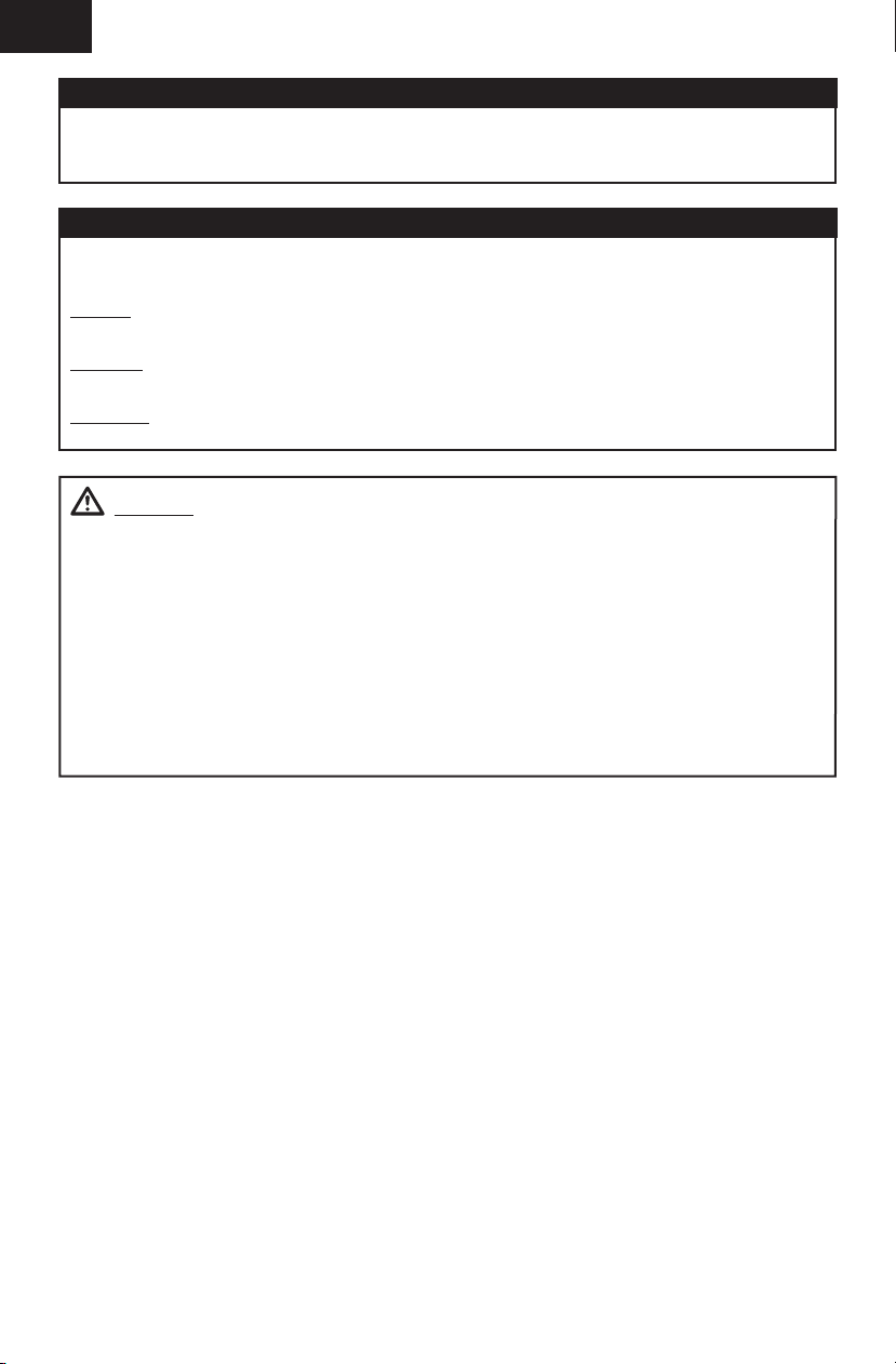
14.7 in (373mm)
To register your product online, go to www.e-fl iterc.com
2.1 oz (59.6 g)
12.7 in (323mm)
Installed
BL180 (Brushless) Outrunner Motor,
2500Kv (EFLUM180BL2)
™
DSM2 6Ch Ultra Micro AS3X
Receiver BL-ESC HT (EFLU4751)
(4) 2.3 g Performance Linear Long
Throw Servos (SPMSA2030L)
Battery: 180mAh 2S 20C Li-Po
(EFLB1802S20)
Battery Charger: 2S 7.4V Li-Po
(EFLUC1007)
Needed to Complete
Recommended Transmitter:
Spektrum™ DSM2™/DSMX® with
dual-rates and Expo (DX4e and up)
3
Page 4
EN
Prefl ight Checklist
1. Charge fl ight battery.
2. Install fl ight battery in aircraft
(once it has been fully charged).
3. Bind aircraft to transmitter.
4. Make sure linkages move freely.
5. Perform Control Direction Test with
transmitter.
AS3X Stabilization
DELIVERS BREAKTHROUGH PERFORMANCE
The AS3X System for airplanes is an electronic
enhancement system that makes it possible
for you to experience super-smooth fl ight
performance, yet still have full control authority
for sport, scale or 3D fl ight.
Turbulence, torque and tip stalls are just some of
the many complications to assess when trying to
achieve smooth fl ight. The Horizon Hobby worldclass team of RC pilots developed the AS3X System
for airplanes based on the successful use of AS3X
with ultra micro fl ybarless helicopters. Specially
6. Set dual rates and exponential.
7. Adjust center of gravity
8. Perform a radio system Range Check.
9. Find a safe and open area.
10. Plan fl ight for fl ying fi eld conditions.
tuned for airplanes, the AS3X System invisibly
helps with complicated corrections, allowing you
to experience ultra-smooth fl ight performance that
feels so natural that you’ll quickly build confi dence
in the capability of the airplane.
AS3X System setup is simple. Just bind your
™
DSM2
/DSMX® transmitter to the model using a
basic airplane program and AS3X will assure that
the locked-in feel and control authority you want is
instantly at your command to help show off your RC
pilot skills.
AS3X will innovate the way you’ll want to fl y now
and in the future. To see what we mean, go to
www.E-fl iteRC.com/AS3X.
Low Voltage Cutoff (LVC)
When a Li-Po battery is discharged below 3V per
cell, it will not hold a charge. The Hyper Taxi ESC
protects the fl ight battery from over-discharge using
Low Voltage Cutoff (LVC). Before the battery charge
decreases too much, LVC removes power supplied
to the motor. Power to the motor quickly decreases
and increases, showing that some battery power is
reserved for fl ight control and safe landing.
When the motor power pulses, land the aircraft
immediately and recharge the fl ight battery.
Disconnect and remove the Li-Po battery from the
aircraft after use to prevent trickle discharge. Before
storage, charge the Li-Po battery to full capacity.
4EN4
During storage, make sure the battery charge does
not fall below 3V per cell.
Tip: Due to the quiet nature of the aircraft, you may
not hear the pulsing of the motor.
For your fi rst fl ights, set your transmitter timer or a
stopwatch to 5 minutes. Adjust your timer for longer
or shorter fl ights once you have fl own the model.
NOTICE: Repeated fl ying to LVC will damage
the battery.
Page 5
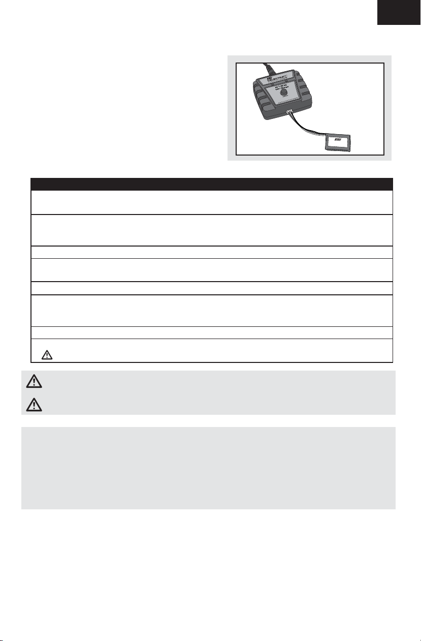
Charging the Battery
Your E-fl ite® Hyper Taxi™ comes with a 2-Cell 7.4V
180mAh 20C Li-Po battery and a Celectra
DC Li-Po Charger which requires a 12V (11V-14V)
DC power source.
Refer to battery warnings. It is recommended to
charge the battery pack while you are inspecting
the aircraft. The fl ight battery will be required to
confi rm proper aircraft operation in future steps.
Please visit www.horizonhobby.com for optional
battery adapters or AC power supplies.
The Battery Charging Process
1. Charge only batteries that are cool to the touch and are not damaged. Look at the battery to make
sure it is not damaged e.g., swollen, bent, broken or punctured.
2. The connector of the battery is specifically designed to allow it to fit into the charge port one way
to prevent reverse polarity connection. However, check for proper alignment and polarity before
proceeding to the next step.
3. Gently press the battery connector into the charge port located on the front of the charger.
4. When you make the connection successfully, the green LED blinking on the charger slows,
indicating proper connection.
5. Press the button on the charger. The red LED will illuminate, indicating charging has begun.
6. Charging a fully discharged (not over-discharged) 180mAh battery takes approximately 50–60
minutes at the included charger’s charge rate of 300mAh. The included battery can be charged at a
rate up to 3C (540mAh).
7. When the battery is fully charged, the green LED will turn solid.
8. Always unplug the battery from the charger immediately upon completion of charging.
CAUTION: Overcharging a battery can cause a fire.
™
2S 7.4V
2S 7.4V 180mAh 20C
Lithium Polymer Battery
EN
CAUTION: Only use a charger specifi cally designed to charge a Li-Po battery. Failure to do so could
result in fi re causing injury or property damage.
CAUTION: Never exceed the recommended charge rate.
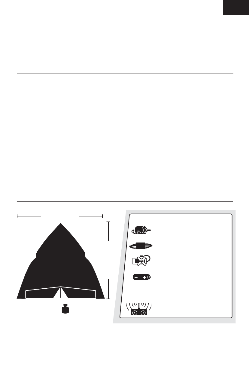
LED Functions under normal operation
1. Green LED blinking with power connected but without battery ...................................Standby
2. Green LED blinking .................................................................................................... Battery is connected
3. Blinking Red LED at varying speeds ........................................................................... Charging
4. Red and Green LED blinking simultaneously ............................................................... Balancing
5. Solid Green LED .......................................................................................................Full Charge
6. Red and Green LED fl ashing rapidly ........................................................................... Error
5
Page 6

EN
Battery Warnings
The Battery Charger (EFLUC1007) included with the
Hyper Taxi has been designed to safely charge the
Li-Po battery.
CAUTION: All instructions and warnings must
be followed exactly. Mishandling of Li-Po batteries
can result in a fi re, personal injury, and/or
property damage.
• By handling, charging or using the included Li-Po
battery you assume all risks associated with
lithium batteries.
• If at any time the battery begins to balloon or
swell, discontinue use immediately. If charging
or discharging, discontinue and disconnect.
Continuing to use, charge or discharge a battery
that is ballooning or swelling can result in fi re.
• Always store the battery at room temperature in a
dry area for best results.
• Always transport or temporarily store the battery
in a temperature range of 40–120º F. Do not store
battery or model in a car or direct sunlight. If
stored in a hot car, the battery can be damaged or
even catch fi re.
• Always charge batteries away from fl ammable
materials.
• NEVER USE AN Ni-Cd OR Ni-MH CHARGER. Failure
to charge the battery with a compatible charger
may cause fi re resulting in personal injury and/or
property damage
• Never discharge Li-Po cells to below 3V
under load.
• Never cover warning labels with hook and
loop strips.
• Never leave charging batteries unattended.
• Never charge batteries outside safe
temperature range.
• Never charge damaged batteries.
Transmitter and Receiver Binding
Binding is the process of programming the receiver of the control unit to recognize the GUID (Globally
Unique Identifi er) code of a single specifi c transmitter. You need to ‘bind’ your chosen SpektrumTM DSM2
®
DSMX
technology equipped aircraft transmitter to the receiver for proper operation.
Any JR® or Spektrum DSM2/DSMX transmitter can bind to the AS3X™ DSM® receiver. Due to the aerobatic
capabilities of the UMX™ Hyper Taxi™, it is highly recommended that you use a transmitter with exponential
and dual rates. Please visit www.bindnfl y.com for a complete list of compatible transmitters.
NOTICE: When using a Futaba
is required.
®
transmitter with a Spektrum DSM module, reversing the throttle channel
™
/
Binding Procedure
1. Refer to your transmitter’s unique instructions for binding to a receiver.
2. Make sure the fl ight battery is disconnected from the aircraft.
3. Power off the transmitter.
4. Connect the fl ight battery in the aircraft. The receiver LED will begin to fl ash rapidly, (typically after
5 seconds).
5. Make sure the transmitter controls are at neutral and the throttle and throttle trim are in the low
position.
6. Put your transmitter into bind mode. Refer to your transmitter’s manual for binding button or
switch instructions.
7. After 5 to 10 seconds, the receiver status LED will become solid, indicating that the receiver is
bound to the transmitter. If the LED does not turn solid, refer to the Troubleshooting
Guide at the back of the manual.
For subsequent fl ights, power on the transmitter for 5 seconds before connecting the fl ight battery.
6
Page 7
Installing the Flight Battery
1. Attach the flight battery to the hook and loop
strip under the cockpit. See the Adjusting the
Center of Gravity instructions for the battery’s
position.
2. Place the aircraft on the ground out of the wind
and then connect a fully charged flight battery.
Ensure the aircraft is immobile for 5 seconds
so the AS3X system initializes correctly. See
the Arming the ESC instructions for correct
connection of the battery to the ESC.
NOTICE: If using a different battery than a 2-Cell
7.4V 180mAh 20C Li-Po, you will need to apply a
piece of hook and loop fastener to the back of the
battery, opposite the side with the label, in order to
hold the battery in place.
CAUTION: Always disconnect the Li-Po
battery from the aircraft ESC when not fl ying to
avoid over-discharging the battery. Batteries
discharged to a voltage lower than the lowest
approved voltage may become damaged, resulting
in loss of performance and potential fi re when
Batteries are charged.
EN
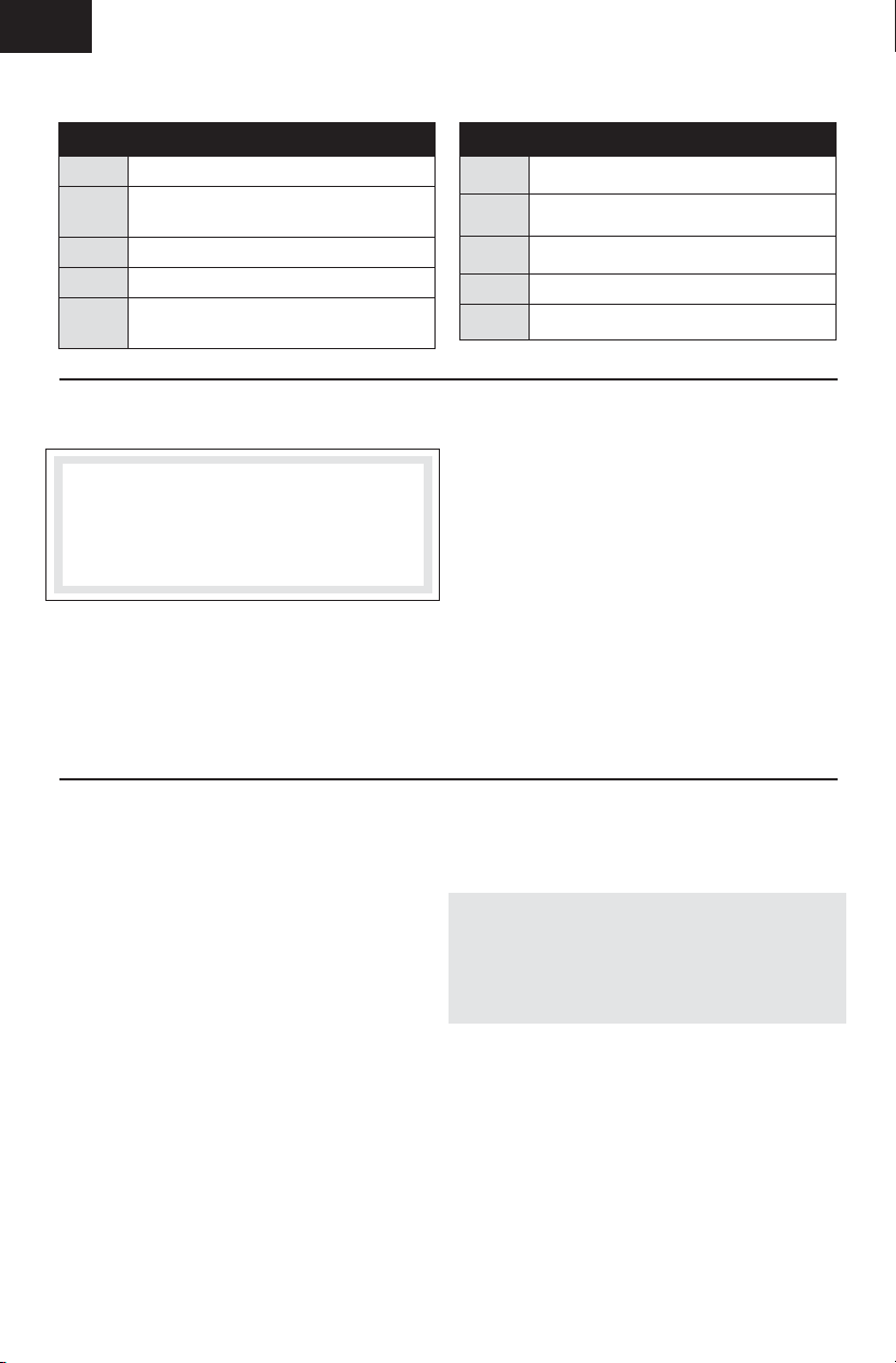
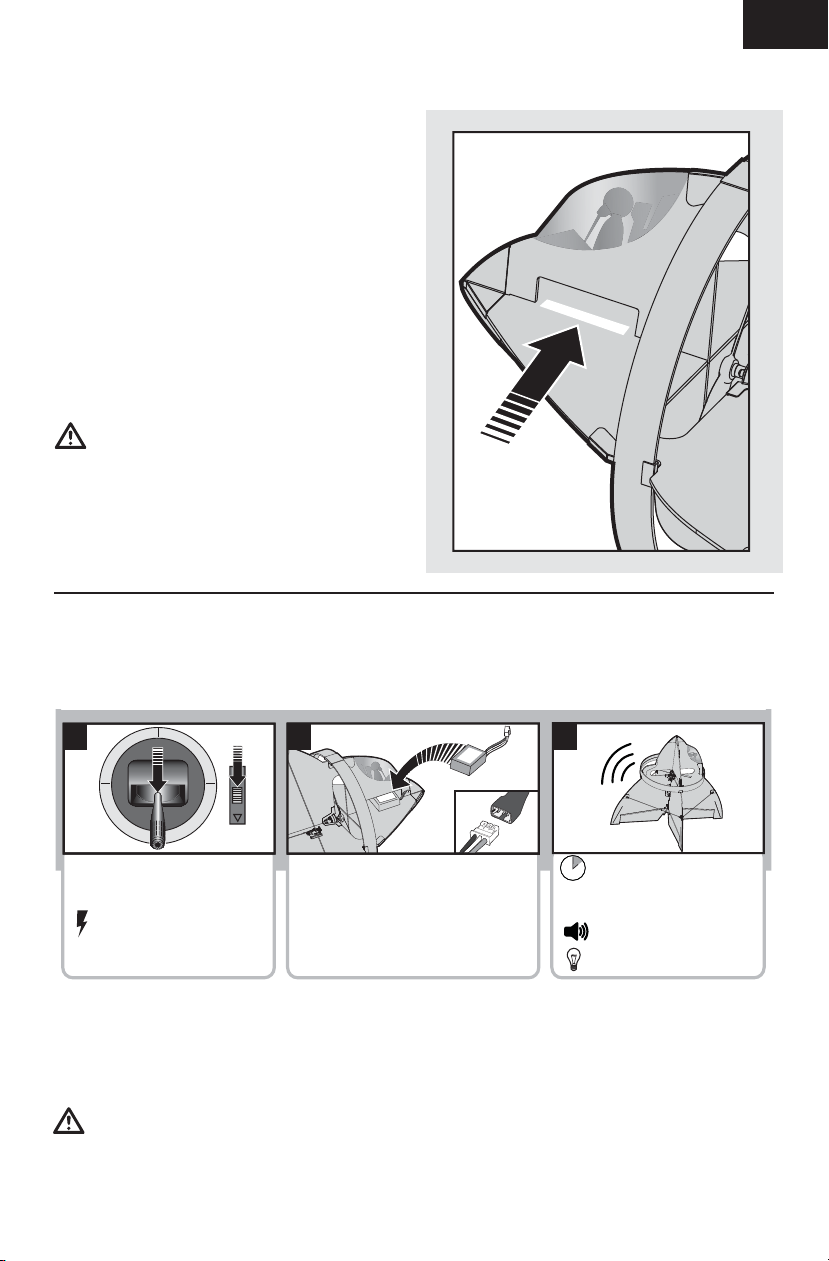
Arming the ESC
Arming the ESC also occurs after binding as previously described, but subsequent connection of a fl ight
battery requires the steps below.
1 2
Lower throttle and throttle
trim to lowest settings.
Power on the Transmitter
then wait 5 seconds
If you accidentally connect the battery while the throttle is fully raised, the ESC will enter programming
mode. Disconnect the battery immediately.
The AS3X system will not activate until the throttle stick or trim is increased for the fi rst time. Once the AS3X
is active, the control surfaces may move rapidly on the aircraft. This is normal.
AS3X will remain active until the battery is disconnected.
CAUTION: Always keep hands away from the propeller. When armed, the motor will turn the propeller
in response to any throttle movement.
Install fl ight battery and
connect it to the ESC.
3
Keep plane immobile
and away from wind for
5 seconds.
Series of tones
Continuous LED
7
Page 8

EN
Adjusting Center of Gravity (CG)
The CG location is 2mm from the rear edge of the
propeller slot.
The battery slot is oversized to allow for Center of
Gravity adjustment. Start by placing the battery at
the front edge of the battery slot with the connector
plug facing the front of the aircraft. Adjust as
needed by sliding the battery back or forward. You
may also turn the battery pack 90 degrees, bringing
the plug to the side.
2mm
Control Centering
Before the fi rst fl ights, or in the event of an
accident, make sure the fl ight control surfaces
are centered. Adjust the linkages mechanically if
the control surfaces are not centered. Use of the
transmitter sub-trims may not correctly center the
aircraft control surfaces due to the mechanical
limits of linear servos.
1. Make sure the control surfaces are neutral
when the transmitter controls and trims are
centered. The transmitter sub-trim must be
always be set to zero.
2. When needed, use a pair of pliers to carefully
bend the metal linkage (see illustration).
3. Make the U-shape narrower to make the
connector shorter. Make the U-shape wider
to make the linkage longer.
Settings for Control Horns
The following illustration shows the factory settings
for linkages on the control horns. After fl ying,
carefully adjust the linkage positions for the desired
control response.
CAUTION: Using settings other than the
factory settings, without proper experience, could
result in loss of control of your aircraft and a crash,
causing damage to the aircraft and personal injury.
Centering Controls After First Flights
For best performance with AS3X, it is important
that excessive trim is not used. If the model
requires excessive transmitter trim (4 or more clicks
of trim per channel), return the transmitter trim
to zero and adjust the linkages mechanically so
that the control surfaces are in the fl ight trimmed
position.
All Control Surfaces
8
Page 9

Control Direction Test
Bind your aircraft and transmitter before performing these tests. Move the controls on the transmitter to
make sure the aircraft control surfaces move correctly, freely, and in the proper direction.
Tip: Programming for the control surfaces has already been done in the receiver of the Hyper Taxi, so no
mixing is required in the transmitter.
To demonstrate modes 1–4, only the axis being tested is shown.
Always keep throttle at low position during testing.
EN
Up
Elevator
Left
Aileron
Down
Elevator
Right
Aileron
left
Rudder
Right
Rudder
9
Page 10

EN
Dual Rates and Expos
We recommend using a DSM radio capable of dual
rates and expo due to the aerobatic capabilities
of the Hyper Taxi. The settings shown here are
recommended starting settings. Adjust according to
individual preferences after initial fl ight.
If using the DX4e or DX5e transmitters, we
recommend activating Expo for smoother control.
For activation and deactivation of the Expo in the
DX4e and DX5e, see below.
NOTICE: Do not set your transmitter travel adjust
over 100%. If the TRAVEL ADJUST is set over
100%, it will not result in more control movement, it
will overdrive the servo and cause damage.
It is normal for linear servos to make signifi cant
noise. The noise is not an indication of a
faulty servo.
Aileron 100% 65%
Elevator 100% 70%
Dual Rates
Rudder 100% 70%
Aileron 25% 10%
Elevator 25% 10%
Expos
Rudder 25% 10%
Tip: For the fi rst few fl ights, fl y the model on
low rate.
High Rate Low Rate
High Rate Low Rate
DX4e and DX5e Expo Activation and Deactivation
If you plan to fl y your Hyper Taxi with a DX4e or DX5e, disconnect the battery from the aircraft before
activating the Expo feature in your transmitter.
Once Expo is activated, it will remain activated for use through subsequent power cycles of the transmitter.
Once Expo is deactivated, it will remain deactivated until it is activated again.
DX4e (Modes 1 and 2)
Activate and Deactivate Expo
1. Put the ACT switch in the down position
(ON) and the Rate switch in the down
position (LO).
2. Push and hold the trainer (bind) button
and move and hold the two sticks (as
shown here for activation (A) or
deactivation (B)), while powering on
the transmitter.
3. Release the trainer switch and the
control sticks only after a series of
tones sound (ascending tones for
activation, descending tones for
deactivation).
A
B
DX5e (Modes 1 and 2)
Activate Expo
1. Hold the aileron trim switch to the right when
powering on the transmitter.
2. Release the aileron trim switch after a series
of ascending tones to confirm that Expo is
activated.
10
Deactivate Expo
1. Hold the aileron trim switch to the left when
powering on the transmitter.
2. Release the aileron trim switch after a series
of descending tones to confirm that Expo is
deactivated.
Page 11

Flying Tips and Repairs
EN
Flying
We recommend fl ying your E-fl ite® Hyper Taxi
™
indoors or outside only in 8 mph (13 km) winds
or less. Always avoid fl ying near houses, trees,
wires and buildings. You should also be careful to
avoid fl ying in areas where there are many people,
such as busy parks, schoolyards or soccer fi elds.
Consult local laws and ordinances before choosing a
location to fl y your aircraft.
Takeoff
For the fi rst fl ew fl ights, we recommend hand
launching the model, as this can be easier to do
than a takeoff from the ground.
Hand Launch
Hold the Hyper Taxi upright by the canopy. Apply
1/2–3/4 throttle, and gently toss the aircraft into the
wind with the wings level. After the model leaves
your hand, apply more throttle and begin to enjoy
your E-fl ite Hyper Taxi.
Vertical Takeoff
Place the Hyper Taxi in position for takeoff (sitting
on the rear tips of the wings) with the with the
grey side of the aircraft facing into the wind. Apply
throttle to the Hyper Taxi
™
until it begins to leave the
ground. Add full power and a small amount of down
elevator until the model is fl ying straight and level.
Turning
This model is much different than any other
model you may have fl own. Because of its nearly
symmetrical shape, it fl ies very neutral while it
is on its side in knife edge fl ight. Because of this,
turning requires the use of rudder. Roll the model to
a small bank angle in the direction you would like
to turn. Once this angle is established, apply rudder
in the same direction that the ailerons were applied
while simultaneously beginning to add elevator
to maintain altitude. Adjust your turning radius by
the amount of initial bank angle and the amount of
rudder and elevator applied while making the turn.
Feel free to experiment with fl ying the Hyper Taxi
with the wings at various angles; however, be aware
that the model acts very similarly on its side as it
does when fl ying upright.
Landing
Intermediate Vertical Landing
Fly the Hyper Taxi down to approximately one length
of the model above the ground. Aggressively fl are
the model with the elevator. As the model rotates to
vertical, the throttle will control your descent speed,
rather than the elevator. Add more power to climb
or slow your descent. Reduce your throttle input to
descend or speed up your descent. Ease off of the
power as the model comes to rest on the tips of
the wings.
Advanced Vertical Landing
When you become accustomed to fl ying the Hyper
Taxi, you may want to attempt an advanced vertical
landing. If you are experienced with 3D fl ight, you
may choose to hover the model like a 3D airplane
and bring the model to rest on its wingtips by using
throttle to adjust the model’s altitude. To hover
vertically, use a combination of rudder/elevator.
Failure to lower the throttle stick and trim to the
lowest possible positions during a crash could result
in damage to the ESC in the receiver unit, which
may require replacement.
Over Current Protection (OPC)
The Hyper Taxi is equipped with Over Current
Protection (OCP). This feature protects the ESC
from overheating. OCP stops the motor when the
transmitter throttle is set too high and the propeller
cannot turn. The OCP will only activate when the
throttle is positioned just above 1/2 throttle. After
the ESC stops the motor, fully lower the throttle to
re-arm the ESC.
Repairs
Crash damage is not covered under warranty.
Repair the Hyper Taxi using foam-compatible CA
glue or clear tape. Only use foam-compatible CA
glue as other types of glue can damage the foam.
When parts are not repairable, see the Replacement
Parts List for ordering by item number.
For a listing of all replacement and optional parts,
refer to the list at the back of this manual.
NOTICE: Use of foam-compatible CA accelerant on
your model can damage printing. DO NOT handle
the model until accelerant fully dries.
11
Page 12

EN
Additional Safety Precautions and Warnings
As the user of this product, you are solely
responsible for operating in a manner that does
not endanger yourself and others or result in
damage to the product or the property of others.
• Always keep a safe distance in all directions
around your model to avoid collisions or injury.
• Always operate your model in open spaces away
from full-size vehicles, traffi c and people.
• Always carefully follow the directions and
warnings for this and any optional support
equipment (chargers, rechargeable battery
packs, etc.).
• Always keep all chemicals, small parts and
anything electrical out of the reach of children.
Post Flight Checklist
1. Disconnect fl ight battery from ESC
(Required for Safety and battery life).
2. Power off transmitter.
3. Remove fl ight battery from aircraft.
4. Recharge fl ight battery.
This model is controlled by a radio signal subject
to interference from many sources outside your
control. This interference can cause momentary loss
of control, so it is advisable to always keep a safe
distance in all directions around your model as this
space will help avoid collisions or injury.
• Always avoid water exposure to all equipment
not specifi cally designed and protected for this
purpose. Moisture causes damage to electronics.
• Never place any portion of the model in your
mouth as it could cause serious injury or
even death.
• Never operate your model with low transmitter
batteries.
5. Store fl ight battery apart from aircraft
and monitor the battery charge.
6. Make note of fl ight conditions and
fl ight plan results, planning for
future fl ights.
12
Page 13

Service of Power Components
EN
CAUTION: DO NOT handle propeller parts
while the fl ight battery is connected.
Personal injury could result.
1. Gently hold the nose of the aircraft and remove
the prop screw (A), propeller (B) and propeller
spacer (C) from the motor shaft (D). Hold the
motor so it does not turn when the screw is
turned.
2. Disconnect the motor wires from the ESC
wires.
3. Remove the screw (E) and the motor (F) from
the motor mount (G) on the fuselage.
A
B
C
D
F
4. Assemble in reverse order. Correctly align
the wire colors and connect the motor to
the ESC. Install the propeller with numbers
facing to the front of the aircraft.
G
E
13
Page 14

EN
Troubleshooting Guide
AS3X
Problem Possible Cause Solution
Control surfaces not
at neutral position
when transmitter
controls are at neutral
Model fl ies inconsistently from fl ight
to fl ight
Airplane oscillates in
roll, yaw or pitch
Problem Possible Cause Solution
Aircraft will not
respond to throttle
but responds to other
controls
Extra propeller noise
or extra vibration.
Reduced fl ight time
or aircraft underpowered.
LED on receiver
fl ashes and aircraft
will not bind to
transmitter (during
binding).
LED on receiver
fl ashes rapidly and
aircraft will not respond to transmitter
(after binding).
Control surfaces may not have been mechanically centered from factory
Aircraft was moved after the fl ight battery
was connected and before sensors initialized
Trims are moved too far from neutral
position
Damaged propeller, spinner or motor, causing vibration in the airframe
Prop screw is too loose, causing
vibration
Throttle stick and/or throttle trim too high Reset controls with throttle stick and throttle
Throttle channel is reversed Reverse throttle channel on transmitter
Motor disconnected from receiver Make sure motor is connected to the receiver
Damaged propeller, spinner or motor Replace damaged parts
Prop screw is too loose Tighten the prop screw
Flight battery charge is low Completely recharge fl ight battery
Propeller installed backwards Install propeller with numbers facing forward
Flight battery damaged Replace fl ight battery and follow fl ight battery
Flight conditions may be too cold Make sure battery is warm before use
Battery capacity too low for fl ight conditions Replace battery or use a larger capacity battery
Transmitter too near aircraft during binding
process
Bind switch or button not held long enough
during bind process
Less than a 5-second wait between fi rst
powering on transmitter and connecting
fl ight battery to aircraft
Aircraft bound to different model memory
(ModelMatch
Flight battery/transmitter battery charge is
too low
TM
radios only)
Center control surfaces mechanically by adjusting the u-bends on control linkages
Disconnect and reconnect the fl ight battery
while keeping the aircraft still for 5 seconds
Neutralize trims and mechanically adjust linkages to center control surfaces
Replace damaged parts
Tighten the prop screw
trim at lowest setting
instructions
Power off transmitter, move transmitter a larger
distance from aircraft, disconnect and reconnect fl ight battery to aircraft and follow binding
instructions
Power off transmitter and repeat bind process.
Hold transmitter bind button or switch until
receiver is bound
Leaving transmitter on, disconnect and reconnect fl ight battery to aircraft
Select correct model memory on transmitter
and disconnect and reconnect fl ight battery to
aircraft
Replace/recharge batteries
14
Page 15

Troubleshooting Guide (Continued)
Problem Possible Cause Solution
Control surface does
not move
Controls reversed Transmitter settings reversed Do the Control Direction Test and adjust
Motor loses power Damage to motor or power components Do a check of motor and power components
Motor power quickly
decreases and
increases then motor
loses power
Motor/ESC is not
armed after landing
Servo locks or freezes
at full travel
Control surface, control horn, linkage or
servo damage
Wire damaged or connections loose Do a check of wires and connections, connect
Flight battery charge is low Fully recharge or replace fl ight battery
Control linkage does not move freely Make sure control linkage moves freely
Battery power is down to the point of
receiver/ESC Low Voltage Cutoff (LVC)
Over Current Protection (OCP) stops the
motor when the transmitter throttle is set
high and the propeller cannot turn
Travel adjust value is set above 100%
overdriving the servo
Replace or repair damaged parts and adjust
controls
or replace as needed
controls on transmitter appropriately
for damage (replace as needed)
Recharge fl ight battery or replace battery that
is no longer performing
Fully lower throttle and throttle trim to arm ESC
Set Travel adjust to 100% or less and/or set
sub-trims to Zero and adjust linkages
mechanically
EN
15
Page 16

EN
Limited Warranty
What this Warranty Covers
Horizon Hobby, Inc. (“Horizon”) warrants to the original
purchaser that the product purchased (the “Product”) will
be free from defects in materials and workmanship at the
date of purchase.
What is Not Covered
This warranty is not transferable and does not cover (i)
cosmetic damage, (ii) damage due to acts of God, accident, misuse, abuse, negligence, commercial use, or due
to improper use, installation, operation or maintenance,
(iii) modifi cation of or to any part of the Product, (iv)
attempted service by anyone other than a Horizon Hobby
authorized service center, or (v) Products not purchased
from an authorized Horizon dealer.
OTHER THAN THE EXPRESS WARRANTY ABOVE, HORIZON
MAKES NO OTHER WARRANTY OR REPRESENTATION, AND
HEREBY DISCLAIMS ANY AND ALL IMPLIED WARRANTIES,
INCLUDING, WITHOUT LIMITATION, THE IMPLIED
WARRANTIES OF NON-INFRINGEMENT, MERCHANTABILITY
AND FITNESS FOR A PARTICULAR PURPOSE. THE
PURCHASER ACKNOWLEDGES THAT THEY ALONE HAVE
DETERMINED THAT THE PRODUCT WILL SUITABLY MEET
THE REQUIREMENTS OF THE PURCHASER’S
INTENDED USE.
Purchaser’s Remedy
Horizon’s sole obligation and purchaser’s sole and
exclusive remedy shall be that Horizon will, at its option,
either (i) service, or (ii) replace, any Product determined
by Horizon to be defective. Horizon reserves the right
to inspect any and all Product(s) involved in a warranty
claim. Service or replacement decisions are at the sole
discretion of Horizon. Proof of purchase is required for
all warranty claims. SERVICE OR REPLACEMENT AS
PROVIDED UNDER THIS WARRANTY IS THE PURCHASER’S
SOLE AND EXCLUSIVE REMEDY.
Limitation of Liability
HORIZON SHALL NOT BE LIABLE FOR SPECIAL, INDIRECT,
INCIDENTAL OR CONSEQUENTIAL DAMAGES, LOSS OF
PROFITS OR PRODUCTION OR COMMERCIAL LOSS IN ANY
WAY, REGARDLESS OF WHETHER SUCH CLAIM IS BASED
IN CONTRACT, WARRANTY, TORT, NEGLIGENCE, STRICT
LIABILITY OR ANY OTHER THEORY OF LIABILITY, EVEN IF
HORIZON HAS BEEN ADVISED OF THE POSSIBILITY OF
SUCH DAMAGES. Further, in no event shall the liability
of Horizon exceed the individual price of the Product on
which liability is asserted. As Horizon has no control over
use, setup, final assembly, modification or misuse, no
liability shall be assumed nor accepted for any resulting
damage or injury. By the act of use, setup or assembly,
the user accepts all resulting liability. If you as the purchaser or user are not prepared to accept the liability
associated with the use of the Product, purchaser is
advised to return the Product immediately in new and
unused condition to the place of purchase.
Law
These terms are governed by Illinois law (without regard
to conflict of law principals). This warranty gives you
specific legal rights, and you may also have other rights
which vary from state to state. Horizon reserves the right
to change or modify this warranty at any time without
notice.
16
Warranty Services
Questions, Assistance, and Services
Your local hobby store and/or place of purchase cannot
provide mwarranty support or service. Once assembly,
setup or use of the Product has been started, you must
contact your local distributor or Horizon directly. This will
enable Horizon to better answer your questions and
service you in the event that you may need any
assistance. For questions or assistance, please direct
your email to productsupport@ horizonhobby.com, or
call 877.504.0233 toll free to speak to a Product Support
representative. You may also find information on our
website at www.horizonhobby.com.
Inspection or Services
If this Product needs to be inspected or serviced, please
use the Horizon Online Service Request submission
process found on our website or call Horizon to obtain a
Return Merchandise Authorization (RMA) number. Pack
the Product securely using a shipping carton. Please note
that original boxes may be included, but are not designed
to withstand the rigors of shipping without additional
protection. Ship via a carrier that provides tracking and
insurance for lost or damaged parcels, as Horizon is
not responsible for merchandise until it arrives and is
accepted at our facility. An Online Service Request is
available at www.horizonhobby.com under the Support
tab. If you do not have internet access, please contact
Horizon Product Support to obtain a RMA number along
with instructions for submitting your product for service.
When calling Horizon, you will be asked to provide your
complete name, street address, email address and phone
number where you can be reached during business hours.
When sending product into Horizon, please include your
RMA number, a list of the included items, and a brief summary of the problem. A copy of your original sales receipt
must be included for warranty consideration. Be sure your
name, address, and RMA number are clearly written on
the outside of the shipping carton.
Notice: Do not ship LiPo batteries to Horizon. If you
have any issue with a LiPo battery, please contact the
appropriate Horizon Product Support office.
Warranty Requirements
For Warranty consideration, you must include your
original sales receipt verifying the proof-ofpurchase date. Provided warranty conditions have
been met, your Product will be serviced or replaced free
of charge. Service or replacement decisions are at the
sole discretion of Horizon.
Non-Warranty Service
Should your service not be covered by warranty
service will be completed and payment will be
required without notification or estimate of the
expense unless the expense exceeds 50% of the retail
purchase cost. By submitting the item for service you are
agreeing to payment of the service without notification.
Service estimates are available upon request. You must
include this request with your item submitted for service.
Non-warranty service estimates will be billed a minimum
of ½ hour of labor. In addition you will be billed for return
freight. Horizon accepts money orders and cashiers
checks, as well as Visa, MasterCard, American Express,
and Discover cards. By submitting any item to Horizon
for service, you are agreeing to Horizon’s Terms and
Conditions found on our website www.horizonhobby.com/
Service/Request/.
Page 17

Warranty and Service Information
Country of
Purchase
United States
of America
United Kingdom Horizon Hobby Limited
Germany
France Horizon Hobby SAS
Horizon Hobby Address Phone Number/Email Address
Horizon Service Center
(Electronics and engines)
Horizon Product Support
(All other products)
Horizon Technischer
Service
4105 Fieldstone Rd
Champaign, Illinois
61822 USA
4105 Fieldstone Rd
Champaign, Illinois
61822 USA
Units 1-4 Ployters Rd
Staple Tye
Harlow, Essex
CM18 7NS
United Kingdom
Christian-Junge-Straße1
25337 Elmshorn, Germany
14 Rue Gustave Eiffel
Zone d’Activité du Réveil Matin
91230 Montgeron
877-504-0233
Online Repair Request visit:
www.horizonhobby.com/service
877-504-0233
productsupport@horizonhobby.com
+44 (0) 1279 641 097
sales@horizonhobby.co.uk
+49 (0) 4121 2655 100
service@horizonhobby.de
+33 (0) 1 60 47 44 70
infofrance@horizonhobby.com
Compliance Information for the European Union
Declaration of Conformity
(in accordance with ISO/IEC 17050-1)
No. HH2011101301
EN
Product(s): UMX Hyper Taxi BNF
Item Number(s): EFLU4780
Equipment class: 1
The object of declaration described above is in conformity with the requirements of the specifi cations listed
below, following the provisions of the European R&TTE directive 1999/5/EC and EMC Directive 2004/108/EC:
EN 301 489-1 V1.7.1: 2006
EN 301 489-17 V1.3.2: 2008
EN55022: 2010
EN55024: 2010
Signed for and on behalf of:
Horizon Hobby, Inc.
Champaign, IL USA
Oct 13, 2011
International Operations and Risk Management
Steven A. Hall
Vice President
Horizon Hobby, Inc.
Instructions for disposal of WEEE by users in the European Union
This product must not be disposed of with other waste. Instead, it is the user’s responsibility
to dispose of their waste equipment by handing it over to a designated collections point
for the recycling of waste electrical and electronic equipment. The separate collection and
recycling of your waste equipment at the time of disposal will help to conserve natural
environment. For more information about where you can drop off your waste equipment for recycling, please
contact your local city offi ce, your household waste disposal service or where you purchased the product.
resources and ensure that it is recycled in a manner that protects human health and the
17
Page 18

Istruzioni per lo smaltimento di RAEE da parte di utenti dell’Unione Europea
Questo prodotto non deve essere smaltito insieme ai rifi uti domestici. Al contrario, è
responsabilità dell’utente lo smaltimento di tali rifi uti, che devono essere portati in un centro
di raccolta designato per il riciclaggio di rifi uti elettrici e apparecchiature elettroniche. Al
momento dello smaltimento, la raccolta diff erenziata e il riciclaggio dei rifi uti provenienti da
apparecchiature contribuiscono a preservare le risorse naturali e garantiscono un riciclaggio
adatto a proteggere la salute e l’ambiente. Per maggiori informazioni sui punti di riciclaggio, contattare
il proprio uffi cio locale, il servizio di smaltimento rifi uti o il negozio presso il quale è stato acquistato il
prodotto.
– Replacement Parts –
– Ersatzteile –
– Piéces de rechange –
– Recapiti per i ricambi –
IT
Part # • Nummer
Numéro • Codice
EFLU4770
EFLU4751
EFLU4756
EFLU4725
EFLUP55200
EFLUM180BL2
EFLB1802S20
EFLUC1007
EFLUC1008
SPMSA2030L
SPM6836
Description Beschreibung Description Descrizione
Replacement
Airframe: UMX
Hyper Taxi
DSM2 6Ch Ultra
Micro AS3X Receiver BL-ESC HT
Hardware Set: UMX
Hyper Taxi
Pushrod Set: UMX
Hyper Taxi
5.5X2.0 Electric
Propeller: UMX
Hyper Taxi
180 Brushless
Outrunner Motor
2500Kv
180mAh 2S 7.4V
20C Li-Po, 26AWG
Celectra 2S 7.4V DC
Li-Po Charger
Power Cord for
EFLUC1007
2.3-Gram Performance Linear Long
Throw Servo
Replacement Servo
Mechanics: 2.3Gram 2030L
Ersatzrumpf : UMX
Hyper Taxi
DSM2 6Kanal Ultra
Micro AS3X Empfänger BL Regler
BL-ESC HT
Kleinteile Set: UMX
Hyper Taxi
Gestänge Set: UMX
Hyper Taxi
5.5X2.0
Propeller: UMX
Hyper Taxi
180 Brushless
Außenläufer Motor
2500Kv
180mAh 2S 7.4V
20C Li-Po Akku,
26AWG
Celectra 2S 7.4V DC
Li-Po Ladegerät
Anschlußstecker mit
Krokodilklemmen für
EFLUC1007
Spektrum 2.3g Linear
Servo, Weg lang
Austausch Servo
Mechanik: 2.3Gram
2030L
Structure: UMX Hyper
Taxi
Ultra micro récepteur
6 voies AS3X avec
contrôleur BL intégré.
Accessoires: UMX
Hyper Taxi
Tringleries: UMX Hyper
Taxi
Hélice 5.5x2.0: UMX
Hyper Taxi
Moteur brushless
180 à cage tournante
2500KV
Batterie Li-Po 7.4V 2S
180mA 20C
Chargeur Li-Po Celectra DC 7.4V 2S
Câble d’alimentation
pour EFLUC1007
Servo linéaire 2.3g
longue course
Mécanique de remplacement pour servo
2.3g 2030L
Telaio di ricambio: UMX
Hyper Taxi
Ricevitore 6Ch DSM2
Ultra Micro AS3X BLESC HT
Set viti: UMX Hyper Taxi
Set comandi: UMX
Hyper Taxi
Elica per elettrico
5.5X2.0: UMX Hyper
Taxi
Motore brushless a
cassa rotante180
2500Kv
Batteria 180mAh 2S
7.4V 20C Li-Po, 26AWG
Caricabatterie Celectra
2S 7.4V DC Li-Po
Cavetto per
EFLUC1007
Servo lineare a corsa
lunga 2.3-Gram
Meccanica di ricambio
per servo: 2.3- Gram
2030L
65
Page 19

Optional Parts and Accessories –
– Optionale Bauteile und Zubehörteile –
– Piéces optionnelles et accessoires –
– Parti opzionali e accessori –
Part # • Nummer
Numéro • Codice
EFLA700UM
EFLA7001UM
EFLU4068
EFLB2002S25
SPM6825
ELFC4000
EFLC4000UK
EFLC4000AU
EFLC4000EU
SPMR5510
SPMR55101
SPMR6610
SPMR66101
SPMR6610E
SPMR66101E
SPM7800
Description Beschreibung Description Descrizione
Charger Plug Adapter:
EFL
Charger Plug Adapter: TPLadekabel Adapter TP Prise d’adaptation
Harness Adapter: UMX
Beast
200mAh 2S 7.4V 25C
Li-Po, 26AWG
AS2000 Servo
Reverser
AC to 12V DC, 1.5
Amp Power Supply
(US)
AC to 12V DC,1.5 Amp
Power Supply (UK)
AC to 12V DC,1.5 Amp
Power Supply (AU)
AC to 12V DC,1.5 Amp
Power Supply (EU)
DX5e DSMX 5-Channel Transmitter only
Mode 2
DX5e DSMX 5-Channel Transmitter only
Mode 1
DX6i DSMX 6-Channel
Transmitter only
Mode 2
DX6i DSMX 6-Channel
Transmitter only
Mode 1
DX6i DSMX 6-Channel
Transmitter only Mode
2 (EU)
DX6i DSMX 6-Channel
Transmitter only Mode
1 (EU)
DX7s DSMX
7-Channel Transmitter
Mode 2
Ladekabel Adapter
EFL
E-fl ite UMX Beast
Y-Kabel
200mAh 2S 7.4V 25C
Li-Po, 26AWG
AS2000 Servoreverser
AC to 12V DC,1.5
Amp Power Supply
(US)
AC to 12V DC,1.5
Amp Power Supply
(UK)
AC to 12V DC,1.5
Amp Power Supply
(AU)
AC auf 12V DC,1.5
Amp Netzgerät (EU)
DX5e DSMX 5-Kanal
Sender ohne Empfänger Mode 2
DX5e DSMX 5-Kanal
Sender ohne Empfänger Mode 1
DX6i DSMX 6-Kanal
Sender ohne Empfänger Mode 2
DX6i DSMX 6-Kanal
Sender ohne Empfänger Mode 1
Spektrum DX6i
DSMX Sender ohne
Empfänger MD2
Spektrum DX6i
DSMX Sender ohne
Empfänger MD1
Spektrum DX7s 7
Kanal Sender
Prise d’adaptation
chargeur: EFL
chargeur: TP
Adaptateur de
câblage: UMX Beast
Batterie Li-Po 7.4V
2S 200mA 25c
AS2000 Inverseur de
servo
Alimentation secteur
(US)
Alimentation secteur
12V DC 1.5A (UK)
Alimentation secteur
12V DC 1.5A (AU)
Alimentation secteur
12V DC 1.5Ay (EU)
Emetteur seul DX5e
DSMX 5 voies Mode 2
Emetteur seul DX5e
DSMX 5 voies Mode 1
Emetteur seul DX6i
DSMX 6 voies Mode 2
Emetteur seul DX6i
DSMX 6 voies Mode 1
DX6i DSMX 6-Channel Transmitter only
Mode 2 (EU)
Emetteur seul DX6i
DSMX 6 voies Mode
1 (EU)
Emetteur DX7s DSMX
7 voies Mode 2
Adattatore per la
carica: EFL
Adattatore per la
carica: TP
Cavo adattatore: UMX
Beast
Batteria 200mAh
2S 7.4V 25C Li-Po,
26AWG
Inversore per servo
AS2000
Alimentatore AC to
12V DC, 1.5 Amp (US)
Alimentatore AC to
12V DC,1.5 Amp (UK)
Alimentatore AC to
12V DC,1.5 Amp (AU)
Alimentatore AC to
12V DC,1.5 Amp (EU)
Solo trasmettitore
DX5e DSMX 5-Ch
Mode 2
Solo trasmettitore
DX5e DSMX 5-Ch
Mode 1
Solo trasmettitore
DX6i DSMX 6-Ch
Mode 2
Solo trasmettitore
DX6i DSMX 6-Ch
Mode 1
Solo trasmettitore
DX6i DSMX 6-Ch
Mode 2 (EU)
Solo trasmettitore
DX6i DSMX 6-Ch
Mode 1 (EU)
Trasmettitore DX7s
DSMX 7-Ch Mode 2
66
Page 20

Part # • Nummer
Numéro • Codice
SPM7800EU
SPM78001AU
SPM78001EU
*SPMR8800
*SPMR8800EU
*SPMR88001AU
*SPMR88001EU
Description Beschreibung Description Descrizione
DX7s DSMX
7-Channel Transmitter
Mode 2 (EU)
DX7s DSMX
7-Channel Transmitter
Mode 1 (AU)
DX7s DSMX
7-Channel Transmitter
Mode 1 (EU)
DX8 DSMX
Transmitter Only
Mode 2
DX8 DSMX
Transmitter Only
Mode 2 (EU)
DX8 DSMX
Transmitter Only
Mode 1 (AU)
DX8 DSMX
Transmitter Only
Mode 1 (EU)
Spektrum DX7s 7
Kanal Sender
DX7s DSMX
7-Channel
Transmitter Mode
1 (AU)
DX7s DSMX
7-Channel
Transmitter Mode
1 (AU)
Spektrum DX8 nur
Sender Mode 1-4
Spektrum DX8 nur
Sender Mode 1-4
DX8 DSMX
Transmitter Only
Mode 1 (AU)
DX8 DSMX nur
Sender Mode 1 (EU)
Emetteur DX7s DSMX
7 voies Mode 1(EU)
Emetteur DX7s DSMX
7 voies Mode 1 (AU)
Emetteur DX7s DSMX
7 voies Mode 1 (EU)
Emetteur seul DX8
DSMX 8 voies
Mode 2
Emetteur seul DX8
DSMX 8 voies Mode
2 (EU)
Emetteur seul DX8
DSMX 8 voies Mode
1(AU)
Emetteur seul DX8
DSMX 8 voies Mode
1 (EU)
* All Spektrum DX8 transmitters can be set up for modes 1–4
* Alle Spektrum DX8 Sender können für Mode 1–4 eingestellt werden
* Tous les émetteurs Spektrum DX8 peuvent êtres paramétrés dans les 4 modes
* Tutti i trasmettitori Spektrum DX8 possono essere confi gurati per i modelli 1–4
Trasmettitore DX7s
DSMX 7-Ch Mode
2 (EU)
Trasmettitore DX7s
DSMX 7-Ch Mode
1 (AU)
Trasmettitore DX7s
DSMX 7-Ch Mode
1 (EU)
Solo trasmettitore
DX8 DSMX Mode 2
Solo trasmettitore
DX8 DSMX Mode
2 (EU)
Solo trasmettitore
DX8 DSMX Mode
1 (AU)
Solo trasmettitore
DX8 DSMX Mode
1 (EU)
– Parts Contact Information –
– Intaktinformationen für Ersatzteile –
– Coordonnés pour obtenir de piéces détachées –
– Recapiti per i ricambi –
Country of Purchase Horizon Hobby Address Phone Number/Email Address
United States Sales
United Kingdom Horizon Hobby Limited
Germany Horizon Hobby GmbH
France Horizon Hobby SAS
China Horizon Hobby – China
4105 Fieldstone Rd
Champaign, Illinois, 61822 USA
Units 1-4 Ployters Rd
Staple Tye
Harlow, Essex
CM18 7NS, United Kingdom
Christian-Junge-Straße 1
25337 Elmshorn, Germany
14 Rue Gustave Eiffel
Zone d’Activité du Réveil Matin
91230 Montgeron
Room 506, No. 97 Changshou Rd.
Shanghai, China, 200060
800-338-4639
sales@horizonhobby.com
+44 (0) 1279 641 097
sales@horizonhobby.co.uk
+49 4121 46199 60
service@horizonhobby.de
+33 (0) 1 60 47 44 70
infofrance@horizonhobby.com
+86 (021) 5180 9868
info@horizonhobby.com.cn
67
Page 21

© 2011 Horizon Hobby, Inc.
UMX, AS3X, E-fl ite, Hyper Taxi, JR, Celectra, DSM2, DSMX, ModelMatch and Bind-N-Fly
are trademarks or registered trademarks of Horizon Hobby, Inc.
The Spektrum trademark is used with permission of Bachmann Industries, Inc.
Futaba is a registered trademark of Futaba Denshi Kogyo Kabushiki Kaisha
Corporation of Japan.
US D578,146. PRC ZL 200720069025.2. US 7,898,130 Other patents pending.
www.e-fl iterc.com
Created 10/11 33105
 Loading...