

Page 1

INSTRUCTION MANUAL
Specifications:
• Wingspan:................................................................................................................ 87 in (220 cm)
• Overall Length:...................................................................................................... 41 in (104 cm)
• Wing Area:................................................................................................ 566 sq in (36.5 dm sq)
• Weight (Approx.) (with 6-cell batter y pack): ................................ 52-55 oz (1473-1550 g)
• 90% ARF almost ready-to-fly
• Precovered with Solarfilm
™
• All hardware included
• Prewired switch harness and motor installed
TM
TM
Page 2

2
Table of C on ten ts
Introduction . . . . . . . . . . . . . . . . . . . . . . . . . . . . . . . . . . . . . . . . . . . . . . . . . . . . . . . . . . . . . . . . . . . . . . . . . . . . . . . . . . . . . . . . . 3
Notes & Warnings. . . . . . . . . . . . . . . . . . . . . . . . . . . . . . . . . . . . . . . . . . . . . . . . . . . . . . . . . . . . . . . . . . . . . . . . . . . . . . . . . . . . . 3
Additional Required Equipment . . . . . . . . . . . . . . . . . . . . . . . . . . . . . . . . . . . . . . . . . . . . . . . . . . . . . . . . . . . . . . . . . . . . . . . . . . . 4
Radio Equipment. . . . . . . . . . . . . . . . . . . . . . . . . . . . . . . . . . . . . . . . . . . . . . . . . . . . . . . . . . . . . . . . . . . . . . . . . . . . . . . . . . . . . . 4
Field Equipment . . . . . . . . . . . . . . . . . . . . . . . . . . . . . . . . . . . . . . . . . . . . . . . . . . . . . . . . . . . . . . . . . . . . . . . . . . . . . . . . . . . . . . 5
Optional Field Equipment . . . . . . . . . . . . . . . . . . . . . . . . . . . . . . . . . . . . . . . . . . . . . . . . . . . . . . . . . . . . . . . . . . . . . . . . . . . . . . . 5
Required Tools, Supplies, and Adhesives . . . . . . . . . . . . . . . . . . . . . . . . . . . . . . . . . . . . . . . . . . . . . . . . . . . . . . . . . . . . . . . . . . . . 5
Kit Contents . . . . . . . . . . . . . . . . . . . . . . . . . . . . . . . . . . . . . . . . . . . . . . . . . . . . . . . . . . . . . . . . . . . . . . . . . . . . . . . . . . . . . . . . . 6
Section 1. Joining the Wing . . . . . . . . . . . . . . . . . . . . . . . . . . . . . . . . . . . . . . . . . . . . . . . . . . . . . . . . . . . . . . . . . . . . . . . . . . . . . 7
Section 2. Installing the Rudder and Elevator Control Horns. . . . . . . . . . . . . . . . . . . . . . . . . . . . . . . . . . . . . . . . . . . . . . . . . . . . . . 8
Section 3. Installing the Tail. . . . . . . . . . . . . . . . . . . . . . . . . . . . . . . . . . . . . . . . . . . . . . . . . . . . . . . . . . . . . . . . . . . . . . . . . . . . . . 9
Section 4. Installing the Radio . . . . . . . . . . . . . . . . . . . . . . . . . . . . . . . . . . . . . . . . . . . . . . . . . . . . . . . . . . . . . . . . . . . . . . . . . . . 10
Section 5. Installing the Control Linkages . . . . . . . . . . . . . . . . . . . . . . . . . . . . . . . . . . . . . . . . . . . . . . . . . . . . . . . . . . . . . . . . . . 13
Section 6. Installing the Canopy. . . . . . . . . . . . . . . . . . . . . . . . . . . . . . . . . . . . . . . . . . . . . . . . . . . . . . . . . . . . . . . . . . . . . . . . . . 14
Section 7. Control Throw Recommendations . . . . . . . . . . . . . . . . . . . . . . . . . . . . . . . . . . . . . . . . . . . . . . . . . . . . . . . . . . . . . . . . 14
Section 8. Balancing the Odyssey™EP. . . . . . . . . . . . . . . . . . . . . . . . . . . . . . . . . . . . . . . . . . . . . . . . . . . . . . . . . . . . . . . . . . . . . 15
Section 9. Thermal Soaring . . . . . . . . . . . . . . . . . . . . . . . . . . . . . . . . . . . . . . . . . . . . . . . . . . . . . . . . . . . . . . . . . . . . . . . . . . . . . 16
Section 10. Preflight Checks . . . . . . . . . . . . . . . . . . . . . . . . . . . . . . . . . . . . . . . . . . . . . . . . . . . . . . . . . . . . . . . . . . . . . . . . . . . . 18
Section 11. Test Glide . . . . . . . . . . . . . . . . . . . . . . . . . . . . . . . . . . . . . . . . . . . . . . . . . . . . . . . . . . . . . . . . . . . . . . . . . . . . . . . . . 19
Section 12. In-Flight Adjustments for Performance and Conditions . . . . . . . . . . . . . . . . . . . . . . . . . . . . . . . . . . . . . . . . . . . . . . . 20
Pitch Attitude Minimum
Sink Speed
Maximum Lift/Drag (L/D) Speed
Best Penetration Speed
Definitions . . . . . . . . . . . . . . . . . . . . . . . . . . . . . . . . . . . . . . . . . . . . . . . . . . . . . . . . . . . . . . . . . . . . . . . . . . . . . . . . . . . . . . . . . 21
AMA Safety Code . . . . . . . . . . . . . . . . . . . . . . . . . . . . . . . . . . . . . . . . . . . . . . . . . . . . . . . . . . . . . . . . . . . . . . . . . . . . . . . . . . . . 22
Page 3

3
Introduction
E-Flight’s Odyssey™ EP offers the modeler an ARF (almost
ready-to-fly) electric-powered sailplane that is prebuilt to a
high level of craftsmanship. It is unique in that it comes with
the electric motor installed, complete with preassembled wiring
harness saveing a significant amount of construction time. The
precovered and trimmed Odyssey EP is a high-quality 2-meter
sailplane that can be flight ready in an hour.
The world of electric-powered sailplanes is extremely
challenging and rewarding. It is your skill and knowledge of the
surrounding atmosphere combined with the design capabilities
of your model that will result in your ability to defy the laws
of gravity and produce flights of unbelievable distance and
duration. With the electric motor, you can climb to 300-500 feet
(thermal hunting altitude) several times, resulting in flight times
of up to an hour or more as you soar from thermal to thermal.
Flight times are limited only by the capacity of the receiver,
transmitter batteries, and your endurance.
WARNING
An R/C aircraft is not a toy! If misused, it can cause serious
bodily harm and damage to property. Fly only in open areas,
preferably AMA (Academy of Model Aeronautics) approved
flying sites, following all instructions included with your radio.
Always assume the electric motor can come on at any time so
use extreme caution.
Caution
When launching the Odyssey EP, be sure you do not launch near
power lines. You should find a large open area to fly your model
in. Be especially careful not to get near the propeller of the
aircraft until you have disconnected the battery or disengaged
the safety switches.
Preassembly
We strongly suggest that before you begin assembly you read
through this instruction manual so you can become familiar with
the parts and the assembly sequence. Please assemble the kit
according to the sequence provided in the instruction manual.
Do not attempt to modify or change the kit design as doing so
could adversely change the flying characteristics.
Seek Expert Assistance
If you are new to R/C, we suggest you find an experience pilot
to check out your aircraft and help you with the first few flights.
This will help prevent damage to your model and will speed up
the learning process. You can contact local R/C clubs or your
dealer to obtain the names of experienced R/C pilots who would
be willing to help you with your first few flights.
Note: Due to changes in weather, wrinkling of the covering may
occur. This is the nature of the covering film of the model and
can be easily eliminated using a heat gun or sealing iron. In
case of wrinkle, use a heat gun or sealing iron on the wrinkled
area. Then rub the surface with a soft cloth until the surface is
smooth again.
If you have any questions concerning the construction of the
Odyssey EP, please feel free to contact our Ser vice Technicians
at (217) 355-9511. Horizon’s mailing address is:
Horizon Hobby, Inc.
4105 Fieldstone Road
Champaign, IL 61822
Thank you again for purchasing the E-Flight Odyssey EP
sailplane. We believe you will have many enjoyable hours of
challenging and rewarding flight.
Page 4

4
Radio Equipment
• 3 channels (minimum)
• 3 standard ser vos
• On/Off switch
• 6- or 7-cell sub-C batter y
• 270-600mAh receiver-pack
You will need at least a 3-channel radio system with three servos
on an aircraft frequency for use in your Odyssey EP. A standard
radio system (4 channels with standard servos) will work fine.
Standard size servos will fit into the fuselage of the Odyssey EP.
A wood adaptor plate is provided for use with micro servos. A
micro switch to control operation of the electric motor is
also provided .
A 6 or 7-cell sub-C will be required for motor operation. The
battery fits under the wing.. A separate battery pack (270mAh to
600mAh) is required for the receiver.
Recommended JR®System
• JR XF421EX System with 3 standard ser vos
Recommended Battery
• HAN9510 6-Cell1500mAh Batter y
Optional Equipment
• EFLA102 Maxx 25 Speed Control W/Arm Switch
• HAN9512 Hi-Thrust Pack 800 7C Hump Ni-Cd
• HAN9511 Duration Pack 2400 6C Flat Ni-Cd
Additional Required Equipment
JR XF421EX
HAN9510
EFLA102
Page 5
5
TX/RX Quick Charger
It’s helpful to have a quick charger that can be used at the field
to recharge your transmitter and reciever batteries after long
flights. There are many types, but look for one that can be used
off of an external power supply such as a 12V battery. Before
using any fast field charger, check the operating instructions for
the charger.
Required Tools
(not included in kit)
• Hobby knife
• Phillips screwdriver
• Medium sand paper
• Felt-tipped pen
• Blue locktite
• Drill
• Drill Bit: 1/16"
• Ruler
Adhesives
• Scotch tape
• Double-sided tape or Velcro
®
• Masking tape
Motor Battery/Charger
A standard 6/7-cell battery pack (7.2 - 8.4 v/1500mAh) is suggested to be used to power the electric motor in the Odyssey EP
sailplane. The Hangar 9 Aero Peak™ charger can be used to fast
charge the motor battery.
Field Equipment Needed
HAN114
HAN9500
Optional Field Equipment
Page 6
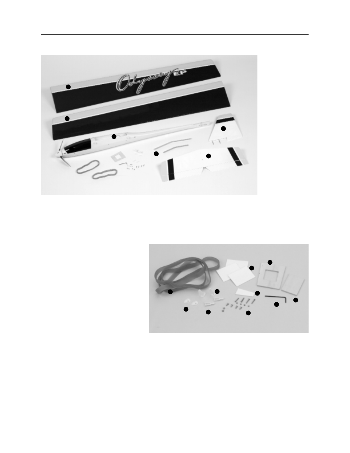
Main Parts
Other Parts
A. #64 Rubber bands (4)
B. Clevis (2)
C. Control horn plate (2)
D. Control horn (2)
E. Double sided tape
F. 2 mm control horn screws and nuts (4)
G. Micro switch mount
H. Allen wrench
I. Micro server adapter plate
J. Micro switch servo mount
6
Kit Contents
1. Left wing
2. Right wing
3. Horizontal stabilizer/elevator
4. Vertical stabilizer/rudder
5. Fuselage w/motor and wiring harness
6. Canopy
7. Wing joiners
1
2
3
4
5
7
6
A
B
C
D
E
I
J
F
G
H
Page 7
Parts Needed
• Right wing panel
• Left wing panel
• Aluminum wing joiners (Braces)
Tools and Adhesives Needed
• Scotch tape
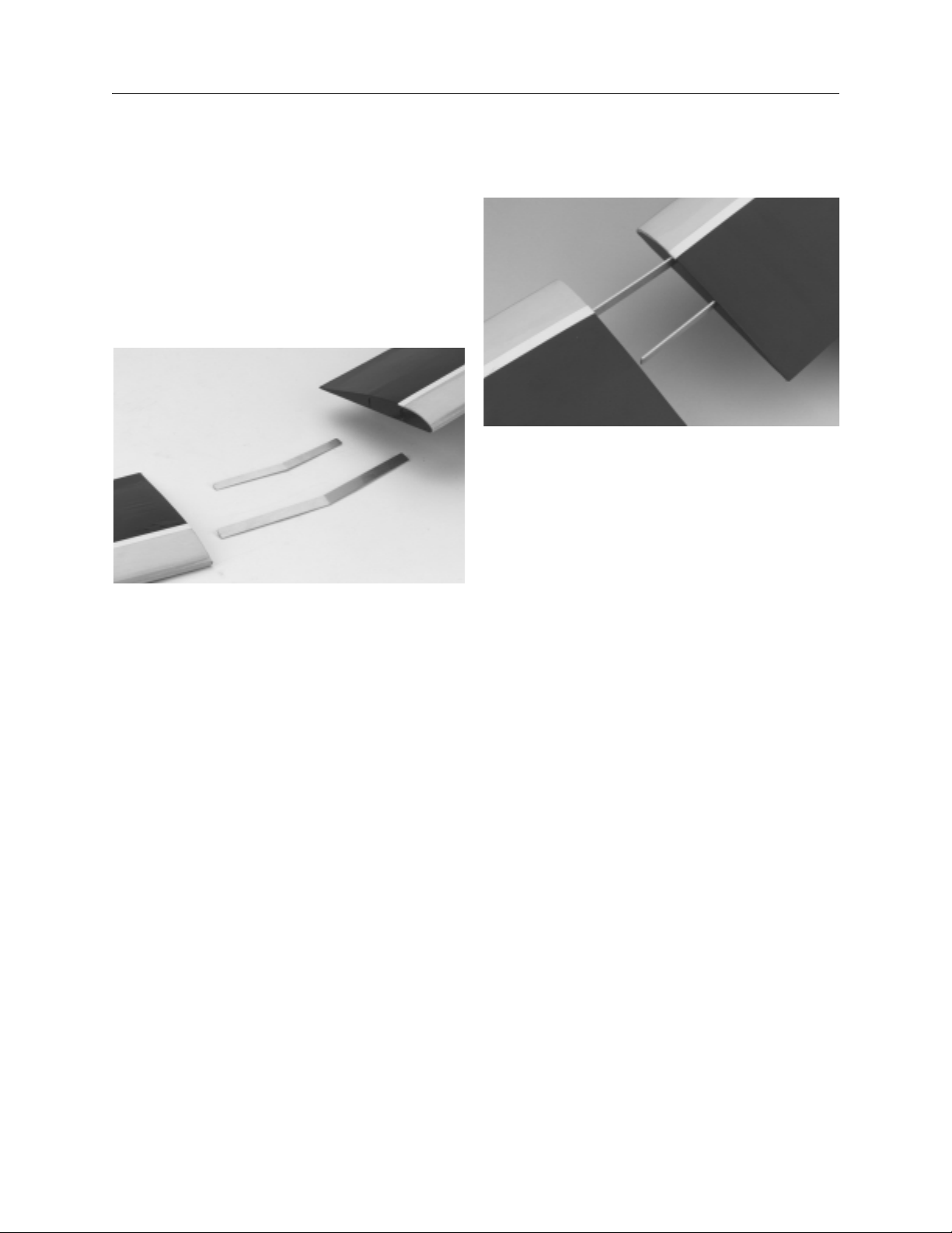
Step 1. Locate the two wing panels and aluminum
wing joiners.
Step 2. Trial fit the two wing joiners (dihedral braces) into one
of the wing halves. They should insert smoothly. Now slide the
other wing half onto the wing joiners until the wing halves meet.
Step 3. Tape the wing halves together using scotch tape. This
allows for easy breakdown of the wing for transportation.
7
Section 1: Joining the Wing
Page 8
Parts Needed
• Horizontal stabilizer with elevator attached
• Vertical stabilizer with rudder attached
• Nylon control horns (2)
• Nylon backplates (2)
• 2 mm screws (4)
• 2 mm nuts (4)
Tools and Adhesives Needed
• Medium Phillips screwdriver
• Felt-tipped Pen
• Drill Bit: 1/16"
• Drill
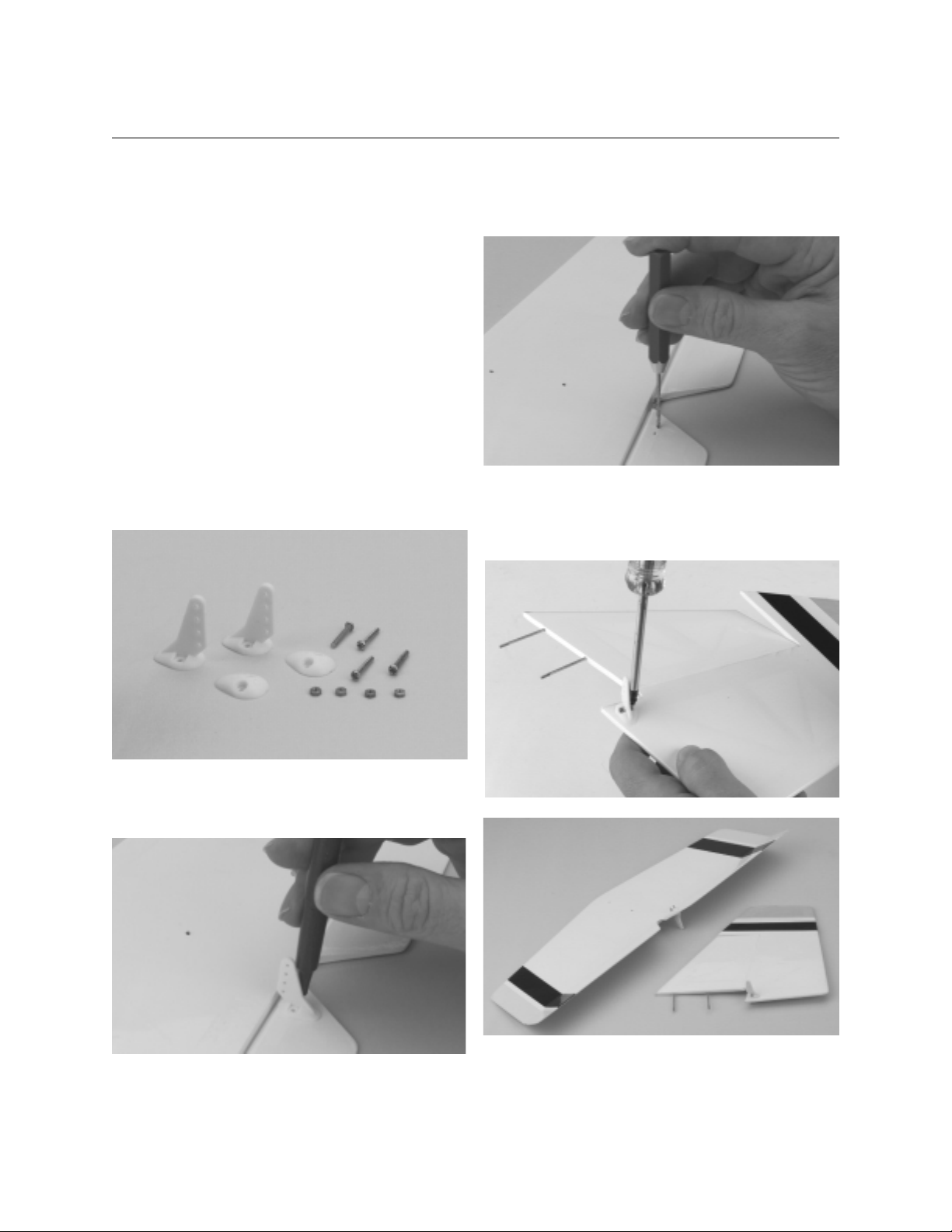
Step 1. You will attach the rudder and elevator control horns
next. Locate the two nylon control horns, the two backplates and
the four 2 mm control horn screws and nuts
Step 2. Install the elevator control horn first. It will be located
on the bottom of the elevator, as shown in the photo below.
Please note that the trim is located on top of the elevator.
Step 3.Mark the post where the horn will be placed using
a felt-tipped marker and drill the marked locations using a
1/16" drill bit.
Step 4. Mount the rudder control horn to the vertical fin/rudder
using the two screws and nuts provided. Mount the control horn
on the left side of the rudder using the same method as above.
8
Section 2: Installing Rudder and Elevator
Control horns
Page 9

9
Parts Needed
• Fuselage
• Horizontal stabilizer with elevator
• Vertical stabilizer with rudder
• Hardware package
Tools and Adhesives Needed
• Hobby knife
• Phillips screwdriver
• Blue Locktite
• Adjustable wrench
Caution: The 2 mm nuts used to mount the tail assembly to the
fuselage are small and easily lost. Use great care during that part
of the assembly so you do not inadvertly lose these parts.
Step 1. Locate the two white plastic clevises and screw them
onto the pushrods 10 turns at the rear of the fuselage. This will
prevent the pushrods from sliding out of the fuselage.
Note: The control surfaces, elevator and rudder are prehinged
using the covering applied to the tail structure. Check to make
sure the covering is secure. If necessary, a sealing iron can be
used to re-adhere the covering.
Step 2. Locate the horizontal stabilizer and elevator that will be
attached to the fuselage.
Step 3. Locate the vertical tail fin and rudder.
Step 4. Mount the vertical fin and rudder to the horizontal
stabilizer and elevator by sliding the two metal rods through the
holes in the horizontal stabilizer. Then push the rods through the
fuselage and lock them in place using an adjustable wrench the
two 2 mm nuts. Use blue Locktite on the threads to secure the
nuts in place.
Step 5. Attach the elevator and rudder clevises to the outter
most hole on the control horns. See page 15 for "Control Throw."
Section 3: Installing the Tail
Page 10

10
Parts Needed
• 3- or more-channel radio system with 3 standard servos and
hardware (not included)
• Radio packing foam (not included)
• Adapter plate if micro servos are used
Tools and Adhesives Needed
• Small Phillips screwdriver
• Hobby knife with #11 blade
• Pencil or felt-tipped pen
• Double-sided ser vo tape
• Velcro
®
Note: Velcro®tape is used for mounting the receiver and
battery pack.
Step 1. Install the grommets and eyelets in the three servos per
the instructions included with the radio.
Step 2. Locate the servo tray mounted in the fuselage.
Note: The rails have holes drilled for standard servos. If you
plan to use micro servos, use the plywood square to mount
them. Trial fit the two servos on the rails. Try to place each servo
close to the sides of the fuselage, as shown below. It's a good
idea to remove the two servo arms at this time to make it easier
to fit the servos in place
Step 3. Using a Phillips screwdriver, screw the eight screws to
secure the servos.
Step 4. Remove the servo arms from the servos if you have not
already done so. Only one arm of a servo arm will be used, the
other three will be trimmed off so the arms do not bind with the
side of the fuselage. Please refer to the photo below before trimming the arm. The elevator and motor control servos will utilize
the bottom arm as you look down at the servo arm; the rudder
will utilize the upper arm as you look down at the servo arm.
Trim off the other excess arms using a sharp hobby knife.
Step 5. Electronically center the servos and install the servo
arms.
Section 4: Installing the Radio
Page 11

11
Step 6. Attach the appropriate servo leads to the receiver. Use
Velcro
®
to mount the receiver and receiver battery to the bottom
of the fuselage compartment.
Step 7. The receiver antenna will be run from the opening in
the fuselage area out to the fuselage tail.
Step 8. Before mounting the motor battery pack into the fuselage tray, apply a strip of Velcro®to both the tray and the battery.
This will help to keep the battery in place. Balance of the
Odessey EP can be adjusted to some degree by moving the
motor battery pack back and forth on the fuselage tray. Always
try this first before adding any weight to the aircraft. Refer to
Section 9, "Balancing the Odessey EP," for more information.
Step 9. A micro On/Off switch and a single-pole/double-throw
switch are installed in the sides of the fuselage near the motor
and the radio compartment. The micro switch is to power the
receiver and the single pole/double throw switch is an "arming
switch." The arming switch prevents unwanted power from being
applied to the motor and prevents accidental startup. Remember
the propeller has sharp edges and can cause injury if you stick
your hand or fingers into it when it is operating.
Note: If you plan on using an electronic speed control, the
receiver battery will not be required, the motor battery will
provide power for the receiver, as well as the motor. Refer to the
manufacturer's operating instructions for proper hook up of an
electronic speed control.
Page 12

Step 10. The micro-switch is used to turn the motor on and off
in flight. Use double-sided servo tape to attach the micro-switch
to the side of the servo as shown below.
Step 11. A servo is used to activate the micro-switch through
the use of the servo arm. If you have not done so, trim three of
the four arms off of the servo arm, leaving the one that faces up
as you look down at the servo. You only need one of the arms to
activate the switch. Use double-sided tape to mount the servo to
the bottom of the provided plywood tray in such a position as to
allow the servo arm to depress (turns motor on) the switch when
the servo moves in one direction and release (turns the motor
off) the switch when the arm is moved in the opposite direction.
The motor should come on only when the micro switch is
depressed. The servo can be connected to the throttle servo so
that the micro-switch is activated when the throttle is full on.
Step 12. Attach the servo to the plywood servo mount plate
using double-sided servo tape. Apply another section of doublesided servo tape to the bottom of the mount plate to attach it into
the fuselage.
Step 13. Place the plywood plate with the micro switch/servo
into the area of the fuselage aft of the motor near the arming
switch position and attach with double-sided servo tape.
12
Page 13

13
Parts Needed
• Fuselage
• Pushrod , threaded on one end (1)
• Pushrod wire, threaded on one end (1)
• Clevis (2)
• Clevis keeper (used to keep clevis closed)
(2 pieces of fuel tubing 7mm long - not included)
Tools and Adhesives Needed
• Felt-tipped pen or pencil
• Hobby knife
• Masking tape
• Ruler
Step 1. Locate the control linkages for rudder and elevator that
are installed in the fuselage.
Step 2. Check to see that the clevis for the elevator and
rudder are attached and a clevis keeper (piece of fuel tubing)
is installed.
Step 3. Make sure the rudder and elevator servo arms are centered, and attach the metal pushrods to the respective servo
arms. The control linkage length can be adjusted by threading
the clevis at the control horn in or out.
Step 4. With the rudder and elevator pushrods attached, and the
micro switch/servo installed, check the function of the controls
by turning on the transmitter, then the receiver.
Caution: Be sure the throttle stick on your transmitter is at the
low-speed position. Use extreme care when first engaging the
throttle. Be sure the propeller is clear of any obstruction,
especially your hands or any part of your body.
Turn on the radio On/Off switch. Turn on the "Arming" switch.
Check the function of the rudder, elevator, and throttle controls.
Step 5. Make any necessary adjustments to control linkages, or
servo arm position to micro-switch so that the controls move
freely without any servo binding and that the motor turns on and
off. Also check to make sure the "Arming" switch functions properly by having the system on and running, and then turning off
the arming switch. The motor should stop.
Section 5: Installing the Control Linkages
Page 14

The control throws listed below are a good place to start. After
you have become more comfortable with the flight performance
of the Odyssey, you can adjust the control throws to satisfy your
style of flying.
Elevator: 3/8" UP3/8" Down
Rudder 1 3/4" Right 1 3/4" Left
Note: The control throw is measured at the point of the
control surface farthest from the hinge line. You can change
the control linkage attachment points in or out on the control
horns and/or servo arms to change the amount of throw on
each surface.
Parts Needed
• Fuselage
• Canopy
Step 1.Slide in rear canopy pin in pre-drilled hole in rear of the
canopy opening on the fuselage.
Step 2. Pull back the canopy lever on the top of the canopy and
place the canopy pin in the predrilled hole on the front of the
canopy area on the fuselage.
14
Section 7: Control Throw Recommendations
Section 6: Installing the Canopy
Page 15

15
Parts Needed
• Assembled Odyssey kit
Tools and Adhesives Needed
• Masking tape
• Pencil or pen
• Lead "Stick-on" weights (optional)
Step 1. The balancing of your Odyssey EP is an important step
that must not be omitted. The center of gravity (CG) of your
Odyssey EP should be 3 3/16" behind the leading edge of the
wing at the fuselage. Shift the motor battery fully forward to
balance the model if it is tail heavy or add weight to the nose.
If the model is nose heavy you can shift the position of the
receiver battery location in an attempt to balance the model, or
add weight to the tail (fuselage). Note that adding weight is the
last option.
Step 2. To balance the model, it should be fully assembled with
the radio and receiver battery installed and ready to fly. Place a
strip of masking tape on either side of the wings lower surface,
next to the fuselage.
Step 3. Mark the location of the CG on the bottom of the wing
either side of the fuselage.
Step 4. Pick up the plane from a level position using one finger
under the wing on each mark. Shift the battery location or add
lead weight until the plane remains level when you pick it up.
Section 8: Balancing the Odyssey
Page 16

A key component to soaring is the air mass the sailplane flies in.
Also, there is an energy source producing lift, either a warm air
thermal (thermal lift), or the wind rising as it meets an obstacle
such as a hill or a line of mountains (ridge lift). We will limit our
discussion to describing thermal soaring.
We will be using the electric motor to launch our sailplane to
altitude. Once at altitude we shut down the motor and the
sailplane will soar, eventually to return to earth until we use
the motor to climb again. How then does a sailplane stay aloft
for long periods of time and travel long distances? Some force
has to provide sufficient lift to overcome gravity when the
motor is not used.
One such force is the thermal. The thermal is simply a column
of rising warm air. Warm air is lighter (less dense) than cooler
air and thus rises. The term "differential heating" is used to
describe the generation of thermals. Descending cool air is
known as "sink."
The principle of warm vs cool air is used by balloonists to
launch and fly their hot air balloons. They create and trap warm
air inside the balloon envelope, and the warm air displaces the
cool air, causing the balloon to inflate and rise until air begins
to cool inside the envelope. The balloonist simply uses a
propane heater to warm the air again and the balloon rises again
or maintains its altitude.
Nature generates thermals by the sun heating darker ground or
objects more that lighter colored surfaces. The dark object
absorbs the sun's heat becoming warm and thus warming the
air above it.
For a thermal to be formed, the sun (or a heat source, such as a
hot metal roof, factory, etc.,) will heat the ground or surrounding
air in one location faster or warmer than the surrounding air. The
warm ground will warm the air above it and cause the air to
begin to rise. Rising warm air can take on the form of a column
or a funnel. Usually the part of the thermal near the ground is
small and expands outward as it rises in altitude.
Since the warming of air is usually a much smaller area than
the total area, the thermal updraft will be faster than the cooler
downdraft motion of air. This cooler downdraft of air is referred
to as "sink" and causes glider flights to be of a much shorter
duration as the lift generated by the wing is overcome by the
downward motion of the air.
To stay aloft one's task is to move from one thermal to another,
utilizing the lift created by rising warm air. In level flight, a glider
continuously descends in relation to the surrounding air. The
only way to sustain flight in a glider beyond the sink time in still
air (without a motor) is to fly in an air mass that is rising at a
rate greater than the sink rate of the glider.
Thermals usually cannot be seen. (An exception is a "dust
devil—a small thermal that has picked up dust making it
visible.) One can sometimes "feel" the presence of a thermal.
A breath of air in an otherwise calm spot indicates the presence
of a thermal. A shift in the wind (in a light breeze) probably indicates airflow into a thermal. And one can watch for the graceful
soaring of birds, such as hawks and eagles to locate the presence of thermals.
Sometimes the wind will cause the thermal to bend or break
causing a warm air bubble that slowly travels downwind as it
rises. Thermals can vary in strength, rising at speeds of a few
hundred to over a thousand feet per minute.
Thermal Forms (Column)
16
Section 9: Thermal Soaring
Page 17

17
Thermal Forms (Bubble)
As you are flying your Odyssey EP, watch it carefully. If you were
in a full-size glider, you would be able to feel the "bump" of
entering a thermal. Now you must depend on signs the glider
gives as it approaches or enters a thermal.
When the Odyssey flies near a thermal that is rising, the wing
closest to the thermal will also try to rise, causing the aircraft to
"rock" slightly. The nearness of a thermal will cause the glider to
"turn away" without any control input from the pilot.
There are several ways of entering a thermal. One is to continue
the thermal induced turn for 270 degrees. If the thermal is on
your left, turn right for 270 degrees and enter at a right angle to
the original flight path.
270° Turn Into a Thermal
The second method is to make a wide 180-degree turn back into
the thermal.
180° Turn Into a Thermal
Once in the thermal, you will need to try to stay in the center of
the lift. Slow down by increasing the up elevator "trim" until the
sailplane is just above a stall (minimum sink speed). Make easy
banking turns to find the area of highest lift (thermal core). When
you have found the core of lift, tighten the turns to stay within
the core of highest lift.
Flying in the Core of a Thermal
As you gain experience, you will find it easier to locate thermals
and track their progress.
Page 18

Step 1. Check that all control functions move in the correct
direction. If not, use the respective reversing switch to correct
the direction.
Step 2. Check that each clevis is securely snapped into
position. Be sure to use the clevis locking devices (small
pieces of tubing slipped over the clevis to hold the clevis
closed and prevent accidental opening in flight).
Step 3. Check that all servo horn screws are tight.
Step 4. Charge the transmitter and receiver batteries per the
instructions included with the radio system.
Step 5. Range check your radio system per the manufacturer's
instructions.
18
Elevator
Elevator
Section 10: Preflight Checks
Rudder
Rudder
Page 19

You will need to balance your Odyssey EP™after you've completed assembly and have installed the receiver, battery, and servos.
Use of the stick-on type of weights is recommended and can be
obtained at your dealer. Before adding weight to the sailplane, try
moving the battery pack to adjust the center of gravity (usually
as far forward as possible).
We strongly recommend that before you fly your new Odyssey
EP, you first perform a test glide. Pick a flat spot that has soft,
tall grass and is free from obstructions. You first want to check
out the Odyssey's performance but also check your performance
as a pilot. It also allows you to make corrections to any building
or control defects that may have been overlooked.
The test glide should be done with an assistant on a calm day.
Hint: A good time during the day is very early in the morning or
at dusk when the wind is calm. You want to be able to concentrate on what the model is doing, and have time to think about
what you're doing. We will assume you have an assistant during
the following steps.
Step 1. Range check your radio system and check the control
throws. Make sure the control surfaces move in the proper
direction.
Step 2. Have the assistant hold the Odyssey EP under the wing
near the CG and run forward until they can sense the wing developing lift. Don't release the glider yet. See if the model wants to
lift. If not, add a bit of up elevator trim and try again.
Step 3. This step may take some practice on the part of your
assistant. What you want them to do now is run forward, but a
bit faster, with the nose of the Odyssey EP pointed at the horizon
with the wings level (not nose down or nose up). Then thrust the
Odyssey EP forward in a line straight toward the horizon and
release it.
Step 4. When the assistant releases the model, watch it carefully.
A properly trimmed aircraft will fly straight forward gliding to a
smooth landing about 50 feet away. If the Odyssey EP pitches
nose down, the CG is too far back and you have a nose heavy
condition. Remove some weight from the nose. If the Odyssey
pitches nose up sharply, and stalls, you have a tail heavy condition (the CG is too far forward), and you need to remove weight
from the tail or move the battery and receiver further forward.
Step 5. Turns to the left or right after launch can be adjusted
through use of right or left rudder trim.
Important: Make any trim adjustments in small increments.
Large changes can result in abrupt turns resulting in tip stalls
and loss of control.
Step 6. If you have to make large trim adjustments on your
transmitter, you may have other problems, such as warps. Check
the wings, elevator, and rudder to make sure there are no warps
in the airframe. Make sure the wings are aligned or mounted
properly on the fuselage.
When you have the Odyssey EP trimmed and the CG adjusted so
it glides properly in a "hands-off" manner, return you transmitter
trim switches to their neutral position, then make the appropriate
mechanical linkage corrections to return the control surfaces to
their test glide positions.
Step 7. After you have made the necessary corrections, test
glide the model again to make sure it is trimmed properly with
the transmitter trims in neutral.
Step 8. You are now ready to launch under power. Apply power
and have your assistant run forwards as before. Gently throw the
Odyssey EP at a point on the horizon. Let the aircraft gain speed
before attempting to make any abrupt changes in direction.
Remember to make small control inputs, you do not want to stall
close to the ground. Use a slight bit of "up elevator and allow the
Odyssey EP to make a gentle climb to 200-300 feet. You can
then shut down the motor and go hunting for thermals.
19
Section 11: Test Glide
Page 20

20
Once the fundamentals of launch, trim, and control of the
Odyssey EP are learned, it's time to consider getting the most
out of the it's ability to perform. To do that, one must learn how
to trim the Odyssey for maximum performance, whatever the
current conditions are at the time.
The key to trimming the Odyssey EP for maximum performance
is to become knowledgeable of three key speeds: minimum sink,
maximum lift/drag (L/D), and best penetration. These three
speeds are what we call airspeeds, not ground speeds (the aircraft's speed across the ground). Thus the airspeed of the
Odyssey EP is relative to the air mass surrounding it.
To determine the Odyssey's airspeed, you will have to watch
carefully for its pitch atttitude. Pitch attitude can best be
described as the amount (degree) the nose of the aircraft is
above or below a line relative to the horizon. The angle of attack
term is used to describe the angle between the chord (width) of
the wing and the direction the wing moves through the air.
Pitch Attitude
Minimum Sink Speed
In our discussion of thermals, we know sink is the cooler
air moving downward to replace the warm air that is rising.
Minimum sink speed is the speed at which a sailplane loses
altitude most slowly. As the term then implies, minimum sink
speed gives the glider the maximum amount of time aloft from
a given altitude. This is the speed to fly at when you are circling
in thermals, or whenever you need the maximum lift the glider
can produce. The pitch attitude will appear to be more nose up.
To determine what this speed is for your Odyssey EP, you will
need to fly at a slow speed, slowing down until it just stalls,
then, trim it to fly at a speed just above where it begins to stall.
Observe the pitch attitude at this speed. You will need to practice
flying at this speed without stalling so you can come back to it
whenever you want to when you are in a thermal or trying to
maintain maximum lift.
Maximum Lift/Drag (L/D) Speed
This is the speed at which you can fly the maximum distance for
a given altitude. It's used when you move from one thermal to
another, or when you need to cover the maximum distance over
ground. This will be a moderately faster airspeed than the minimum sink speed. You will have to experiment by starting from
the minimum sink speed and add small amounts of down trim to
increase speed slightly. This is the speed the Odyssey performs
the best for duration, and the speed at which you will do most of
your flying. It will take practice until you are familiar with the
Odyssey's attitude at this speed. Remember you will be flying
slightly faster, at a lower pitch attitude as compared to minimum
sink speed.
Best Penetration Speed
This is the speed at which the Odyssey EP will travel forward
against the wind or a thermal, as far and as quickly as possible.
This speed will vary with the conditions, such as windy situations or very strong thermals. You will want to use this speed to
escape from very strong lift (or sink). This speed has a more
pronounced nose down appearance, which will vary with the
conditions encountered. It will also not be a consistent attitude,
but vary with the strength and direction of the lift/sink or wind.
Once you have learned to launch and control your Odyssey EP
in a consistent manner, you will want to then proceed with
practicing these three speeds. Remember these are trim speeds,
so you will be using your trim lever to obtain them. For maximum
performance, remember to use trim sparingly, don't depend on
the stick as you will only impart small movements that result in
drag and battery drain.
Practice smooth control inputs and use the trim lever.
(Remember you trimmed the Odyssey EP in the first flights, then
set the mechanical linkages to reflect the trim imparted. You then
set your trim levers back to neutral. Now you know why we performed that procedure, to allow you to use the trim lever for inflight trim to better control flight performance.)
There are other things that can be done to bring the performance
level of your Odyssey EP to its absolute best. However, they
should not be attempted until you have become proficient in the
launch, control, and trim of your model.
The more you learn how to trim your Odyssey EP for optimum
performance, the more fun you can have chasing thermals!
Section 12: In-Flight Adjustments for
Performance and Conditions
Horizon
Line Relative toHorizon
Pitch
Attitude
Longitudinal
Axis
Center of
Gravity
Nose
Page 21

21
Activating (Arming) Switch: an external switch that prevents
the electric motor from accidentally turning on
Aerodynamics: science of air in motion
Angle of Attack (AOA): angle between the chord of the wing
and the relative wind that strikes the airfoil; independent of the
attitude of the sailplane with respect to the horizon
Auto-Peak: type of battery charger that automatically shuts off
when a battery has been fully charged
Axis: a line passing through a body about which the body
revolves
Battery Cycling: repeated charge and discharge of a battery to
erase battery memory
Battery Memory: term used to explain why a batter y is unable
to take on a full charge because of insufficient discharging
before recharging
Capacity: amount of charge or electricity a battery can hold
Center of Gravity (CG): balancing point of an aircraft
Critical Angle of Attack: angle of attack at which smooth airflow
over the top of the wing stops
Electrolyte: a caustic material found in batteries
Harness: a device consisting of wires, switches, and a fuse that
connects the motor to the battery
L/D: lift divided by drag expressed as a ratio; the same as a
glide ratio (think of L/D as a glide slope, then, for a given
amount of distance, the sailplane moves forward it drops a
certain amount.)
Minimum Sink: the speed at which a sailplane loses altitude
most slowly, expressed in feet per minute
Ni-Cd (Nickel Cadium) Battery: a rechargeable battery used
for radio control airplanes
Penetrate: to make progress against the wind
Pitch: degree of nose up or nose down from level to the horizon
Relative Wind: direction that the air molecules strike the
leading edge of the wing
SCR: a battery designed to release a lot of energy over a short
time without being damaged
Span: the maximum distance from wingtip to wingtip
Stall: loss of lift resulting from exceeding the critical angle of
attack
Thermal: rising body of hot air that can take a sailplane to a
great height
Section 13: Definitions
Page 22

22
GENERAL
1. I will not fly my model aircraft in sanctioned events, air
shows, or model flying demonstrations until it has been proven
to be airworthy by having been successfully flight tested.
2. I will not fly my model higher than approximately 400 feet
within 3 miles of an airport without notifying the airport operator.
I will give right-of-way and avoid flying in the proximity of fullscale aircraft. Where necessary, an observer shall be utilized to
supervise flying to avoid having models fly in the proximity of
full-scale aircraft.
3. Where established, I will abide by the safety rules for the
flying site I use, and I will not willfully and deliberately fly my
models in a careless, reckless and/or dangerous manner.
4. At all flying sites a straight or curved line(s) must be
established in front of which all flying takes place with the other
side for spectators. Only personnel involved with flying the aircraft are allowed in front of the flight line. Flying over the spectator side of the lines is prohibited, unless beyond the control of
the pilot(s). In any case, the maximum permissible takeoff weight
of the models with fuel is 55 pounds.
5. At air shows or model flying demonstrations a single straight
line must be established, one side of which is for flying, with the
other side for spectators. Only those persons accredited by the
contest director or other appropriate official as necessary for
flight operations or as having duties or functions relating to the
conduct of the show or demonstration are to be permitted on the
flying side of the line. The only exceptions which may be
permitted to the single straight line requirements, under special
circumstances involving consideration of site conditions and
model size, weight, speed, and power, must be jointly approved
by the AMA president and the executive director.
6. Under all circumstances, if my model weighs over 20 pounds,
I will fly it in accordance with paragraph 5 of this section of the
AMA Safety Code.
7. I will not fly my model unless it is identified with my name
and address or AMA number, on or in the model. This does not
apply to models while being flown indoors.
8. I will not operate models with metal-bladed propellers or with
gaseous boosts, in which gases other than air enter their internal
combustion engine(s); nor will I operate models with extremely
hazardous fuels such as those containing tetranitromethane or
hydrazine.
9. I will not operate models with pyrotechnics (any device that
explodes, burns, or propels a projectile of any kind) including,
but not limited to, rockets, explosive bombs dropped from models, smoke bombs, all explosive gases (such as hydrogen-filled
balloons), ground mounted devices launching a projectile. The
only exceptions permitted are rockets flown in accordance with
the National Model rocketry Safety Code or those permanently
attached (as per JATO use); also those items authorized for Air
Show Team use as defined by AST Advisory committee (document available from AMA HQ). In any case, models using rocked
motors as a primary means of propulsion are limited to a maximum weight of 3.3 pounds and a G series motor. A model aircraft is defined as an aircraft with or without engine, not able to
carry a human being.
10. I will not operate any turbo jet engine (axial or centrifugal
flow) unless I have obtained a special waiver for such specific
operations from the AMA President and Executive Director and I
will abide by any restriction(s) imposed for such operation by
them. (This does not apply to ducted fan models using piston
engines or electric motors.)
11. I will not consume alcoholic beverages prior to, nor during,
participation in any model operations.
RADIO CONTROL
1. I will have completed a successful radio equipment ground
range check before the first flight of a new or repaired model.
2. I will not fly my model aircraft in the presence of spectators
until I become a qualified flyer, unless assisted by an experienced helper.
3. I will perform my initial turn after takeoff away from the pit or
spectator areas, and I will not thereafter fly over pit or spectator
areas, unless beyond my control.
4. I will operate my model using only radio control frequencies
currently allowed by the Federal Communications Commission.
(Only properly licensed Amateurs are authorized to operate
equipment on Amateur Band frequencies.)
5. I will not knowingly operate an R/C system within 3 miles of a
pre-existing model club-flying site without a frequency sharing
agreement with that club.
6. Models flown in air-to-air combat are limited to maximum
total engine displacement of .30 cu. in. and a maximum of dry
weight prior to flying of 4 pounds.
AMA Safety Code
2001 OFFICIAL AMA NATIONAL MODEL AIRCRAFT SAFETY CODE
Effective January 1, 2001
Model flying must be in accordance with this code in order for AMA Liability Protection to apply.
Page 23

23
ORGANIZED RC RACING EVENT
7. An RC racing event, whether or not an AMA Rule Book
event, is one in which model aircraft compete in flight over a
prescribed course with the objective of finishing the course faster
to determine the winner.
A. In every organized racing event in which contestants, callers
and officials are on the course:
1. All officials, callers and contestants must properly wear
helmets, which are OSHA, DOT, ANSI, SNELL, or NOCSAE
approved or comparable standard while on the racecourse.
2. All officials will be off the course except for the starter and
his/her assistant.
3. "On the course" is defined to mean any area beyond the
pilot/staging area where actual flying takes place.
B. I will not fly my model aircraft in any organized racing event,
which does not comply with paragraph A above or which allows
models over 20 pounds unless that competition event is AMA
sanctioned.
Refer to AMA Membership Manual 2001 for safety codes for
Free Flight and Control Line Models. Separate code(s) available
from AMA Headquarters for boats, cars, and rockets.
Academy of Model Aeronautics
5161 East Memorial Drive
Muncie, Indiana 47302-9252
Page 24

© Copyright 2001, Horizon Hobby, Inc.
(217) 355-9511
www.horizonhobby.com
Page 25

25
 Loading...