

Page 1
Advance 25e ARF
Assembly Manual
Page 2

Notice
All instructions, warranties and other collateral
documents are subject to change at the sole
discretion of Horizon Hobby, Inc. For up-to-date
product literature, visit http://www.horizonhobby.
com and click on the support tab for this product.
Meaning of Special Language
The following terms are used throughout the product
literature to indicate various levels of potential harm
when operating this product:
NOTICE: Procedures, which if not properly followed,
create a possibility of physical property damage
AND a little or no possibility of injury.
CAUTION: Procedures, which if not properly followed,
create the probability of physical property damage
AND a possibility of serious injury.
WARNING: Procedures, which if not properly followed,
create the probability of property damage, collateral
damage, and serious injury OR create a high
probability of superficial injury.
WARNING: Read the ENTIRE instruction
manual to become familiar with the features of the
product before operating. Failure to operate the
product correctly can result in damage to the
product, personal property and cause serious injury.
This is a sophisticated hobby product and NOT a
toy. It must be operated with caution and common
sense and requires some basic mechanical
ability. Failure to operate this Product in a safe
and responsible manner could result in injury or
damage to the product or other property. This
product is not intended for use by children without
direct adult supervision. Do not attempt disassembly,
use with incompatible components or augment
product in any way without the approval of Horizon
Hobby, Inc. This manual contains instructions for
safety, operation and maintenance. It is essential to
read and follow all the instructions and warnings
in the manual, prior to assembly, setup or use, in
order to operate correctly and avoid damage or
serious injury.
Warnings
Read and follow all instructions and safety precautions
before use. Improper use can result in fire, serious
injury and damage to property.
Age Recommendation: Not for children under 14
years. This is not a toy.
COMPONENTS
Use only with compatible components. Should any
compatibility questions exist please refer to the product
instructions, the component instructions or contact
Horizon Hobby, Inc.
FLIGHT
Fly only in open areas to ensure safety. It is
recommended flying be done at AMA (Academy of
Model Aeronautics) approved flying sites. Consult local
laws and ordinances before choosing a location to fly
your aircraft.
PROPELLER
Keep loose items that can get entangled in the
propeller away from the prop, including loose clothing,
or other objects such as pencils and screwdrivers.
Especially keep your hands away from the propeller as
injury can occur.
BATTERIES
Notes on Lithium Polymer Batteries
When misused, lithium polymer batteries are
significantly more volatile than alkaline or Ni-Cd/
Ni-MH batteries used in RC applications. Always
follow the manufacturer’s instructions when using and
disposing of any batteries. Mishandling of Li-Po batteries
can result in fire causing serious injury and damage.
SMALL PARTS
This kit includes small parts and should not be left
unattended near children as choking and serious injury
could result.
SAFETY PRECAUTIONS
• Checkallcontrolsurfacespriortoeachtakeoff.
• Donotflyyourmodelnearspectators,parkingareas
or any other area that could result in injury to people
or damage of property.
• Donotflyduringadverseweatherconditions.Poor
visibility can cause disorientation and loss of control
of your aircraft. Strong winds can cause similar
problems.
• Donottakechances.Ifatanytimeduringflightyou
observe any erratic or abnormal operation, land
immediately and do not resume flight until the cause
of the problem has been ascertained and corrected.
Safety can never be taken lightly.
• Donotflynearpowerlines.
2 E-flite Advance 25e ARF Assembly Manual
Page 3

Table of Contents
Introduction
Using the Manual
Notice ......................................................................2
Meaning of Special Language ...................................2
Warnings .................................................................2
Introduction .............................................................. 3
Important Information Regarding
Warranty Information .......................................3
Specifications ...........................................................3
Using the Manual .....................................................3
Contents of Kit/Parts Layout ......................................3
Covering Colors ........................................................3
Hardware/Accessory Sizes ....................................... 3
Recommended Radio Equipment ................................4
Power 25 Motor Setup .............................................. 4
Power 32 Motor Setup .............................................. 4
Optional Accessories ................................................4
Required Tools and Adhesives ...................................4
Hinging the Ailerons .................................................4
Aileron Servo Installation ..........................................6
Joining the Wing Panels ............................................9
Radio Installation .................................................... 11
Nose Gear Installation ............................................13
Motor Installation .................................................... 15
Main Landing Gear Installation ...............................18
Wing Installation ....................................................20
Stabilizer and Vertical Fin Installation .......................21
Hinging the Elevator and Rudder .............................24
Rudder and Elevator Linkage Installation .................. 25
Optional Pilot Installation......................................... 27
Canopy Installation ................................................. 28
Canopy Installation ................................................. 29
Decal Installation ....................................................29
Center of Gravity .................................................... 30
Control Throws .......................................................30
Preflight ..................................................................31
Flying Your Advance 25e ARF .................................31
Range Test Your Radio .............................................32
Daily Flight Checks ................................................. 32
Warranty and Repair Policy .................................... 32
Warranty Services ..................................................33
Compliance Information for the European Union ...... 34
2010 Official Academy of
Model Aeronautics Safety Code ...................... 34
E-flite® is proud to announce the Advance 25e, a
low-wing sport plane with exceptionally smooth
flight performance at an accessible price. Designed
by world-class competition pilot and designer, Mike
McConville, this aircraft includes semi-symmetrical
airfoil wings for great aerobatic flight, tricycle landing
gear for excellent ground handling, and an UltraCote®
trim scheme to provide the best finish. Additionally,
convenience plays a big factor in the Advance 25e,
which is why it is designed for both 25 and 32-size
brushless outrunner motors and is constructed with a
bolt-on wing for simpler setup and tear-down for easy
transport.
Important Information
Regarding Warranty Information
Please read our Warranty and Liability Limitations
section before building this product. If you as the
Purchaser or user are not prepared to accept the
liability associated with the use of this Product, you are
advised to return this Product immediately in new and
unused condition to the place of purchase.
Specifications
Wingspan: 52.5 in (1335mm)
Wing Area: 535 sq in (34.5 sq dm)
Length: 49.0 in (1245mm)
Weight w/o Battery: 3.70–3.90 lb (1.6–1.8 kg)
Weight with Battery: 4.40–4.06 lb (1.9–2.1 kg)
This manual is divided into sections to help make
assembly easier to understand, and to provide breaks
between each major section. In addition, check boxes
have been placed next to each step to keep track
of its completion. Steps with a single circle () are
performed once, while steps with two or more circles
() indicate the step will require repeating, such as
for a right or left wing panel, two servos, etc.
Remember to take your time and follow the directions.
Contents of Kit/Parts Layout
Replacement Parts
EFL422501 Wing Set with Ailerons
EFL422502 Fuselage with Hatch
EFL422503 Tail Set
EFL422504 Pushrod Set
EFL422505 Landing Gear Set
EFL422506 Canopy
EFL422507 Decal Set
EFL422508 Wood Spacer, Power 32
EFL422509 Wheels Set
Covering Colors
White HANU870
True Red HANU866
Deep Blue HANU873
Hardware/Accessory Sizes
Main wheel diameter 21/4-in (57mm)
Nose wheel diameter 2-in (51mm)
3E-flite Advance 25e ARF Assembly Manual
Page 4
Recommended Radio Equipment
Optional Accessories
Hinging the Ailerons
You will need a minimum 4-channel transmitter,
receiver and six servos. You can choose to purchase
a complete radio system. If you are using an
existing transmitter, just purchase the other required
equipment separately. We recommend the crystalfree, interference-free Spektrum™ DX6 2.4GHz DSM®
6-channel system. If using your own transmitter, we
recommend the following radio equipment.
If you own the Spektrum DX6i radio, or you are using
a different DSM2 radio, just add the AR6200 DSM2
6-channel receiver and four JR SPORT™ MN48 servos.
Complete Radio System
SPM6600 DX6i DSM2 6CH system
Or Purchase Separately
SPMAR6200 AR6200 DSM2 6-Channel
Full-Range Receiver
JSP20040 MN48 Servo (4)
JRPA135 Y-harness ailerons to receiver
JSP98100 3-inch (76mm) Servo Extension
Power 25 Motor Setup
EFLM4025A Power 25 BL Outrunner
Motor, 870Kv
EFLA1040L 40-Amp Lite Pro SB
Brushless ESC
EFLB32003S30 3200mAh 3S 14.8V 30C Li-Po,
12AWG EC3
APC12080E 12 x 8E Electric Propeller
Power 32 Motor Setup
EFLM4032A Power 32 Brushless Outrunner
Motor, 770Kv
EFLA1060 60-Amp Pro Switch-Mode BEC
Brushless ESC
EFLB32004S30 3200mAh 4S 14.8V 30C Li-Po,
12AWG EC3
APC12060E 12 x 6E Electric Propeller
EFLSP175 13/4-inch Aluminum Spinner
EFLA110 Power Meter
EFLC505 Intelligent 1- to 5-Cell
EFLAEC312 Charge Lead with 12-inch
EFLA151 1/9 Civilian Pilot, Blue
Required Tools and Adhesives
™
Tools & Equipment
Drill Epoxy brush
Felt-tipped pen Flat file
Low-tack tape Mixing cup
Mixing stick Medium grit sandpaper
Paper towel Pencil
Pin vise Phillips screwdriver: #1, #2
Pliers Rubbing alcohol
Ruler Scissors
Side cutter Spinner
Square T-pins
Drill bit: 1/16-inch (1.5mm), 5/64-inch (2mm)
Hex wrench: 2.5mm, 3/32-inch
Hobby knife with #11 blade
Optional Tools & Equipment
Balancing stand (optional)
Box wrench: 10mm
Z-bend pliers
Adhesives
30-minute epoxy Silicone adhesive
Thin CA Medium CA
Threadlock
During the course of building your model we
suggest you use a soft base for the building surface.
Such things as a foam stand, large piece of
bedding foam or a thick bath towel will work well
and help protect the model from damage during
assembly. This is not shown in the instructions
to provide the greatest detail in the photos.
with 4mm and 5mm Collets
Balancing Charger
Wire and Jacks, 16AWG
Required Parts
Wing panel with aileron (left and right)
Required Tools and Adhesives
Thin CA T-pins
Pin vise Drill bit: 1/16-inch (1.5mm)
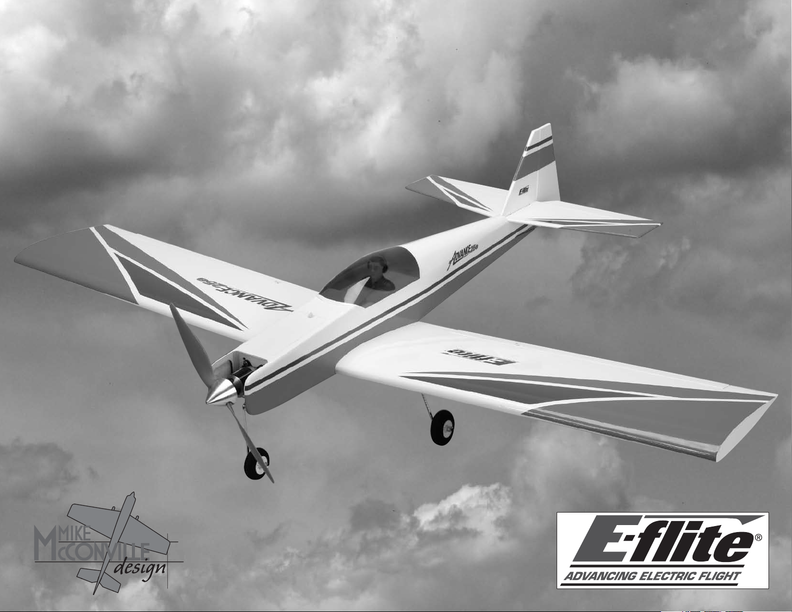
1. Locate the wing panel. Separate the aileron from
the wing panel. Set the four hinges aside at this time.
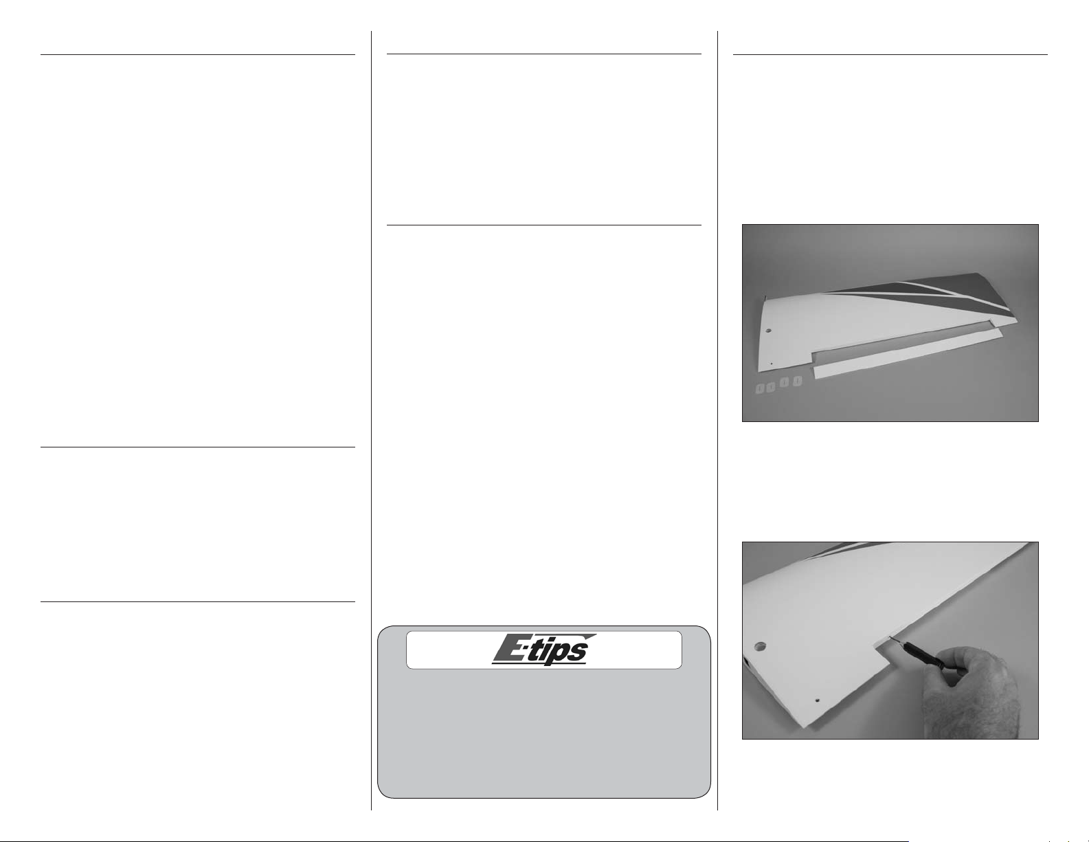
2. Use a pin vise and 1/16-inch (1.5mm) drill bit
to drill a hole in the center of each hinge slot in the
wing panel. This will provide a tunnel for the CA to
wick into, making the bond between the hinge and
wood stronger.
4 E-flite Advance 25e ARF Assembly Manual
Page 5
3. Prepare the aileron for hinging following the
procedure described in Step 2.
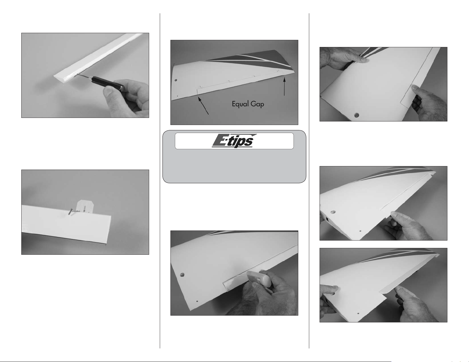
5. Slide the hinges in the aileron into the slots on
the wing. Check that the gap at each end of the
aileron is equal.
7. Once the CA has fully cured, gently pull on the
wing and aileron to make sure the hinges are glued
securely. If not, reapply thin CA to any hinges that
are not secure.
4. Slide the hinges into the aileron. Insert the
hinges so the holes in the hinge are at the hinge
line. Insert a T-pin through one of the holes to keep
the hinge centered when the aileron is installed on
the wing panel.
When gluing the hinges, do not use a CA
accelerator. The CA must be allowed time to
soak into the hinges to provide the best bond
between the hinge and surrounding wood.
6. Remove the T-pins from the hinges. Make sure
the aileron is tight against the wing. Wick thin CA
into each hinge, both top and bottom, until the
hinge is saturated with CA. Allow the CA to fully
cure before proceeding.
8. Flex the aileron through its range of motion
a number of times to break in the hinges. This
will reduce the initial load on the servo for your
first flights.
9. Repeat Steps 1 through 8 to install the remaining
aileron and hinges.
5E-flite Advance 25e ARF Assembly Manual
Page 6
Aileron Servo Installation
Required Parts
Silicone tubing Nylon clevis (2)
Transmitter Receiver
Wing panel with aileron (left and right)
Servo with hardware (2)
Threaded pushrod, 117/8-inch (302mm)
Nylon control horn with backplate (2)
2mm x 12mm machine screw (4)
Required Tools and Adhesives
Thin CA Pin vise
Side cutter Square
Felt-tipped pen Hobby knife with #11 blade
Ruler Low-tack tape
Pliers
Drill bit: 5/64-inch
Phillips screwdriver: #1
Optional Tools
Z-bend pliers
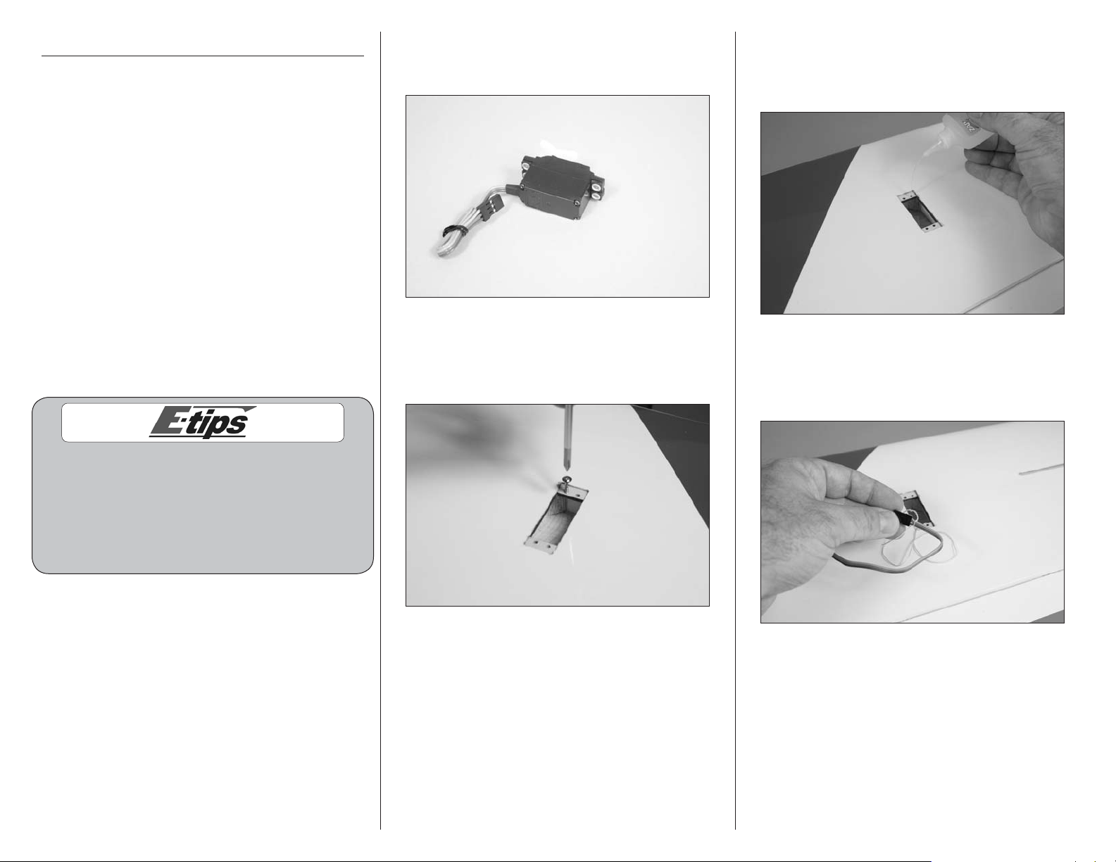
1. Prepare the aileron servo by installing the rubber
grommets and brass eyelets as described in the
servo instructions.
2. Use a #1 Phillips screwdriver to thread a
servo mounting screw in each of the four servo
mounting holes. This will cut threads into the
surrounding wood.
3. Apply 2–3 drops of thin CA in each of the servo
mounting holes. This will harden the threads in
the surrounding wood, which will help prevent the
screws from vibrating loose.
4. Carefully remove the string from the servo
pocket. Make sure not to pull the string loose from
the center of the wing. Tie the end of the string
around the servo lead near the connector.
Before starting the installation of the servos, it is
recommended to center the trims and sticks on your
transmitter. If you are using a computer radio, make
sure to reset a model memory and name it for this
particular model. We also recommend binding the
transmitter and receiver at this time following the
instructions provided with your radio system.
6 E-flite Advance 25e ARF Assembly Manual
Page 7
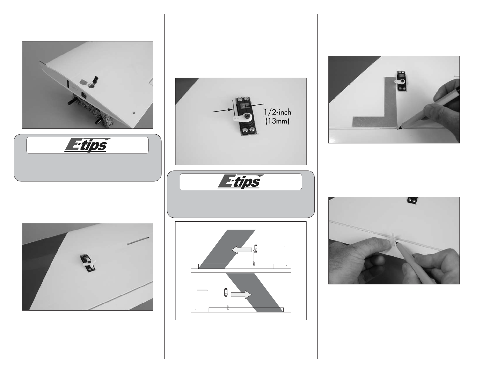
5. Use the string to pull the servo lead through
Toward Wing Tip
Toward Wing Tip
the wing and out of the hole in the top of the
wing panel.
7. Use the radio system to center the aileron servo.
Position the servo horn parallel to the hinge line
of the aileron. Enlarge the hole in the servo horn
facing toward the wing tip that is 1/2-inch (13mm)
from the center of the horn using a pin vise and
5/64-inch drill bit. Use side cutters to remove any
unused arms from the servo horn so they don’t
interfere with the operation of the aileron servo.
8. Position a square so it is aligned with the edge of
the wing and the hole in the servo horn enlarged in
Step 6. Use a felt-tipped pen to mark the aileron for
the aileron control horn. This aligns the horn and
linkage correctly for your model.
Leave a small amount of string tied to the servo lead.
Tape the string to the top of the wing to prevent
the servo lead from falling back into the wing.
6. Use the screws provided with the servo to secure
it in the wing. The output shaft of the servo will face
the aileron. Use a #1 Phillips screwdriver to tighten
the servo mounting screws.
9. Position the control horn on the aileron. The holes
in the control horn will align with the hinge line of
the aileron, and with the mark made in the previous
step. Use a felt-tipped pen to transfer the locations
for the control horn mounting screws on the aileron.
When installing the aileron servos, the
linkages must connect to the side of the
servo facing the wing tips as shown.
7E-flite Advance 25e ARF Assembly Manual
Page 8
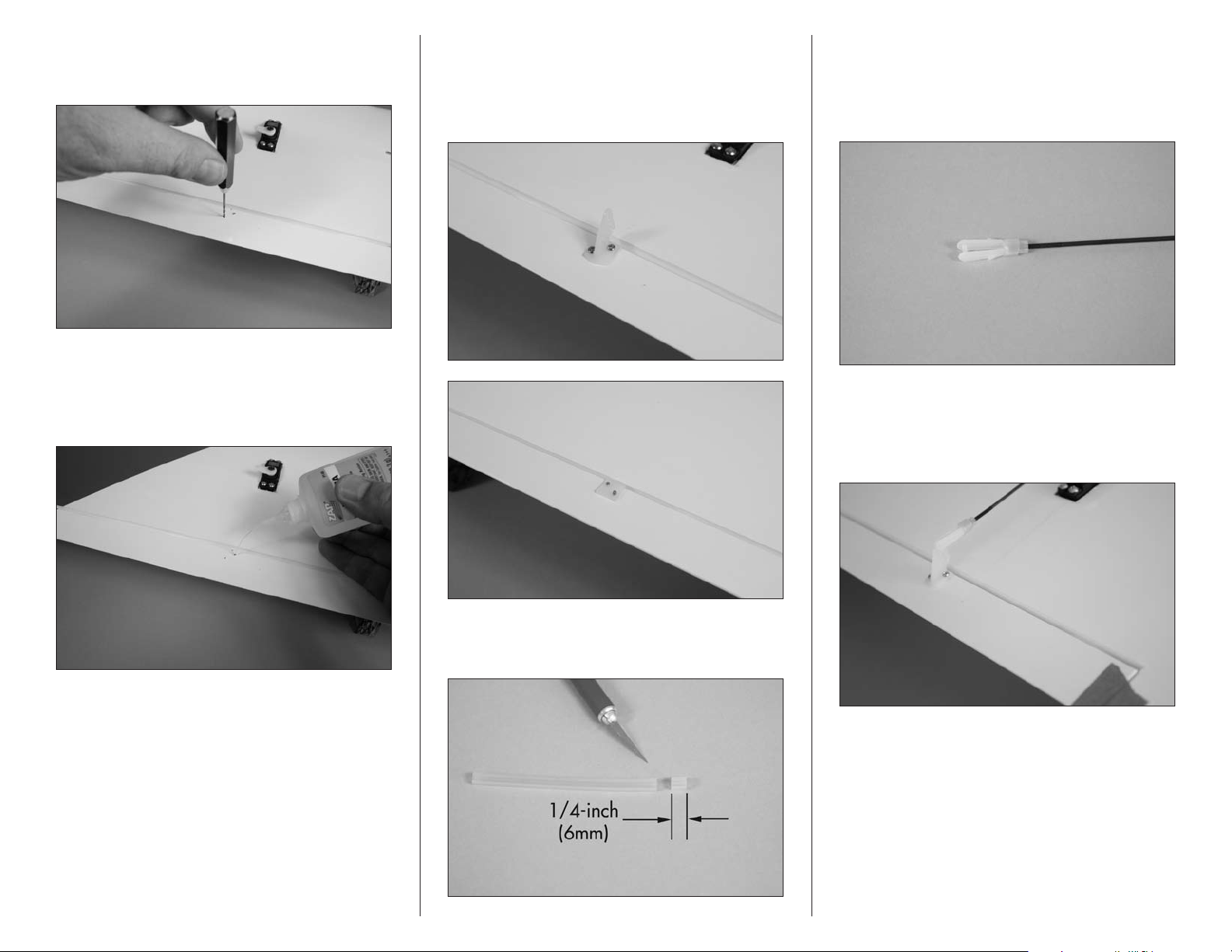
10. Use a pin vise and 5/64-inch (2mm) drill
bit to drill the two holes for the control horn
mounting screws.
11. Apply 2–3 drops on thin CA in each of the
holes to harden the surrounding wood. This will keep
the control horn secure and prevent the surrounding
wood from becoming damaged over time.
12. Attach the control horn to the aileron using two
2mm x 12mm machine screws and the control horn
backplate. Use a #1 Phillips screwdriver to tighten
the screws. Make sure not to over-tighten the screws
and damage the underlying wood.
14. Slide the small piece of tubing in a nylon clevis.
Thread the clevis 12-turns on a 117/8-inch (302mm)
threaded pushrod wire. This will provide enough
threads in the clevis to be secure and allow for
adjustment of the linkage.
15. Wrap a small piece of low-tack tape around
the aileron and trailing edge to keep the aileron
centered. Attach the clevis to the outer hole of the
control horn.
13. Use a hobby knife with a #11 blade to cut a
1/4-inch (6mm) piece from the silicone tube.
8 E-flite Advance 25e ARF Assembly Manual
Page 9
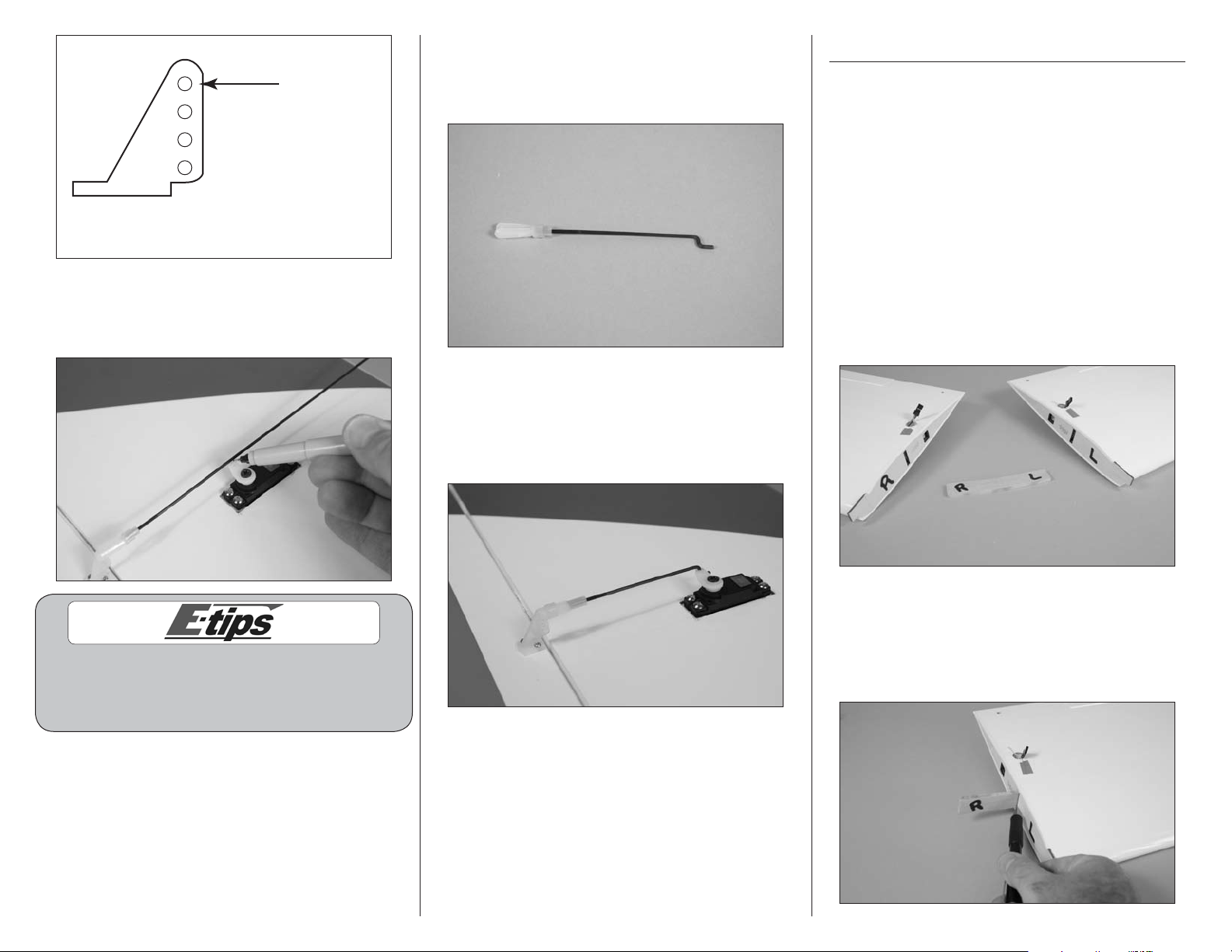
Drawing not to scale
Attach clevis
to outer hole
17. Disconnect the clevis from the control horn.
Make a Z-bend in the pushrod wire using a pair
of pliers. Use side cutters to trim the excess wire to
match the photo below.
Joining the Wing Panels
Required Parts
Wing panel with aileron (left and right)
Hardwood wing joiner
Required Tools and Adhesives
30-minute epoxy Pencil
Low-tack tape Paper towel
Mixing stick Mixing cup
Epoxy brush Rubbing alcohol
Medium grit sandpaper
16. Use a felt-tipped pen to mark the pushrod
where it crosses the hole in the servo horn that was
enlarged in Step 6.
Making a Z-bend takes some skill. There is
plenty of excess wire to experiment with. We
recommend using Z-bend pliers (HAN119) to
make the perfect Z-bend in your pushrod wire.
1. Locate the hardwood wing joiner. Mark the joiner
and wing panels with an “R” and “L” so the joiner
can be associated with a particular wing panel for
test fitting.
18. Insert the bend in the hole of the servo
horn. Reconnect the clevis to the outer hole of
the control horn. Slide the silicone tube over
the forks of the clevis to prevent it from opening
accidentally in flight.
2. Slide the wing joiner into one of the wing panels.
Use a pencil to draw a line on the joiner against the
wing as shown. The joiner should easily slide into
the wing panel. If not, use medium grit sandpaper
to lightly sand the joiner so it slides in easily.
19. Repeat Steps 1 through 19 to install the
remaining aileron servo and linkage. Remove the
low-tack tape securing the aileron before joining the
wing panels.
9E-flite Advance 25e ARF Assembly Manual
Page 10
3. Slide the joiner into the opposite wing panel.
It should slide in up to or past the line drawn in
the previous step. If not, you will need to sand the
joiner using medium grit sandpaper so it fits.
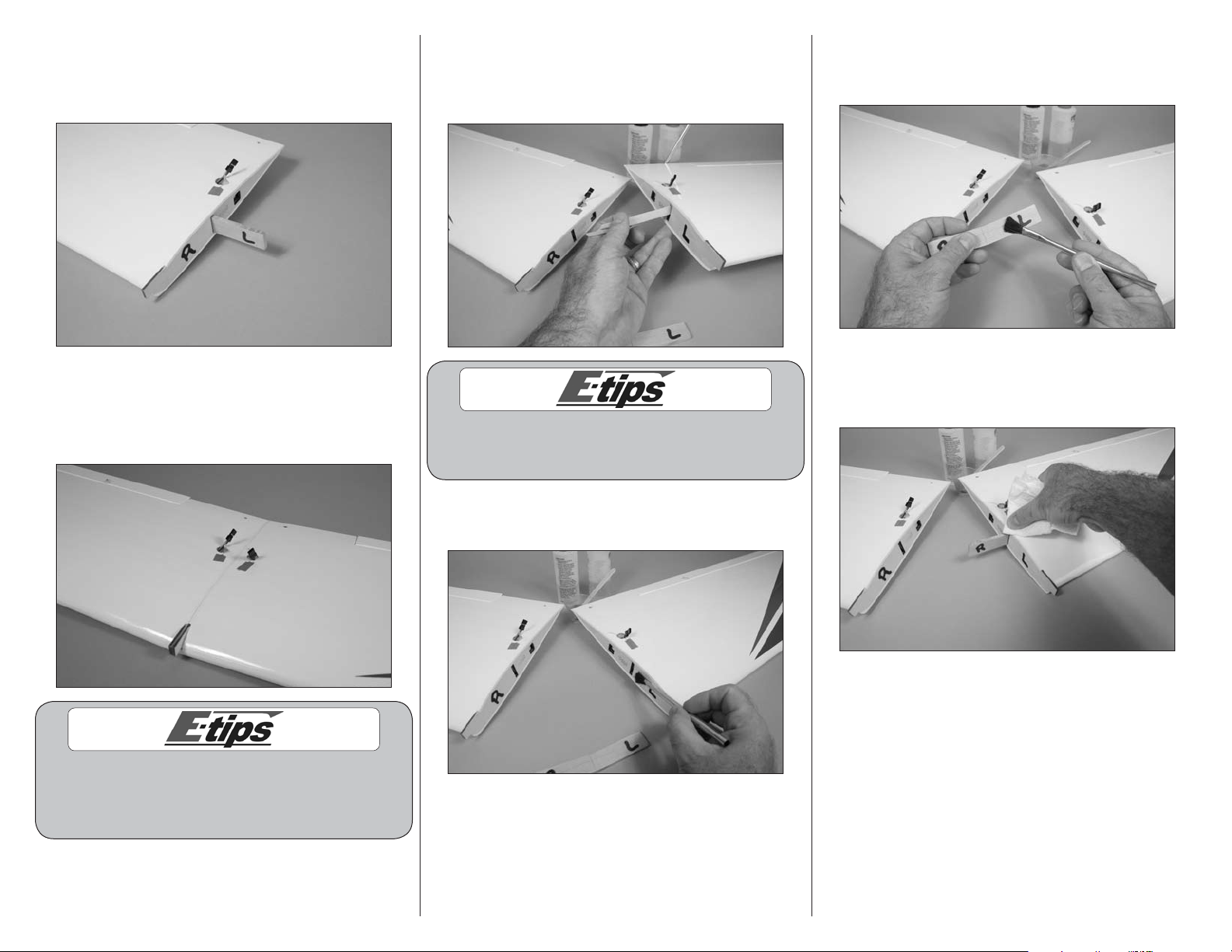
4. Slide the two wing panels together. They should
fit together tightly with no gaps. If there are
gaps, use medium grit sandpaper to make any
necessary adjustments.
5. Separate the wing panels and remove the joiner.
Mix 1/2 ounce (15mL) of 30-minute epoxy. Use a
mixing stick to apply epoxy into the joiner pocket of
one of the wing panels.
Before applying epoxy, wrap low-tack tape 1/32inch (1mm) from the root edge of the wing to help
prevent the epoxy from running onto the wing.
7. Use an epoxy brush to apply the epoxy to one
half of the joiner. Make sure to coat the front, back,
top and bottom of the joiner with epoxy.
8. Slide the wing joiner into the wing panel. Use
a paper towel and rubbing alcohol to remove any
excess epoxy.
6. Use an epoxy brush to apply a thin coat of epoxy
to the exposed wood on the wing root as shown.
The following steps must be completed
before the epoxy begins to cure. Make
sure to read through and understand the
following steps before mixing any epoxy.
10 E-flite Advance 25e ARF Assembly Manual
Page 11
9. Repeat Steps 5 through 8 to apply epoxy to the
exposed joiner and to the remaining wing panel.
Slide the panels together and use low-tack tape to
hold them tightly together until the epoxy fully cures.
Make sure to use a paper towel and rubbing alcohol
to remove any excess epoxy before it begins to cure.
10. Once the epoxy has fully cured, remove the
tape from the wing.
Radio Installation
Required Parts
Fuselage Servo with hardware (2)
Transmitter Receiver
Y-harness Hook and loop tape
Required Tools and Adhesives
Scissors Phillips screwdriver: #1
Thin CA Side cutter
Pin vise Drill bit: 5/64-inch (2mm)
1. Prepare the rudder and elevator servos by
installing the rubber grommets and brass eyelets.
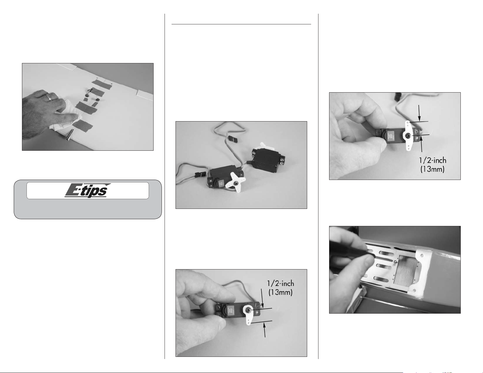
3. Use the radio system to center the rudder servo.
Enlarge the hole in the servo arm that is 1/2-inch
(13mm) from the center of the servo for the rudder
pushrod. Use side cutters to remove the shorter
arms from the horn so they don’t interfere with the
operation of the servo. Make sure to leave the two
arms as shown: one connects to the rudder, the
other connects to the nose gear steering. Do not
enlarge any of the holes on the side of the arm for
the steering pushrod.
We recommend working through the next two sections
of the manual to allow the epoxy to fully cure.
4. Use a #1 Phillips screwdriver to thread a
servo mounting screw in each of the eight servo
mounting holes. This will cut threads into the
surrounding wood.
2. Use the radio system to center the elevator
servo. Enlarge the hole in the servo arm that is
1/2-inch (13mm) from the center of the servo. Use
side cutters to remove the remaining arms from
the horn so they don’t interfere with the operation
of the servo.
11E-flite Advance 25e ARF Assembly Manual
Page 12

5. Apply 2–3 drops of thin CA in each of the servo
mounting holes. This will harden the threads in the
surrounding wood, which will help prevent the servo
mounting screws from vibrating loose.
6. Mount the rudder and elevator servos in the
fuselage. Make sure to guide the servo leads
through the radio tray. Use a #1 Phillips screwdriver
to tighten the servo mounting screws.
7. Use scissors to cut two small pieces of hook and
loop tape to fit the main and remote receivers.
Apply the tape to the receivers as shown.
8. Mount the main receiver in the fuselage using the
hook and loop tape. Plug the rudder, elevator and
Y-harness for the aileron servos into the receiver at
this time.
9. Secure the remote receiver to the fuselage side
using the hook and loop tape.
12 E-flite Advance 25e ARF Assembly Manual
Page 13

Nose Gear Installation
Required Parts
Fuselage assembly Nose gear mount
Nylon clevis Silicone tubing
Nose gear wire Wheel, 2-inch (51mm)
Nylon spacer 3mm x 15mm machine screw (4)
Steering arm with screw
Wheel collar with screw
Pushrod wire, 24-inch (610mm)
Nylon tube, 117/8-inch (302mm)
Required Tools and Adhesives
Ruler Medium grit sandpaper
Threadlock Phillips screwdriver: #1
Felt-tipped pen Hobby knife with #11 blade
Pliers Side cutter
Medium CA Flat file
1. Use medium grit sandpaper to lightly sand a
1/4-inch (6mm) wide section of the 117/8-inch
(302mm) pushrod tube. This provides a surface for
the CA to bond to when the pushrod is glued in the
fuselage. Use the photo to locate the areas that are
21/4-inch (57mm) and 6-inches (147mm) from the
end of the tube.
2. Remove the battery cover by rotating the knob on
the cover 90-degrees. Lift the cover and set it aside
in a safe location.
3. Slide the pushrod tube into the fuselage
through the oval hole in the firewall with the
21/4-inch (57mm) sanded end first. The tube
will be routed up through the battery tray, then
through the hole in the former near the servo
tray. With the end of the tube flush with the
firewall, use medium CA to glue the tube where
it crosses the formers inside the fuselage.
Always use threadlock on metal-to-metal fasteners.
4. Attach the nose gear mount to the firewall using
four 3mm x 15mm machine screws and a #1
Phillips screwdriver.
13E-flite Advance 25e ARF Assembly Manual
Page 14

Always use threadlock on metal-to-metal fasteners.
5. Position the steering arm in the nose gear mount.
Slide the nose gear wire through the mount and
steering arm so it is flush with the top of the nose
gear mount. The steering arm will angle away from
the firewall so the nose wheel can operate properly.
Use a #1 Phillips screwdriver to tighten the screw in
the steering arm so it rests on the flat area on the
nose gear wire.
9. Use pliers to make a 90-degree bend in the wire.
Use side cutters to trim the wire 3/8-inch (9mm)
past the bend as shown.
Use the rudder trim on the radio to trim the
model in flight. If the model does not track
straight on the runway, adjust the clevis on
the steering linkage. Do not use the rudder
trim to correct the steering on your model.
7. Slide the steering pushrod wire into the tube from
the inside of the fuselage. Connect the clevis to the
outer hole of the rudder servo horn.
10. Insert the wire through the outer hole in the
steering arm. You may have to disassemble the nose
gear assembly to fit the wire through the hole.
8. Center the nose gear wire. The axle (where the
6. Use a hobby knife with a #11 blade to cut a 1/4-
inch (6mm) piece from the silicone tube. Slide the small
piece of tubing on a nylon clevis. Thread the clevis
wheel mounts) will be parallel to the firewall. Use
a felt-tipped pen to mark the pushrod wire where it
crosses the outer hole of the steering arm.
12-turns on a 24-inch (610mm) threaded pushrod
wire. This will provide enough thread in the clevis to be
secure and allow for adjustment of the linkage.
14 E-flite Advance 25e ARF Assembly Manual
Page 15

11. Use a flat file to make a 1/4-inch (6mm) wide
flat area on the nose gear wire that is 1/2-inch
(13mm) from the end of the wire. This will give the
screw in the wheel collar a place to rest, making it
more secure when installed.
12. Slide the nylon spacer on the nose gear wire,
then the 2-inch (51mm) wheel.
Always use threadlock on metal-to-metal fasteners.
13. Secure the wheel to the nose gear wire using a
wheel collar and a #1 Phillips screwdriver to tighten
the screw.
Motor Installation
Required Parts
Transmitter Fuselage assembly
Power 25 motor with hardware
40-Amp speed control (ESC) for Power 25
Propeller, 12 x 8
3200mAh 3S 11.1V motor battery (charged)
Hook and loop strap (2)
Hook and loop tape
Servo extension, 3-inch (76mm)
Required Tools and Adhesives
Threadlock Phillips screwdriver: #2
Scissors Hex wrench: 2.5mm
Optional Required Parts
Power 32 motor with hardware
60-Amp speed control (ESC) for Power 32
Plywood adapter plate for Power 32
Propeller, 12 x 6
3200mAh 4S 14.8V motor battery (charged)
Optional Tools and Accessories
Spinner
Box wrench: 10mm
Hex wrench: 3/32-inch
Always use threadlock on metal-to-metal fasteners.
1. Use a #2 Phillips screwdriver to attach the
X-mount to the back of the motor using the
hardware provided with the motor.
15E-flite Advance 25e ARF Assembly Manual
Page 16

Always use threadlock on metal-to-metal fasteners.
POWER 25 SPECIFIC
2. Attach the motor to the firewall using the
hardware provided with the motor. Guide the leads
from the motor through the hole in the firewall. Use
a 2.5mm hex wrench to tighten the bolts securing
the motor to the firewall.
POWER 32 SPECIFIC
2A. Locate the plywood spacer. The spacer will be
placed between the motor and firewall. Check the fit
of the spacer, as it will be notched for the nose gear
mount and will line up with the holes in the firewall
for the motor. There is a front and back to the
spacer, so if the holes don’t line up, flip it around so
that they do.
2B. Guide the leads from the motor through the
hole in the firewall. Use the hardware provided with
the motor to attach it to the firewall. Use a 2.5mm
hex wrench to tighten the bolts securing the motor to
the firewall.
3. Insert the hook and loop straps through the
slots in the battery tray. Make sure not to get the
steering pushrod inside the straps as this will cause
the steering linkage to bind, possibly damaging the
rudder servo.
Matching the colors between the ESC and motor
when they are connected results in the correct
motor direction if using all E-flite components.
4. Connect the leads from the motor to the leads
from the speed control. Use hook and loop tape
to secure the speed control inside the fuselage as
shown.
16 E-flite Advance 25e ARF Assembly Manual
Page 17

When mounting the 60-amp speed control for the
Power 32, make sure to secure the switch on the
speed control where it can be easily accessed.
5. Connect the lead from the speed control to the
receiver using a 3-inch (76mm) servo extension.
6. Apply the remaining hook and loop tape to the
bottom of the battery. This will keep the battery from
moving forward or aft in the fuselage.
Always balance your propeller. An unbalanced
propeller can cause vibrations to be transmitted
into the airframe, which could damage the
airframe or other components as well as
produce unwanted flight characteristics.
9. Use the propeller adapter to secure the
propeller to the motor. Slide a 2.5mm-inch hex
wrench through the hole in the adapter to tighten
it, securing the propeller.
7. Use the hook and loop straps to secure the
battery to the battery tray.
8. Turn on the transmitter. Connect the battery to the
power lead of the speed control. Check the rotation
of the motor to make sure it rotates counterclockwise
when viewed from the front of the fuselage. If not,
swap any two of the motor leads to correct the
direction of rotation.
We recommend using the optional spinner
to enhance the looks of your model.
17E-flite Advance 25e ARF Assembly Manual
Page 18

Main Landing Gear Installation
Required Parts
Wing assembly Main gear wire (2)
Nylon spacer (2) Nylon landing gear strap (4)
3mm x 10mm sheet metal screw (8)
Wheel collar with screw (2)
Wheel, 21/4-inch (57mm) (2)
Required Tools and Adhesives
Flat file Phillips screwdriver: #1
Drill Drill bit: 1/16-inch (1.5mm)
Thin CA Threadlock
Low-tack tape Ruler
Felt-tipped pen
1. Insert the landing gear into the channel in the
bottom of the wing. The gear will fit flush with the
bottom of the wing.
3. Center the nylon landing gear strap over the
gear wire and the mark made in the previous step.
Use a felt-tipped pen to transfer the locations for the
mounting screws to the bottom of the wing.
Wrap a small piece of low-tack tape around a
1/16-inch drill bit so it is 1/2-inch (13mm) from
the end of the bit. This will help in preventing
drilling through the top of the wing when
drilling the holes for the mounting screws.
4. Use a drill and 1/16-inch (1.5mm) drill bit
to drill the four holes for the landing gear strap
mounting screws.
5. Use a #1 Phillips screwdriver to thread a 3mm x
10mm sheet metal screw in each of the holes. This
will cut threads into the surrounding wood.
2. Use a felt-tipped pen and ruler to make two
marks that are 1/2-inch (13mm) from the ends of
the wire as shown.
18 E-flite Advance 25e ARF Assembly Manual
Page 19

6. Apply 2–3 drops of thin CA in each of the holes.
This will harden the threads in the surrounding
wood, which will help prevent the screws from
vibrating loose.
7. Use a #1 Phillips screwdriver to attach the nylon
landing gear straps using four 3mm x 10mm sheet
metal screws.
8. Use a flat file to make a 1/4-inch (6mm) wide
flat area on the main gear wire that is 1/2-inch
(13mm) from the end of the wire. This will give the
screw in the wheel collar a place to rest, making it
more secure when installed.
9. Slide the nylon spacer on the main gear wire,
then the 21/4-inch (57mm) wheel.
10. Secure the wheel to the main gear wire using a
wheel collar and a #1 Phillips screwdriver to tighten
the screw.
11. Repeat Steps 1 through 10 to install the
remaining main gear wire and wheel.
Always use threadlock on metal-to-metal fasteners.
19E-flite Advance 25e ARF Assembly Manual
Page 20

Wing Installation
Required Parts
Wing assembly Fuselage assembly
4mm x 25mm machine screws
Plywood wing bolt plate
Required Tools and Adhesives
Felt-tipped pen Hobby knife with #11 blade
Medium CA Phillips screwdriver: #2
Paper towel Rubbing alcohol
Before installing the wing bolt plate, draw a centerline
on the underside of the plate and lightly score the
plate so it can easily conform to the dihedral angle
of the wing. Use care not to cut through the plate.
1. Place the plywood wing bolt plate on the bottom
of the wing. Trace the outline of the wing bolt plate
on the bottom of the wing. We used the two 4mm
x 25mm machine screws to keep the plate in the
correct position.
When cutting through the covering, use a
new #11 blade and light pressure to avoid
cutting into the underlying wood, which could
weaken the underlying structure, causing it
to fail in flight. We also recommend using a
hot knife to melt through the covering to help
reduce damaging the underlying wood.
2. Remove the plate from the wing. Use a hobby
knife and #11 blade to trim the covering inside
the lines drawn in the previous step by 1/16-inch
(1.5mm). Remove the covering, exposing the bare
wood. The lines can be removed using a paper
towel and rubbing alcohol.
4. Connect the leads between the aileron Y-harness
and aileron servos.
5. Place the wing on the fuselage. Make sure
the aileron servo leads are tucked in and not
exposed between the wing and fuselage. Use two
4mm x 25mm machine screws and a #2 Phillips
screwdriver to secure the wing to the fuselage.
3. Use medium CA to glue the wing bolt plate to the
bottom of the wing. Make sure the holes are aligned
before the CA fully cures.
20 E-flite Advance 25e ARF Assembly Manual
Page 21

Stabilizer and Vertical Fin Installation
B
A A
B
B=B
A=A
Equal Distance
Required Parts
Airframe Stabilizer with elevator
Fin with rudder
Required Tools and Adhesives
Ruler Phillips screwdriver: #2
30-minute epoxy Hobby knife with #11 blade
Felt-tipped pen Square
Low-tack tape Paper towel
Mixing stick Mixing cup
Epoxy brush Rubbing alcohol
T-pins Medium grit sandpaper
1. Use a ruler and felt-tipped pen to draw a
reference line down the center of the stabilizer
saddle.
3. Use a hobby knife and a #11 blade to remove
the covering from the center slot of the stabilizer.
4. Place the stabilizer on the fuselage. Use the
line drawn on the stabilizer saddle in Step 1 to
help align the slot in the stabilizer on the stabilizer
saddle. With the stabilizer as far forward on the
saddle as possible, use two T-pins to keep the
stabilizer in position to check its alignment.
5. Measure the distance from each stabilizer tip to
the fuselage centerline to make sure the stabilizer
is centered on the fuselage (A=A). Measure the
distance from each stabilizer tip to its respective
wing tip (B=B). These measurements must match
as close as possible. Adjust the position of the
stabilizer if necessary to position the stabilizer.
2. Separate the elevator and stabilizer. Leave the six
hinges in the elevator so they don’t get lost. Set the
elevator aside in a safe location to be installed later.
6. Stand back 8–10 feet (2–3 meters) and view the
aircraft from the rear. Check the alignment between
the wing and stabilizer. They must be equal distance
on each side as shown. If not, lightly sand the
stabilizer saddle to correct any alignment problems.
It is important to check the alignment of the
stabilizer in relationship to the wing. Not doing
so may cause your airplane to require excessive
amounts of trim to correct for poor alignment,
resulting in poor flight performance.
21E-flite Advance 25e ARF Assembly Manual
Page 22

7. Once the stabilizer has been aligned to the wing,
use a felt-tipped pen to trace the outline of the
fuselage on the bottom of the stabilizer.
The following steps must be completed
before the epoxy begins to cure. Make
sure to read through and understand the
following steps before mixing any epoxy.
9. Mix 1/2 ounce (15mL) of 30-minute epoxy.
Apply a thin coat of epoxy on the stabilizer saddle
with an epoxy brush.
11. Place the stabilizer back on the fuselage.
Recheck the alignment, then use T-pins to hold
the stabilizer in position. Use a paper towel and
rubbing alcohol to remove any excess epoxy before
it cures. Set the fuselage aside until the epoxy fully
cures.
Use care not to get epoxy in the slot at the
center of the stabilizer. This will change the fit
of the fin in the slot when it is installed.
12. Once the epoxy has fully cured, use a #2
Phillips screwdriver to remove the wing from the
fuselage. Set the wing aside in a safe location until
instructed to install it again.
When cutting through the covering, use a
new #11 blade and light pressure to avoid
cutting into the underlying wood, which could
weaken the underlying structure, causing it
to fail in flight. We also recommend using a
hot knife to melt through the covering to help
reduce damaging the underlying wood.
8. Remove the stabilizer from the fuselage. Use a
hobby knife and #11 blade to trim the covering
inside the lines drawn in the previous step by 1/16inch (1.5mm). Remove the covering, exposing the
bare wood. The lines can be removed using a
paper towel and rubbing alcohol.
13. Separate the rudder from the fin. Leave the
three hinges in the rudder so they don’t get lost.
Set the rudder aside in a safe location to be
installed later.
10. Use an epoxy brush to apply a thin coat of
epoxy to the exposed wood on the stabilizer.
22 E-flite Advance 25e ARF Assembly Manual
Page 23

14. Remove the T-pins from the stabilizer. Position
the fin in the slot in the stabilizer. It must rest tightly
against the stabilizer. Use a felt-tipped pen to
transfer the top edge of the stabilizer on the bottom
of the fin.
15. Use a felt-tipped pen to trace the outline of the
fin on the top of the stabilizer.
16. Use a hobby knife and #11 blade to remove
the covering from the fin 1/16-inch (1.5mm) below
the line drawn in the previous steps.
17. Use a hobby knife and #11 blade to trim the
covering inside the lines drawn on the stabilizer by
1/16-inch (1.5mm). Remove the covering, exposing
the bare wood. The lines can be removed using a
paper towel and rubbing alcohol.
19. Apply a thin coat of epoxy to the exposed
wood at the bottom of the fin.
20. Place the fin in position in the slot. Use
a square to make sure the fin is perpendicular
to the stabilizer.
When cutting through the covering, use a
new #11 blade and light pressure to avoid
cutting into the underlying wood, which could
weaken the underlying structure, causing it
to fail in flight. We also recommend using a
hot knife to melt through the covering to help
reduce damaging the underlying wood.
The following steps must be completed
before the epoxy begins to cure. Make
sure to read through and understand the
following steps before mixing any epoxy.
18. Mix 1/2 ounce (15mL) of 30-minute epoxy.
Apply a thin coat of epoxy to the exposed wood
and in the slot on the top of the stabilizer.
21. Use low-tack tape and T-pins to keep the fin
in position until the epoxy fully cures. Use a paper
towel and rubbing alcohol to remove any excess
epoxy before it cures.
23E-flite Advance 25e ARF Assembly Manual
Page 24

Hinging the Elevator and Rudder
Required Parts
Fuselage assembly Rudder with hinges
Elevator with hinges
Required Tools and Adhesives
Pin vise Drill bit: 1/16-inch
Thin CA T-pins
1. Use a pin vise and 1/16-inch (1.5mm) drill bit
to drill a hole in the center of each hinge slot in the
stabilizer. This will provide a tunnel for the CA to
wick into, making the bond between the hinge and
wood stronger.
3. Slide the hinges into the elevator. Insert the
hinges so the holes in the hinge are at the hinge
line. Insert a T-pin through one of the holes to keep
the hinge centered when the elevator is installed on
the stabilizer.
4. Slide the six hinges in the elevator into the slots
on the stabilizer. Check that the ends of the elevator
are aligned with the ends of the stabilizer.
When gluing the hinges, do not use a CA
accelerator. The CA must be allowed time to
soak into the hinges to provide the best bond
between the hinge and surrounding wood.
5. Remove the T-pins from the hinges. Make sure
the elevator is tight against the stabilizer. Wick thin
CA into each hinge, both top and bottom, until the
hinge is saturated with CA. Allow the CA to fully
cure before proceeding.
6. Once the CA has fully cured, gently pull on the
elevator and stabilizer to make sure the hinges are
2. Remove the hinges from the elevator. Prepare
the elevator for hinging following the procedure
described in Step 1.
24 E-flite Advance 25e ARF Assembly Manual
glued securely. If not, reapply thin CA to any hinges
that are not secure.
Page 25

7. Flex the elevator through its range of motion
a number of times to break in the hinges. This
will reduce the initial load on the servo for
your first flights.
Rudder and Elevator
Linkage Installation
Required Parts
Fuselage assembly Transmitter
Silicone tubing Nylon clevis (2)
Nylon control horn with backplate (2)
2mm x 12mm machine screw (4)
Pushrod wire, 24-inch (610mm) (2)
Required Tools and Adhesives
Pin vise Drill bit: 5/64-inch (2mm)
Pliers Felt-tipped pen
Thin CA Hobby knife with #11 blade
Ruler Phillips screwdriver: #1
Side cutter
1. Use a hobby knife with a #11 blade to cut
a 1/4-inch (6mm) piece from the silicone tube.
Slide the small piece of tubing on a nylon clevis.
Thread the clevis 12-turns on a 24-inch (610mm)
threaded pushrod wire. This will provide enough
thread in the clevis to be secure and allow for
adjustment of the linkage.
2. Attach the clevis to the outer hole on the nylon
control horn.
3. Slide the pushrod in the preinstalled elevator
pushrod tube.
8. Repeat Steps 1 through 7 to attach the rudder to
the fin and fuselage using three CA hinges.
25E-flite Advance 25e ARF Assembly Manual
Page 26

4. Rest the control horn on the elevator so the holes
in the horn align with the elevator hinge line. The
pushrod wire will help aligning the horn. Use a
felt-tipped pen to mark the locations for the control
horn screws.
5. Use a pin vise and 5/64-inch (2mm) drill bit
to drill the two holes for the elevator control horn
mounting screws.
6. Apply 2–3 drops on thin CA in each of the holes
to harden the surrounding wood. This will keep the
control horn secure and prevent the surrounding
wood from becoming damaged over time.
7. Attach the control horn to the elevator using two
2mm x 12mm machine screws and the control horn
backplate. Use a #1 Phillips screwdriver to tighten
the screws. Make sure not to over-tighten the screws
and damage the underlying wood.
8. Use a ruler to check that the elevator and
stabilizer are in alignment with one another.
9. Use the radio system to center the elevator servo.
Use a felt-tipped pen to mark the pushrod where it
crosses the hole in the elevator servo horn that was
enlarged previously.
Making a Z-bend takes some skill. There is
plenty of excess wire to experiment with. We
recommend using Z-bend pliers (HAN119) to
make the perfect Z-bend in your pushrod wire.
26 E-flite Advance 25e ARF Assembly Manual
Page 27

10. Make a Z-bend in the pushrod wire using a
pair of pliers. It may be necessary to disconnect the
clevis from the control horn to make the bend in the
pushrod wire.
11. Remove the servo horn from the servo. Insert
the bend in the hole of the servo horn. Secure the
control horn back on the servo using a #1 Phillips
screwdriver. Reconnect the clevis to the outer hole
of the control horn. Slide the silicone tube over
the forks of the clevis to prevent it from opening
accidentally in flight. Use side cutters to remove
any excess pushrod that might interfere with the
operation of the radio system.
12. Repeat Steps 1 through 11 to install the
rudder linkage.
Optional Pilot Installation
Required Parts
Fuselage assembly Pilot
Required Tools and Adhesives
Felt-tipped pen Scissors
Silicone adhesive Hobby knife with #11 blade
Note: Skip to the next section of the manual if
you are not installing the optional pilot.
1. Use a felt-tipped pen to trace a line on the pilot
figure that is up 1/4-inch (6mm) from the bottom
of the pilot.
2. Use a hobby knife and scissors to trim the pilot
along the line drawn in the previous step.
27E-flite Advance 25e ARF Assembly Manual
Page 28

3. Use silicone adhesive to glue the pilot figure in the
cockpit. The pilot will be centered 2-inches (52mm)
forward of the back of the cockpit as shown.
Canopy Installation - Option 1
Required Parts
Fuselage assembly Canopy
2mm x 8mm sheet metal screw (4)
Required Tools and Adhesives
Drill Drill bit: 1/16-inch (1.5mm)
Low-tack tape Thin CA
Phillips screwdriver: #1
We show two different options for the canopy
installation. The second option can be found on
Page 29.
1. Use low-tack tape to tape the canopy to the
fuselage. Make sure it is centered left-to-right
on the fuselage.
3. Remove the canopy from the fuselage. Apply
2–3 drops of thin CA in each hole to harden the
surrounding wood. Allow the CA to fully cure to
prevent getting any on the canopy.
2. Use a pin vise and 1/16-inch (1.5mm) drill bit to
drill four mounting holes for the canopy. Position the
holes as far forward and rearward as possible.
28 E-flite Advance 25e ARF Assembly Manual
4. Attach the canopy using four 2mm x 8mm sheet
metal screws and a #1 Phillips screwdriver.
Page 29

Canopy Installation - Option 2
Required Parts
Fuselage assembly Canopy
Striping tape
Required Tools and Adhesives
Low-tack tape Canopy glue
3. Remove the low-tack tape once the glue has fully
cured. Apply the striping tape around the edge of
the canopy. Work slowly, pulling the tape to stretch
it around the curves at the front of the canopy.
Decal Installation
Required Parts
Fuselage assembly Wing assembly
Required Tools and Adhesives
Spray bottle Dish washing detergent
Paper towel Hobby knife with #11 blade
1. Apply a thin bead of canopy glue around the
perimeter of the canopy.
2. Use low-tack tape to hold the canopy in position
on the fuselage. Make sure it is centered left-to-right
on the fuselage.
1. Apply the decals to your model using the photos
located in this section of the manual and the box
art from your model. Use a spray bottle and a drop
of dish washing liquid sprayed in the location of
the decal to allow repositioning of the decal. Use
a paper towel as a squeegee to remove excess
water from under the decal. Allow the model to rest
overnight so the remaining water can evaporate.
29E-flite Advance 25e ARF Assembly Manual
Page 30

Center of Gravity
Balancing Stand
Required Parts
Assembled airframe
Required Tools and Adhesives
Felt-tipped pen Ruler
Phillips screwdriver: #2
Balancing stand (optional)
3. When balancing your model, support the plane
inverted at the marks made on the top of the wing
with your fingers or a commercially available
balancing stand. This is the correct balance point
for your model. Make sure your model is assembled
and ready for flight before balancing.
Control Throws
1. Turn on the transmitter and receiver of your
model. Check the movement of the rudder using
the transmitter. When the stick is moved right, the
rudder should also move right. Reverse the direction
of the servo at the transmitter if necessary.
An important part of preparing the aircraft for flight is
properly balancing the model.
CAUTION: Do not inadvertently skip this step or
property damage and injury could occur.
1. Assemble your model in preparation for flight,
making sure the wing is on securely and the motor
battery is installed as instructed in this manual.
2. The recommended Center of Gravity (CG)
location for your model is 3 to 31/2 inches (76 to
89mm) back from the leading edge of the wing
as shown with the battery pack installed. Mark the
location of the CG on the top of the wing with a
felt-tipped pen.
Adjust the motor battery as necessary so the model is
level or slightly nose down. This is the correct balance
point for your model. You should find the CG to be
very close with the battery installed as shown in this
manual. Mark the location of the battery on the battery
tray using a felt-tipped pen so it can be returned to this
position if it is removed from your model.
After the first flights, the CG position can be adjusted
for your personal preference.
2. Check the movement of the elevator with the
radio system. Moving the elevator stick toward
the bottom of the transmitter makes the airplane
elevator move up.
3. Check the movement of the ailerons with the
radio system. Moving the aileron stick right makes
the right aileron move up and the left aileron
move down.
4. Use a ruler to adjust the throw of the elevator,
ailerons and rudder. Adjust the position of
the pushrod at the control horn to achieve the
following measurements when moving the sticks to
their endpoints.
Elevator High Rate (100%) (20% Exponential)
Up 19/32-inch (15mm) 23 degrees
Down 23/32-inch (18mm) 25 degrees
Elevator Low Rate (15% Exponential)
Up 11/32-inch (8.5mm) 13 degrees
Down 13/32-inch (10.5mm) 15 degrees
Aileron High Rate (100%) (20% Exponential)
Up 17/32-inch (13.5mm) 25 degrees
Down 17/32-inch (13.5mm) 25 degrees
Aileron Low Rate (15% Exponential)
Up 13/32-inch (10.5mm) 19 degrees
Down 13/32-inch (10.5mm) 19 degrees
30 E-flite Advance 25e ARF Assembly Manual
Page 31

Rudder High Rate (100%) (20% Exponential)
Right 27/8-inch (73mm) 35 degrees
Left 27/8-inch (73mm) 35 degrees
Rudder Low Rate (15% Exponential)
Right 21/4-inch (57mm) 25 degrees
Left 21/4-inch (57mm) 25 degrees
Measurements are taken at the inner or
widest point on the control surface.
These are general guidelines measured from our own
flight tests. You can experiment with higher rates to
match your preferred style of flying.
Travel Adjust and Sub-Trims are not listed
and should be adjusted according to each
individual model and preference.
We highly recommend re-binding the radio
system once all the control throws are set. This will
keep the servos from moving to their endpoints
until the transmitter and receiver connect.
Preflight
Check Your Radio
Before going to the field, be sure your batteries are
fully charged per the instructions included with your
radio. Charge the transmitter and motor battery
for your airplane. Use the recommended charger
supplied with your particular radio system, following
the instructions provided with the radio. In most
cases, the radio should be charged the night before
going out flying.
Before each flying session, be sure to range check your
radio. See your radio manual for the recommended
range and instructions for your radio system. Each
radio manufacturer specifies different procedures for
their radio systems. Next, run the motor. With the
model securely anchored, check the range again.
The range test should not be significantly affected. If
it is, don’t attempt to fly! Have your radio equipment
checked out by the manufacturer.
Double-check that all controls (aileron, elevator, rudder
and throttle) move in the correct direction.
Check the radio installation and make sure all the
control surfaces are moving correctly (i.e., the correct
direction and with the recommended throws).
Check all the control horns, servo horns, and clevises
to make sure they are secure and in good condition.
Flying Your Advance 25e ARF
The Advance 25e is a very spirited flyer yet is gentle
and forgiving during takeoff and landing.
Ground handling is easy due to the tricycle landing
gear. When on the runway, set the throttle trim to so
the motor is spinning low RPM. Then smoothly apply
power and apply a small amount of up elevator during
your takeoff roll. Make small corrections with the
rudder to keep the airplane tracking straight down the
runway. The Advance will lift off of the ground gently
and smoothly and settle into a gentle climb angle.
Once at altitude, trim the airplane at a cruise power
setting of ½ to ¾ throttle. After trimming and making a
few passes, try some slow speed flight at altitude. The
airplane is very stable at low airspeeds and during a
stall; it will break very gently straight ahead.
The Advance is easily capable of aerobatics such
as loops, rolls, spins, inverted flight and even knife
edge. Combine these to create an endless amount of
aerobatic maneuvers.
When setting up to land, reduce power and begin to
bleed off airspeed. Fly a traffic pattern and continue to
lose altitude. Line up to the runway on final approach
and allow the Advance to continue to descend. When
a few feet above the runway, begin to flare with up
elevator. Once the airplane settles into ground effect, it
will set down gently at a slightly nose-high attitude. If
the nose is kept high on roll out, the airplane will bleed
off speed much quicker. Use small corrections to keep
the airplane tracking straight down the runway.
Congratulations, you have just successfully flown
your Advance 25e! We hope you have many more
enjoyable flights with this model.
Happy Landings!
31E-flite Advance 25e ARF Assembly Manual
Page 32

Range Test Your Radio
Daily Flight Checks
Warranty and Repair Policy
Before each flying session, and especially with a new
model, it is important to perform a range check. It
is helpful to have another person available to assist
during the range check. If you are using a Spektrum
transmitter, please refer to your transmitter’s manual for
detailed instructions on the range check process.
1. With the model resting on the ground, stand 30
paces (approximately 90 feet) away from the model.
2. Face the model with the transmitter in your
normal flying position. Be sure the throttle is in the
full down position and plug the flight battery into
the speed control.
3. As you move the controls, watch to be sure the
airplane’s motor and controls operate smoothly.
You should have total control of the model at 30
paces (90 feet).
4. If control issues exist, call the appropriate
Horizon Product Support office (see page 43) or
go to horizonhobby.com to find a local Spektrum
distributor in your country for service if using a
Spektrum radio system.
1. Check the battery voltage of the transmitter
battery. Do not fly below the manufacturer’s
recommended voltage. To do so can crash
your aircraft.
When you check these batteries, ensure you have the
polarities correct on your expanded scale voltmeter.
2. Check all hardware (linkages, screws, nuts, and
bolts) prior to each day’s flight. Be sure that binding
does not occur and that all parts are properly
secured.
3. Ensure all surfaces are moving in the
proper manner.
4. Perform a ground range check before each
flying session.
5. Prior to starting your aircraft, turn off your
transmitter, then turn it back on. Do this each time
you start your aircraft. If any critical switches are on
without your knowledge, the transmitter alarm will
sound a warning at this time.
WARRANTY PERIOD
Exclusive Warranty- Horizon Hobby, Inc., (Horizon)
warranties that the Products purchased (the “Product”)
will be free from defects in materials and workmanship
at the date of purchase by the Purchaser.
LIMITED WARRANTY
Horizon reserves the right to change or modify this
warranty without notice and disclaims all other
warranties, express or implied.
(a) This warranty is limited to the original Purchaser
(“Purchaser”) and is not transferable. REPAIR
OR REPLACEMENT AS PROVIDED UNDER THIS
WARRANTY IS THE EXCLUSIVE REMEDY OF THE
PURCHASER. This warranty covers only those Products
purchased from an authorized Horizon dealer. Third
party transactions are not covered by this warranty.
Proof of purchase is required for all warranty claims.
(b) Limitations- HORIZON MAKES NO WARRANTY
OR REPRESENTATION, EXPRESS OR IMPLIED,
ABOUT NON-INFRINGEMENT, MERCHANTABILITY
OR FITNESS FOR A PARTICULAR PURPOSE OF THE
PRODUCT. THE PURCHASER ACKNOWLEDGES
THAT THEY ALONE HAVE DETERMINED THAT THE
PRODUCT WILL SUITABLY MEET THE REQUIREMENTS
OF THE PURCHASER’S INTENDED USE.
6. Check that all trim levers are in the
proper location.
7. All servo pigtails and switch harness plugs should
be secured in the receiver. Make sure the switch
harness moves freely in both directions.
32 E-flite Advance 25e ARF Assembly Manual
(c) Purchaser Remedy- Horizon’s sole obligation
hereunder shall be that Horizon will, at its option,
(i) repair or (ii) replace, any Product determined
by Horizon to be defective. In the event of a defect,
these are the Purchaser’s exclusive remedies. Horizon
reserves the right to inspect any and all equipment
involved in a warranty claim. Repair or replacement
decisions are at the sole discretion of Horizon.
This warranty does not cover cosmetic damage or
damage due to acts of God, accident, misuse, abuse,
negligence, commercial use, or modification of or
to any part of the Product. This warranty does not
cover damage due to improper installation, operation,
maintenance, or attempted repair by anyone other
than Horizon. Return of any Product by Purchaser must
be approved in writing by Horizon before shipment.
Page 33

DAMAGE LIMITS
Warranty Services
WARRANTY INSPECTION AND REPAIRS
HORIZON SHALL NOT BE LIABLE FOR SPECIAL,
INDIRECT OR CONSEQUENTIAL DAMAGES, LOSS
OF PROFITS OR PRODUCTION OR COMMERCIAL
LOSS IN ANY WAY CONNECTED WITH THE
PRODUCT, WHETHER SUCH CLAIM IS BASED IN
CONTRACT, WARRANTY, NEGLIGENCE, OR STRICT
LIABILITY. Further, in no event shall the liability of
Horizon exceed the individual price of the Product on
which liability is asserted. As Horizon has no control
over use, setup, final assembly, modification or misuse,
no liability shall be assumed nor accepted for any
resulting damage or injury. By the act of use, setup or
assembly, the user accepts all resulting liability.
If you as the Purchaser or user are not prepared
to accept the liability associated with the use of
this Product, you are advised to return this Product
immediately in new and unused condition to the place
of purchase.
Law: These Terms are governed by Illinois law (without
regard to conflict of law principals).
QUESTIONS, ASSISTANCE, AND REPAIRS
Your local hobby store and/or place of purchase
cannot provide warranty support or repair. Once
assembly, setup or use of the Product has been started,
you must contact Horizon directly. This will enable
Horizon to better answer your questions and service
you in the event that you may need any assistance.
For questions or assistance, please direct your
email to productsupport@horizonhobby.com, or call
877.504.0233 toll free to speak to a Product Support
representative. You may also find information on our
website at www.horizonhobby.com.
INSPECTION OR REPAIRS
If this Product needs to be inspected or repaired,
please use the Horizon Online Repair Request
submission process found on our website or call
Horizon to obtain a Return Merchandise Authorization
(RMA) number. Pack the Product securely using a
shipping carton. Please note that original boxes may
be included, but are not designed to withstand the
rigors of shipping without additional protection. Ship
via a carrier that provides tracking and insurance for
lost or damaged parcels, as Horizon is not responsible
for merchandise until it arrives and is accepted at
our facility. An Online Repair Request is available at
www.horizonhobby.com http://www.horizonhobby.
com under the Repairs tab. If you do not have internet
access, please contact Horizon Product Support to
obtain a RMA number along with instructions for
submitting your product for repair. When calling
Horizon, you will be asked to provide your complete
name, street address, email address and phone
number where you can be reached during business
hours. When sending product into Horizon, please
include your RMA number, a list of the included items,
and a brief summary of the problem. A copy of your
original sales receipt must be included for warranty
consideration. Be sure your name, address, and
RMA number are clearly written on the outside of the
shipping carton.
Notice: Do not ship batteries to Horizon. If
you have any issue with a battery, please
contact the appropriate Horizon Product
Support office.
To receive warranty service, you must include your
original sales receipt verifying the proof-of-purchase
date. Provided warranty conditions have been met,
your Product will be repaired or replaced free of
charge. Repair or replacement decisions are at the sole
discretion of Horizon.
NON-WARRANTY REPAIRS
Should your repair not be covered by warranty
the repair will be completed and payment will
be required without notification or estimate of
the expense unless the expense exceeds 50% of
the retail purchase cost. By submitting the item for
repair you are agreeing to payment of the repair
without notification. Repair estimates are available
upon request. You must include this request with your
repair. Non-warranty repair estimates will be billed a
minimum of ½ hour of labor. In addition you will be
billed for return freight. Horizon accepts money orders
and cashiers checks, as well as Visa, MasterCard,
American Express, and Discover cards. By submitting
any item to Horizon for inspection or repair, you are
agreeing to Horizon’s Terms and Conditions found on
our website under the Repairs tab.
UNITED STATES
(Electronics and engines)
Horizon Service Center
4105 Fieldstone Rd
Champaign, Illinois
61822 USA
877-504-0233
Online Repair Request visit:
www.horizonhobby.com/repairs
(All other products)
Horizon Product Support
4105 Fieldstone Rd
Champaign, Illinois
61822 USA
productsupport@horizonhobby.com
877-504-0233
33E-flite Advance 25e ARF Assembly Manual
Page 34

UNITED KINGDOM
Horizon Hobby Limited
Units 1-4 Ployters Rd
Staple Tye
Harlow, Essex
CM18 7NS
United Kingdom
sales@horizonhobby.co.uk
+44 (0) 1279 641 097
GERMANY
Horizon Technischer Service
Hamburger Str. 10
25335 Elmshorn
Germany
service@horizonhobby.de
+49 4121 46199 66
FRANCE
Horizon Hobby SAS
14 Rue Gustave Eiffel
Zone d’Activité du Réveil Matin
91230 Montgeron
infofrance@horizonhobby.com
+33 (0) 1 60 47 44 70
Compliance Information for the
European Union
INSTRUCTIONS FOR DISPOSAL OF WEEE BY
USERS IN THE EUROPEAN UNION
This product must not be disposed of with other waste.
Instead, it is the user’s responsibility to dispose of their
waste equipment by handing it over to a designated
collection point for the recycling of waste electrical
and electronic equipment. The separate collection
and recycling of your waste equipment at the time
of disposal will help to conserve natural resources
and ensure that it is recycled in a manner that
protects human health and the environment. For more
information about where you can drop off your waste
equipment for recycling, please contact your local city
office, your household waste disposal service or where
you purchased the product.
2010 Official Academy of Model
Aeronautics Safety Code
GENERAL
1. A model aircraft shall be defined as a non-humancarrying device capable of sustained flight in
the atmosphere. It shall not exceed limitations
established in this code and is intended to be used
exclusively for recreational or competition activity.
2. The maximum takeoff weight of a model aircraft,
including fuel, is 55 pounds, except for those flown
under the AMA Experimental Aircraft Rules.
3. I will abide by this Safety Code and all rules
established for the flying site I use. I will not
willfully fly my model aircraft in a reckless and/or
dangerous manner.
4. I will not fly my model aircraft in sanctioned events,
air shows, or model demonstrations until it has been
proven airworthy.
5. I will not fly my model aircraft higher than
approximately 400 feet above ground level, when
within three (3) miles of an airport without notifying
the airport operator. I will yield the right-of-way and
avoid flying in the proximity of full-scale aircraft,
utilizing a spotter when appropriate.
6. I will not fly my model aircraft unless it is
identified with my name and address, or AMA
number, inside or affixed to the outside of the
model aircraft. This does not apply to model
aircraft flown indoors.
7. I will not operate model aircraft with metal-blade
propellers or with gaseous boosts (other than
air), nor will I operate model aircraft with fuels
containing tetranitromethane or hydrazine.
8. I will not operate model aircraft carrying
pyrotechnic devices which explode burn, or
propel a projectile of any kind. Exceptions
include Free Flight fuses or devices that burn
producing smoke and are securely attached to
the model aircraft during flight. Rocket motors
up to a G-series size may be used, provided
they remain firmly attached to the model aircraft
during flight. Model rockets may be flown in
accordance with the National Model Rocketry
Safety Code; however, they may not be launched
from model aircraft. Officially designated AMA
Air Show Teams (AST) are authorized to use
devices and practices as defined within the Air
Show Advisory Committee Document.
9. I will not operate my model aircraft while under
the influence of alcohol or within eight (8) hours of
having consumed alcohol.
10. I will not operate my model aircraft while using
any drug which could adversely affect my ability to
safely control my model aircraft.
11. Children under six (6) years old are only allowed
on a flightline or in a flight area as a pilot or while
under flight instruction.
12. When and where required by rule, helmets must be
properly worn and fastened. They must be OSHA,
DOT, ANSI, SNELL or NOCSAE approved or
comply with comparable standards.
RADIO CONTROL
1. All model flying shall be conducted in a manner to
avoid over flight of unprotected people.
2. I will have completed a successful radio equipment
ground-range check before the first flight of a new
or repaired model aircraft.
34 E-flite Advance 25e ARF Assembly Manual
Page 35

3. I will not fly my model aircraft in the presence of
spectators until I become a proficient flier, unless I
am assisted by an experienced pilot.
8. Under no circumstances may a pilot or other person
touch a model aircraft in flight while it is still under
power, except to divert it from striking an individual.
4. At all flying sites a line must be established, in front
of which all flying takes place. Only personnel
associated with flying the model aircraft are allowed
at or in front of the line. In the case of airshows
demonstrations straight line must be established.
An area away from the line must be maintained
for spectators. Intentional flying behind the line is
prohibited.
5. I will operate my model aircraft using only
radio-control frequencies currently allowed by
the Federal Communications Commission (FCC).
Only individuals properly licensed by the FCC
are authorized to operate equipment on Amateur
Band frequencies.
6. I will not knowingly operate my model aircraft
within three (3) miles of any preexisting flying
site without a frequency-management agreement.
A frequency management agreement may be
an allocation of frequencies for each site, a
day-use agreement between sites, or testing
which determines that no interference exists. A
frequency-management agreement may exist
between two or more AMA chartered clubs, AMA
clubs and individual AMA members, or individual
AMA members. Frequency-management
agreements, including an interference test report if
the agreement indicates no interference exists, will
be signed by all parties and copies provided to
AMA Headquarters.
9. Radio-controlled night flying is limited to lowperformance model aircraft (less than 100 mph).
The model aircraft must be equipped with a lighting
system which clearly defines the aircraft’s attitude
and direction at all times.
10. The operator of a radio-controlled model aircraft
shall control it during the entire flight, maintaining
visual contact without enhancement other than by
corrective lenses that are prescribed for the pilot.
No model aircraft shall be equipped with devices
which allow it to be flown to a selected location
which is beyond the visual range of the pilot.
Advance 25e
Safe Operating Recommendations
- Inspect your model before every flight to make
certain it is airworthy.
- Be aware of any other radio frequency user who
may present an interference problem.
- Always be courteous and respectful of other
users of your selected flight area.
- Choose an area clear of obstacles and large
enough to safely accommodate your flying
activity.
- Make certain this area is clear of friends and
spectators prior to launching your aircraft.
- Be aware of other activities in the vicinity of your
flight path that could cause potential conflict.
- Carefully plan your flight path prior to launch.
7. With the exception of events flown under official
AMA rules, no powered model may be flown
outdoors closer than 25 feet to any individual,
except for the pilot and located at the flightline.
- Abide by any and all established AMA National
Model Aircraft Safety Code.
35E-flite Advance 25e ARF Assembly Manual
Page 36

© 2010 Horizon Hobby, Inc.
horizonhobby.com
www.e-fliterc.com
The Spektrum trademark is used with permission of Bachmann Industries, Inc.
E-flite, JR SPORT, DSM, DSM2 and UltraCote are trademarks or registered trademarks of
All other trademarks, ser vice marks and logos are the property of their respective owners.
28421 Created 09/2010
Horizon Hobby, Inc.
 Loading...