

Page 1
Adagio™ 280
Instruction Manual
Bedienungsanleitung
Manuel d’utilisation
Manuale di Istruzioni
Page 2
EN
NOTICE
All instructions, warranties and other collateral documents are subject to change at the sole discretion
of Horizon Hobby, LLC. For up-to-date product literature, visit www.horizonhobby.com and click on the
support tab for this product.
Meaning of Special Language:
The following terms are used throughout the product literature to indicate various levels of potential
harm when operating this product:
NOTICE: Procedures, which if not properly followed, create a possibility of physical property damage
AND little or no possibility of injury.
CAUTION: Procedures, which if not properly followed, create the probability of physical property
damage AND a possibility of serious injury.
WARNING: Procedures, which if not properly followed, create the probability of property damage,
collateral damage, and serious injury OR create a high probability of superfi cial injury.
WARNING: Read the ENTIRE instruction manual to become familiar with the features of the
product before operating. Failure to operate the product correctly can result in damage to the product,
personal property and cause serious injury.
This is a sophisticated hobby product. It must be operated with caution and common sense and requires
some basic mechanical ability. Failure to operate this product in a safe and responsible manner could
result in injury or damage to the product or other property. This product is not intended for use by
children without direct adult supervision. Do not use with incompatible components or alter this product
in any way outside of the instructions provided by Horizon Hobby, LLC. This manual contains instructions
for safety, operation and maintenance. It is essential to read and follow all the instructions and warnings
in the manual, prior to assembly, setup or use, in order to operate correctly and avoid damage or
serious injury.
WARNING AGAINST COUNTERFEIT PRODUCTS: If you ever need to replace your Spektrum receiver found
in a Horizon Hobby product, always purchase from Horizon Hobby, LLC or a Horizon Hobby authorized dealer
to ensure authentic high-quality Spektrum product. Horizon Hobby, LLC disclaims all support and warranty
with regards, but not limited to, compatibility and performance of counterfeit products or products claiming
compatibility with DSM or Spektrum.
Age Recommendation: Not for children under
14 years. This is not a toy.
Safety Precautions and Warnings
• Always keep a safe distance in all directions
around your model to avoid collisions or injury.
This model is controlled by a radio signal subject
to interference from many sources outside your
control. Interference can cause momentary loss
of control.
• Always operate your model in open spaces away
from full-size vehicles, traffi c and people.
• Always carefully follow the directions and
warnings for this and any optional support equipment (chargers, rechargeable battery packs, etc.).
• Always keep all chemicals, small parts and
anything electrical out of the reach of children.
• Always avoid water exposure to all equipment
not specifi cally designed and protected for this
purpose. Moisture causes damage to electronics.
• Never place any portion of the model in your
mouth as it could cause serious injury or
even death.
• Never operate your model with low transmitter
batteries.
• Always keep aircraft in sight and under control.
• Always use fully charged batteries.
• Always keep the transmitter powered on while
aircraft is powered.
• Always remove batteries before disassembly.
• Always keep moving parts clean.
• Always keep parts dry.
• Always let parts cool after use before touching.
• Always remove batteries after use.
• Always ensure failsafe is properly set
before fl ying.
• Never operate aircraft with damaged wiring.
• Never touch moving parts.
2
Page 3
Box Contents
Table of Contents
Prefl ight Checklist .................................................4
Wing Installation ...................................................4
Horizontal Tail Installation .....................................5
Low Voltage Cutoff (LVC) .......................................5
Transmitter and Receiver Binding .........................6
Battery Installation ................................................7
ESC Arming ..........................................................7
Control Direction Test ...........................................8
Control Centering .................................................8
Control Horn and Servo Arm Settings ....................8
Dual Rates ............................................................9
Center of Gravity (CG) ...........................................9
EN
Flying Tips and Repairs .......................................10
Post Flight Checklist ...........................................11
Service of Power Components ............................11
Troubleshooting Guide ........................................12
Limited Warranty ................................................13
Warranty and Service Contact Information ..........14
FCC Information ..................................................14
Compliance Information for the European Union ..14
Replacement Parts ..............................................54
Optional Parts and Accessories ...........................55
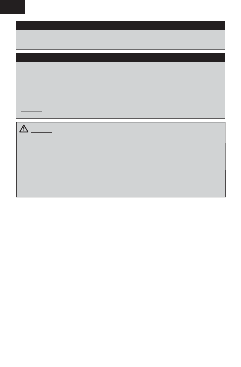
Specifi cations
56.0 in (1420mm)
Installed
BL 280 Outrunner Motor, 1260Kv
(EFLM7011)
BL Controller, 10A (EFLA7300BR)
AR6335 6-Channel AS3X
Receiver, Air (SPMAR6335)
(6) 3.5 g Digital Servo (EFLR7100)
29.9 in (760mm)
Need to Complete
12.5oz
(356 g)
To register your product online, go to www.e-fl iterc.com
450mAh 3S 11.1V 30C Li-Po, 18AWG
JST (EFLB4503SJ30)
Recommended Battery Charger:
Prophet™ Sport Plus 50W AC DC
Charger (DYNC2010CA)
Recommended Transmitter:
DSM2®/DSMX® technology with adjustable
dual rate and exponential (DX4e and up)
®
Nanolite
Full Range
3
Page 4
EN
Prefl ight Checklist
9
1. Charge fl ight battery.
2. Install fl ight battery in aircraft (once it has
been fully charged).
3. Bind aircraft to transmitter.
4. Make sure linkages move freely.
5. Perform Control Direction Test with
transmitter.
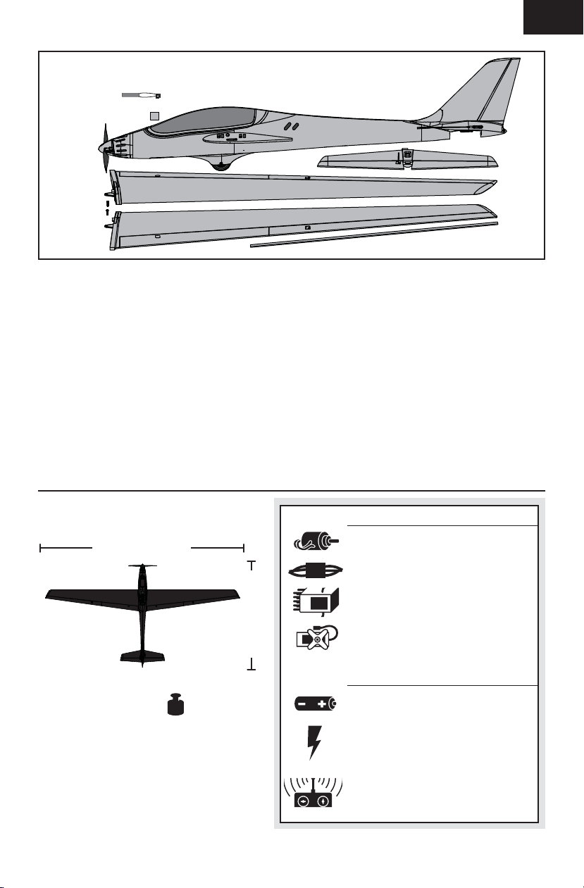
Wing Installation
1. Remove the canopy hatch before installing the
wings.
2. Slide the wing tube (A) into the fuselage.
3. Install the left and right wing (B and C) over
the wing tube and into the wing slot of the
fuselage while inserting the aileron and fl ap
servo connectors through the provided holes.
Tip: If needed, use hemostats or pliers to pull the
servo connectors into the fuselage.
CAUTION: DO NOT crush or otherwise
damage the wiring when attaching the wing
to the fuselage.
4. Connect the aileron servos from the wings to
the Y-harness connectors in the fuselage. The
left and right aileron servos can be connected
to either side of the Y-harness.
IMPORTANT: Correct operation of the AS3X system
requires connection of both ailerons to the included
Y-harness and the AILE channel of the receiver.
5. Connect the fl ap servos from the wings to
the Y-harness connectors in the fuselage. The
left and right fl ap servos can be connected to
either side of the Y-harness.
6. Secure the left and right wings to the fuselage
using the 2 included screws (D).
9
6. Adjust center of gravity.
7. Perform a radio system Range Check.
8. Find a safe and open area.
9. Plan fl ight for fl ying fi eld conditions.
Ailerons
B
A
C
Flaps
D
7. Replace the canopy on the fuselage.
When needed, disassemble in reverse order.
NOTICE: When disconnecting the servo connectors,
do not pull on the servo wires. Use a screwdriver
or pliers to break the friction fi t of the servo
connectors. Failure to do so could result in damage
to the servo wiring.
4
Page 5
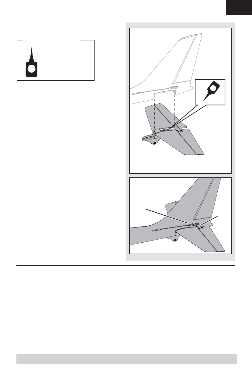
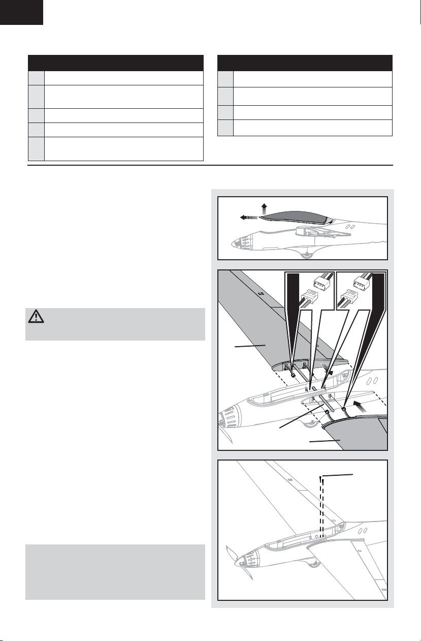
Horizontal Tail Installation
Required Adhesives:
Medium CA
1. Apply a small amount of CA (cyanoacrylate
adhesive) glue to the channel in the top of the
horizontal tail.
IMPORTANT: Keep glue away from the elevator
hinge.
2. Insert the tail wheel housing and the tail in the
slots in the rear of the fuselage.
3. Connect the elevator clevis (A) to the control
horn (B). Refer to the Control Horn and Servo
Arm Settings for correct connection.
EN
A
B
Low Voltage Cutoff (LVC)
When a Li-Po battery is discharged below 3V per cell, it will not hold a charge. The aircraft’s ESC protects
the fl ight battery from over-discharge using Low Voltage Cutoff (LVC). Once the battery discharges to 3V per
cell, the LVC will reduce the power to the motor in order to leave adequate power to the receiver and servos
to land the airplane.
When the motor power decreases, land the aircraft immediately and replace or recharge the fl ight battery.
Always disconnect and remove the Li-Po battery from the aircraft after each fl ight. Charge your Li-Po
battery to about half capacity before storage. Make sure the battery charge does not fall below 3V per cell.
Failure to unplug a connected battery will result in trickle discharge.
For your fi rst fl ights, set your transmitter timer or a stopwatch to 6 minutes. Adjust your timer for longer or
shorter fl ights once you have fl own the model. Flights of 10 minutes are achievable if using proper throttle
management.
NOTICE: Repeated fl ying to LVC will damage the battery.
5
Page 6
EN
Transmitter and Receiver Binding
Binding is the process of programming the receiver
to recognize the GUID (Globally Unique Identifi er)
code of a single specifi c transmitter. You need
to ‘bind’ your chosen Spektrum™ DSM2/DSMX
technology equipped aircraft transmitter to the
receiver for proper operation.
Any full range Spektrum DSM2/DSMX transmitter
can bind to the DSM2/DSMX receiver. Please visit
www.bindnfl y.com for a complete list of compatible
transmitters.
Important: Before binding a non-computerized
transmitter, ensure all servo reversing is set to
normal and trim is at center. Before binding a
computerized transmitter, choose a blank model
memory with only default (zero) settings. Select 1
aileron, 1 fl ap for the wing type.
Failure to do so could affect fl ight performance.
9 Binding Procedure
1. Refer to your transmitter’s unique instructions
for binding to a receiver (location of
transmitter’s Bind control).
2. Make sure the fl ight battery is disconnected
from the aircraft.
3. Power off the transmitter.
4. Bind the AR6335 receiver to a DSM2/DSMX
transmitter by inserting a bind plug in the bind
port of the receiver.
5. Connect the fl ight battery to the aircraft.
The receiver LED will begin to fl ash rapidly
(typically after 5 seconds).
6. Ensure that control surface trims are centered
and the throttle and throttle trims are in the
low position to correctly set the failsafe.
7. Put your transmitter into bind mode. Refer to
your transmitter’s manual for binding button or
switch instructions.
8. Keep the aircraft immobile out of the wind and,
after 5 to 10 seconds, the receiver status LED
will become solid, indicating that the receiver
is bound to the transmitter. If the LED does not
turn solid, refer to the Troubleshooting Guide at
the back of the manual.
9. Remove the bind plug from the receiver and
store it in a safe place. If the plug is diffi cult to
remove, carefully use pliers or a screwdriver to
overcome the friction fi t.
For subsequent fl ights, power on the transmitter
before connecting the fl ight battery.
CAUTION: When using a Futaba transmitter
with a Spektrum DSM® module, you must reverse
the throttle channel and rebind. Refer to your
Spektrum module manual for binding and failsafe
instructions. Refer to your Futaba transmitter
manual for instructions on reversing the throttle
channel.
BIND PLUG
6
Page 7

Battery Installation
1. Remove the canopy.
2. Apply the included loop tape to the bottom of
the battery.
3. Install the battery (A) in the battery cavity
towards the front of the fuselage. Refer to
the Center of Gravity instructions for the
battery’s position.
4. Connect the fully charged flight battery
to the ESC. Refer to the ESC Arming
instructions for correct connection of
the battery to the ESC.
5. Replace the canopy on the fuselage.
CAUTION: Always disconnect the Li-Po
battery from the ESC when not fl ying to avoid
over-discharging the battery. Batteries discharged
to a voltage lower than the lowest approved voltage
may become damaged, resulting in loss of
performance and potential fi re when batteries
are charged.
EN
A
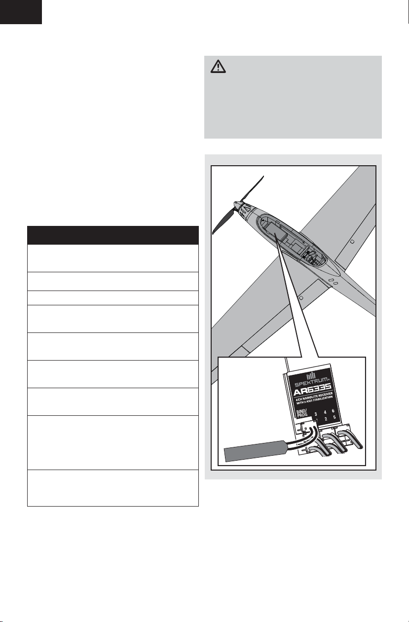
ESC Arming
Arming the ESC also occurs after binding as
previously described, but subsequent connection
of a fl ight battery requires the steps to the right.
Tip: If the ESC sounds a continuous double beep
after the fl ight battery is connected, recharge or
replace the battery.
If you accidentally connect the battery while the
throttle is opened or the throttle trim is high, a
musical tone will sound after 5 seconds and the
ESC will not arm until the throttle is returned to the
off position or the throttle trim is lowered.
CAUTION: Always keep hands away from
the propeller. When armed, the motor will turn
the propeller in response to any throttle
movement.
Lower throttle and
1
throttle trim to
lowest settings.
Power ON the
transmitter.
Remove the
2
2
canopy and install
the battery in the
battery cavity,
then connect the
battery to the ESC,
noting proper
polarity.
Keep the aircraft
3
3
immobile and
away form wind
for 5 seconds.
Series of tones
Continuous
receiver LED.
FLY...
7
Page 8

EN
Control Direction Test
Bind your aircraft and transmitter before doing these tests. Move the controls on the transmitter to make
sure the aircraft control surfaces move correctly and in the proper direction.
Always keep throttle at the low position during testing.
Make sure the tail linkages move freely and that paint or decals are not adhered to them.
Control Centering
Before the fi rst fl ights, or in the event of an
accident, make sure the fl ight control surfaces
are centered. Adjust the linkages mechanically if
the control surfaces are not centered.
1. Reset sub-trims to zero. Ensure the servo
arms are as perpendicular to the servo case as
possible. Use sub-trim to fine-tune as needed.
2. When an adjustment of linkages is needed, pull
the tube from the clevis to the linkage.
3. Carefully spread the clevis and adjust the
length of the linkage by screwing the clevis in
or out. Reattach the clevis in the proper hole in
the control horn.
4. Move the tube to tighten the clevis onto the
control horn.
Centering Controls After First Flights
For best performance with AS3X, it is important
that excessive trim is not used.
If the model requires excessive transmitter trim
(4 or more clicks of trim per channel), return the
transmitter trim to zero and adjust the linkages
mechanically so that the control surfaces are in the
fl ight trimmed position.
Control Horn and Servo Arm
Settings
This illustration shows the factory settings for
linkages on the control horns and servo arms.
After fl ying, you may choose to adjust the linkage
positions for the desired control response.
8
Horns Servo Arms
Elevator
Rudder
Ailerons
Flaps
Page 9

Dual Rates
EN
We recommend using a DSM2/DSMX radio
capable of dual rates. The settings to the right are
recommended starting settings for intermediate
pilots. Adjust according to individual preferences
after the initial fl ight.
Tip: For the fi rst fl ight, fl y the model at LOW RATE.
Center of Gravity (CG)
The CG location is 42–44mm back from the leading
edge of the wing at the wing root.
The battery compartment is oversized to allow for
Center of Gravity adjustment. Start by installing the
battery fully forward with the connectors facing the
front of the aircraft. Adjust as needed by sliding the
battery back.
High Rate Low Rate
Aileron 14mm / 10mm /
Elevator 8mm
Rudder 16mm
Dual Rates
Flaps
/ 6mm /
/ 12mm /
Half Full
15mm 30mm
42–44mm
9
Page 10

EN
Flying Tips and Repairs
Consult local laws and ordinances before
choosing a location to fl y your aircraft.
We recommend fl ying your aircraft outside in no
greater than moderate winds.
Always avoid fl ying near houses, trees, wires and
buildings. You should also be careful to avoid fl ying
in areas where there are many people, such as busy
parks, schoolyards or soccer fi elds.
Range Check Your Radio System
After fi nal assembly, range check the radio system
with the aircraft. Refer to your specifi c transmitter
and receiver instruction manuals for range test
information.
Flying
This motor glider is capable of aerobatics, such as
loops and rolls. However, avoid prolonged, steep
dives. Manage the energy of descent without going
top speed.
Hand Launching
When hand-launching your aircraft alone, hold the
aircraft in one hand and the transmitter in the other.
Apply about 1/2–3/4 throttle. Hold the aircraft on
the underside and throw the aircraft directly into the
wind, angled slightly up (5 to 10 degrees above the
horizon). Climb to check the trim. Once the trim is
adjusted, begin exploring the fl ight envelope of the
aircraft.
Soaring
Your aircraft can ascend on thermals and other
updrafts to prolong its fl ight. There are many ways
to stay aloft with a sailplane, such as ridge lifts and
thermals.
A thermal is simply a column of rising warm air.
Once you get your aircraft into the air, watch your
aircraft for a response to thermals. If the airplane
randomly rolls on its own, it is likely that you only
fl ew through the edge of the thermal, causing one
side of the airplane to rise, rather than the entire
airplane. Enter the thermal by turning your aircraft
directly into it, circling to stay in the center of the
thermal. Slow your forward speed by increasing
up elevator trim so that your aircraft is moving just
faster than stall (minimum sink speed). Make easy
banking turns to fi nd the area of highest lift (the
thermal’s core).
When you fi nd the core of lift, tighten your turns to
stay near this position. Sometimes thermals drift
downwind. It is best that you search for thermals
upwind, so that you can follow a thermal downwind
if it is pushed downwind. With practice, you will fi nd
it easier to locate and anticipate the movement of
thermals. Although thermals cannot be seen, you
can see dust, insects or birds riding an updraft. Air
movement of a thermal may be felt, so movement in
an otherwise calm spot may show you the location
of a nearby thermal. A shift in the wind (in a light
breeze) can be airfl ow into a thermal.
Flaps
During landing, the fl aps allow a landing approach
to be steeper because of the increased drag. Flaps
make the aircraft come in at a slower airspeed and
make it easier to fl are and settle in for a smooth
landing.
Landing
Make sure to land on a soft surface, like grass. Fly
the aircraft into the wind approximately 36 inches
(90cm) or less above the surface. During fl are,
keep the wings level and the aircraft pointed into
the wind. Gently pull back on the elevator to bring
the aircraft down on its main wheel. Fully lower
the throttle just before the aircraft lands to avoid
propeller damage.
NOTICE: If a crash is imminent, reduce the throttle
fully. Failure to do so could result in extra damage
to the airframe, as well as damage to the ESC and
motor.
NOTICE: Crash damage is not covered under
warranty.
Repairs
Repair this aircraft using CA (cyanoacrylate
adhesive) glue or clear tape.
When parts are not repairable, see the Replacement
Parts List for ordering by item number.
For a listing of all replacement and optional parts,
refer to the list at the back of this manual.
NOTICE: Use of CA accelerant on your aircraft can
damage paint. DO NOT handle the aircraft until
accelerant fully dries.
NOTICE: When you are fi nished fl ying, never leave
the aircraft in direct sunlight or in a hot, enclosed
area such as a car. Doing so can damage the foam.
10
Page 11

Post Flight Checklist
EN
9
1. Disconnect fl ight battery from ESC
(Required for safety and battery life).
2. Power off transmitter.
3. Remove fl ight battery from aircraft.
4. Recharge fl ight battery.
Service of Power Components
Disassembly
CAUTION: Always disconnect the battery
before handling or adjusting the propeller
or motor. Failure to do so could result in
personal injury.
Propeller
1. Remove the 2 screws (A) from the spinner (B).
Carefully separate the spinner from the back
plate.
2. Remove 2 bolts (C), 2 nuts (D) and 2 propeller
blades (E) from the back plate.
3. Remove the lock nut (F) from the propeller
shaft, then remove the back plate (G).
4. Loosen the 2 setscrews (H) and remove the
propeller shaft (I) from the motor.
Motor and Firewall
9
5. Store fl ight battery apart from aircraft
and monitor the battery charge.
6. Make note of fl ight conditions and fl ight
plan results, planning for future fl ights.
D
A BCE
B
L
F GI
M
1. Remove the 4 screws (J) and motor mount (K)
from the fuselage.
2. Disconnect the motor wires from the ESC.
3. Loosen the 2 setscrews (L) and remove the
motor (M) from the motor mount.
Assemble in reverse order.
Assembly Tips
• Correctly align and connect the motor wire
colors with the ESC wires.
• Ensure the propeller blades swing freely in the
spinner back plate.
• Tools are required to loosen or tighten the
setscrews and the lock nut.
• Ensure the spinner is fully connected to the
spinner back plate for safe operation.
JKH
11
Page 12

EN
Troubleshooting Guide
Problem Possible Cause Solution
Aircraft will not
respond to throttle
but responds to
other controls
Extra propeller
noise or extra
vibration
Reduced fl ight
time or aircraft
underpowered
Aircraft will not
Bind (during
binding) to
transmitter
Aircraft will not
connect (after
binding) to
transmitter
Control surface
does not move
Controls reversed Transmitter settings reversed Adjust controls on transmitter appropriately
Motor power
quickly decreases
and increases then
motor loses power
ESC did not arm because throttle stick and/or
throttle trim too high
Throttle channel is reversed Reverse throttle channel on transmitter
Motor disconnected from ESC Make sure motor is connected to the ESC
Servo travel setup is less than 100% Adjust servo travel to 100% or slightly
Damaged propeller, spinner or motor Replace damaged parts
Prop nut is too loose Tighten the prop nut
Prop is out of balance Remove and balance propeller, or replace
Spinner is not tight or fully seated in place Tighten the spinner or remove the spinner
Flight battery charge is low Completely recharge fl ight battery
Propeller installed incorrectly Install propeller properly
Flight battery damaged Replace fl ight battery and follow fl ight
Flight battery is too cold Make sure battery is warm before use
Battery capacity too low for power drawn Replace battery or use a larger capacity
Transmitter too near aircraft during binding
process
Bind switch or button not held long enough
during bind process
Flight battery/Transmitter battery charge is too
low
The bind plug is not installed correctly in the
bind port
Aircraft or transmitter is too close to large metal
object, wireless source or another transmitter
Transmitter too close to aircraft during
connecting process
Flight battery/Transmitter battery charge is too
low
Aircraft bound to different model memory
(ModelMatch™ radios only)
Transmitter may have been bound to a different
aircraft using different DSM protocol
Bind plug left installed in bind port Rebind transmitter to the aircraft and
Aircraft or transmitter is too close to large metal
object, wireless source or another transmitter
Control surface, control horn, linkage or
servo damage
Servo wire damaged or connections loose Do a check of wires and connections,
Flight battery charge is low Fully recharge fl ight battery
Control linkage does not move freely Make sure control linkage moves freely
Battery voltage is down to the point of receiver/
ESC Low Voltage Cutoff (LVC)
Lower throttle stick and throttle trim to
lowest setting
greater
with a balanced propeller
and turn it 180 degrees
battery instructions
battery
Power off transmitter, move transmitter a
larger distance from aircraft, disconnect and
reconnect fl ight battery to aircraft and follow
binding instructions
Power off transmitter and repeat bind
process. Hold transmitter bind button or
switch until receiver is bound
Replace/recharge batteries
Install bind plug in bind port and bind the
aircraft to the transmitter
Move aircraft and transmitter to another
location and attempt binding again
Power off transmitter, move transmitter a
larger distance from aircraft, disconnect and
reconnect fl ight battery to aircraft
Replace/recharge batteries
Select correct model memory on transmitter
Bind aircraft to transmitter
remove the bind plug before cycling power
Move aircraft and transmitter to another
location and attempt connecting again
Replace or repair damaged parts and adjust
controls
connect or replace as needed
Recharge fl ight battery or replace battery
that is no longer performing
12
Page 13

Limited Warranty
What this Warranty Covers
Horizon Hobby, LLC (“Horizon”) warrants to the original
purchaser that the product purchased (the “Product”) will
be free from defects in materials and workmanship at the
date of purchase.
What is Not Covered
This warranty is not transferable and does not cover
(i) cosmetic damage, (ii) damage due to acts of God,
accident, misuse, abuse, negligence, commercial
use, or due to improper use, installation, operation or
maintenance, (iii) modifi cation of or to any part of the
Product, (iv) attempted service by anyone other than
a Horizon Hobby authorized service center, (v) Product
not purchased from an authorized Horizon dealer, or
(vi) Product not compliant with applicable technical
regulations.
OTHER THAN THE EXPRESS WARRANTY ABOVE, HORIZON
MAKES NO OTHER WARRANTY OR REPRESENTATION, AND
HEREBY DISCLAIMS ANY AND ALL IMPLIED WARRANTIES,
INCLUDING, WITHOUT LIMITATION, THE IMPLIED WARRANTIES OF NON-INFRINGEMENT, MERCHANTABILITY AND
FITNESS FOR A PARTICULAR PURPOSE. THE PURCHASER
ACKNOWLEDGES THAT THEY ALONE HAVE DETERMINED
THAT THE PRODUCT WILL SUITABLY MEET THE REQUIREMENTS OF THE PURCHASER’S INTENDED USE.
Purchaser’s Remedy
Horizon’s sole obligation and purchaser’s sole and
exclusive remedy shall be that Horizon will, at its option,
either (i) service, or (ii) replace, any Product determined
by Horizon to be defective. Horizon reserves the right to
inspect any and all Product(s) involved in a warranty claim.
Service or replacement decisions are at the sole discretion
of Horizon. Proof of purchase is required for all warranty
claims. SERVICE OR REPLACEMENT AS PROVIDED
UNDER THIS WARRANTY IS THE PURCHASER’S SOLE AND
EXCLUSIVE REMEDY.
Limitation of Liability
HORIZON SHALL NOT BE LIABLE FOR SPECIAL, INDIRECT,
INCIDENTAL OR CONSEQUENTIAL DAMAGES, LOSS OF
PROFITS OR PRODUCTION OR COMMERCIAL LOSS IN ANY
WAY, REGARDLESS OF WHETHER SUCH CLAIM IS BASED
IN CONTRACT, WARRANTY, TORT, NEGLIGENCE, STRICT
LIABILITY OR ANY OTHER THEORY OF LIABILITY, EVEN IF
HORIZON HAS BEEN ADVISED OF THE POSSIBILITY OF
SUCH DAMAGES. Further, in no event shall the liability
of Horizon exceed the individual price of the Product on
which liability is asserted. As Horizon has no control over
use, setup, fi nal assembly, modifi cation or misuse, no
liability shall be assumed nor accepted for any resulting
damage or injury. By the act of use, setup or assembly, the
user accepts all resulting liability. If you as the purchaser
or user are not prepared to accept the liability associated
with the use of the Product, purchaser is advised to return
the Product immediately in new and unused condition to
the place of purchase.
Law
These terms are governed by Illinois law (without regard to
confl ict of law principals). This warranty gives you specifi c
legal rights, and you may also have other rights which vary
from state to state. Horizon reserves the right to change or
modify this warranty at any time without notice.
WARRANTY SERVICES
Questions, Assistance, and Services
Your local hobby store and/or place of purchase cannot
provide warranty support or service. Once assembly, setup
EN
or use of the Product has been started, you must contact
your local distributor or Horizon directly. This will enable
Horizon to better answer your questions and service
you in the event that you may need any assistance. For
questions or assistance, please visit our website at www.
horizonhobby.com, submit a Product Support Inquiry,
or call the toll free telephone number referenced in the
Warranty and Service Contact Information section to speak
with a Product Support representative.
Inspection or Services
If this Product needs to be inspected or serviced and is
compliant in the country you live and use the Product in,
please use the Horizon Online Service Request submission
process found on our website or call Horizon to obtain a
Return Merchandise Authorization (RMA) number. Pack
the Product securely using a shipping carton. Please
note that original boxes may be included, but are not
designed to withstand the rigors of shipping without
additional protection. Ship via a carrier that provides
tracking and insurance for lost or damaged parcels, as
Horizon is not responsible for merchandise until it arrives
and is accepted at our facility. An Online Service Request
is available at http://www.horizonhobby.com/content/_
service-center_render-service-center. If you do not have
internet access, please contact Horizon Product Support
to obtain a RMA number along with instructions for
submitting your product for service. When calling Horizon,
you will be asked to provide your complete name, street
address, email address and phone number where you can
be reached during business hours. When sending product
into Horizon, please include your RMA number, a list of
the included items, and a brief summary of the problem.
A copy of your original sales receipt must be included
for warranty consideration. Be sure your name, address,
and RMA number are clearly written on the outside of the
shipping carton.
NOTICE: Do not ship LiPo batteries to Horizon. If you
have any issue with a LiPo battery, please contact the
appropriate Horizon Product Support offi ce.
Warranty Requirements
For Warranty consideration, you must include your
original sales receipt verifying the proof-of-purchase
date. Provided warranty conditions have been met, your
Product will be serviced or replaced free of charge.
Service or replacement decisions are at the sole discretion
of Horizon.
Non-Warranty Service
Should your service not be covered by warranty,
service will be completed and payment will be
required without notifi cation or estimate of the
expense unless the expense exceeds 50% of the retail
purchase cost. By submitting the item for service you are
agreeing to payment of the service without notifi cation.
Service estimates are available upon request. You must
include this request with your item submitted for service.
Non-warranty service estimates will be billed a minimum
of ½ hour of labor. In addition you will be billed for return
freight. Horizon accepts money orders and cashier’s
checks, as well as Visa, MasterCard, American Express,
and Discover cards. By submitting any item to Horizon
for service, you are agreeing to Horizon’s Terms and
Conditions found on our website http://www.horizonhobby.
com/content/_service-center_render-service-center.
ATTENTION: Horizon service is limited to Product
compliant in the country of use and ownership.
13
Page 14

EN
If received, a non-compliant Product will not be
serviced. Further, the sender will be responsible for
arranging return shipment of the un-serviced Product,
through a carrier of the sender’s choice and at the
sender’s expense. Horizon will hold non-compliant
Product for a period of 60 days from notifi cation, after
which it will be discarded.
Warranty and Service Contact Information
Country of
Purchase
United
States of
America
United
Kingdom
Germany
France
China
Horizon Hobby Phone Number/Email Adress Address
Horizon Service Center
(Repairs and Repair Requests)
Horizon Product Support
(Product Technical Assistance)
Sales
Service/Parts/Sales:
Horizon Hobby Limited
Horizon Technischer Service
Sales: Horizon Hobby GmbH
Service/Parts/Sales:
Horizon Hobby SAS
Service/Parts/Sales:
Horizon Hobby – China
servicecenter.horizonhobby.
com/RequestForm/
www.quickbase.com/db/
bghj7ey8c?a=GenNewRecord
888-959-2305
sales@horizonhobby.com
888-959-2305
sales@horizonhobby.co.uk
+44 (0) 1279 641 097
service@horizonhobby.de
+49 (0) 4121 2655 100
infofrance@horizonhobby.com
+33 (0) 1 60 18 34 90
info@horizonhobby.com.cn
+86 (021) 5180 9868
4105 Fieldstone Rd
Champaign, Illinois
61822 USA
Units 1–4 , Ployters Rd,
Staple Tye Harlow, Essex,
CM18 7NS, United Kingdom
Christian-Junge-Straße 1
25337 Elmshorn, Germany
11 Rue Georges Charpak
77127 Lieusaint, France
Room 506,
No. 97 Changshou Rd.
Shanghai, China 200060
FCC Information
Operation is subject to the following two conditions: (1)
This device may not cause harmful interference, and
(2) this device must accept any interference received,
including interference that may cause undesired operation.
CAUTION: Changes or modifi cations not expressly
approved by the party responsible for compliance could
void the user’s authority to operate the equipment.
This product contains a radio transmitter with wireless
technology which has been tested and found to be
compliant with the applicable regulations governing a
radio transmitter in the 2.400GHz to 2.4835GHz frequency
range.
IC Information
This device complies with Industry Canada licenceexempt RSS standard(s). Operation is subject to the
following two conditions: (1) this device may not
cause interference, and (2) this device must accept
any interference, including interference that may
cause undesired operation of the device.
Compliance Information for the European Union
Declaration of Conformity
(in accordance with ISO/IEC 17050-1)
No. HH2014060601
Product(s): Adagio 280 BNF Basic
Item Number(s): EFL6550
Equipment class: 1
The object of declaration described above is in conformity
with the requirements of the specifi cations listed below,
following the provisions of the European R&TTE directive
1999/5/EC and EMC Directive 2004/108/EC:
EN 301 489-1 V1.9.2: 2012
EN 301 489-17 V2.1.1: 2009
EN55022:2010 + AC:2011
EN55024:2010
Signed for and on behalf of:
Horizon Hobby, LLC
Champaign, IL USA
Jun 6, 2014
14
Chief Financial Offi cer
Rober Peak
Horizon Hobby, LLC
Instructions for disposal of WEEE by
users in the European Union
This product must not be disposed
of with other waste. Instead, it is the
user’s responsibility to dispose of their
waste equipment by handing it over
to a designated collections point for
the recycling of waste electrical and electronic
equipment. The separate collection and recycling
of your waste equipment at the time of disposal
will help to conserve natural resources and ensure
that it is recycled in a manner that protects human
health and the environment. For more information
about where you can drop off your waste equipment
for recycling, please contact your local city offi ce,
your household waste disposal service or where you
purchased the product.
Page 15

Replacement Parts – Ersatzteile –
– Pièces de rechange – Pezzi di ricambio –
Part # • Nummer
Numéro • Codice
EFL6501
EFL6502
EFL6503
EFL6504
EFL6505
EFL6520
EFL6567
EFLA7300BR
EFLR7100
EFLM7011
SPMAR6335
EFL635012
EFLR710001
EFLR710002
Description Beschreibung Description Descrizione
Horizontal Stab:
Adagio 280
Hatch: Adagio
280
Prop and Spinner: Adagio 280
Pushrods/Horns:
Adagio 280
Wing Tube:
Adagio 280
Wing Set: Adagio
280
Fuselage: Adagio
280
10-Amp Brushless ESC
3.5 g Digital
Sub-Micro Servo
BL 280 Outrunner Motor,
1260Kv
AR6335 6-Channel AS3X Nanolite Receiver
Motor Shaft:
Inverza 280 BNF
Gear Set:
EFLR7100
Servo Arm Set:
EFLR7100
E-fl ite Adagio 280:
Höhenleitwerk m. Rad
E-fl ite Adagio 280:
Haube
E-fl ite Adagio 280:
Klapp-Propeller u.
Spinner
E-fl ite Adagio 280:
Ruderhörner u. Gestänge
E-fl ite Adagio 280:
Tragfl ächenverbinder
E-fl ite Adagio 280:
Tragfl ächenset
E-fl ite Adagio 280:
Rumpf m. Rad
E-fl ite 10-Amp Brushless ESC
E-fl ite 3.5g Digital Servo Sub-micro servo
E-fl ite BL 280 Außenläufer Motor 1260Kv
Spektrum 6 Kanal Nanolite Empfänger AS3X
E-fl ite Inverza 280 BNF :
Motorwelle
E-fl ite Getriebe Set:
EFLR7100
E-fl ite Servo Arm Set:
EFLR7100
Horizontal
Stabilisateur: Adagio
280
Trappe: Adagio 280 Portello: Adagio 280
Cône avec hélice:
Adagio 280
Tringlerie et guignols:
Adagio 280
Clé d’aile: Adagio 280 Tubo ala: Adagio 280
Aile: Adagio 280 Set ala: Adagio 280
Fuselage: Adagio 280 Fusoliera: Adagio 280
Contrôleur brushless
10A
digital 3.5g
Moteur BL 280 à cage
tournante, 1260Kv
Récepteur AR6335
AS3X Nanolite 6 voies
Axe moteur : Inverza
280 BNF
Jeu de pignons :
EFLR7100
Set de bras de servo :
EFLR7100
Stabilizzatore
orizzontale: Adagio 280
Elica e ogiva: Adagio
280
Rinvii/Squadrette:
Adagio 280
Regolatore (ESC)
brushless 10A
Servo digitale submicro
da 3,5g
BL 280 motore a cassa
rotante, 1260Kv
AR6335 AS3XRicevitore Nanolite a 6 canali
Albero motore: Inverza
280 BNF
Set ingranaggi:
EFLR7100
Set squadrette servi:
EFLR7100
54
Page 16

– Optional Parts and Accessories –
– Optionale Bauteile und Zubehörteile –
– Pièces optionnelles et accessoires –
– Parti opzionali e accessori –
Part # • Nummer
Numéro • Codice
EFLA230
EFLA250
DYN2803
DYN2815
DYN2820
EFLB4503SJ50
EFLB4503SJ30
EFLB4303SJ
DYNC2010CA
EFLA1010
Description Beschreibung Description Descrizione
Charger Lead with
JST Female
Park Flyer Tool
Assortment, 5 pc
Nut Driver: 5.5mm Steckschlüssel
Hex Driver: 2mm Dynamite
Hex Driver: .050” Dynamite
450mAh 3S 11.1V
50C Li-Po, 18AWG
JST
450mAh 3S 11.1V
30C Li-Po, 18AWG
JST
430mAh 3S 11.1V
20C LiPo,20AWG JST
Prophet Sport Plus
50W AC DC Charger
10-Amp Pro Brushless
ESC
DX4e DSMX
4-Channel Transmitter
DX5e DSMX
5-Channel Transmitter
DX6i DSMX
6-Channel Transmitter
DX6 DSMX
6-Channel Transmitter
DX7s DSMX
7-Channel Transmitter
DX8 DSMX 8-Channel
Transmitter
DX9 DSMX 9-Channel
Transmitter
DX18 DSMX18 Channel Transmitter
E-fl ite Ladekabel m/
JST Buchse
Park Flyer
Werkzeugsortiment,
5 teilig
5.5mm
Inbusschlüssel 2mm
metrisch
Inbusschlüssel ,050
450mAh 3S 11.1V
50C Li-Po, 18AWG
JST Akku
450mAh 3S 11.1V
30C Li-Po, 18AWG
JST Akku
430mAh 3S 11.1V
20C LiPo- Akku JST
Dynamite Ladegerät
Prophet Sport Plus
50W AC/DC EU
E-fl ite 10-Amp Pro
Brushless Regler
DX4e DSMX
4-Kanal Sender
DX5e DSMX
5-Kanal Sender
DX6i DSMX
6-Kanal Sender
DX6 DSMX
6-Kanal Sender
Spektrum DX7s
7 Kanal Sender
Spektrum DX8 nur
Sender
Spektrum DX9 nur
Sender
Spektrum DX18 nur
Sender
Câble de charge avec
prise JST femelle
Assortiment d’outils
park fl yer, 5pc
Clé à écrou 5.5mm Chiave per dadi:
Clé BTR 2mm Chiave esagonale:
Clé BTR .050” Chiave esagonale:
Batterie Li-Po 11.1V
3S 450mA 50C,
18AWG JST
Batterie Li-Po 11.1V
3S 450mA 30C,
18AWG JST
Li-Po 11.1V 3S
430mA 20C, prise JST
Chargeur Prophet
Sport Plus 50W AC DC
Contrôleur brushless
10A pro
Emetteur DX4e
DSMX 4 voies
Emetteur DX5e
DSMX 5 voies
Emetteur DX6i
DSMX 6 voies
Emetteur DX6
DSMX 6 voies
Emetteur DX7s DSMX
7 voies
Emetteur DX8 DSMX
8 voies
Emetteur DX9 DSMX
9 voies
Emetteur DX18 DSMX
18 voies
Cavo di carica con
femmina JST
Park Flyer
assortimento
attrezzi, 5 pc
5.5mm
2mm
.050”
Batteria Li-
Po450mAh 3S 11.1V
50C, 18AWG JST
Batteria LiPo450mAh 3S 11.1V
30C, 18AWG JST
430mAh 3S 11.1V
20C LiPo,20AWG JST
Caricabatterie
Prophet Sport Plus
50W AC DC
ESC 10-Amp Pro
Brushless
DX4e DSMX
Trasmettitore 4 canali
DX5e DSMX
Trasmettitore 5 canali
DX6i DSMX
Trasmettitore 6 canali
DX6 DSMX
Trasmettitore 6 canali
DX7s DSMX
Trasmettitore 7
canali
DX8 DSMX
trasmettitore 8 canali
DX9 DSMX
trasmettitore 9 canali
DX18 DSMX
trasmettitore 18
canali
55
Page 17

© 2014 Horizon Hobby, LLC.
E-fl ite, Adagio, Prophet, DSM, DSM2, DSMX, AS3X, ModelMatch, and the BNF logo are trademarks
or registered trademarks of Horizon Hobby, LLC.
The Spektrum trademark is used with permission of Bachmann Industries, Inc.
The trim scheme of the Adagio was designed by Mirco Pecorari of Aircraft Studio Design.
Futaba is a registered trademark of Futaba Denshi Kogyo Kabushiki Kaisha
Corporation of Japan.
Patents pending.
www.e-fl iterc.com
EFL6550
Created 05/14 44366
 Loading...