

Page 1
A6M5 Zero 300
Instruction Manual
Bedienungsanleitung
Manuel d’utilisation
Manuale di Istruzioni
Page 2

EN
NOTICE
All instructions, warranties and other collateral documents are subject to change at the sole discretion
of Horizon Hobby, Inc. For up-to-date product literature, visit www.horizonhobby.com and click on the
support tab for this product.
Meaning of Special Language:
The following terms are used throughout the product literature to indicate various levels of potential
harm when operating this product:
NOTICE: Procedures, which if not properly followed, create a possibility of physical property damage AND
little or no possibility of injury.
CAUTION: Procedures, which if not properly followed, create the probability of physical property damage
AND a possibility of serious injury.
WARNING: Procedures, which if not properly followed, create the probability of property damage,
collateral damage, and serious injury OR create a high probability of superfi cial injury.
WARNING: Read the ENTIRE instruction manual to become familiar with the features of the
product before operating. Failure to operate the product correctly can result in damage to the product,
personal property and cause serious injury.
This is a sophisticated hobby product. It must be operated with caution and common sense and requires
some basic mechanical ability. Failure to operate this product in a safe and responsible manner could
result in injury or damage to the product or other property. This product is not intended for use by
children without direct adult supervision. Do not use with incompatible components or alter this product
in any way outside of the instructions provided by Horizon Hobby, Inc. This manual contains instructions
for safety, operation and maintenance. It is essential to read and follow all the instructions and warnings
in the manual, prior to assembly, setup or use, in order to operate correctly and avoid damage or serious
injury.
Age Recommendation: Not for children under
14 years. This is not a toy.
Safety Precautions and Warnings
• Always keep a safe distance in all directions
around your model to avoid collisions or injury.
This model is controlled by a radio signal subject
to interference from many sources outside your
control. Interference can cause momentary loss
of control.
• Always operate your model in open spaces away
from full-size vehicles, traffi c and people.
• Always carefully follow the directions and
warnings for this and any optional support equipment (chargers, rechargeable battery packs, etc.).
• Always keep all chemicals, small parts and
anything electrical out of the reach of children.
• Always avoid water exposure to all equipment
not specifi cally designed and protected for this
purpose. Moisture causes damage to electronics.
2
• Never place any portion of the model in your
mouth as it could cause serious injury or even
death.
• Never operate your model with low transmitter
batteries.
• Always keep aircraft in sight and under control.
• Always use fully charged batteries.
• Always keep transmitter powered on while
aircraft is powered.
• Always remove batteries before disassembly.
• Always keep moving parts clean.
• Always keep parts dry.
• Always let parts cool after use before touching.
• Always remove batteries after use.
• Always ensure failsafe is properly set
before fl ying.
• Never operate aircraft with damaged wiring.
• Never touch moving parts.
Page 3
Thank you for purchasing the E-fl ite® A6M5 Zero 300 BNF-Basic. E-fl ite has captured the character of the
infamous Japanese WWII fi ghter in a fun-to-fl y RC warbird modeled after Zeros stationed at the Genzan Air
Base in Korea in 1945. Molded in a smooth and durable foam material, its outline, detail and markings have
been faithfully duplicated and very few design liberties were taken to achieve excellent fl ight performance.
This allows the stunning scale appearance to shine through both on the ground and in fl ight. In fact, the
fi t and fi nish of this electric powered, 4-channel warbird is so impeccable that it can also serve as an
impressive display model when mounted on the included static display stand. Please be sure to read
through this manual carefully so that you can successfully enjoy all the benefi ts this outstanding E-fl ite
model has to offer.
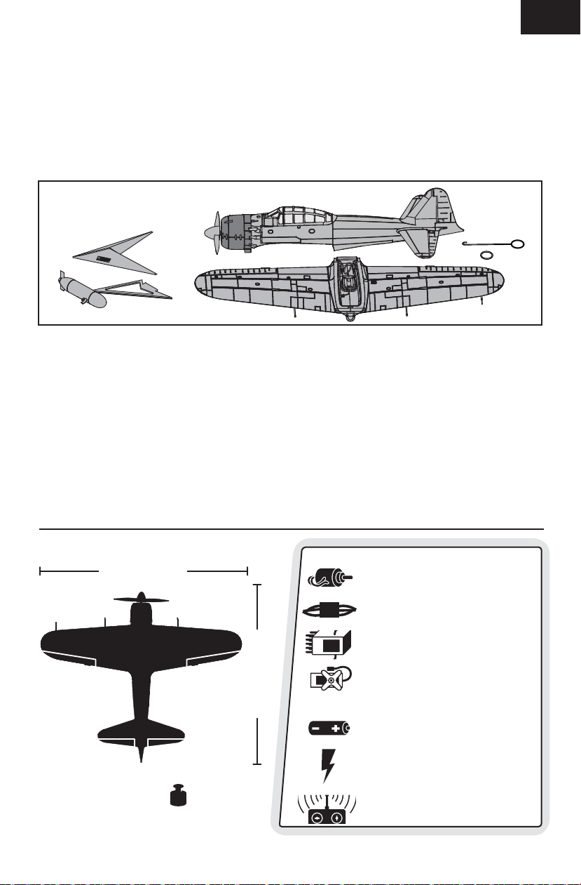
Box Contents
Table of Contents
Prefl ight Checklist ................................................... 4
Transmitter and Receiver Binding ...........................4
Low Voltage Cutoff (LVC) .........................................4
Installing the Flight Battery ....................................5
Arming the ESC ......................................................5
Installing the Wing ..................................................6
Control Centering .................................................... 7
Settings for Control Horns .......................................7
Control Direction Test .............................................7
Dual Rates and Expos .............................................8
Adjusting Center of Gravity (CG) ..............................8
Flying Tips and Repairs ........................................... 9
Using the Display Stand ........................................10
Service of Power Components ..............................11
Troubleshooting Guide ..........................................12
Limited Warranty ..................................................13
Warranty and Service Information .........................14
Compliance Information for the European Union .... 14
Replacement Parts ................................................ 54
Optional Parts and Accessories .............................55
Parts Contact Information .....................................55
EN
25.5 in (650mm)
To register your product online, go to www.e-fl iterc.com
8.20–8.70 oz
(232–246 g)
21.6 in (550mm)
Installed
Motor: BL300 Brushless Outrunner,
1400Kv (EFLM7000)
BL Controller, 10A (EFLA7300)
AR6310 DSMX Nanolite 6Ch Rx,Air
(SPMAR6310)
(3) 3.5 g Digital Servo (EFLR7100)
Needed to Complete
Recommended Battery: 430mAh 2S
20C Li-Po (EFLB4302SJ)
Recommended Battery Charger:
™
Celectra
Battery Charger (EFLC3025)
Recommended Transmitter:
Full Range DSM2®/DSMX® (DX4e and up)
80W AC/DC Multi-Chemistry
3
Page 4
EN
Prefl ight Checklist
9
1. Charge fl ight battery.
2. Install fl ight battery in aircraft
(once it has been fully charged).
3. Bind aircraft to transmitter.
4. Make sure linkages move freely.
5. Perform Control Direction Test with
transmitter.
6. Adjust center of gravity.
7. Perform a radio system Range Check.
8. Find a safe and open area.
9. Plan fl ight for fl ying fi eld conditions.
Low Voltage Cutoff (LVC)
When a Li-Po battery is discharged below 3V per
cell, it will not hold a charge. The aircraft’s ESC
protects the fl ight battery from over-discharge
using Low Voltage Cutoff (LVC). Once the battery
discharges to 3V per cell, the LVC will reduce the
power to the motor in order to leave adequate power
to the receiver and servos to land the airplane.
When the motor power reduces, land the aircraft
immediately and replace or recharge the
fl ight battery.
Always disconnect and remove the Li-Po battery
from the aircraft after each fl ight. Charge your
Li-Po battery to about half capacity before storage.
Make sure the battery charge does not fall below
3V per cell. A connected battery will result in trickle
discharge.
For your fi rst fl ights, set your transmitter timer or a
stopwatch to 4 minutes. Adjust your timer for longer
or shorter fl ights once you have fl own the model.
Flights of 6 minutes or more are achievable if using
proper throttle management.
NOTICE: Repeated fl ying to LVC will damage
the battery.
Transmitter and Receiver Binding
Binding is the process of programming the receiver of the control unit to recognize the GUID (Globally
Unique Identifi er) code of a single specifi c transmitter. You need to ‘bind’ your chosen SpektrumTM DSM2
®
DSMX
technology equipped aircraft transmitter to the receiver for proper operation.
Any full range Spektrum DSM2/DSMX transmitter can bind to the DSM2/DSMX receiver. Please visit www.
bindnfl y.com for a complete list of compatible transmitters.
NOTICE: When using a Futaba
is required.
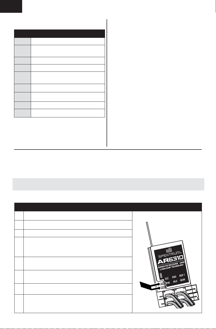
Binding Procedure
9
1. Refer to your transmitter’s unique instructions for binding to
a receiver (location of transmitter’s Bind control).
2. Make sure the fl ight battery is disconnected from the
aircraft.
3. Power off the transmitter.
4. Bind the AR6310 receiver to a DSM2 transmitter by shorting
the bind pins (A) together with tweezers, a hemostat or
small needle-nose pliers. Metal to metal contact is needed to
complete the circuit. Do not bend the bind pins.
5. Connect the fl ight battery to the aircraft. Short the pins until
the receiver LED begins to fl ash rapidly (typically after 5
seconds).
6. Ensure that control surface trims are centered and the
throttle and throttle trim are in the low position to correctly
set failsafe.
7. Put your transmitter into bind mode. Refer to your transmitter’s manual for binding button or switch instructions.
8. After 5 to 10 seconds, the receiver status LED will become
solid, indicating that the receiver is bound to the transmitter.
If the LED does not turn solid, refer to the Troubleshooting
Guide at the back of the manual.
4
®
transmitter with a Spektrum DSM module, reversing the throttle channel
A
®
/
Page 5
Installing the Flight Battery
1. Remove the canopy by gripping near the rear
and pulling up, then back to disengage the
canopy’s front tab from the fuselage.
2. Place the flight battery in the battery
compartment. Slide the battery into the battery
cavity (A) towards the front of the fuselage.
See the Adjusting the Center of Gravity
instructions for the battery’s position.
3. Connect the fully charged flight battery to
the ESC connector. See the Arming the ESC
instructions for correct connection of the
battery to the ESC.
4. Replace the canopy on the fuselage.
CAUTION: Always disconnect the Li-Po
battery from the ESC when not fl ying to eliminate
power supplied to the motor. The ESC does not have
an arming switch, and will respond to any
transmitter input when a signal is present.
EN
CAUTION: Always disconnect the Li-Po
battery from the ESC when not fl ying to avoid
over-discharging the battery. Batteries discharged
to a voltage lower than the lowest approved voltage
may become damaged, resulting
in loss of performance and potential fi re when
batteries are charged.
A
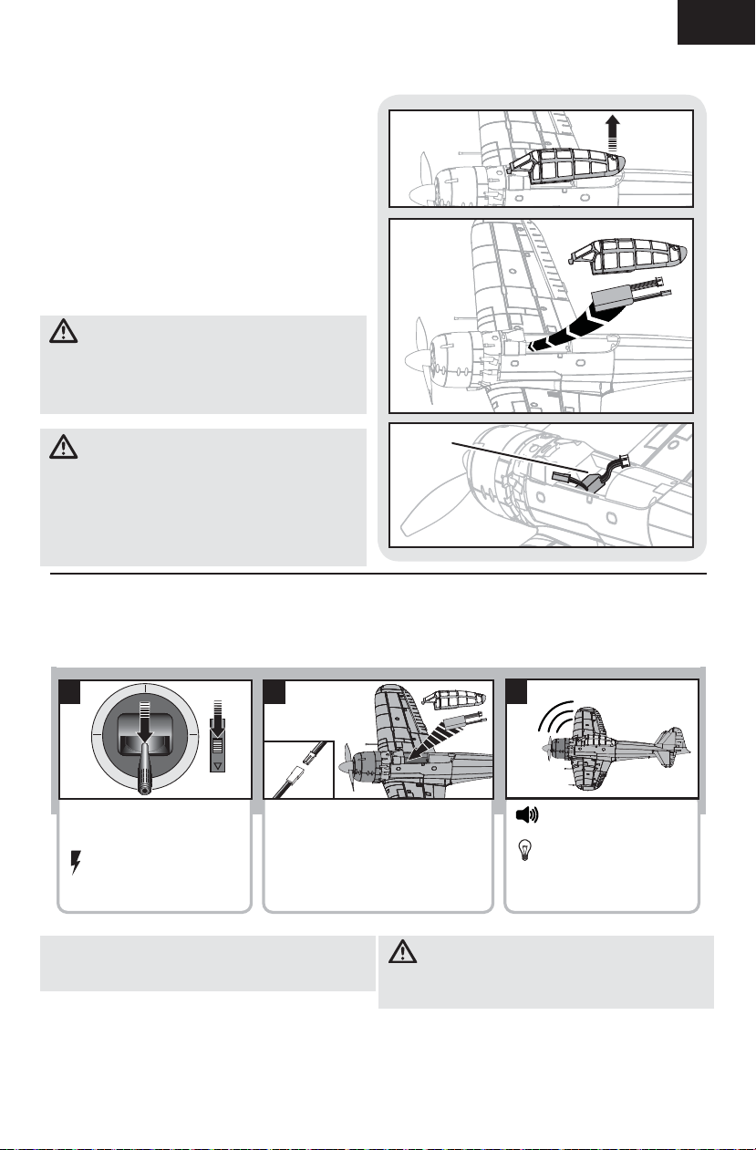
Arming the ESC
Arming the ESC also occurs after binding as previously described, but subsequent connection of a fl ight
battery requires the steps below.
1 2
Lower throttle and throttle
trim to lowest settings.
Power on the Transmitter,
then wait 5 seconds
Tip: If the ESC sounds a continuous double beep
after the fl ight battery is connected, recharge or
replace the battery.
If you accidentally connect the battery while
the throttle is fully opened, a musical tone will
sound after 5 seconds. Disconnect the battery
immediately.
Install fl ight battery and
connect it to the ESC.
CAUTION: Always keep hands away from the
propeller. When armed, the motor will turn the
propeller in response to any throttle movement.
3
Series of tones
Continuous LED
5
Page 6
EN
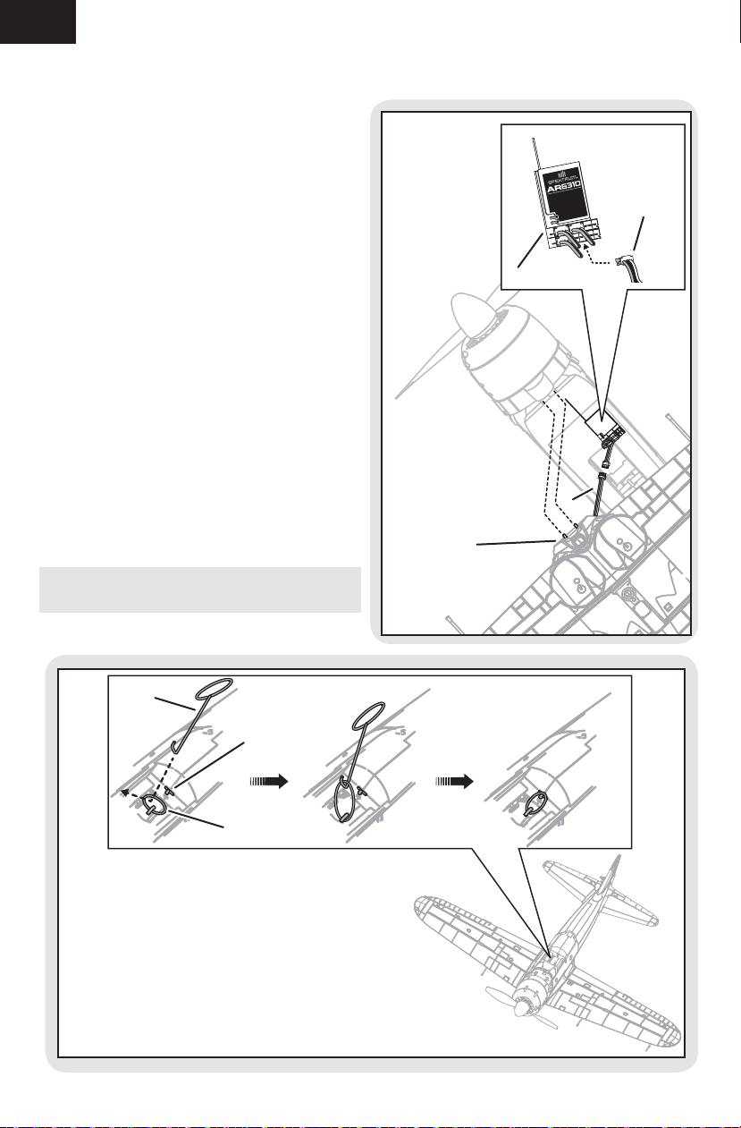
Installing the Wing
1. Turn over the model so the bottom of the
fuselage faces up.
2. Carefully install the micro connector of the
aileron servo (A) into the AIL port of the
receiver (B).
NOTICE: When disconnecting the servo connectors,
do not pull on the servo wires. Use a screwdriver
or pliers to break the friction fi t of the servo
connectors. Failure to do so could result in damage
to the servo wiring.
3. Insert the 2 wing pins (C) into the holes in the
front of the fuselage. Connect the back of the
wing to the fuselage.
NOTICE: DO NOT crush or otherwise damage wiring
when installing the wing on the fuselage.
4. Turn the aircraft right side up. Carefully use the
o-ring tool (D) to pull the o-ring (E) over the
hook in the fuselage (F).
NOTICE: Pulling too much on the O-ring can
damage the O-ring connector in the wing, requiring
replacement of the wing.
Tip: Before fl ying, always ensure the O-ring is in
good condition. Replace a worn or infl exible O-ring.
NANOLITE RECEIVER 2048
2.4GHz DSM® TECHNOLOGY
AUX 1
BIND
RUD
ELE
THR AILE
GEAR
A
B
A
C
5. Install the canopy on the fuselage.
D
F
E
6
Page 7

Control Centering
Before the fi rst fl ights, or in the event of an accident, make sure the fl ight control surfaces are
centered. Adjust the linkages mechanically if the
control surfaces are not centered.
1. Make sure the transmitter sub-trims are set
to zero and the servo arms are perpendicular
to the servo case.
2. When an adjustment of linkages is needed, pull
the tube from the clevis to the linkage.
3. Carefully spread the clevis and adjust the
length of the linkage by screwing the clevis in
or out. Reattach the clevis in the proper hole in
the control horn.
4. Move the tube to tighten the clevis onto the
control horn.
EN
Settings for Control Horns
The following illustration shows the factory settings
for linkages on the control horns. After fl ying, you
may choose to adjust the linkage positions for the
desired control response.
Elevator and Rudder
Control Direction Test
You should bind your aircraft and transmitter before doing these tests. Move the controls on the transmitter
to make sure the aircraft control surfaces move correctly and in the proper direction.
Make sure the tail linkages move freely and that paint or decals are not adhered to them.
7
Page 8

EN
Dual Rates and Expos
We recommend using a DSM radio capable of dual
rates. The settings below are recommended starting
settings. Adjust according to individual preferences
after the initial fl ight.
Adjusting Center of Gravity (CG)
The CG location is 43mm back from the leading
edge of the wing at the root.
Dual Rates High Rate Low Rate
Aileron 7mm up/down 5mm up/down
Elevator 9mm up/down 7mm up/down
Rudder 18mm left/right 15mm left/right
Expo High Rate Low Rate
Aileron 25% 15%
Elevator 25% 15%
Rudder 25% 15%
The battery cavity is oversized to allow for Center of
Gravity adjustment. Start by placing the battery fully
forward with the connectors facing the rear of the
aircraft. Adjust as needed by sliding the
battery back.
43mm
8
Page 9

Flying Tips and Repairs
EN
Flying
We recommend fl ying your E-fl ite® A6M5 Zero
outside in no greater than moderate winds or inside
in a large gymnasium. Always avoid fl ying near
houses, trees, wires and buildings. You should also
be careful to avoid fl ying in areas where there are
many people, such as busy parks, schoolyards or
soccer fi elds. Consult local laws and ordinances
before choosing a location to fl y your aircraft.
Wind
Hand launch
Get assistance to hand launch the aircraft so that
you can give full attention to transmitter control.
Hold the aircraft by the fuselage over the wings.
Give a fi rm underhand throw directly into the
wind slightly up (5–10 degrees above the horizon)
with full throttle. After the aircraft gains altitude,
decrease the throttle as you desire. If you have
no one to launch the aircraft with you, launch the
aircraft using the hand that isn’t operating the
elevator stick so that you have elevator control in
the critical fi rst few seconds of fl ight. Once you have
the Zero airborne, maintain a shallow rate of climb
and allow the aircraft to gain speed before making
the fi rst turn. Familiarize yourself with the fl ight
characteristics of the Zero and practice fl ying the
aircraft high enough so that you can recover control
if it does not respond as you desire.
Landing
Make sure to land into the wind. Fly the aircraft to
approximately 6 inches (15 cm) or less above the
runway, using a small amount of throttle for the
entire descent. Keep the throttle on until the aircraft
is ready to fl are. During fl are, keep the wings level
and the aircraft pointed into the wind. Gently lower
the throttle while pulling back on the elevator to
bring the aircraft down on its belly. Fully lower
the throttle just before the aircraft lands to avoid
propeller damage.
NOTICE: If a crash is
imminent, reduce the
throttle and trim fully.
Failure to do so could
result in extra damage to
the airframe, as well as
damage to the ESC and
motor.
NOTICE: Crash damage
is not covered under
warranty.
NOTICE: When you are
fi nished fl ying, never keep
the aircraft in the sun. Do not store the aircraft in
a hot, enclosed area such as a car. Doing so can
damage the foam.
Repairs
Repair this aircraft using foam-compatible CA
(cyanoacrylate adhesive) glue or clear tape. Only use
foam-compatible CA glue as other types of glue can
damage the foam. When parts are not repairable,
see the Replacement Parts List for ordering by
item number.
For a listing of all replacement and optional parts,
refer to the list at the back of this manual.
NOTICE: Use of foam-compatible CA accelerant on
your aircraft can damage paint. DO NOT handle the
aircraft until accelerant fully dries.
CAUTION
Always decrease
throttle before
propeller strike.
9
Page 10

EN
Post Flight Checklist
9
1. Disconnect fl ight battery from ESC
(Required for safety and battery life).
2. Power off transmitter.
3. Remove fl ight battery from aircraft.
4. Recharge fl ight battery.
9
5. Store fl ight battery apart from
aircraft and monitor the battery
charge.
6. Make note of fl ight conditions and
fl ight plan results, planning for
future fl ights.
Using the Display Stand
Tip: Glue is not required for the assembly of the display, but may be used if the display will not be
disassembled.
CAUTION: Always remove the battery before displaying the model.
NOTICE: Always remove the model from the display before adjusting the display. Failure to do so may result
in damage to the model or the display.
10
Page 11

Service of Power Components
Disassembly
CAUTION: Always disconnect the battery
before handling or adjusting the propeller or
motor. Failure to do so could result in
personal injury.
Propeller
1. Remove the spinner (A) from the propeller (B).
Before re-installing the spinner on the propeller,
scrape off as much excess glue as possible, making
sure not to damage the propeller blades or hub.
Never operate the aircraft with a damaged propeller.
2. Hold the propeller (E) stationary and use a
5mm wrench, pliers, or nut driver to remove
the 2.5mm locknut (C) and washer (D). The
propeller can then be removed from the motor
shaft (F).
Motor and Firewall
1. Carefully remove the cowling (G) from the
fuselage. Paint may hold the cowling on the
fuselage. Do not use excess force as the
cowling plasic is relatively thin and can tear.
EN
A
B
F
C
D
E
G
2. Remove 4 screws (H) from the motor mount (I)
and the fuselage.
3. Remove 2 screws (J) and the motor (K)
from the motor mount. The motor magnets
may attract screws to the motor.
4. Disconnect the motor wire connectors (L)
from the ESC/receiver connectors.
5. Assemble in reverse order.
• Reinstall the propeller by properly fitting it onto
the motor shaft, installing the flat washer, and
tightening the 2.5mm lock nut with a
5mm wrench, pliers, or nut driver.
• Align the colors of the motor wires and connect
them with the ESC wires.
• Correctly center the spinner on the propeller and
use only foam-compatible CA (cyanoacrylate
adhesive) to attach the spinner to the propeller.
L
G
I
J
H
K
11
Page 12

Troubleshooting Guide
Problem Possible Cause Solution
Aircraft will not respond
to throttle but responds
to other controls
Extra propeller noise or
extra vibration
Reduced fl ight time or
aircraft underpowered
LED on receiver fl ashes
and aircraft will not bind
to transmitter (during
binding)
Control surface does
not move
Controls reversed Transmitter settings reversed Adjust controls on transmitter appropriately
Motor power quickly
decreases and increases then motor
loses power
Motor/ESC is not armed
after landing
ESC did not arm because throttle stick and/
or throttle trim too high
Throttle channel is reversed Reverse throttle channel on transmitter
Motor disconnected from ESC Remove wing from fuselage and make sure
Damaged propeller, spinner or motor Replace damaged parts
Prop nut is too loose Tighten the prop nut
Prop is out of balance Remove and balance propeller, or replace
Flight battery charge is low Completely recharge fl ight battery
Propeller installed backwards Install propeller properly
Flight battery damaged Replace fl ight battery and follow fl ight battery
Flight battery is too cold Make sure battery is warm before use
Battery capacity too low for fl ight conditions Replace battery or use a larger capacity
Transmitter too near aircraft during binding
process
Bind switch or button not held long enough
during bind process
Control surface, control horn, linkage or
servo damage
Wire damaged or connections loose Do a check of wires and connections, con-
Flight battery charge is low Fully recharge fl ight battery
Control linkage does not move freely Make sure control linkage moves freely
Battery voltage is down to the point of
receiver/ESC Low Voltage Cutoff (LVC)
Over Current Protection (OCP) stops the
motor when the transmitter throttle is set
high and the propeller cannot turn
Lower throttle stick and throttle trim to lowest setting
motor is connected to the ESC
with a balanced propeller.
instructions
battery
Power off transmitter, move transmitter a
larger distance from aircraft, disconnect and
reconnect fl ight battery to aircraft and follow
binding instructions
Power off transmitter and repeat bind process. Hold transmitter bind button or switch
until receiver is bound
Replace or repair damaged parts and adjust
controls
nect or replace as needed
Recharge fl ight battery or replace battery that
is no longer performing
Fully lower throttle and throttle trim to arm
ESC
Page 13

Limited Warranty
What this Warranty Covers
Horizon Hobby, Inc. (“Horizon”) warrants to the original
purchaser that the product purchased (the “Product”) will
be free from defects in materials and workmanship at the
date of purchase.
What is Not Covered
This warranty is not transferable and does not cover
(i) cosmetic damage, (ii) damage due to acts of God,
accident, misuse, abuse, negligence, commercial
use, or due to improper use, installation, operation or
maintenance, (iii) modifi cation of or to any part of the
Product, (iv) attempted service by anyone other than
a Horizon Hobby authorized service center, (v) Product
not purchased from an authorized Horizon dealer, or
(vi) Product not compliant with applicable technical
regulations.
OTHER THAN THE EXPRESS WARRANTY ABOVE, HORIZON
MAKES NO OTHER WARRANTY OR REPRESENTATION, AND
HEREBY DISCLAIMS ANY AND ALL IMPLIED WARRANTIES,
INCLUDING, WITHOUT LIMITATION, THE IMPLIED
WARRANTIES OF NON-INFRINGEMENT, MERCHANTABILITY
AND FITNESS FOR A PARTICULAR PURPOSE. THE
PURCHASER ACKNOWLEDGES THAT THEY ALONE HAVE
DETERMINED THAT THE PRODUCT WILL SUITABLY MEET
THE REQUIREMENTS OF THE PURCHASER’S
INTENDED USE.
Purchaser’s Remedy
Horizon’s sole obligation and purchaser’s sole and
exclusive remedy shall be that Horizon will, at its option,
either (i) service, or (ii) replace, any Product determined
by Horizon to be defective. Horizon reserves the right to
inspect any and all Product(s) involved in a warranty claim.
Service or replacement decisions are at the sole discretion
of Horizon. Proof of purchase is required for all warranty
claims. SERVICE OR REPLACEMENT AS PROVIDED
UNDER THIS WARRANTY IS THE PURCHASER’S SOLE AND
EXCLUSIVE REMEDY.
Limitation of Liability
HORIZON SHALL NOT BE LIABLE FOR SPECIAL, INDIRECT,
INCIDENTAL OR CONSEQUENTIAL DAMAGES, LOSS OF
PROFITS OR PRODUCTION OR COMMERCIAL LOSS IN ANY
WAY, REGARDLESS OF WHETHER SUCH CLAIM IS BASED
IN CONTRACT, WARRANTY, TORT, NEGLIGENCE, STRICT
LIABILITY OR ANY OTHER THEORY OF LIABILITY, EVEN IF
HORIZON HAS BEEN ADVISED OF THE POSSIBILITY OF
SUCH DAMAGES. Further, in no event shall the liability
of Horizon exceed the individual price of the Product on
which liability is asserted. As Horizon has no control over
use, setup, fi nal assembly, modifi cation or misuse, no
liability shall be assumed nor accepted for any resulting
damage or injury. By the act of use, setup or assembly, the
user accepts all resulting liability. If you as the purchaser
or user are not prepared to accept the liability associated
with the use of the Product, purchaser is advised to return
the Product immediately in new and unused condition to
the place of purchase.
Law
These terms are governed by Illinois law (without regard to
confl ict of law principals). This warranty gives you specifi c
legal rights, and you may also have other rights which vary
from state to state. Horizon reserves the right to change
or modify this warranty at any time without notice.
WARRANTY SERVICES
Questions, Assistance, and Services
Your local hobby store and/or place of purchase cannot
provide warranty support or service. Once assembly, setup
or use of the Product has been started, you must contact
your local distributor or Horizon directly. This will enable
Horizon to better answer your questions and service
you in the event that you may need any assistance. For
questions or assistance, please visit our website at www.
horizonhobby.com, submit a Product Support Inquiry, or
call 877.504.0233 toll free to speak to a Product Support
representative.
Inspection or Services
If this Product needs to be inspected or serviced and is
compliant in the country you live and use the Product in,
please use the Horizon Online Service Request submission
process found on our website or call Horizon to obtain a
Return Merchandise Authorization (RMA) number. Pack
the Product securely using a shipping carton. Please note
that original boxes may be included, but are not designed
to withstand the rigors of shipping without additional
protection. Ship via a carrier that provides tracking and
insurance for lost or damaged parcels, as Horizon is
not responsible for merchandise until it arrives and is
accepted at our facility. An Online Service Request is
available at Horizon Hobby Service Center. If you do not
have internet access, please contact Horizon Product
Support to obtain a RMA number along with instructions
for submitting your product for service. When calling
Horizon, you will be asked to provide your complete name,
street address, email address and phone number where
you can be reached during business hours. When sending
product into Horizon, please include your RMA number,
a list of the included items, and a brief summary of the
problem. A copy of your original sales receipt must be
included for warranty consideration. Be sure your name,
address, and RMA number are clearly written on the
outside of the shipping carton.
NOTICE: Do not ship LiPo batteries to Horizon. If you
have any issue with a LiPo battery, please contact the
appropriate Horizon Product Support offi ce.
Warranty Requirements
For Warranty consideration, you must include your
original sales receipt verifying the proof-of-purchase
date. Provided warranty conditions have been met, your
Product will be serviced or replaced free of charge.
Service or replacement decisions are at the sole
discretion of Horizon.
Non-Warranty Service
Should your service not be covered by warranty, service
will be completed and payment will be required
without notifi cation or estimate of the expense unless
the expense exceeds 50% of the retail purchase
cost. By submitting the item for service you are agreeing
to payment of the service without notifi cation. Service
estimates are available upon request. You must include
this request with your item submitted for service. Nonwarranty service estimates will be billed a minimum of
½ hour of labor. In addition you will be billed for return
freight. Horizon accepts money orders and cashier’s
checks, as well as Visa, MasterCard, American Express,
and Discover cards. By submitting any item to Horizon
for service, you are agreeing to Horizon’s Terms and
Conditions found on our website Horizon Hobby
Service Center.
NOTICE: Horizon service is limited to Product
compliant in the country of use and ownership. If noncompliant product is received by Horizon for service, it
will be returned unserviced at the sole expense of
the purchaser.
13
EN
Page 14

EN
Warranty and Service Information
Country of
Purchase
United States
of America
United Kingdom Horizon Hobby Limited
Germany
France Horizon Hobby SAS
China Horizon Hobby – China
Horizon Hobby Address Phone Number/Email Address
Horizon Service Center
(Electronics and
engines)
Horizon Product
Support (All other
products)
Horizon Technischer
Service
4105 Fieldstone Rd
Champaign, Illinois
61822 USA
4105 Fieldstone Rd
Champaign, Illinois
61822 USA
Units 1-4 Ployters Rd
Staple Tye
Harlow, Essex
CM18 7NS
United Kingdom
Christian-Junge-Straße 1
25337 Elmshorn
Germany
14 Rue Gustave Eiffel
Zone d’Activité du Réveil Matin
91230 Montgeron
Room 506, No. 97 Changshou Rd.
Shanghai, China, 200060
877-504-0233
Online Repair Request visit:
www.horizonhobby.com/service
877-504-0233
productsupport@horizonhobby.com
+44 (0) 1279 641 097
sales@horizonhobby.co.uk
+49 (0) 4121 2655 100
service@horizonhobby.de
+33 (0) 1 60 47 44 70
infofrance@horizonhobby.com
+86 (021) 5180 9868
info@horizonhobby.com.cn
Compliance Information for the European Union
Declaration of Conformity
(in accordance with ISO/IEC 17050-1)
No. HH2012051301
Product(s): EFL A6M5 Zero 300
Item Number(s): EFL6175
Equipment class: 1
The object of declaration described above is in conformity with the requirements of the specifi cations listed
below, following the provisions of the European R&TTE directive 1999/5/EC:
EN 301 489-1 V1.7.1: 2006
EN 301 489-17 V1.3.2: 2008
Signed for and on behalf of:
Horizon Hobby, Inc.
Champaign, IL USA
May 13, 2012
Steven A. Hall
Vice President
International Operations and Risk Management
Horizon Hobby, Inc.
Instructions for disposal of WEEE by users in the European Union
This product must not be disposed of with other waste. Instead, it is the user’s responsibility
to dispose of their waste equipment by handing it over to a designated collections point
for the recycling of waste electrical and electronic equipment. The separate collection and
recycling of your waste equipment at the time of disposal will help to conserve natural
environment. For more information about where you can drop off your waste equipment for recycling, please
contact your local city offi ce, your household waste disposal service or where you purchased the product.
14
resources and ensure that it is recycled in a manner that protects human health and the
Page 15

– Replacement Parts –
– Ersatzteile –
– Pièces de rechange –
– Parti di ricambio –
Part # • Nummer
Numéro • Codice
EFL617501
EFL617502
EFL617503
EFL617504
EFL617505
EFL617506
EFL617507
EFL617508
EFL617509
EFLM7000
EFLA7300
EFLR7100
EFLR710001
EFLR710002
EFLA286
EFLA287
EFLA288
SPMAR6310
Description Beschreibung Description Descrizione
Fuselage: A6M5
Zero 300
Wing: A6M5 Zero
300
Canopy Hatch:
A6M5 Zero 300
Cowling: A6M5 Zero
300
7x6e Propellers (2)
A6M5 Zero 300
Spinner: A6M5 Zero
300
Pushrods with
Clevis: A6M5 Zero
300
Display Bomb with
Guns: A6M5 Zero
300
Control Horns:
A6M5 Zero 300
Motor: 300 Brushless Outrunner,
1400Kv
10-Amp Brushless
ESC
3.5 g Digital SubMicro Servo
Gear Set: EFLR7100 E-fl ite Getriebe Set:
Servo Arm Set:
EFLR7100
Display Stand: 300Size Warbirds
O-Ring Tool: 300size Warbirds
O-Rings (3): 300size Warbirds
AR6310 DSMX
Nanolite 6-Channel
Receiver
E-fl ite Rumpf : A6M5
Zero 300
E-fl ite Tragfl äche:
A6M5 Zero 300
E-fl ite Kabinenhaube
: A6M5 Zero 300
E-fl ite Motorhaube :
A6M5 Zero 300
E-fl ite Propeller (2):
A6M5 Zero 300
E-fl ite Spinner: A6M5
Zero 300
E-fl ite Gestänge mit
Gabelköpfen : A6M5
Zero 300
E-fl ite Display
Bomben und MG´s :
A6M5 Zero 300
E-fl ite Ruderhörner :
A6M5 Zero 300
E-fl ite Motor:
300 Brushless
Aussenläufer 1400Kv
E-fl ite 10-Amp
Brushless ESC
E-fl ite 3.5g Digital
Servo
EFLR7100
E-fl ite Servo Arm Set:
EFLR7100
E-Flite Display
Ständer 300-Size
Warbirds
E-fl ite O-Ring
Werkzeug : 300er
Warbirds
E-fl ite O-Ringe (3):
300er Warbirds
Spektrum 6 Kanal
Nanolite Empfänger
DSM X
A6M5 Zero 300
-Fuselage
A6M5 Zero 300 -Aile Ala: A6M5 Zero 300
A6M5 Zero 300
-Verrière
A6M5 Zero 300 -Capot Capottina motore:
A6M5 Zero 300
-Hélice 7x6e (2)
A6M5 Zero 300 -Cône Ogiva: A6M5 Zero 300
A6M5 Zero 300 -Tringleries avec chapes
A6M5 Zero 300
-Bombe factice avec
canons
A6M5 Zero 300
-Guignols
Moteur Brushless
300 à cage tournante,
1400Kv
Contrôleur Brushless
10A
Sub micro servo
digital 3.5g
Jeu de pignons :
EFLR7100
Bras de servos
EFLR7100
Socle pour warbird
classe 300
Outil à joint torique
pour warbird classe
300
Joints toriques (3)
pour warbird classe
300
Récepteur AR6310
DSMX Nanolite 6 voies
Fusoliera: A6M5 Zero
300
Capottina: A6M5 Zero
300
A6M5 Zero 300
Eliche 7x6e (2) A6M5
Zero 300
Comandi con forcelle:
A6M5 Zero 300
Supporto bombe con
armi: A6M5 Zero 300
Squadrette: A6M5 Zero
300
Motore: 300 Brushless
cassa rotante,1400Kv
Regolatore (ESC) 10Amp Brushless
Servo digitale SubMicro 3.5 g
Set ingranaggi per
EFLR7100
Set squadrette per
EFLR7100
Piedestallo esposizione: per caccia classe
300
Attrezzo O-Ring: per
caccia classe 300
O-Rings (3): per caccia
classe 300
Ricevitore 6 canali
AR6310 DSMX Nanolite
54
Page 16

– Optional Parts and Accessories –
– Optionale Bauteile und Zubehörteile –
– Pièces optionnelles et accessoires –
– Parti opzionali e accessori –
Part # • Nummer
Numéro • Codice
EFLA230
EFLA250
EFLB4302S
EFLB4502S30
EFLC3005
Description Beschreibung Description Descrizione
Charger Lead with
JST Female
Park Flyer Tool Assortment, 5 pc
430mAh 2S 7.4V 25C
Li-Po
450mAh 2S 7.4V 30C
Li-Po
DC 1-3S Li-Po
Charger
DX4e DSMX
4-channel Transmitter
DX5e DSMX
5-channel Transmitter
DX6i DSMX 6-Channel
Transmitter
DX7s DSMX
7-Channel Transmitter
DX8 DSMX Transmitter Spektrum DX8 nur
E-fl ite Ladekabel m/
JST Buchse
Park Flyer Werkzeugsortiment, 5 teilig
430mAh 2S 7.4V
25C Li-Po Akku
450mAh 2S 7.4V
30C Li-Po Akku
DC 1-3S Li-Po
Ladegerät
Spektrum DX4Ee
DSMX 5 Kanalsender
ohne Empfänger
Spektrum DX5Ee
DSMX 5 Kanalsender
ohne Empfänger
DX6i DSMX 6-Kanal
Sender
Spektrum DX7s
7 Kanal Sender
Sender
Câble de charge avec
prise JST femelle
Assortiment d’outils
Park Flyer, 5pc
Batterie Li-Po 7.4V
2S 430mA 25C
Batterie Li-Po 7.4V
2S 450mA 30C
Chargeur Li-Po
DC 1-3S
Emetteur DX4e DSMX
4 voies
Emetteur DX5e DSMX
5 voies
Emetteur DX6i DSMX
6 voies
Emetteur DX7s DSMX
7 voies
Emetteur DX8 DSMX
8 voies
Cavo di carica con
femmina JST
Park Flyer assortimento attrezzi, 5 pc
Batteria Li-Po430mAh 2S 7.4V 25C
Batteria Li-Po450mAh 2S 7.4V 30C
Caricabatterie Li-Po
CC da 1-3S
DX4e DSMX
Trasmettitore 4 canali
DX5e DSMX
Trasmettitore 5 canali
DX6i DSMX Trasmettitore 6 canali
DX7s DSMX
Trasmettitore 7 canali
DX8 DSMX Solo
trasmettitore
– Parts Contact Information –
– Intaktinformationen für Ersatzteile –
– Coordonnées pour obtenir des pièces détachées –
– Contatti per le parti di ricambio –
Country of Purchase Horizon Hobby Address Phone Number/Email Address
United States Sales
United Kingdom Horizon Hobby Limited
Germany Horizon Hobby GmbH
France Horizon Hobby SAS
China Horizon Hobby – China
4105 Fieldstone Rd
Champaign, Illinois, 61822 USA
Units 1-4 Ployters Rd
Staple Tye
Harlow, Essex
CM18 7NS, United Kingdom
Christian-Junge-Straße 1
25337 Elmshorn, Germany
14 Rue Gustave Eiffel
Zone d’Activité du Réveil Matin
91230 Montgeron
Room 506, No. 97 Changshou Rd.
Shanghai, China, 200060
800-338-4639
sales@horizonhobby.com
+44 (0) 1279 641 097
sales@horizonhobby.co.uk
+49 (0) 4121 2655 100
service@horizonhobby.de
+33 (0) 1 60 47 44 70
infofrance@horizonhobby.com
+86 (021) 5180 9868
info@horizonhobby.com.cn
55
Page 17

© 2012 Horizon Hobby, Inc.
E-fl ite, JR, Celectra, DSM, DSM2, and Bind-N-Fly are trademarks or registered
trademarks of Horizon Hobby, Inc.
DSMX is a trademark of Horizon Hobby, Inc., registered in the U.S.
The Spektrum trademark is used with permission of Bachmann Industries, Inc.
Futaba is a registered trademark of Futaba Denshi Kogyo Kabushiki Kaisha
Corporation of Japan.
Patents pending
www.e-fl iterc.com
EFL6175
Created 2/13 31030.1
 Loading...