

Page 1

Wv410 window
Installation Instructions
Part NO. Y007
February 2014
Page 2

WV410 WINDOW - INSTALLATION INSTRUCTIONS
TABLE OF CONTENTS
SECTION PAGE
I. Product Description and Limitations…...………….………………....…...3
II. General Statements and Definitions..……………….………..…………....3
III. Standard Parts Identification……………….…………….…….….……….…4
IV. Size Formulas
A. Window and Glass Size Formulas……..………………………………....5
B. Egress Formulas…………………………..……………………..…...…..…..6
V. Captured WV410 Vent Glazing….……………………………………..…….7-8
VI. SSG WV410 Vent Glazing………..………………………………………….9-10
VII. Vent Gasket Preparation…………………………………………………...11
VIII.
Window Installation
A. Single Window Installation……………………………………….…………12
B. Dual Window Installation…………………………………………………..13-15
C. Ribbon Window Installation……………………………………………….16-19
IX. Casement Lift Block Installation…………………………………….………20
X.
Note: Please reference EFCO's "Understanding Condensation" brochure which can be obtained through your EFCO representative.
Condensation will form on any surface when unfavorabl e cond itions (interior temperature and relative humidity and exterior
temperature) are present. When the formation of excessive condensation is a concern, it is highly recomm ended that a design
professional is utilized to perform an analysis of the shop drawings to recommend the best possible installation methods. Please
contact your EFCO representative for information on EFCO's Thermal Analysis Services.
Many current installation practices lead to an increase in the possibility of the formation of condensati on. Though not all
inclusive, the list of examples below illustrates conditions under which condensation is likely to occur:
Vent Removal and Adjustment..……………..……..…….…………..…..….21
Minimizing Condensation
1. Bridging system thermal break with non-thermally broken metal flashing or lintels that are exposed to the exterior
2. System exposure to cold air cavities
3. Interior relative humidity levels not maintained at recommended levels, see EFCO’s “Understanding
Condensation” brochure
4. Inadequate separation between system and surrounding condition at perimeter
5. Product combinations during the shop drawing stage that result in bridging thermal brea ks
of one or all products involved
EFCO CORPORATION 2/2014 PART NO. Y007 Page 2 of 21
Page 3

WV410 WINDOW - INSTALLATION INSTRUCTIONS
Section I – Product Description and Limitations
The WV410 storefront window system is designed and engineered to be field glazed and installed
with a limited amount of labor and tools. Although the WV410 window is designed to
complement the S401, S402, S403, and S433 center set systems, it may be glazed into any
system with a smooth surface opening that has a minimum depth of 3 7/16”.
The WV410 allows the plane of glass to be equal to that of the S401, S402, S403, and S433
center set systems. The correct location or inset of the WV410 is easily found by measuring out
from the interior surface to the storefront 1/32”. This will allow a 1/32” offset from the storefront
face to the window frame. If the WV410 intermediate mullion is used, the interior face of the
mullion will align flush with the storefront horizontal.
Section II – General Statements and Definitions
The user is encouraged to read and understand all of the instructions prior to proceeding with
installation. These instructions define several configurations and methods of installation that may
or may not apply to your project.
The instructions covered in this manual are pertinent to the S401, S402, S403, and S433 systems.
Consult approved shop drawings for special applications not covered herein.
The following terminology will be utilized throughout these instructions and has been included to
better orient the reader to the areas discussed.
Storefront Opening: Storefront or other mounting surface for the window are typically called
D.L.O. (Day Light Opening).
WV410 Frame: The interior mounting and fixed portion of the operable window.
Vent: The operable and glazed portion of the window.
Intermediate mullion: The adaptor system designed to allow the windows to be stacked side by
side in a dual or ribbon application.
The steps and details on the following pages have been developed to aid in the assembly and
installation of the WV410 storefront window system.
EFCO CORPORATION 2/2014 PART NO. Y007 Page 3 of 21
Page 4
WV410 WINDOW - INSTALLATION INSTRUCTIONS
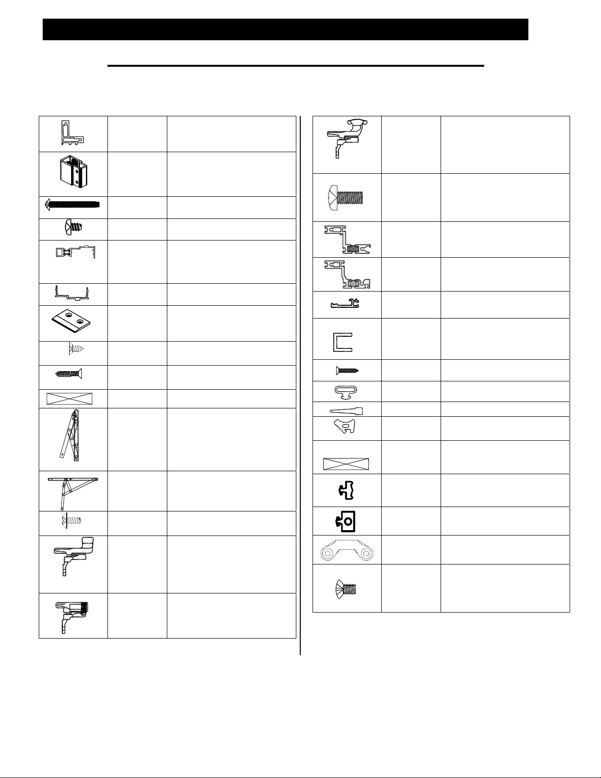
Section III – Standard Parts Identification
Detail Part No. Description Detail Part No. Description
WV410 Frame
9833
K320
MRF7
SPC7
1F10
9837
HB64
Use with 23X3 or 23X4 vent
WV410 Mullion Shear
Block Package
2) packages required per mullion
complete with fasteners
Shear block to storefront
screw- included in K320
Mullion to shear block screwincluded in K320
Female Vertical Mullion
Half
Thermal Strut Connected
Used with K320 and 9867
Male Vertical Mullion Half
Used with K320 and 1F10
Casement Vent Lift Block
Use SFZ5 attachment screws
Lift Block Attachment
Screw
WV410 Frame to
Storefront
Perimeter Shim Block
4-Bar Hinge
used for casement and projected
hinges
90° 4-Bar Hinge
Casement vents only- Minimum
casement width = 19 5/8”
SFZ5
SFP1
HN91
LA09
LA15
LA21
LA23
LA01
H989
H990
H991
H992
MFM3
MFM4
23X4
23X3
9834
EY45
SFP1
W142
W113
WEB5
HN91
W174
STT5
H927
H928
H935
4-Bar Hinge Attachment
Screw
Cam Handle (RH) (CLR)
Cam Handle (LH) (CLR)
Cam Handle (LH) (BRZ)
Cam Handle (RH) (BRZ)
(6) per hinge
H936
A.C. Lock (CLR)
H987
H988
A.C. Lock (BRZ)
WEQ4
HK15
HP15
MON9
MOO0
* Drawings on this page are not to scale.
Pole Ring Cam Handle (RH) (CLR)
Pole Ring Cam Handle (LH) (CLR)
Pole Ring Cam Handle (RH) (BRZ)
Pole Ring Cam Handle (LH) (BRZ)
Cam Handle Attachment
Screw (CLR)
Cam Handle Attachment
Screw (BRZ)
Standard Bead Glazed
Vent
Structural Glazed Vent
Removable Glass Stop
Used with 23X4 Vent
¼” Glazing Adaptor
Channel
use SFP1 attachment screws
Attachment screw
Use at ¼” glazing adaptor
Vent Bulb Gasket
Perimeter Wiper Gasket
Removable Glass Stop
Glazing Wedge
Glass Setting Block
(4) required per casement vent
(8) required per projected vent
1/8” Pre-shim Gasket
For bead glazed vents
¼” SSG Pre-shim Gasket
For SSG glazed vents
Strike (CLR)
Strike (BRZ)
Strike Attachment Screw
(CLR)
Strike Attachment Screw
(BRZ)
EFCO CORPORATION 2/2014 PART NO. Y007 Page 4 of 21
Page 5
WV410 WINDOW - INSTALLATION INSTRUCTIONS
Section IV – Size Formulas
A. Window and Glass Size Formulas
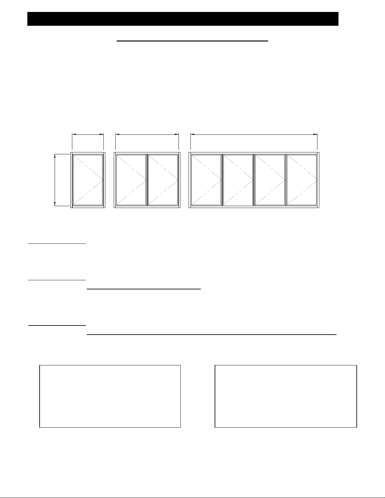
There are three (3) different configurations of the WV410 window system. Each of the
configurations will determine the horizontal dimensions of the glass and individual units.
Note: The storefront D.L.O. horizontal and vertical dimensions must be known to calculate the
sizes. Glass and window size formulas for the WV410 units are provided below for each
configuration. Refer to the information given that corresponds with the appropriate configuration.
STOREFRONT
D.L.O. WIDTH
STOREFRONT
D.L.O. WIDTH
A B
STOREFRONT
D.L.O. HEIGHT
STOREFRONT
D.L.O. WIDTH
C
DUAL VENTSSINGLE VENT
RIBBON RUN VENTS
Configuration “A”
Window Width = Storefront D.L.O. Width – 3/8”
Window Height = Storefront D.L.O. Height – 3/8”
Configuration “B”
Window Width = (Storefront D.L.O. Width – 1 3/8”)
2
Window Height = Storefront D.L.O. Height – 3/8”
Configuration “C”
Window Width = ( Storefront D.L.O. Width – 3/8”) – (Number of Intermediate Mullions x 1”)
Number of Windows
Window Height = Storefront D.L.O. – 3/8”
Standard Glazing
Glass Size Formula
Configurations “A”, “B”, & “C”
Glass width = Window width – 1 1/2”
Glass height = Window height – 1 1/2”
Structural Glazed
Glass Size Formula
Configuration “A”, “B”, & “C”
Glass width = Window Width – 1 1/2”
Glass Height = Window Height – 1 1/2”
* Drawings on this page are not to scale.
EFCO CORPORATION 2/2014 PART NO. Y007 Page 5 of 21
Page 6
WV410 WINDOW - INSTALLATION INSTRUCTIONS
Section IV- Size Formulas
B. Egress Formulas
Egress openings must be figured based on the clear opening after the vent is opened to the 90
degree position. See the figures and equations below for window sizes at the egress opening.
Use standard window sizing requirements as shown on Page 5 once the egress has been used to
determine the storefront D.L.O. size.
Egress Windows must use LA01 Arms Only!
STOREFRONT D.L.O.
EGRESS OPENING =
STOREFRONT D.L.O. - 8 3/8"
EGRESS OPENING =
STOREFRONT D.L.O. - 3 3/8"
STOREFONT
D.L.O.
* Drawings on this page are not to scale.
Storefront D.L.O. width – 8 3/8” = 90 degree clear opening width
Storefront D.L.O. height – 3 3/8” = Egress clear opening height
EFCO CORPORATION 2/2014 PART NO. Y007 Page 6 of 21
Page 7
WV410 WINDOW - INSTALLATION INSTRUCTIONS
Section V – Captured WV410 Vent Glazing
Step 1
Unlock the cam locks and open the vent to expose the hardware. Remove the vent from the
WV410 frame by removing the screws from the hinges. Be sure to mark the vent to correspond
with the appropriate frame. This will insure that the vent is reinstalled correctly.
Step 2
Lay the vent face up on a flat, smooth working surface. Remove the glass stops from the vent.
Step 3
Make sure that the glazing surfaces of the vent are free from oil and metal shavings. Clean the
glazing surfaces as needed with alcohol. (Do not use glass cleaners).
Step 4
Insert a continuous row of pre-shimmed gasket W174 around the vent perimeter glazing leg.
Insert the gasket beginning at each end of the frame and work toward the middle then work out
any waves toward the ends forming tight joints. Do not stretch the gasket.
Step 5
Run a continuous bead of structural silicone sealant behind the tape as shown in Figure 1.
Step 6
Keeping the glass level and centered within the vent material, lower the glass down into place.
Structural
Silicone
Pre-Shimmed
Gasket
Figure 2
Figure 1
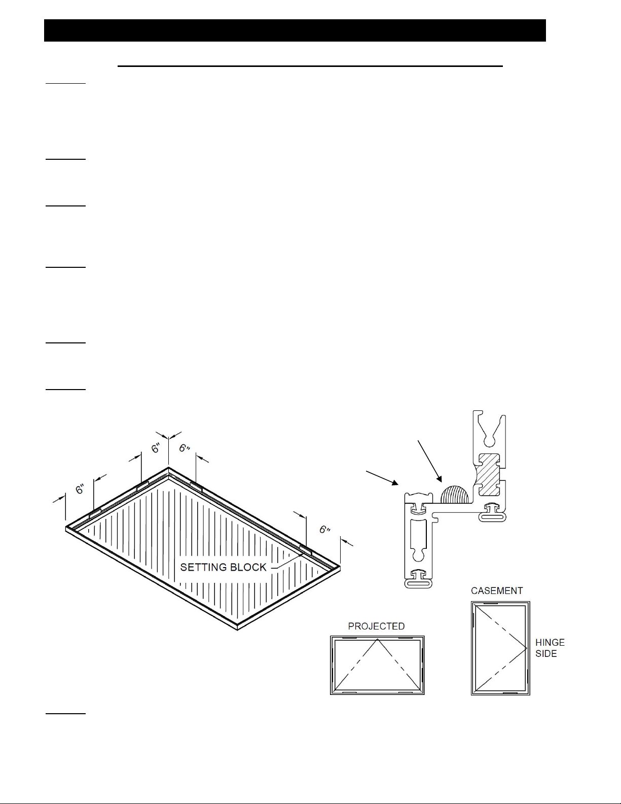
Step 7
Insert two (2) HN91 - 3/16” x 1” x 4” setting blocks on each side of the glass 6” from the corners,
as required, based on the configurations shown in Figure 2 above. Adjust the blocks as required
to keep the vent square.
EFCO CORPORATION 2/2014 PART NO. Y007 Page 7 of 21
Page 8

WV410 WINDOW - INSTALLATION INSTRUCTIONS
Section V – Captured WV410 Vent Glazing
Step 8
Reinstall the glass stops. The glass stops are designed to be inserted into the vent material and
rotated up and out toward the edges to lock into place. Insert a 3” long temporary piece of the
glazing wedge WEB5 at the midpoint of each stop until all four (4) are in place. See Figure 3.
WEB5
Drive-In
Gasket
Note: Horizontal
Gaskets Run Through
Figure 3
Pivot Point
Step 9
Cut the horizontal and ve rt ical lengths of the WEB5 drive-in gasket to the exterior daylight
opening of the vent plus 2% to allow for shrinkage. Insert the glazing wedge, beginning at each
end of the stops and the middle of the gasket. Continue to divide each loop in half, working out
the “waves” toward the ends of the glass stops. Do not stretch the gasket. See Figure 4.
Figure 4
Figure 5
WEB5 GLAZING
GASKET
Pre-Shimmed
Gasket
Step 10
After all of the gaskets are in place, flip the vent over and check for squeeze out that may have
appeared. Clean off any excess with a razor blade and paper towels.
* Drawings on this page are not to scale.
EFCO CORPORATION 2/2014 PART NO. Y007 Page 8 of 21
Page 9

WV410 WINDOW - INSTALLATION INSTRUCTIONS
Section VI – SSG WV410 Vent Glazing
Step 1
Unlock the cam locks and open the vent to expose the hardware. Remove the vent from the
WV410 frame by removing the screws from the hinges. Be sure to mark the vent to correspond
with the appropriate frame. This is to insure that the vent is reinstalled correctly.
Step 2
Lay the vent face up on a flat, smooth working surface.
Step 3
Make sure that the glazing surfaces of the vent are free from oil and metal shavings. Clean the
glazing surfaces as needed with alcohol. (Do not use glass cleaners).
Step 4
Insert a continuous row of pre-shimmed gasket WEQ4 around the vent perimeter glazing leg.
Insert the gasket beginning at each end of the frame and work toward the middle then work out
any waves toward the ends forming tight joints. Do not stretch the gasket.
Step 5
Run a continuous bead of structural silicone sealant behind the tape as shown in Figure 6.
Step 6
Keeping the glass level and centered within the vent material lower, the glass down into place.
Figure 7
* Drawings on this page are not to scale.
Pre-Shimmed
Gasket
Structural
Silicone
Figure 6
EFCO CORPORATION 2/2014 PART NO. Y007 Page 9 of 21
Page 10

WV410 WINDOW - INSTALLATION INSTRUCTIONS
Section VI – SSG WV410 Vent Glazing
Step 7
Insert two (2) HN91 - 3/16” x 1” x 4” setting blocks on each side of the glass 6” from the corners,
as required, based on the configurations shown in Figure 7. Adjust the blocks as required to keep
the vent square.
Step 8
Insert backer rod material between the glass and the vent material around the entire perimeter
except at setting block locations. The backer rod needs to be recessed far enough to leave the
end of the outer glass lite exposed. See figure 8.
Step 9
Mask off the outside edges of the glass and vent to minimize cleanup and provide a professional
appearance. Fill the void between the glass and the vent with structural sealant. Tool in sealant
and remove the masking tape before a skin begins to form. See Figure 8.
An overnight setup is required to allow the silicone to partially cure before movement of the unit.
Figure 8
* Drawings on this page are not to scale.
EFCO CORPORATION 2/2014 PART NO. Y007 Page 10 of 21
Page 11

WV410 WINDOW - INSTALLATION INSTRUCTIONS
Section VII – Vent Gasket Preparation
The exterior weatherstrip flap is to be trimmed at the sill to jamb corners. Trim the weatherstrip
3” from the sash corner both horizontally and vertically. This gasket preparation applies to both
Captured & SSG versions of the WV410 vents. See Figure 9.
Figure 9
EFCO CORPORATION 2/2014 PART NO. Y007 Page 11 of 21
Page 12

WV410 WINDOW - INSTALLATION INSTRUCTIONS
Section VIII – Window Installation
A. Single Window Installation
Step 1
Locate the 1/32” inset for the WV410 frame at the horizontal mullions of the storefront D.L.O.
Step 2
The WV410 frame is mounted into the storefront opening by first drilling and countersinking
attachment holes. Drill .201” diameter (No. 7 drill) mounting holes at the WV410 frame and
countersinking for No. 10 FH-SMS SFP1 screws, 4” from the ends and 16” on center maximum.
NOTE: Be sure not to re-drill or countersink through the hinge mounting holes. See Figure 12
below.
Fig u re #12
4"
E
4"16"16"16"
4"
16"
16"
16"
4"
Detail E
F
F
Note: Do not re-drill or
countersink through the hinge
.625"
mounting holes.
Section F-F
* Drawings on this page are not to scale.
Step 3
Place the WV410 frame into position keeping the 1/32” offset from the interior face of the
storefront to the interior face of the WV410 frame. Place HN91 shims at the mounting screw
location and clamp the WV410 frame into place. Using the WV410 frame as a guide, drill .159”
diameter (No. 21 drill) holes into the storefront frame. Secure the vent with SFP1 screws.
Step 4
Prior to installing the window, refer to Step 8 on page 14 for the required sealing locations. If
casement vents are used, see Section VIII for lift block installation. If projected windows are
used, continue to Step 5 for vent installation.
Step 5
Reinstall the vent into the WV410 frame. Be sure to mount the hinge to the same location as
preinstalled by EFCO. See Section IX on page 20.
EFCO CORPORATION 2/2014 PART NO. Y007 Page 12 of 21
Page 13

WV410 WINDOW - INSTALLATION INSTRUCTIONS
Section VIII – Window Installation
B. Dual Window Installation
The procedure for installing the vertical mullion in a dual window application differs fr om the
ribbon run application. In a dual window application, the WV410 frame side clearances are ample
enough to install the windows after the vertical mullion. In a dual window application the mullion
is always installed first.
Step 1
Establish the mullion center lines in the opening per the approved shop drawings. Refer to the
elevation in Figure 13 to locate the mullion center.
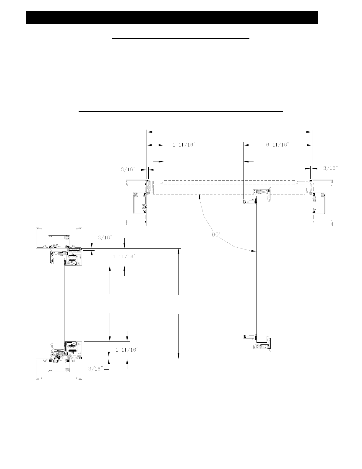
Step 2
Cut the vertical mullion halves 1F10/9837 to the daylight opening height and prep the ends as
detailed in Figure 14 below.
* Drawings on this page are not to scale.
EFCO CORPORATION 2/2014 PART NO. Y007 Page 13 of 21
Page 14

WV410 WINDOW - INSTALLATION INSTRUCTIONS
Section VIII – Window Installation
B. Dual Window Installation
Step 3
At the predetermined mullion locations, drill and tap the storefront horizontals for two (2) MRF7
10-24 PH-SMS fasteners. See Figure 15 below.
#SPC6
#9837
#
K320
Figure #15
#MRF7
#1F10
Detail G
Interior of
Storefront
Shear block and all screws are
included in the K320 package.
(2) required per mullion.
C/L of
Mullion
DETAIL G
DETAIL G
7/8 in [.874]
7/32 in [.224]
15/32 in [.467]
* Drawings on this page are not to scale.
Interior of
Storefront
Step 4
First apply sealant to the attachment hole in the storefront horizontals to insure against water
penetration, then install the K320 shear blocks using (2) MRF7 screws.
Step 5
Apply sealant to both ends of the female 1F10 and the male 9837 halves of the vertical mullion.
Step 6
Attach female portion 1F10 of the mullion to the shear block with (1) SFP6 screws at each end of
the mullion half. See Figure 15 above.
EFCO CORPORATION 2/2014 PART NO. Y007 Page 14 of 21
Page 15

WV410 WINDOW - INSTALLATION INSTRUCTIONS
Section VIII – Window Installation
B. Dual Window Installation
Step 7
Install the male portion 9837 of the mullion over the shear blocks and snap into the female
portion of the mullion. Attach the male mullion half to the shear blocks with (1) SPC6 fastener at
each end. See Figure 15 on page 13.
Step 8
NOTE: Do not complete this step unless you are prepared to install the window into the prepared
openings. Seal around the top and bottom edge of the mullion. Additionally, apply a continuous
bead of sealant along the mullion at the interlock location at both sides of the mullion as shown in
Figures 16 and 17.
Mullion interlock
TYPICAL SEAL AT THE
HEAD, JAMB, & SILL
INTERIOR
Sealant
JAMB
MULLION
Figure 17
Figure 16
* Drawings on this page are not to scale.
Step 9
The WV410 frame installation may now be completed. Both WV410 frames are installed by
inserting the windows into the openings at the jamb sides and sliding them toward the mullion.
Position the WV410 frames tight against the interlock of the mullion and shim into place with one
(1) HN91 shim at the top, bottom, and extreme jambs at each fastener location. Refer to Steps 1
through 3 on pages 11 and 12 for the recommended fastener locations. No shims are required at
the mullion anchor locations.
Step 10
After the WV410 frames have been installed, seal the exterior perimeter joint between the WV410
frame and the storefront frame and the mullion. At the interior of the storefront jamb, seal the
joint between the WV410 frame and the storefront frame. No additional sealant is required at the
interior surface of the mullions. See Figure 17.
EFCO CORPORATION 2/2014 PART NO. Y007 Page 15 of 21
Page 16

WV410 WINDOW - INSTALLATION INSTRUCTIONS
Section VIII – Window Installation
C. Ribbon Window Installation
The legs of the window engage the tracks of the vertical mullions, allowing a positive location
situation for the windows. The ribbon run installation is the same as the dual window installation
where the first mullion is installed prior to the WV410 frames. After the first mullion is installed,
the remaining window and mullions will be sequentially stacked. See Figure 18.
The mullion center lines must be laid out before the first window can be installed. Take into
account the 3/16” shim at the extreme jambs and the leg engagement at the vertical mullion.
The vertical mullion is designed to be set flush with the interior side of the storefront frame. This
is necessary to position the vent glass in the same plane as the storefront glass.
* Drawings on this page are not to scale.
EFCO CORPORATION 2/2014 PART NO. Y007 Page 16 of 21
Page 17

WV410 WINDOW - INSTALLATION INSTRUCTIONS
Section VIII – Window Installation
C. Ribbon Window Installation
Step 1
Follow the procedures detailed in Steps 1 through 10 of pages 12 through 14 for the first mullion
and WV410 frame.
Step 2
After the first and second WV410 frames have been installed, the method of installation will differ
from the previous steps. Beginning at the exposed jamb of the second WV410 frame, seal around
the top and bottom of the WV410 frame where it meets the storefront horizontals. Run a bead of
sealant along the interlock of the vertical frame. See Figure 20.
#1F10 Female
Mullion Ha lf
DETA IL I
DETA IL I
1st Vent
Frame
Figure #2 1
I
Exterior
Surface
2n d Vent
Frame
Figure #20
K320
#9837 Male
H
Apply sealant to
the Vent Frame
Interlock
Seal joints at the top
and bottom of the
vent frame
Mullion Half
DETAIL H
DETAIL H
* Drawings on this page are not to scale.
EFCO CORPORATION 2/2014 PART NO. Y007 Page 17 of 21
Page 18

WV410 WINDOW - INSTALLATION INSTRUCTIONS
Section VIII – Window Installation
C. Ribbon Window Installation
Step 3
Apply sealant to both ends of the female half of the mullion and apply to the interlock of the
WV410 frame. See Figure 20 on page 15.
Step 4
Install one (1) K320 shear block and two (2) MRF7 screws at the top and bottom horizontal.
NOTE: The screw holes must be predrilled and tapped for screw insertion. Due to the available
space within the mullion, a long handled screwdriver is recommended. See Figure 22.
J
Figure 22
DETAIL J
* Drawings on this page are not to scale.
DETAIL J
Step 5
Insert one (1) SPC6 into the shear block at the top and bottom of the mullion half to secure. See
Figure 15 on Page 13.
Step 6
Apply sealant to both ends of the male half 9837 of the mullion, snap into the female portion, and
fasten with (1) SPC6 at each end of the shear block. See Figure 15 on Page 13.
Step 7
Seal around the top and bottom of the mullion and the window interlock to receive the next
window. See Figure 16 on Page 14.
EFCO CORPORATION 2/2014 PART NO. Y007 Page 18 of 21
Page 19

WV410 WINDOW - INSTALLATION INSTRUCTIONS
Section VIII – Window Installation
C. Ribbon Window Installation
Step 8
Install the next WV410 frame by aligning the interlock of the window with the mullion interlock.
Step 9
Shim the WV410 frame into the correct location and anchor to the opening at the top, bottom,
and mullion side at the recommended locations covered in Steps 2 through 3 on Pages 16 and 17.
Step 11
After the WV410 frames and intermediate mullions have been installed, the interior and exterior
perimeter seals are to be applied. Seal the interior joint between the vertical frame and the
storefront opening at the top, bottom, and end jambs of the ribbon run. The vertical mullion
required no additional sealant at the interior surface. The exterior joint between the WV410
frame, storefront opening, and the intermediate vertical requires a continuous seal at all four (4)
sides of the WV410 frames. See Figure 21 on Page 16 and Figure 23 below.
Typical Seal at the Head, Jamb,
Mullion, and Sill
Interior
Figure 23
Jamb
Mullion
* Drawings on this page are not to scale.
Step12
If your application includes projected vents only, the operable vent may now be installed. See
section IX on page 20. Casement vents must first have the lift blocks installed. See Section VIII
on Page 19 for installation. Reinstall the operable vent to the WV410 frame. Be sure to mount
the vent and hinges in the same locations preinstalled by EFCO.
EFCO CORPORATION 2/2014 PART NO. Y007 Page 19 of 21
Page 20

WV410 WINDOW - INSTALLATION INSTRUCTIONS
Section IX – Casement Lift Block Installation
Due to the weight of the vent, lift blocks are used to elevate the vent upon closing. Elevating the
vent aligns the gaskets and cam locks to the proper location. All WV410 casement vents receive
one (1) or two (2) pairs of lift blocks, depending on the vent size. Casement vents over 30” wide
will receive two (2) pairs and vents under 30” will receive one (1) pair. The blocks are designed
to be located directly over each other. The vent portion of the lift block pair will be preinstalled
by EFCO.
* Drawings on this pageare not to scale.
Step 1
Locate the center line of the lift block HB64 as required per the vent size. See Figure 24. Check
the lift block location mounted on the vent for correct center line.
Step 2
Drill (2) .136” diameter (No. 29 drill) holes per block through the storefront framing shown in
Figure 24, and install with (2) SFZ5 fasteners per lift block.
Step 3
The operable vent may now be installed. Reinstall the operable vent to the WV410 frame. Be
sure to mount the vent and hinges in the same locations preinstalled by EFCO. See section IX on
Page 20.
EFCO CORPORATION 2/2014 PART NO. Y007 Page 20 of 21
Page 21

WV410 WINDOW - INSTALLATION INSTRUCTIONS
Section X– Vent Removal and Adjustment
Unlock the vent and open the operable vent far enough to expose the hinge attachment screws
STT5 at the WV410 frame. See Figure 25. Support the vent and remove the six (6) hinge
attachment screws from the WV410 frame. Note: If the vent is equipped with an optional limit
stop, this will need to be removed before the vent will open far enough to expose the mounting
screws. The vent can now be removed from the exterior. Reinstall the vent in the reverse order.
The hold open force for the vent can be adjusted by a set screw located in the hinge friction shoe.
See Figure 25. Open the vent far enough to access the set screw. Turn the screw clockwise to
increase the friction, counterclockwise will decrease the friction. Adjust both hinges equally, make
small adjustments, and check operation.
Figure 25
Operating Force
Adjustment Screw
Location of
Optional Limit
Stop
STT4
Hinge Mounting
Screw
* Drawings on this page are not to scale.
EFCO CORPORATION 2/2014 PART NO. Y007 Page 21 of 21
 Loading...