

Page 1
TPC-5215
Embedded System Touch Panel PC
User Manual
Version 1.0
Published January 2016
Copyright©2016 EFCO. All rights reserved.
Page 2

i
Embedded System Touch Panel
PC
TPC-5215
Revision History
Revision
Date
Description
1.0
2015/07/30
First release
1.1
2016/02/24
Add revision history
Page 3

ii
Embedded System Touch Panel
PC
TPC-5215
Copyright Notice
This document is copyrighted, 2016. All rights are reserved. The original manufacturer
reserves the right to make improvements to the products described in this manual at
any time without notice.
No part of this manual may be reproduced, copied, translated, or transmitted in any
form or by any means without the prior written permission of the original
manufacturer. Information provided in this manual is intended to be accurate and
reliable. However, the original manufacturer assumes no responsibility for its use, or
for any infringements upon the rights of third parties that may result from its use.
The material in this document is for product information only and is subject to change
without notice. While reasonable efforts have been made in the preparation of this
document to assure its accuracy, EFCO assumes no liabilities resulting from errors or
omissions in this document, or from the use of the information contained herein.
EFCO reserves the right to make changes in the product design without notice to its
users.
Acknowledgement
All other products’ name or trademarks are properties of their respective owners.
Microsoft Windows® is a registered trademark of Microsoft Corp.
ITE is a trademark of Integrated Technology Express, Inc.
IBM, PC/AT, PS/2, and VGA are trademarks of International Business Machines
Corporation.
Intel® and Pentium® are trademark of Intel Corp.
All other product names or trademarks are properties of their respective owners.
Page 4

iii
Embedded System Touch Panel
PC
TPC-5215
Packing List
Before setting up your product, please ensure the following items have been shipped:
1 x TPC-5215
6 x Mounting brackets and screws
1 x Adapter
1 x Product DVD (or USB Stick) with User Manual(PDF) and Drivers
If any of these items are missing or damaged, please contact your distributor or sales
representative immediately.
About Manual
This User Manual contains all the essential information, such as detailed descriptions
and explanations on the product’s hardware and software features (if any), its
specifications, dimensions, jumper/connector settings/definitions, and driver
installation instructions (if any), to facilitate users in setting up their product.
Users may refer to the http://www.efcotec.com for the latest version of this
document.
Product Warranty (2 years)
EFCO warrants to you, the original purchaser, that each of its products will be free
from defects in materials and workmanship for two years from the date of purchase.
This warranty does not apply to any products which have been repaired or altered by
persons other than repair personnel authorized by EFCO, or which have been subject
to misuse, abuse, accident or improper installation. EFCO assumes no liability under
the terms of this warranty as a consequence of such events.
Because of EFCO’s high quality-control standards and rigorous testing, most of our
Page 5
iv
Embedded System Touch Panel
PC
TPC-5215
customers never need to use our repair service. If an EFCO product is defective, it will
be repaired or replaced at no charge during the warranty period. For out-of-warranty
repairs, you will be billed according to the cost of replacement materials, service
time, and freight. Please consult your dealer for more details.
If you think you have a defective product, follow these steps:
1. Collect all the information about the problem encountered. (For example, EFCO
product Spec, other software and hardware used, etc.) Note anything abnormal
and list any onscreen messages you get when the problem occurs.
2. If your product is diagnosed as defective, obtain an RMA (Return Merchandise
Authorization) number from your account sales or EFCO website. This allows us to
process your return more quickly.
3. Carefully pack the defective product, a fully-completed repair and replacement
order card and photocopy proof of purchase date (such as your sales receipt) in a
shippable container. A product returned without proof of the purchase date is not
eligible for warranty service.
4. Write the RMA number visibly on the outside of the package and ship it prepaid to
EFCO.
Warnings, Cautions and Notes
Warnings indicate conditions, which if not observed, can cause personal
injury!
Cautions are included to help you avoid damaging hardware or losing
data.
Notes provide optional additional information.
Page 6

v
Embedded System Touch Panel
PC
TPC-5215
Safety Instructions
Please read the following safety instructions carefully. It is advised that you keep this
manual for future references.
1. All cautions and warnings on the device should be noted.
2. Make sure the power source matches the power rating of the device.
3. Position the power cord so that people cannot step on it. Do not place anything
over the power cord.
4. Always completely disconnect the power before working on the system’s
hardware. 5. No connections should be made when the system is powered as a
sudden rush of
power may damage sensitive electronic components.
6. If the device is not to be used for a long time, disconnect it from the power supply
to avoid damage by transient over-voltage.
7. Always disconnect this device from any AC supply before cleaning.
8. While cleaning, use a damp cloth instead of liquid or spray detergents.
9. Make sure the device is installed near a power outlet and is easily accessible.
10. Keep this device away from humidity.
11. Place the device on a solid surface during installation to prevent falls.
12. Do not cover the openings on the device to ensure optimal heat dissipation.
13. Watch out for high temperatures when the system is running.
14. Do not touch the heat sink or heat spreader when the system is running.
15. Never pour any liquid into the openings. This could cause fire or electric shock.
16. As most electronic components are sensitive to static electrical charge, be sure to
ground yourself to prevent static charge when installing the internal components.
Use a grounding wrist strap and contain all electronic components in any staticshielded containers.
17. If any of the following situations arises, please contact our service personnel:
I. Damaged power cord or plug.
II. Liquid intrusion to the device.
III. Exposure to moisture.
IV. Device is not working as expected or in a manner as described in this
manual.
V. The device is dropped or damaged.
VI. Any obvious signs of damage displayed on the device.
Page 7

vi
Embedded System Touch Panel
PC
TPC-5215
18. DO NOT LEAVE THIS DEVICE IN AN UNCONTROLLED ENVIRONMENT WHERE THE
STORAGE TEMPERATURE IS BELOW 0° C (32°F) OR ABOVE 50°C (122°F) TO
PREVENT DAMAGE.
FCC Statement
FCC Class A:
This equipment has been tested and found to comply with the limits for a Class A
digital device, pursuant to part 15 of the FCC Rules. These limits are designed to
provide reasonable protection against harmful interference when the equipment is
operated in a commercial environment. This equipment generates, uses, and can
radiate radio frequency energy and, if not installed and used in accordance with the
instruction manual, may cause harmful interference to radio communications.
Operation of this equipment in a residential area is likely to cause harmful
interference in which case the user will be required to correct the interference at his
own expense.
Page 8

vii
Embedded System Touch Panel
PC
TPC-5215
China RoHS Requirements (CN)
FCC Class A:
Page 9

viii
Embedded System Touch Panel
PC
TPC-5215
China RoHS Requirements (EN)
FCC Class A:
Page 10

ix
Embedded System Touch Panel
PC
TPC-5215
Contents
Revision History ....................................................................................................................................... i
Copyright Notice .................................................................................................................................... ii
Acknowledgement ................................................................................................................................. ii
Packing List ............................................................................................................................................ iii
About Manual ....................................................................................................................................... iii
Product Warranty (2 years) ................................................................................................................... iii
Warnings, Cautions and Notes .............................................................................................................. iv
Safety Instructions ................................................................................................................................. v
FCC Statement ....................................................................................................................................... vi
China RoHS Requirements (CN) ........................................................................................................... vii
China RoHS Requirements (EN) .......................................................................................................... viii
Contents ................................................................................................................................................ ix
Chapter 1 ................................................................................................................................................ 1
1.1 Introduction ............................................................................................................................. 2
1.2 Features .................................................................................................................................... 2
1.3 Specifications ........................................................................................................................... 3
Chapter 2 ................................................................................................................................................ 7
2.1 Dimension ................................................................................................................................ 8
2.2 Standard I/O Indication ............................................................................................................ 8
2.2.1 I/O Indication View ....................................................................................................... 8
2.2.2 Power ON/OFF Button .................................................................................................. 9
2.2.3 Power Input Connector ................................................................................................. 9
2.2.4 Speaker .......................................................................................................................... 9
2.2.5 Audio Connector ........................................................................................................... 9
2.2.6 USB Connector ............................................................................................................ 10
2.2.7 Ethernet Connector(LAN)............................................................................................ 10
2.2.8 VGA Connector ............................................................................................................ 11
2.2.9 High definition video output Connector ..................................................................... 11
2.2.10 COM Port ................................................................................................................... 12
2.3 Expansion Slot ........................................................................................................................ 13
2.3.1 Expansion Slot location ............................................................................................... 13
2.3.2 SO-DIMM Connector_① ............................................................................................. 14
2.3.3 SATA 1 Connector_② .................................................................................................. 14
2.3.4 PCI Express Mini Card_③④ ....................................................................................... 14
Page 11

x
Embedded System Touch Panel
PC
TPC-5215
2.4 Hardware Install and Upgrades .............................................................................................. 16
2.4.1 Memory Module (SO-DIMM) Installation ................................................................... 16
2.4.2 Half-Size PCI Express Mini Card Installation ................................................................ 18
2.4.3 Full-Size PCI Express Mini Card Installation ................................................................ 19
2.4.4 HDD replace or upgrade.............................................................................................. 20
2.5 Panel-mount Installation ........................................................................................................ 22
Chapter 3 .............................................................................................................................................. 24
3.1 BIOS Introduction ................................................................................................................... 25
3.2 UEFI Menu Bar and Navigation Keys ...................................................................................... 26
3.3 Main ....................................................................................................................................... 27
3.4 Advanced ................................................................................................................................ 28
3.4.1 CPU Configuration ....................................................................................................... 29
3.4.2 Chipset Configuration ................................................................................................. 31
3.4.3 Storage Configuration ................................................................................................. 34
3.4.4 Intel(R) Smart Connect Technology ............................................................................ 38
3.4.5 Super IO Configuration................................................................................................ 39
3.4.6 ACPI Configuration ...................................................................................................... 41
3.4.7 USB Configuration ....................................................................................................... 43
3.4.8 Instant Flash ................................................................................................................ 44
3.5 H/W Monitor .......................................................................................................................... 46
3.6 Security .................................................................................................................................. 48
3.7 Boot ........................................................................................................................................ 49
3.7.1 CSM (Compatibility Support Module) ......................................................................... 50
3.8 Exit .......................................................................................................................................... 52
Chapter 4 .............................................................................................................................................. 53
4.1 Driver Installation ................................................................................................................... 54
Chapter A ............................................................................................................................................. 56
B.1 I/O Address Map .................................................................................................................... 57
B.2 IRQ Mapping Chart ................................................................................................................ 58
B.3 Memory Address Mapg ......................................................................................................... 60
Page 12

1
Embedded System Touch Panel
PC
TPC-5215
Chapter 1
GENERAL INTRODUCTION
Page 13

2
Embedded System Touch Panel
PC
TPC-5215
1.1 Introduction
EFCO Brilliant series of industrial panel computer featured with the latest Intel Bay
Trail solution and rich I/O. We are offering five sizes of touchscreen panel which
including 12.1", 15", 17", 19"and 21.5".
Fanless with multi-touch solution for perfect industrial application
For Brilliant 15, it is designed with 15"XGA industrial-grade LCD flat panel with fanless
multi touch panel computer by low power consumption Intel Bay Trail solution. It's IP
54 ratings design at the front bezel enables it to be using in wet and dusty areas. The
sunlight readable panels and touch enhancement can be the options for special
requirements.
Various I/O options offer flexibility
This Brilliant 15 meets various industrial applications with tiny space allowed, such
like Industrial HMI, Vending Machine, Factory Automation, Kiosk or ATM applications.
Through its standardized modules and interfaces, the Brilliant15 gives customers the
flexibility to configure the various I/O options.
Applications
Industrial HMI
ATM
Heavy Industry
Factory Automation
Vending Machine / Ticketing Machine
1.2 Features
15" XGA TFT Fanless Multi Touch Panel Computer with Intel Bay Trail Platform.
Supports IP54 at front panel.
Optional for sunlight readable.
Optional for panel and touch enhancement for industrial applications.
Supports VESA arm/desktop/stand/wall mount/panel mount.
Page 14

3
Embedded System Touch Panel
PC
TPC-5215
1.3 Specifications
Board
CPU
♦ Intel® Atom™ 4-core J1900
Chipset
♦ SoC integrated
Memory
♦ 2 x 204 pin DDR3L 1333 max. up to 8GB
HDD
♦ 1 x 2.5" SATA HDD/SSD supported
Watchdog
♦ 255 levels, 0 ~ 255 sec.
I/O Port
♦ 1 x High definition video output
♦ 1 x VGA
♦ 4 x USB2.0
♦ 2 x USB3.0
♦ 1 x RS-232/422/485
♦ 4 x RS-232
Page 15

4
Embedded System Touch Panel
PC
TPC-5215
♦ 1 xAudio(Mic-in)
♦ 1 xAudio(Line-out)
Ethernet
♦ 1 x 10/100/1000Mbps Ethernet
Graphics Controller
♦ Intel® Gen7 Intel Graphics DX 11*, OGL3.2
Expansion Slot
♦ 1 x Full-size PCI Express Mini card (either MiniCard or mSATA, and by Jump setting)
♦ 1 x Half-size PCI Express Mini card (for optional Wireless module)
Power Supply
♦ DC input: 9 ~ 19V DC
Touchscreen
♦ Projected Capacitive multi-touch
Display
Size
♦ 15”
Page 16

5
Embedded System Touch Panel
PC
TPC-5215
Resolution
♦ 1024 x 768 (4:3)
Brightness
♦ 250 (cd /m²)
Touch Screen
♦ Projected capacitive multi-touch
Contrast
♦ 600
Pixel Pitch (um)
♦ 297 x 297 (H/V)
Viewing Angle
♦ 80° / 80° / 80° / 80°
Response Time
♦ 8.5ms
Color
♦ 16.7M
Environment Temperature
Operation Temperature
♦ 0°C ~ +50°C(32°F -122°F)
Page 17

6
Embedded System Touch Panel
PC
TPC-5215
HDD temperature
♦ 0°C - +40°C(32°F -104°F )
Relative Humidity
♦ Operation 10% ~ 90%
Mechanical
Dimension (W x D x H)
♦ 364.1 mm x 296.1 mm x 68.9 mm
Packing dimension (W x D x H)
♦ 510 mm x 360 mm x 127 mm
Weight (net/gross)
♦ 4.5kg / 6kg
Mounting
♦ Panel and VESA mounting
Certificate Software Support
Certification
♦ CE, FCC classA
OS Information
♦ Windows 7, Windows 8.1
Page 18

7
Embedded System Touch Panel
PC
TPC-5215
Chapter 2
HARDWARE INFORMATION
Page 19
8
Embedded System Touch Panel
PC
TPC-5215
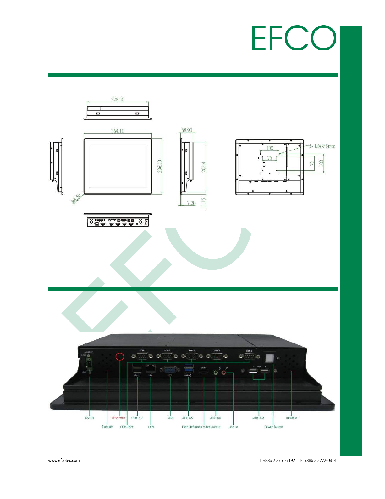
2.1 Dimension
Unit: mm
Phot_1 – TPC-5215 Dimension
2.2 Standard I/O Indication
2.2.1 I/O Indication View
Phot_2 – TPC-5215 I/O View
Page 20
9
Embedded System Touch Panel
PC
TPC-5215
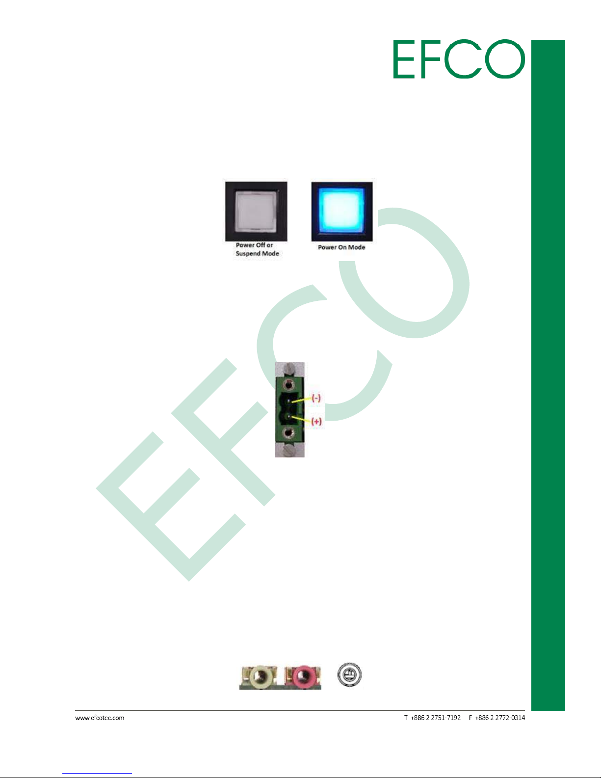
2.2.2 Power ON/OFF Button
The TPC-5215 has a Power On/Off button with LED indicator. Using the Power button,
the device can be switched on, suspended, shut down immediately, or shut down
with the delay of 4 seconds.
Photo_3 – Power Button
2.2.3 Power Input Connector
TPC-5215 comes with a DC 9V - 19V 2-pin terminal block connector.
Photo_4 – Power Input Connector
2.2.4 Speaker
TPC-5215 provides two 2W Speakers.
2.2.5 Audio Connector
TPC-5215 provides two 3.5mm ear phone jack connectors of Line-out and Line-out
function.
Photo_5 – Ear Phone Jack Connector
Page 21
10
Embedded System Touch Panel
PC
TPC-5215
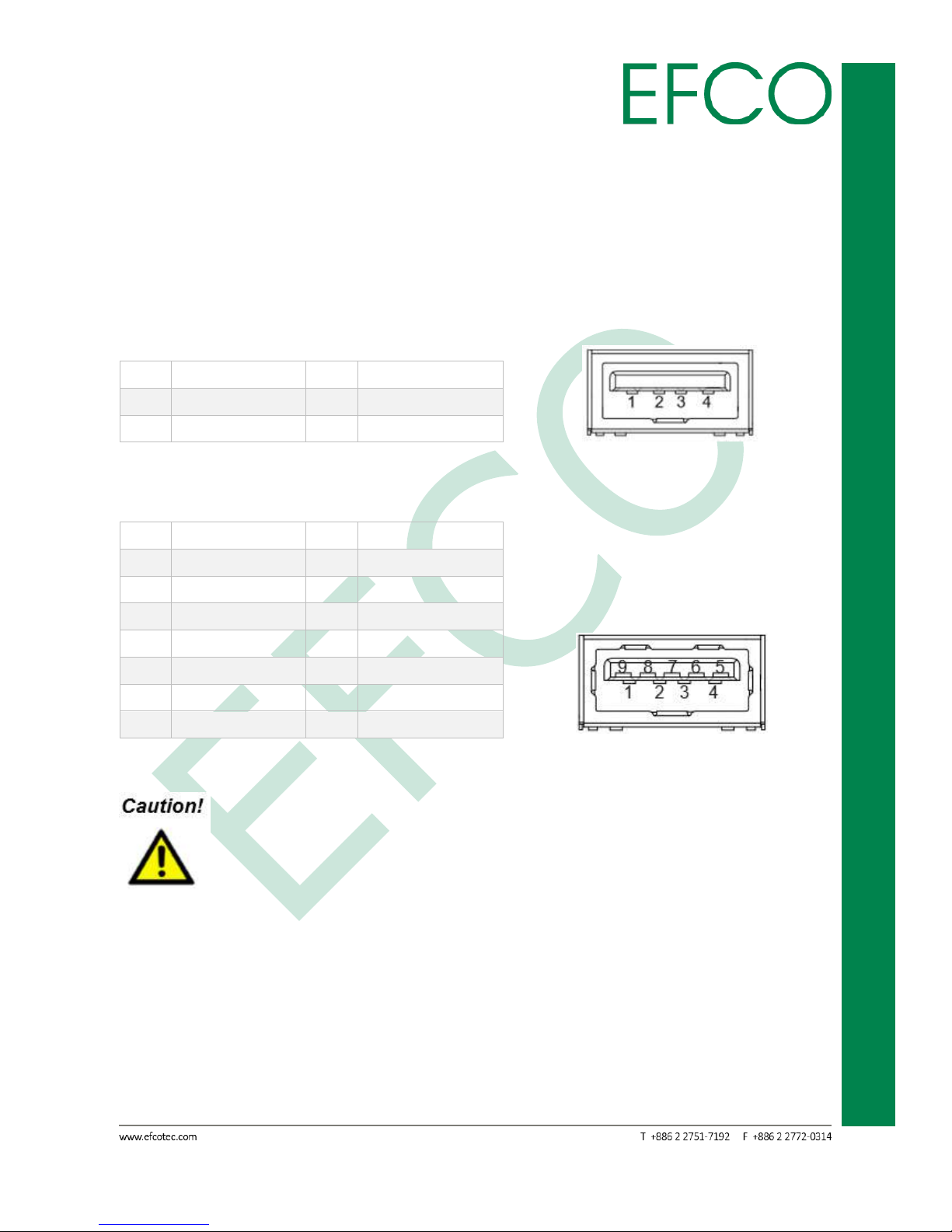
2.2.6 USB Connector
TPC-5215 provides six (4 x USB 2.0 & 2 x USB 3.0) USB interface connectors. The
interface is compliant with USB UHCI, Rev. 2.0 & 3.0. Both connectors are Plug and
Play compatible, allowing you to connect or disconnect a device whenever you want,
without turning off the computer.
USB 2.0
Pin
Signal Name
Pin
Signal Name
1
+5VSB
2
USB0_D-
3
USB0_D+
4
GND
Table_1 – USB 2.0 Pin Assignments Photo_6 – USB 2.0 Connector
USB 3.0
Pin
Signal Name
Pin
Signal Name
1
+5VSB
2
USB0_D-
3
USB0_D+
4
GND
5
USB1_SSRX-
6
USB1_SSRX+
7
GND
8
USB1_SSTX-
9
USB1_SSTX+
10
+5VSB
11
USB1_D-
12
USB1_D+
13
GND
Table_2 – USB 3.0 Pin Assignments Photo_7 – USB 3.0 Connector
When Insertion USB device, please check device's direction.
2.2.7 Ethernet Connector(LAN)
TPC-5215 provides a RJ-45 LAN interface connector which is fully compliant with IEEE
802.3u 10/100/1000 Mbps CSMA/CD standards. The Ethernet port uses a standard
RJ-45 jack connector with LED indicators on the front side to show Active/Link and
Speed status.
Page 22

11
Embedded System Touch Panel
PC
TPC-5215
Pin
Signal Name
Pin
Signal Name
1
TX+, MDI0+
2
TX-, MDI0-
3
RX+, MDI1+
4
MDI2+
5
MDI2-
6
RX-, MDI1-
7
MDI3+
8
MDI3-
Table_3 – LAN Pin Assignments Photo_8 – Ethernet Connector
LAN LED State Table
Activity/Link LED
SPEED LED
Status
Description
Status
Description
Off
No Link
Off
10Mbps connection
Blinking
Data Activity
Off
100Mbps connection
On
Link
Green
1Gbps connection
Table_4 – LAN LED State
2.2.8 VGA Connector
TPC-5215 provides a high resolution VGA interface through a 15-pin D-sub connector
in order to support a VGA CRT monitor. The maximum resolution is 1920 x 1080.
Pin
Signal Name
Pin
Signal Name
1
RED
2
GREEN
3
BLUE
4
NC 5 GND
6
GND
7
GND
8
GND
9
NC
10
GND
11
NC
12
DDC Date
13
H-Sync
14
V-Sync
15
DDC Clock
Table_5 – VGA Pin Assignments Photo_9 – VGA Connector
2.2.9 High definition video output Connector
TPC-5215 provides a high resolution High definition video output Port.
Pin
Signal Name
Pin
Signal Name
Page 23

12
Embedded System Touch Panel
PC
TPC-5215
1
TMDS Data2+
2
TMDS Data2 Shield
3
TMDS Data2–
4
TMDS Data1+
5
TMDS Data1 Shield
6
TMDS Data1–
7
TMDS Data0+
8
TMDS Data0 Shield
9
TMDS Data0–
10
TMDS Clock+
11
TMDS Clock Shield
12
TMDS Clock–
13
CEC
14
Reserved (N.C. on device)
15
SCL
16
SDA
17
DDC/CEC Ground
18
+5V Power
19
Hot Plug Detect
Table_6 – High definition video output Pin Assignments
Photo_10 – High definition video output Connector
2.2.10 COM Port
TPC-5215 provides five COM port headers. The product supports RS232/422/485 on
COM1 port. Please refer to below table for the pin definition. And COM2, 3, 4, 6 only
support (RS232).
COM1 Port Pin Definition
PIN
RS232
RS422
RS485
1
DCD
TX-
RTX-
2
RXD
RX+
N/A
3
TXD
TX+
RTX+
4
DTR
RX-
N/A
5
GND
GND
GND
6
DSR
N/A
N/A
7
RTS
N/A
N/A
8
CTS
N/A
N/A
9
+5V/+12V
+5V/+12V
+5V/+12V
10
NC
NC
NC
Table_7 – COM1 Port Pin Definition Photo_11 – COM Port I/O Pin
Page 24

13
Embedded System Touch Panel
PC
TPC-5215
COM1 port (RS232/422/485) can be adjusted in BIOS setup utility
Advanced Screen Super IO Configuration.
2.3 Expansion Slot
2.3.1 Expansion Slot location
Photo_12 – Expansion slot Location
Page 25
14
Embedded System Touch Panel
PC
TPC-5215
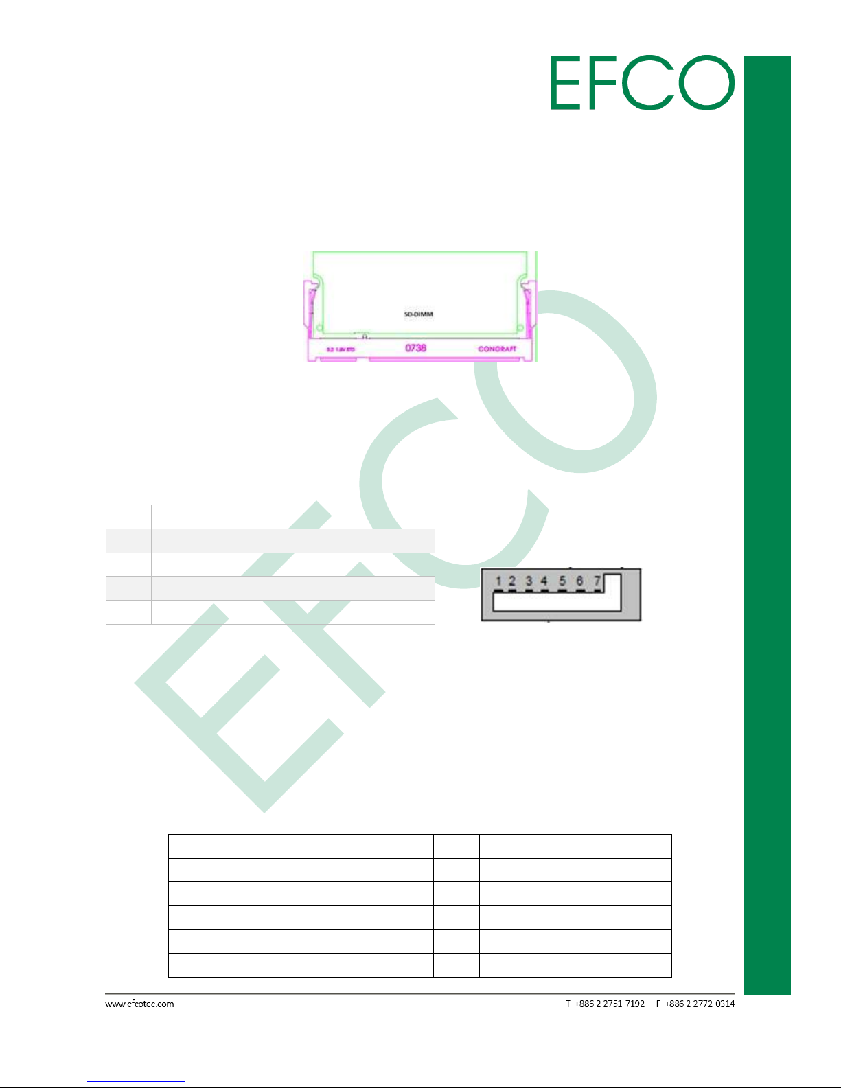
2.3.2 SO-DIMM Connector_①
TPC-5125 provides two 204-pin DDR3 (Double Data Rate 3) SO-DIMM slots, which
support Dual Channel DDR3L (low voltage). The memory max up to 8GB.
Photo_13 – Memory Slot
2.3.3 SATA 1 Connector_②
The TPC-5215 provides an SATA ports. The SATA ports support data rates up to 3GB/s.
Pin
Signal Name
Pin
Signal Name
1
GND
2
TX+
3
TX- 4 GND
5
RX-
6
RX+
7
GND
8
Table_8 – SATA Connector Pin Assignments Photo_14 – SATA connector
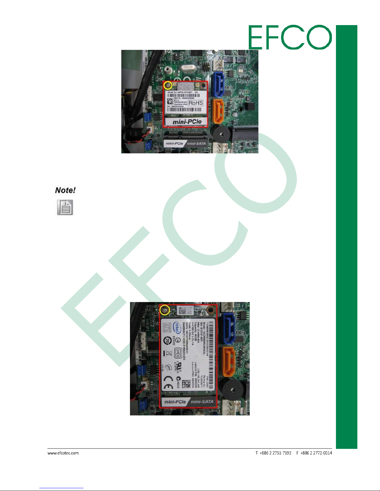
2.3.4 PCI Express Mini Card_③④
The TPC-5215 provides two PCI Express Mini Card (Full-Size x 1, Half-Size x 1). Full-Size
slot (③) is used for PCI Express mini cards or mSATA cards. This SATA signal is shared
with SATA2_2 connectors. Half-Size slot (④) is used for PCI Express mini cards.
Pin
Signal Name
Pin
Signal Name
1
WAKE#
2
+3.3V
3
NC 4 GND
5
NC 6 +1.5V
7
PCIE_CLK_REQ#
8
NC 9 GND
10
NC
Page 26

15
Embedded System Touch Panel
PC
TPC-5215
11
REFCLK-
12
NC
13
REFCLK+
14
NC
15
GND
16
NC
17
PULL DOWN RESISTOR(1M)
18
GND
19
NC
20
W_DISABLE#
21
GND
22
PERST#
23
PERn0
24
+3.3V
25
PERp0
26
GND
27
GND
28
+1.5V
29
GND
30
SMB_CLK
31
PETn0
32
SMB_DATA
33
PETp0
34
GND
35
GND
36
USB_D-
37
GND
38
USB_D+
39
+3.3V
40
GND
41
+3.3V
42
NC
43
mSATA_mPCIe_detect
44
NC
45
CL_CLK
46
NC
47
CL_DATA
48
+1.5V
49
CL_RST#
50
GND
51
NC
52
+3.3V
53
GND
54
GND
Table_9 – PCI Express Mini Card Slot Pin Assignments
Photo_15 – Full-Size mPCIe slot Photo_16 – Half-Size mPCIe slot
⑤
is Full-Size slot function select jumper. Default setting is 1-2。
Page 27

16
Embedded System Touch Panel
PC
TPC-5215
Photo_17 – Jumper setting
2.4 Hardware Install and Upgrades
Pre-installation Precautions
Take note of the following precautions before you install motherboard components
or change any motherboard settings.
1. Unplug the power cord from the wall socket before touching any component.
2. To avoid damaging the motherboard components due to static electricity, NEVER
place your motherboard directly on the carpet or the like. Also remember to use a
grounded wrist strap or touch a safety grounded object before you handle
components.
3. Hold components by the edges and do not touch the ICs.
4. Whenever you uninstall any component, place it on a grounded antistatic pad or
in the bag that comes with the component.
Before you install or remove any component, ensure that the power is
switched off or the power cord is detached from the power supply.
Failure to do so may cause severe damage to the motherboard,
peripherals, and/or components.
Do not over-tighten the screws! Doing so may damage the screw hole
and device.
2.4.1 Memory Module (SO-DIMM) Installation
1. Before installing any device, please make sure that the power supply is switched
off or the power cord is unplugged.
Page 28

17
Embedded System Touch Panel
PC
TPC-5215
Photo_18 – Power connector
2. Remove the system unit cover 8 (M3 x 4mm) screws.
Photo_19 – system unit cover 8 screws location
3. Open system unit cover.
Photo_20 – Open real chassis
Page 29

18
Embedded System Touch Panel
PC
TPC-5215
Please to pay heed the SATA cables. The cable be hook at real chassis.
4. Align a SO-DIMM on the slot such that the notch on the SO-DIMM matches the
break on the slot. Firmly insert the SO-DIMM into the slot until the retaining clips
at both ends fully snap back in place and the SO-DIMM is properly seated.
Photo_21 – RAM Slot
5. Replace the system cover.
1. If you install one memory module only, please install it on DDR3_A1.
2. It is not allowed to install a DDR or DDR2 memory module into a DDR3
slot; otherwise, this motherboard and SO-DIMM may be damaged.
3. Please make sure to disconnect the power supply before adding or
removing SO-DIMMs or the system components.
4. The SO-DIMM only fits in one correct orientation. It will cause
permanent damage to the motherboard and the SO-DIMM if you force
the SO-DIMM into the slot at incorrect orientation.
2.4.2 Half-Size PCI Express Mini Card Installation
1. The step 1 ~ 3 the same Memory installation.
2. Align the card connector with the slot and press firmly until the card is completely
seated on the slot. Fasten the card to the motherboard with screws (M2 x 4mm).
Page 30
19
Embedded System Touch Panel
PC
TPC-5215
Photo_22 – Half-size PCI Express Mini Card slot
3. Replace the system cover.
If machine have install Full-size mPCIe card, please remove Full-size
mPCIe card first. Then can see the Half-size mPCIe slot.
2.4.3 Full-Size PCI Express Mini Card Installation
1. The step 1 ~ 3 the same Memory installation.
2. Align the card connector with the slot and press firmly until the card is completely
seated on the slot. Fasten the card to the motherboard with screws (M2 x 4mm).
Photo_23 – Full-size PCI Express Mini Card slot
3. Replace the system cover.
Page 31

20
Embedded System Touch Panel
PC
TPC-5215
If want to remove or replace device, please unlock (M2 x 4mm) screws
first.
2.4.4 HDD replace or upgrade
1. Before installing any device, please make sure that the power supply is switched
off or the power cord is unplugged.
Photo_24 – Power connector
2. Remove the system unit cover 4 (M3 x 4mm) screws.
Photo_25 – system unit cover 4 screws location
3. Open system HDD cover and disconnect SATA and Power cables.
Page 32

21
Embedded System Touch Panel
PC
TPC-5215
Photo_26 – Open real chassis
4. Remove 4 (M3 x 4mm) screws to add or replace HDD.
Photo_27 – HDD location
5. Replace the system cover.
Page 33

22
Embedded System Touch Panel
PC
TPC-5215
2.5 Panel-mount Installation
To mount the panel onto a wall, you will need a strong mounting surface, screws,
along with the mounting brackets.
Please take a look at the illustration below before starting to mount the panel.
1. Prepare a 328.5mm x 265.4mm opening on the surface to be mounted.
Photo_28 – wall
2. Place the rear of the panel through the opening.
Photo_29 – Machine install
Page 34

23
Embedded System Touch Panel
PC
TPC-5215
3. There is a funnel-shaped track inside each of the mount holes on the panel. Insert
each mount into the holes from the wide end of the track and push it towards the
narrow end to secure. Do this for all the mounts.
Photo_30 – Mounts lock
4. Once all the mounts are secured, secure the panel itself by tightening the screws.
Photo_31 – Fix photo
Page 35

24
Embedded System Touch Panel
PC
TPC-5215
Chapter 3
BIOS SETUP
Page 36

25
Embedded System Touch Panel
PC
TPC-5215
3.1 BIOS Introduction
This section explains how to use the UEFI SETUP UTILITY to configure your system.
The UEFI chip on the motherboard stores the UEFI SETUP UTILITY. You may run the
UEFI SETUP UTILITY when you start up the computer. Please press <F2> or <Del>
during the Power-On-Self-Test (POST) to enter the UEFI SETUP UTILITY, otherwise,
POST will continue with its test routines.
If you wish to enter the UEFI SETUP UTILITY after POST, restart the system by pressing
<Ctrl> + <Alt> + <Delete>, or restart by turning the system off and then back on.
Because the UEFI software is constantly being updated, the following
UEFI setup screens and descriptions are for reference purpose only, and
they may not exactly match what you see on your screen.
Only experienced users should change the default BIOS settings!
Page 37

26
Embedded System Touch Panel
PC
TPC-5215
3.2 UEFI Menu Bar and Navigation Keys
EFCO TPC-5215 BIOS setup screen is composed of the menu bar, left frame and right
frame. The menu bar is shown below:
Item
Description
Main
To set up the system time/date information
Advanced
To set up the advanced UEFI features
H/W Monitor
To display current hardware status
Security
To set up the security features
Boot
To set up the default system device to locate and load
the Operating System
Exit
To exit the current screen or the UEFI SETUP UTILITY
Table_10 – BIOS Menu Bar
The left frame displays all the options that can be configured in the selected menu.
Grayed-out options cannot be configured. Only the blue options can be configured.
When an option is selected, it is highlighted in white.
The right frame displays the key legend. Above the key legend is an area reserved for
text messages. These text messages explain the options and the possible impacts
when changing the selected option in the left frame.
The setup program uses a key-based navigation system. Most of the keys can be used
at any time while in setup. The table below explains the supported keys:
Key
Description
← / →
Moves cursor left or right to select Screens
↑ / ↓
Moves cursor up or down to select items
+ / -
To change option for the selected items
ENTER
To bring up the selected screen
F1
To display the General Help Screen
F7
Discard changes
F9
To load optimal default values for all the settings
F10
To save changes and exit the UEFI SETUP UTILITY
F12
Print screen
ESC
To jump to the Exit Screen or exit the current screen
Table_11 – BIOS key control
Page 38

27
Embedded System Touch Panel
PC
TPC-5215
3.3 Main
When you enter the UEFI SETUP UTILITY, the Main screen will appear and display the
system overview. The system time and date item can be change. The Main BIOS Setup
page screen is shown below.
Photo_32 – Main Setting
Page 39

28
Embedded System Touch Panel
PC
TPC-5215
3.4 Advanced
In this section, you may set the configurations for the following items: CPU
Configuration, Chipset Configuration, Storage Configuration, Intel(R) Smart Connect
Technology, Super IO Configuration, ACPI Configuration and USB Configuration.
Photo_33 – Advanced Setting
Setting wrong values in this section may cause the system to
malfunction.
Page 40

29
Embedded System Touch Panel
PC
TPC-5215
3.4.1 CPU Configuration
Photo_34 – Advanced_CPU Configuration photo
Intel SpeedStep Technology: Intel SpeedStep technology is Intel’s new power saving
technology. Processors can switch between multiple
frequencies and voltage points to enable power saving.
Enabling this function may reduce CPU voltage and lead to system
stability or compatibility issues with some power supplies. Please set this
item to [Disabled] if above issues occur.
CPU C States Support: Enable CPU C States Support for power saving. It is
recommended to keep C3, C6 and C7 all enabled for better
power saving.
Enhanced Halt State (C1E): Enable Enhanced Halt State (C1E) for lower power
Page 41

30
Embedded System Touch Panel
PC
TPC-5215
consumption.
No-Execute Memory Protection: No-Execution (NX) Memory Protection Technology is
an enhancement to the IA-32 Intel Architecture. An
IA-32 processor with “No Execute (NX) Memory
Protection” can prevent data pages from being used
by malicious software to execute codes. This option
will be hidden if the current CPU does not support
No-Excute Memory Protection.
Intel Virtualization Technology: When this option is set to [Enabled], a VMM (Virtual
Machine Architecture) can utilize the additional
hardware capabilities provided by Vanderpool
Technology. This option will be hidden if the installed
CPU does not support Intel Virtualization Technology.
Function Item
Select Item
Intel SpeedStep Technology
Disabled
Enabled (Default setting)
CPU C States Support
C7 (Default setting)
C6
C1
Disabled
Enhanced Halt State (C1E)
Disabled
Enabled (Default setting)
No-Execute Memory Protection
Disabled
Enabled (Default setting)
Intel Virtualization Technology
Disabled
Enabled (Default setting)
Table_12 – Advanced_CPU Configuration setting
Page 42

31
Embedded System Touch Panel
PC
TPC-5215
3.4.2 Chipset Configuration
Photo_35 – Advanced_Chipset Configuration photo
DRAM Voltage: Configure the Voltage for the DRAM.
Primary Graphics Adapter: This allows you to select [Onboard] or [PCI Express] as the
boot graphic adapter priority.
Share Memory: Configure the size of memory that is allocated to the integrated
graphics processor when the system boots up.
Active LVDS: Use this to enable or disable the LVDS.
Enabling this function could be select "Panel Type Selection" item.
Panel Type Selection: Use this to select panel type.
Page 43

32
Embedded System Touch Panel
PC
TPC-5215
Please make sure your panel type at right setting. Wrong setting would
let panel no display.
If panel no display, please connect external monitor then reboot the
system.
Onboard HD Audio: Select [Auto], [Enabled] or [Disabled] for the onboard HD Audio
feature.
Front Panel: Select [Auto] or [Disabled] for the onboard HD Audio Front Panel.
Onboard HDMI HD Audio: This allows you to enable or disable the Onboard HDMI HD
Audio feature.
Onboard LAN 1: This allows you to enable or disable the Onboard LAN 1 feature.
PCIE1 Link Speed: Select the link speed for PCIE1.
Deep S5: Mobile platforms support Deep S5 in DC only and desktop platforms
support Deep S5 in AC only.
Function Item
Select Item
DRAM Voltage
Auto (Default setting)
1.35V
1.50V
Primary Graphics Adapter
Onboard
PCI Express (Default setting)
Share Memory
Auto (Default setting)
64MB
128MB
256MB
512MB
Active LVDS
Disabled (Default setting)
Enabled
Panel Type Selection
1366x768 / 18-bit / 1-ch / LED
800x600 / 18-bit / 1-ch / CCFL
1024x768 / 24-bit / 1-ch / CCFL
1280x1024 / 24-bit / 2-ch / CCFL
1366x768 / 24-bit / 1-ch / CCFL
1440x900 / 24-bit / 2-ch / CCFL
1024x600 / 18-bit / 1-ch / LED
1440x900 / 24-bit / 2-ch / LED (Default setting)
1280x1024 / 24-bit / 2-ch / LED
Page 44

33
Embedded System Touch Panel
PC
TPC-5215
1024x768 / 24-bit / 1-ch / LED
1600x900 / 18-bit / 2-ch / LED
1366x768 / 24-bit / 1-ch / LED
1920x1080 / 24-bit / 2-ch / LED
800x600 / 24-bit / 1-ch / LED
640x480 / 24-bit / 1-ch / LED
1024x768 / 18-bit / 1-ch / LED
Onboard HD Audio
VBIOS Default (Default setting)
CRT
HDMI
LVDS
Onboard HD Audio
Disabled
Enabled (Default setting)
Front Panel
Auto (Default setting)
Disabled
Onboard HDMI HD Audio
Disabled
Enabled (Default setting)
Onboard LAN 1
Enabled (Default setting)
Disabled
PCIE1 Link Speed
Auto (Default setting)
Gen 2
Gen 1
Deep S5
Auto
Disabled (Default setting)
Table_13 – Advanced_Chipset Configuration setting
Page 45

34
Embedded System Touch Panel
PC
TPC-5215
3.4.3 Storage Configuration
Photo_36 – Advanced_Storage Configuration photo
SATA Controller(s): Use this item to enable or disable the SATA Controller feature.
SATA Mode Selection: Use this to select SATA mode.
AHCI (Advanced Host Controller Interface) supports NCQ and other new
features that will improve SATA disk performance but IDE mode does not
have these advantages.
SATA Aggressive Link Power Mgmt: Use this item to configure SATA Aggressive Link
Power Management.
Hard Disk S.M.A.R.T: Use this item to enable or disable the S.M.A.R.T. (Self-
Monitoring, Analysis, and Reporting Technology) feature.
Page 46

35
Embedded System Touch Panel
PC
TPC-5215
Function Item
Select Item
SATA Controller(s)
Enabled (Default setting)
Disabled
SATA Mode Selection
IDE Mode
AHCI Mode (Default setting)
SATA Aggressive Link Power Mgmt
Disabled (Default setting)
Enabled
Hard Disk S.M.A.R.T
Disabled (Default setting)
Enabled
Table_14 – Advanced_Storage Configuration setting
SATA2_1:
Photo_37 – SATA2_1 setting photo
External SATA: Enable SATA safe removal notifications. Please note that the SATA
device will be downgraded to SATA2.
Page 47

36
Embedded System Touch Panel
PC
TPC-5215
Hot Plug: Enable or disable Hot Plug for this port.
Function Item
Select Item
External SATA
Disabled (Default setting)
Enabled
Hot Plug
Enabled
Disabled (Default setting)
Table_15 – SATA2_1 setting
SATA2_2 / mini-SATA:
Photo_38 – SATA2_1 setting photo
External SATA: Enable SATA safe removal notifications. Please note that the SATA
device will be downgraded to SATA2.
Hot Plug: Enable or disable Hot Plug for this port.
SATA LPM PLL Shutdown: Enable/Disable SATA LPM PLL Shutdown.
Page 48

37
Embedded System Touch Panel
PC
TPC-5215
Function Item
Select Item
External SATA
Disabled (Default setting)
Enabled
Hot Plug
Enabled
Disabled (Default setting)
SATA LPM PLL Shutdown
Enabled
Disabled (Default setting)
Table_16 – SATA2_2 / mini-SATA setting
Page 49

38
Embedded System Touch Panel
PC
TPC-5215
3.4.4 Intel(R) Smart Connect Technology
Photo_39 – Advanced_Intel(R) Smart Connect Technology photo
Intel(R) Smart Connect Technology: Use this item to enable or disable Intel(R) Smart
Connect Technology. Intel(R) Smart Connect
Technology keeps your e-mail and social networks,
such as Twitter, Facebook, etc. updated
automatically while the computer is in sleep mode.
Function Item
Select Item
Intel(R) Smart Connect Technology
Disabled (Default setting)
Enabled
Table_17 – Advanced_Intel(R) Smart Connect Technology Setting
Page 50

39
Embedded System Touch Panel
PC
TPC-5215
3.4.5 Super IO Configuration
Photo_40 – Advanced_Super IO Configuration photo
COM1 Configuration: Use this to set parameters of COM1. Select COM1 port type:
[RS232], [RS422] or [RS485].
COM2 Configuration: Use this to set parameters of COM2.
COM3 Configuration: Use this to set parameters of COM3.
COM4 Configuration: Use this to set parameters of COM4.
COM6 Configuration: Use this to set parameters of COM6.
LPT1 Port Configuration: Use this set parameters of the onboard parallel port.
CIR Controller Configuration: Use this set CIR controller.
WDT Timeout Reset: This allows users to enable/disable the Watch Dog Timer
timeout to reset system.
Page 51

40
Embedded System Touch Panel
PC
TPC-5215
COM1 Configuration
Function Item
Select Item
Serial Port
Disabled
Enabled (Default setting)
Type Select
RS232 (Default setting)
RS422
RS485
Table_18 – Advanced_Super IO Configuration_COM1 Setting
COM2/3/4/6 Configuration
Function Item
Select Item
Serial Port
Disabled
Enabled (Default setting)
Table_19 – Advanced_Super IO Configuration_COM2/3/4/6 Setting
LPT1 Port Configuration
Function Item
Select Item
LPT1 Port
Disabled
Enabled (Default setting)
Device Mode
Normal
Bi-Directional
ECP and EPP 1.9 Mode (Default setting)
ECP and EPP 1.7 Mode
Change Settings
Auto (Default setting)
IO=378h; IRQ=5; DMA=3;
IO=378h; IRQ=5,6,7,9,10,11,12; DMA=1,3;
IO=378h; IRQ=5,6,7,9,10,11,12; DMA=1,3;
Table_20 – Advanced_Super IO Configuration_LPT1 Setting
CIR Controller Configuration
Function Item
Select Item
CIR Controller
Disabled
Enabled (Default setting)
Table_21 – Advanced_Super IO Configuration_CIR Setting
Page 52

41
Embedded System Touch Panel
PC
TPC-5215
WDT Timeout Reset
Function Item
Select Item
WDT Timeout Reset
Disabled (Default setting)
Enabled
Table_22 – Advanced_Super IO Configuration Setting
3.4.6 ACPI Configuration
Photo_41 – Advanced_ACPI Configuration photo
Suspend to RAM: Use this item to select whether to auto-detect or disable the Suspend
-to-RAM feature
ACPI HPEL Table: Use this item to enable or disable ACPI HPET Table. Please set this
option to [Enabled] if you plan to use this motherboard to submit
Windows® certification.
PS/2 Keyboard Power On: Use this item to enable or disable PS/2 keyboard to turn on
Page 53

42
Embedded System Touch Panel
PC
TPC-5215
the system from the power-soft-off mode.
PCIE Devices Power On: Use this item to enable or disable PCIE devices to turn on the
system from the power-soft-off mode.
CIR Power On: Use this item to enable or disable CIR to power on the system.
RTC Alarm Power On: Use this item to enable or disable RTC (Real Time Clock) to power
on the system.
USB Keyboard/Remote Power On: Use this item to enable or disable USB Keyboard/
Remote to power on the system.
USB Mouse Power On: Use this item to enable or disable USB Mouse to power on the
system.
Function Item
Select Item
Suspend to RAM
Disabled
Auto (Default setting)
ACPI HPEL Table
Enabled (Default setting)
Disabled
PS/2 Keyboard Power On
Disabled (Default setting)
Any Key
PCIE Devices Power On
Disabled (Default setting)
Enabled
CIR Power On
Disabled (Default setting)
Enabled
RTC Alarm Power On
Disabled
Enabled
By OS (Default setting)
USB Keyboard/Remote Power On
Disabled (Default setting)
Enabled
USB Mouse Power On
Disabled (Default setting)
Enabled
Table_23 – Advanced_ACPI Configuration Setting
Page 54

43
Embedded System Touch Panel
PC
TPC-5215
3.4.7 USB Configuration
Photo_42 – Advanced_USB Configuration photo
USB Controller: Use this item to enable or disable the use of USB controller.
USB 3.0 Controller: Use this item to enable or disable the use of USB 3.0 controller.
If you enable “CSM “, USB 3.0 controller will be disabled when you
select [Auto]. If you disable “CSM “, USB 3.0 controller will be
enabled when you select [Auto].
Legacy USB Support: Use this option to select legacy support for USB devices. Please
refer to below descriptions for the details of these four options:
[Enabled] - Enables support for legacy USB.
[Auto] - Enables legacy support if USB devices are connected.
[UEFI Setup Only] - USB devices are allowed to use only under
UEFI setup and Windows / Linux OS.
Page 55

44
Embedded System Touch Panel
PC
TPC-5215
Function Item
Select Item
USB Controller
Enabled (Default setting)
Disabled
USB 3.0 Controller
Enabled
Disabled
Auto (Default setting)
Smart Auto
Legacy USB Support
Enabled (Default setting)
Auto
UEFI Setup Only
Table_24 – Advanced_USB Configuration Setting
3.4.8 Instant Flash
Photo_43 – Advanced_Instant Flash photo
Page 56

45
Embedded System Touch Panel
PC
TPC-5215
Save UEFI files in your USB storage device and run Instant Flash to update your UEFI.
Please note that your USB storage device must be FAT32/16/12 or NTFS file system.
Only root directory is working on NTFS drive.
Page 57

46
Embedded System Touch Panel
PC
TPC-5215
3.5 H/W Monitor
In this section, it allows you to monitor the status of the hardware on your system,
including the parameters of the CPU temperature, motherboard temperature, CPU
fan speed, chassis fan speed, and the critical voltage.
Photo_44 – H/W Monitor photo
CPU_FAN1 Setting: This allows you to set CPU_FAN1’s speed. Configuration options:
[Full On] and [Automatic Mode]
CHA_FAN1 Setting: This allows you to set CHA_FAN1’s speed. Configuration options:
[Full On] and [Automatic Mode].
Case Open Feature: This allows you to enable or disable case open detection feature.
Function Item
Select Item
CPU_FAN1 Setting
Full On (Default setting)
Page 58

47
Embedded System Touch Panel
PC
TPC-5215
Automatic Mode
CHA_FAN1 Setting
Full On (Default setting)
Automatic Mode
Case Open Feature
Disabled (Default setting)
Enabled
Table_25 – H/W Setting
Page 59

48
Embedded System Touch Panel
PC
TPC-5215
3.6 Security
In this section, you may set, change or clear the supervisor/user password for the
System.
Photo_45 – Security photo
Supervisor Password: Set or change the password for the administrator account. Only
the administrator has authority to change the settings in the
UEFI Setup Utility. Leave it blank and press enter to remove the
password.
User Password: Set or change the password for the user account. Users are unable to
change the settings in the UEFI Setup Utility. Leave it blank and press
enter to remove the password.
Secure Boot: Enable to support Windows 8 64-bit Secure Boot.
Page 60

49
Embedded System Touch Panel
PC
TPC-5215
3.7 Boot
In this section, it will display the available devices on your system for you to configure
the boot settings and the boot priority.
Photo_46 – Boot photo
Boot Option #1: Set the system boot order.
Hard Drive BBS Priorities: Set the order of the legacy devices in this group.
Fast Boot: Fast Boot minimizes your computer’s boot time. There are three con
figuration options: [Disabled], [Fast] and [Ultra Fast]. Please refer to below
descriptions for the details of these three options:
[Disabled] - Disable Fast Boot.
[Fast] - The only restriction is you may not boot by using an USB flash drive.
[Ultra Fast] - There are a few restrictions.
1. Only supports Windows® 8 64-bit UEFI operating system.
2. You will not be able to enter BIOS Setup (Clear CMOS or run
utility in Widows® to enter BIOS Setup).
Page 61

50
Embedded System Touch Panel
PC
TPC-5215
3. If you are using an external graphics card, the VBIOS must
support UEFI GOP in order to boot.
Boot From Onboard LAN: Use this item to enable or disable the Boot From Onboard
LAN feature.
Setup Prompt Timeout: This shows the number of seconds to wait for setup activation
key.
Bootup Num-Lock: If this item is set to [On], it will automatically activate the Numeric
Lock function after boot-up.
Boot Beep: Select whether the Boot Beep should be turned on or off when the system
boots up. Please note that a buzzer is needed.
Full Screen Logo: Use this item to enable or disable OEM Logo.
AddOn ROM Display: Set display mode for Option ROM.
Function Item
Select Item
Fast Boot
Disabled (Default setting)
Fast
Ultra Fast
Boot From Onboard LAN
Disabled (Default setting)
Enabled
Bootup Num-Lock
On
Off
Boot Beep
Disabled (Default setting)
Enabled
Full Screen Logo
Disabled
Enabled (Default setting)
AddOn ROM Display
Enabled (Default setting)
Disabled
Table_26 – Boot Setting
3.7.1 CSM (Compatibility Support Module)
Enable to launch the Compatibility Support Module. Please do not disable unless
you’re running a WHCK test. If you are using Windows® 8 64-bit and all of your
devices support UEFI, you may also disable CSM for faster boot speed.
Page 62

51
Embedded System Touch Panel
PC
TPC-5215
Photo_47 – Boot_CSM photo
Function Item
Select Item
CSM
Disabled (Default setting)
Enabled
Launch PXE OpROM policy
Do not launch
UEFI only
Legacy only (Default setting)
Launch Storage OpROM policy
Do not launch
UEFI only
Legacy only (Default setting)
Launch Video OpROM policy
Do not launch
UEFI only
Legacy only (Default setting)
Table_27 – Boot_CSM Setting
Page 63

52
Embedded System Touch Panel
PC
TPC-5215
3.8 Exit
Photo_48 – Exit photo
Save Changes and Exit: Exit system setup after saving the change. “F10” key can be
used for this operation.
Discard Changes and Exit: Exit system setup without saving any change. “ESC” key can
be used for this operation.
Discard Changes: Discard changes done so far to any of the setup options. “F7” key can
be used for this operation.
Load UEFI Defaults: Load UEFI default values for all the setup questions. “F9” key can
Be used for this operation.
Launch EFI Shell from filesystem device: Attempts to Launch EFI Shell application
(Shell64.efi) from one of the available
filesystem devices.
Page 64

53
Embedded System Touch Panel
PC
TPC-5215
Chapter 4
DRIVER INSTALLATION
Page 65

54
Embedded System Touch Panel
PC
TPC-5215
4.1 Driver Installation
The TPC-5215 comes with a product DVD. That contains user's manual and all drivers
to help your setup product. Insert the DVD and follow the steps in the auto run
program to install the drivers.
In case the program does not start, follow the sequence below to install the drivers.
Step 1 – Install Chipset Driver
1. Open the “STEP1 – 01.Chipset” folder followed by “Setup.exe”.
2. Follow the instructions.
3. Drivers will be installed automatically.
Step 2 – Install Intel Smart Connect Driver
1. Open the “STEP2 – 02.Intel Smart Connect” folder followed by “Setup.exe”.
2. Follow the instructions.
3. Drivers will be installed automatically.
Before install driver, please change Intel Smart Connect setting to
“Enabled” at the BIOS.
Step 3 – Install Intel Sideband Fabric Driver (MBI)
1. Open the “STEP3 – 03.Intel Sideband Fabric Device” folder followed by
“Setup.exe”.
2. Follow the instructions.
3. Drivers will be installed automatically.
Step 4 –Install Intel Trusted Execution Engine Driver (TXE)
1. Open the “STEP4 – 04.Intel Trusted Execution Engine” folder followed by
“SetupTXE.exe”.
2. Follow the instructions.
3. Drivers will be installed automatically.
Step 5 – Install Graphic Driver
1. Open the “STEP5 – 05.Graphic” folder and select your OS.
2. Open the “Setup.exe” file in the folder.
3. Follow the instructions.
4. Drivers will be installed automatically.
Page 66

55
Embedded System Touch Panel
PC
TPC-5215
Step 6 – Install Audio Driver
1. Open the “STEP6 – 06.Audio” folder followed by “Setup.exe”.
2. Follow the instructions.
3. Drivers will be installed automatically.
Step 7 – Install COM Driver
1. Open the “STEP7 – 07.COM” folder and followed by “NuvSerial
v1.0.2011.1109 (WHQL).exe”.
2. Follow the instructions.
3. Drivers will be installed automatically.
Step 8 –Install LAN Driver
1. Open the “STEP8 – 08.LAN” folder and select your OS.
2. Open the “Setup.exe” file in the folder.
3. Follow the instructions.
4. Drivers will be installed automatically.
Step 9 – Install USB 3.0 Driver
1. Open the “STEP9 – 09.USB30” folder followed by “Setup.exe”.
2. Follow the instructions.
3. Drivers will be installed automatically.
Step 10 – Install CIR Driver
1. Open the “STEP10 – 10.CIR” folder followed by “Setup.exe”.
2. Follow the instructions.
3. Drivers will be installed automatically.
Page 67

56
Embedded System Touch Panel
PC
TPC-5215
Chapter A
I/O INFORMATION
Page 68

57
Embedded System Touch Panel
PC
TPC-5215
B.1 I/O Address Map
Photo_76 – I/O address map
Page 69
58
Embedded System Touch Panel
PC
TPC-5215
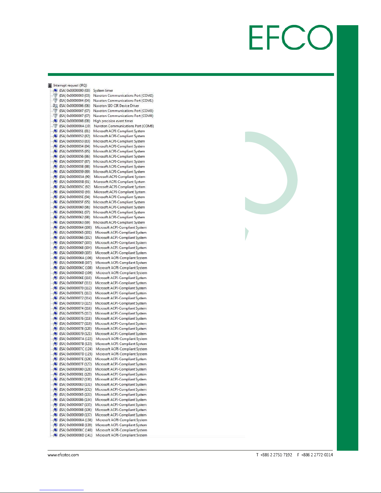
B.2 IRQ Mapping Chart
Photo_77 – IRQ Mapping Chart_1
Page 70

59
Embedded System Touch Panel
PC
TPC-5215
Photo_78 – IRQ Mapping Chart_2
Page 71

60
Embedded System Touch Panel
PC
TPC-5215
B.3 Memory Address Mapg
Photo_80 – Memory address map
 Loading...