

Page 1

S
e
5
Sliding glass door
ries 3000, 3001, 3014, 3015, 300
Installation Instructions
Part NO. YW41
February 2013
Page 2

SLIDING GLASS DOOR INSTALLATION INSTRUCTIONS
TABLE OF CONTENTS
Page
I. Sliding Glass Door General Overview
A. General Notes 3
B. Construction Notes 4
C. Building Codes 5
D. General Sliding Glass Door Frame Installation 5
E. Perimeter Anchorage 7
F. General Sliding Panel Inspection 8
II. Basic Sliding Glass Door Installation
A. Installation Without Subframe 9
B. Installation With Subframe 12
III. Series Specific Assembly Instructions
A. S-2000/3000 17
B. S-3001/3000 Modified 25
C. S-3015 33
D. S-3014 42
E. S-3005 51
Minimizing Condensation
Note: Please reference EFCO's "Understanding Condensation" brochure which can be obtained through your
EFCO representative.
Condensation will form on any surface when unfavorable conditions (interior temperature and relative
humidity and exterior temperature) are present. When the formation of excessive condensation is a concern, it is
highly recommended that a design professional is utilized to perform an analysis of the shop drawings to
recommend the best possible installation methods. Please contact your EFCO representative for information on
EFCO's Thermal Analysis Services.
Many current installation practices lead to an increase in the possibility of the formation of condensation.
Though not all inclusive, the list of examples below illustrates conditions under which condensation is likel y to occur:
1. Bridging system thermal break with non-thermally broken metal flashing or lintels that are exposed
to the exterior
2. System exposure to cold air cavities
3. Interior relative humidity levels not maintained at recommended levels, see EFCO’s “Understanding
Condensation” brochure
4. Inadequate separation between system and surrounding condition at perimeter
5. Product combinations during the shop drawing stage that result in bridging ther mal breaks
of one or all products involved
EFCO CORPORATION 6/8/2012 PART NO. YW41 Page 2 of 59
Page 3

pp
SLIDING GLASS DOOR INSTALLATION INSTRUCTIONS
These recommendations are for general erection procedures only. For actual job conditions,
see the details on the shop drawings. For perimeter anchor type and spacing, refer to the
a
roved shop drawings or consult the project design professional.
SECTION I: Sliding Glass Door General Overview
Sliding Glass Doors are disassembled products and must be protected against damage. The
following procedures and precautions are recommended:
A. General Notes
1. Protection and Storage
a. Handle the material carefully.
b. To avoid racking or damage to glazed panels and all Sliding Glass Door components
and accessories, do not drop or drag from the truck.
c. Stack the Sliding Glass Door panels with the directional arrows in the proper position
to allow adequate separation so the door panels will not rub together.
d. Store the Sliding Glass Door panels and accessories off the ground (i.e., pallets,
planks, etc.).
e. Protect against the elements and other construction trades by using a well ventilated
covering.
f. Remove material from packaging if it becomes wet. Then repack materials and move
to dry location.
g. Sliding Glass Doors are not to be used as ladders, scaffolds, or scaffold supports.
2. Check Materials
a. Check all the material upon arrival for quantity and damage. Any visibly damaged
material must be noted on the freight bill at the time of receipt. If a claim is required,
the receiving party must process a claim with the freight carrier. If the delivery is by an
EFCO truck, any damage or variance in the quantity of window units or boxes must be
reported to the EFCO driver during the unloading process.
3. Cleaning Door Units
a. Cement, plaster, terrazzo, alkaline, and acid based materials used to clean masonry
are very harmful to finishes and should be removed with water and mild soap
immediately; otherwise, permanent staining will occur. A spot test is recommended
before any cleaning agent is used.
b. For cleaning of anodized aluminum surfaces, refer to AAMA 609-93 Voluntary Guide
Specification for Cleaning and Maintenance of Architectural Anodized Aluminum.
c. For cleaning of painted aluminum surfaces, refer to AAMA 610.1-1979 Voluntary
Guide Specification for Cleaning and Maintenance of Painted Aluminum Extrusions
and Curtain Wall Panels.
Please note:
products to painted aluminum surfaces will induce permanent bonding of the tape to
the paint. This will cause adhesion failure between the paint and the aluminum
surface when the tape is removed.
d. If a protective coating is specified, remove it in areas that require field-applied sealant
prior to installation.
The prolonged application of masking tape, duct tape, and similar
EFCO CORPORATION 6/8/2012 PART NO. YW41 Page 3 of 59
Page 4

SLIDING GLASS DOOR INSTALLATION INSTRUCTIONS
B. Construction Notes
1. Reference Shop Drawings
a. Check the shop drawings and installation instructions to become thoroughly familiar
with the project. The shop drawings take precedence and include specific details for
the project. The installation instructions are general in nature and cover most common
conditions.
2. Check Openings
a. Make certain that construction, which will receive the material, is in accordance with
the contract documents. If not, notify the general contractor in writing and resolve
differences before proceeding with your work.
3. Benchmark Layout
a. All work should start from benchmarks and/or column center lines as established by
the architectural drawings and the general contractor.
4. Plumb/Level/True
a. All materials are to be installed plumb, level, true, and in proper alignment and relation
to established lines and grades. Products are to be installed maintaining tolerances of
1/8” in 12’-0” of length.
5. Isolate Aluminum
a. Isolate aluminum that directly contacts masonry or incompatible materials with a heavy
coat of zinc chromate, plastic isolators, or bituminous paint.
6. Poured and Debridged and Thermal Strut Sections
a. Do not drill, punch, penetrate, or alter the poured and debridged thermal break or
extruded thermal strut in any manner.
7. Fastening
a. Fastening means any method of securing one part to another or to adjacent materials.
Due to varying opening conditions, window configurations, design pressures, and
methods of anchorage (subframe, “F” anchors, etc.), perimeter fasteners are not
specified in these instructions. For anchor fastening, refer to the shop drawings or
consult the project design professional.
8. Blocking
a. All blocking and shims will be high strength plastic or non-corrosive materials, Not by
EFCO. Blocking must be of sufficient size and shape to support the frame at all
anchorage locations. The blocking must prevent the anchorage fasteners from
bowing, racking, twisting, or distorting the window frames and accessories in any
manner.
9. Sealant
a. Sealants must be compatible with all materials they contact, including other sealant
surfaces. Any sealant details shown herein, unless specifically called out to by EFCO,
are by others.
It is not EFCO Corporation’s position to select or recommend sealant or caulking types
and will not assume liability or responsibility thereof. Consult the sealant supplier for
recommendations relative to compatibility, adhesion, priming, tooling, shelf life, and
joint design. It is the sole responsibility of the customer to perform all sealant adhesion
and compatibility testing that is required by the sealant manufacturer of choice.
EFCO CORPORATION 6/8/2012 PART NO. YW41 Page 4 of 59
Page 5
SLIDING GLASS DOOR INSTALLATION INSTRUCTIONS
C. Building Codes
1. Glass and glazing codes governing the design and use of products vary widely. EFCO does
not control the selection of product configurations, operating hardware, or glazing materials;
therefore, we assume no responsibility in these areas. It is the responsibility of the owner,
architect, and the installer to make these selections in strict conformity to all applicable
codes.
D. General Sliding Glass Door Frame Installation
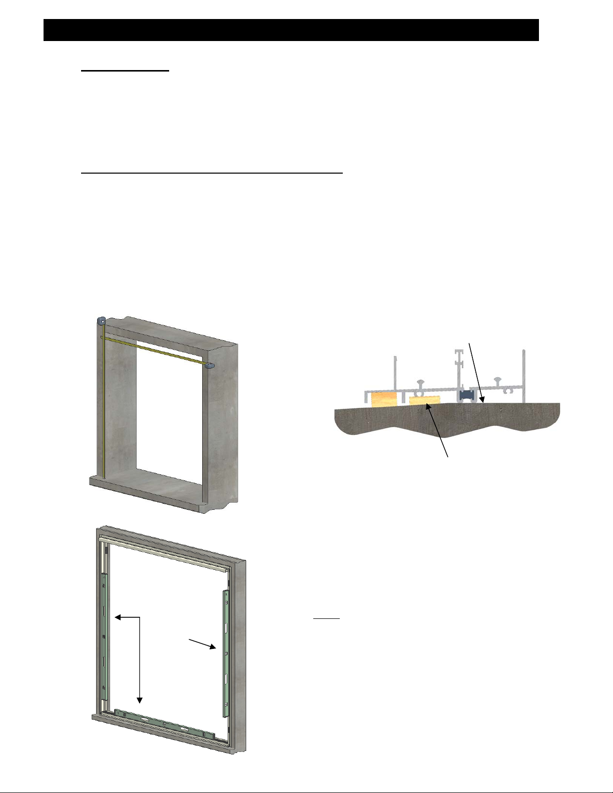
1. The rough opening should be checked for the correct size as determined by tolerances
listed in the architectural specifications and the shop drawings. (FIG. “A”)
2. Establish the face of the Sliding Glass Door line at the head, sill, and jambs. This reference
is to be arrived at by using the architectural plans, general contractor’s reference lines, and
shop drawings.
3. Determine the high point of the masonry sill using string line or transit and shim the balance
of the opening to match. (Fig. “B”)
Fig. “A”
Plumb
Frame
Fig. “B”
Note:
For proper Sliding Glass Door operation
and drainage it must be installed PLUMB and
LEVEL.
High
Shim at Anchor
Locations
EFCO CORPORATION 6/8/2012 PART NO. YW41 Page 5 of 59
Page 6
SLIDING GLASS DOOR INSTALLATION INSTRUCTIONS
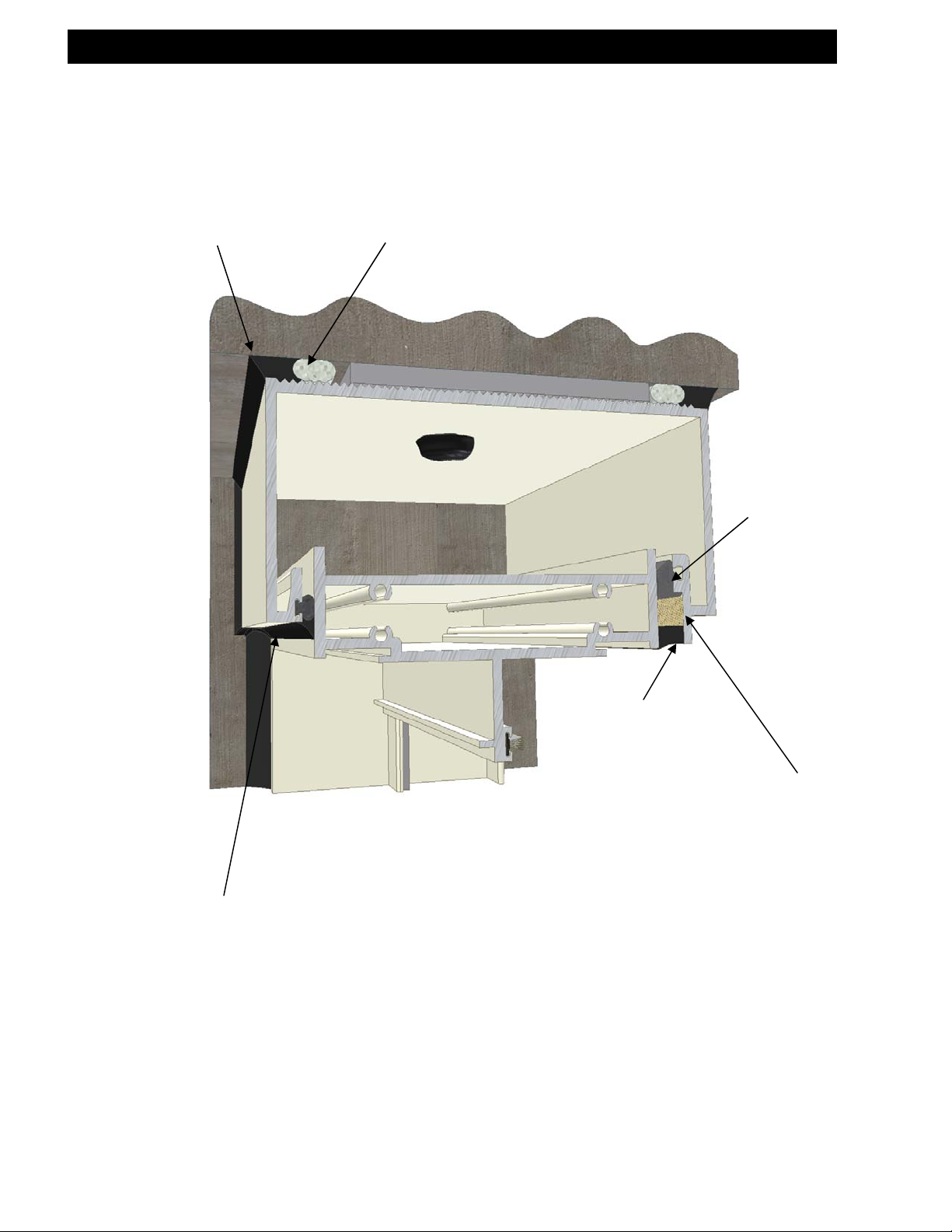
4. Do not fasten drapery tracks, ceiling supports, or convector covers to Sliding Glass Doors.
The Sliding Glass Door must be free to contract and expand.
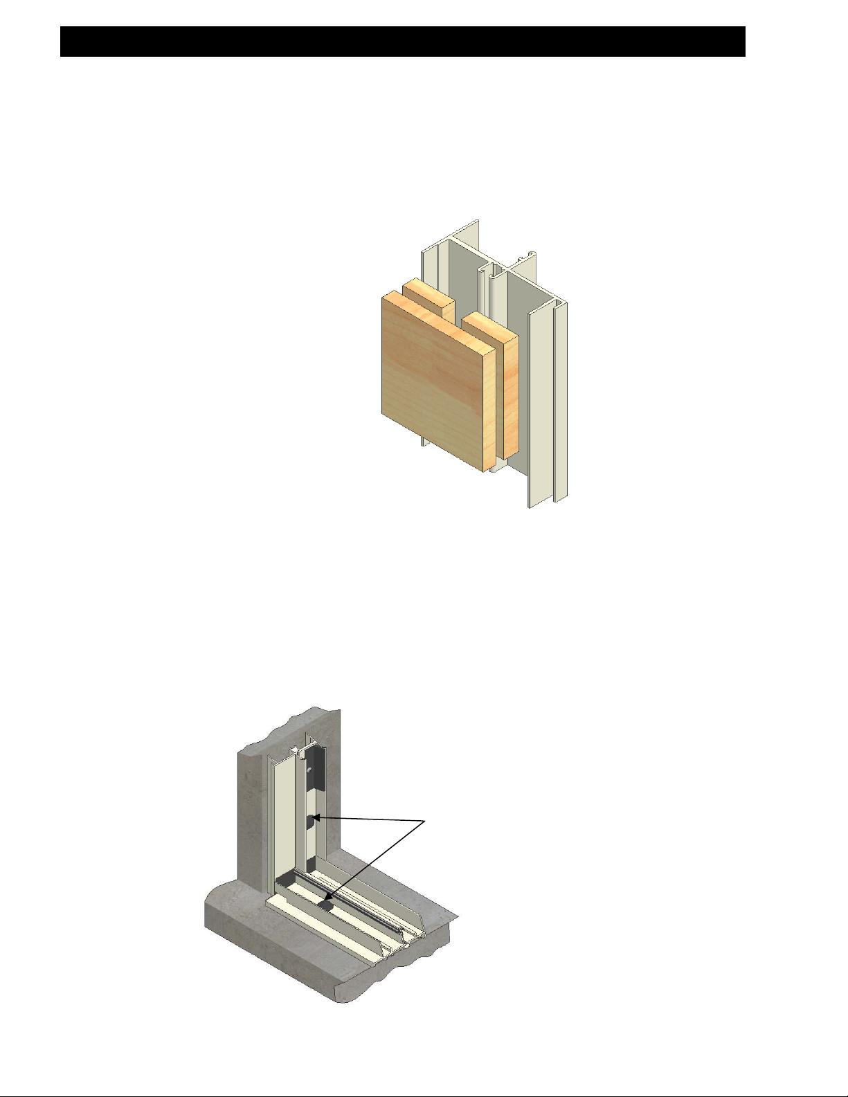
5. Install blocking in the Sliding Glass Door frame at anchor locations. All blocking and shims
will be high strength plastic or non-corrosive materials, Not by EFCO. (Fig. “C”)
6. Seal all exposed perimeter joints between structure and door frame perimeters with a
skinning, non-hardening type of sealant. Refer to the approved shop drawings for joint
design.
Seal all frame to frame and frame to accessory (subframe, panning, mullions) joints with
compatible silicone sealant. Refer to the approved shop drawings for joint design.
7. Seal all anchor heads along the sill and 6” up the jambs.
Fig. “D”
Fig. “C”
Sealant on anchor heads
EFCO CORPORATION 6/8/2012 PART NO. YW41 Page 6 of 59
Page 7
y
SLIDING GLASS DOOR INSTALLATION INSTRUCTIONS
E. Perimeter Anchorage
1. From the approved shop drawings, determine the size, type, and quantity of perimeter
fasteners required. EFCO will provide fasteners for EFCO material to EFCO material only.
All perimeter fasteners are not by EFCO and should be purchased prior to arriving at the job
site. (If subframe is used, please refer to the Subframe Installation sheets.)
Due to varying opening conditions, window configurations, design pressures, and methods
of anchorage (subframe, “F” anchors, etc.), perimeter fasteners are not specified in these
instructions. For perimeter anchor type and spacing, refer to the approved shop drawings or
consult the project design professional. The design professional should analyze the
anchorage system, and take into account the following information.
a. Frame dimensions and configuration of the as installed door.
b. Material properties of the door frame.
c. Allowable tension, shear, and bending properties of the perimeter fastener.
d. Design pressure.
e. Details of the surrounding condition for the head, sill, and jambs.
f. Relative building movements and expected thermal movement of the door system.
Perimeter
Fastener
Substrate
Edge
Distance
Bearing
Surface
Edge
Distance
Substrate
Edge
Distance
Bearing
Surface
Edge
Distance
Substrate
Thickness
Shim
Height
Note: This sketch is a typical
representation, other anchorage
s
stems will require similar information.
Frame
Edge
Distance
EFCO CORPORATION 6/8/2012 PART NO. YW41 Page 7 of 59
Frame
Edge
Distance
Page 8

SLIDING GLASS DOOR INSTALLATION INSTRUCTIONS
2. Perimeter anchors should never penetrate a tank or tubular shape at a window sill. Any
penetration of the frame must be visible for sealing purposes.
3. Blocking must be of sufficient size and shape to support the frame at all anchorage
locations. The blocking must prevent the anchorage fasteners from bowing, racking,
twisting, or distorting the window frames and accessories in any manner. Excessive shim
heights could increase the prying tension and/or bending forces on the perimeter fastener.
Refer to the approved shop drawings and/or design professional for project specific
applications.
F. General Sliding Panel Inspection
1. Upon completion of the Sliding Glass Door installation, all operating panels must be
checked for proper alignment and operation. If the sliding panels are removed, care must
be taken to ensure that sliding panels are reinstalled into the same frames they were
removed from. It may be necessary to adjust the rollers and locking hardware to ensure
proper sealing and locking. All hardware must be cleaned as necessary to provide smooth
operation.
EFCO CORPORATION 6/8/2012 PART NO. YW41 Page 8 of 59
Page 9

SLIDING GLASS DOOR INSTALLATION INSTRUCTIONS
SECTION II: Basic Sliding Glass Door Installation
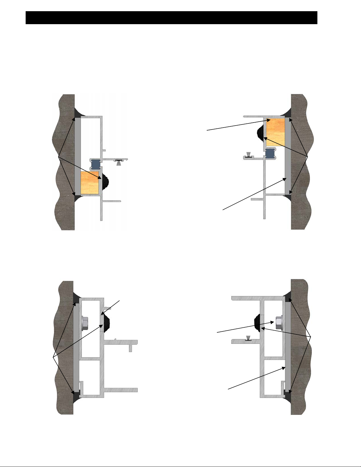
A. Installation Without Subframe
1. Assemble the Sliding Glass Door frame per the assembly instructions for the appropriate
Sliding Glass Door series.
EFCO Sliding Glass Doors, without a tank at the sill, may be anchored without the use of a
starter sill. This is because sealant can be applied over the head of the anchor. (A tankdesigned sill will not allow this option.) The sliding door sill may be anchored in the exterior
track or the interior track. Locating the anchor in the exterior or interior track would need the
consideration of minimum edge distance, the substrate to which the sills are being
anchored, or anything that would govern the best location for the anchor. (Fig. E & F)
Fig. “E”
Sealant
S-2000
Erector to Field
Drill for Anchors
Blocking by Erector
High Impact Shim by
Erector
S-3000
Erector to Field
Drill for Anchors
Fig. “F”
Blocking by Erector
High Impact Shim by
Erector
Sealant
EFCO CORPORATION 6/8/2012 PART NO. YW41 Page 9 of 59
Page 10
SLIDING GLASS DOOR INSTALLATION INSTRUCTIONS
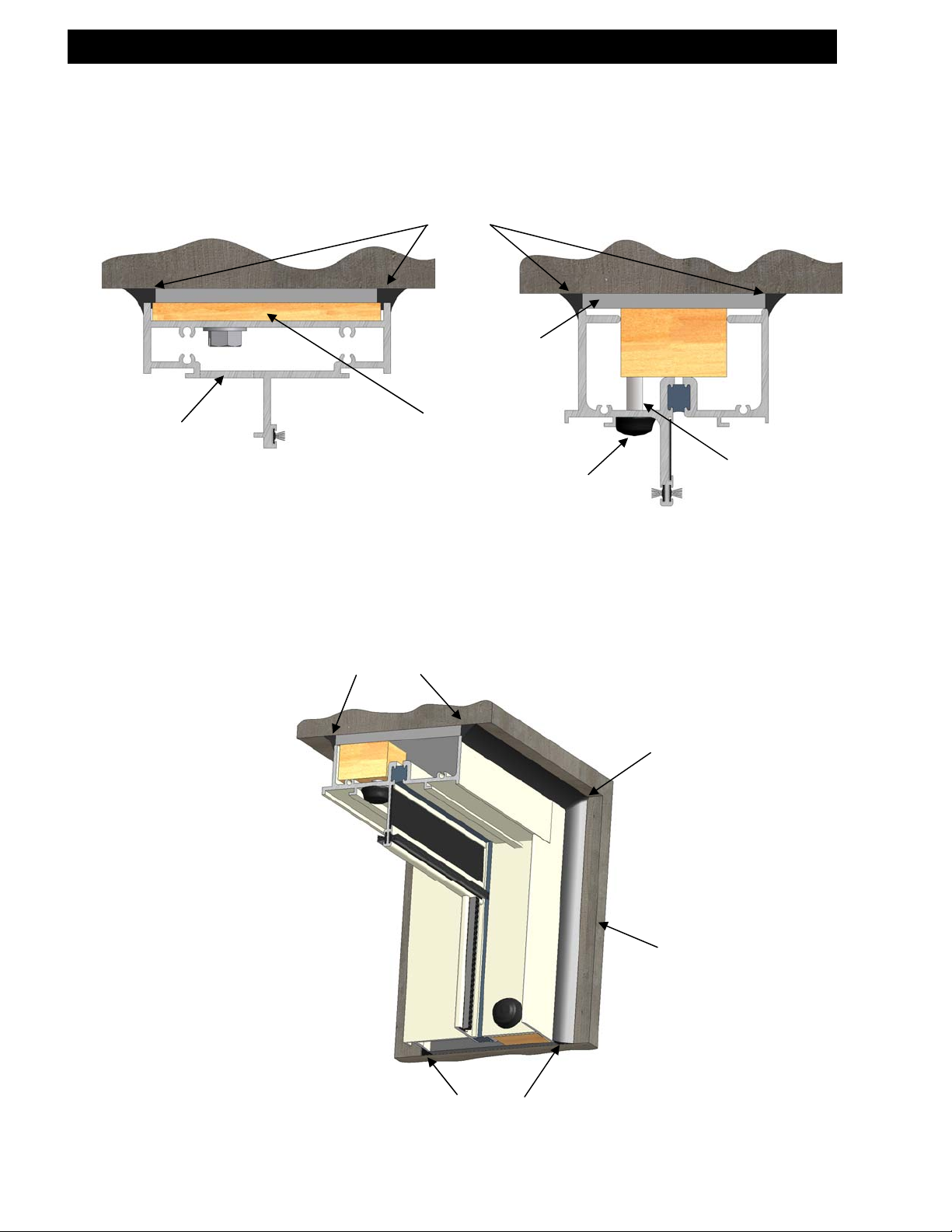
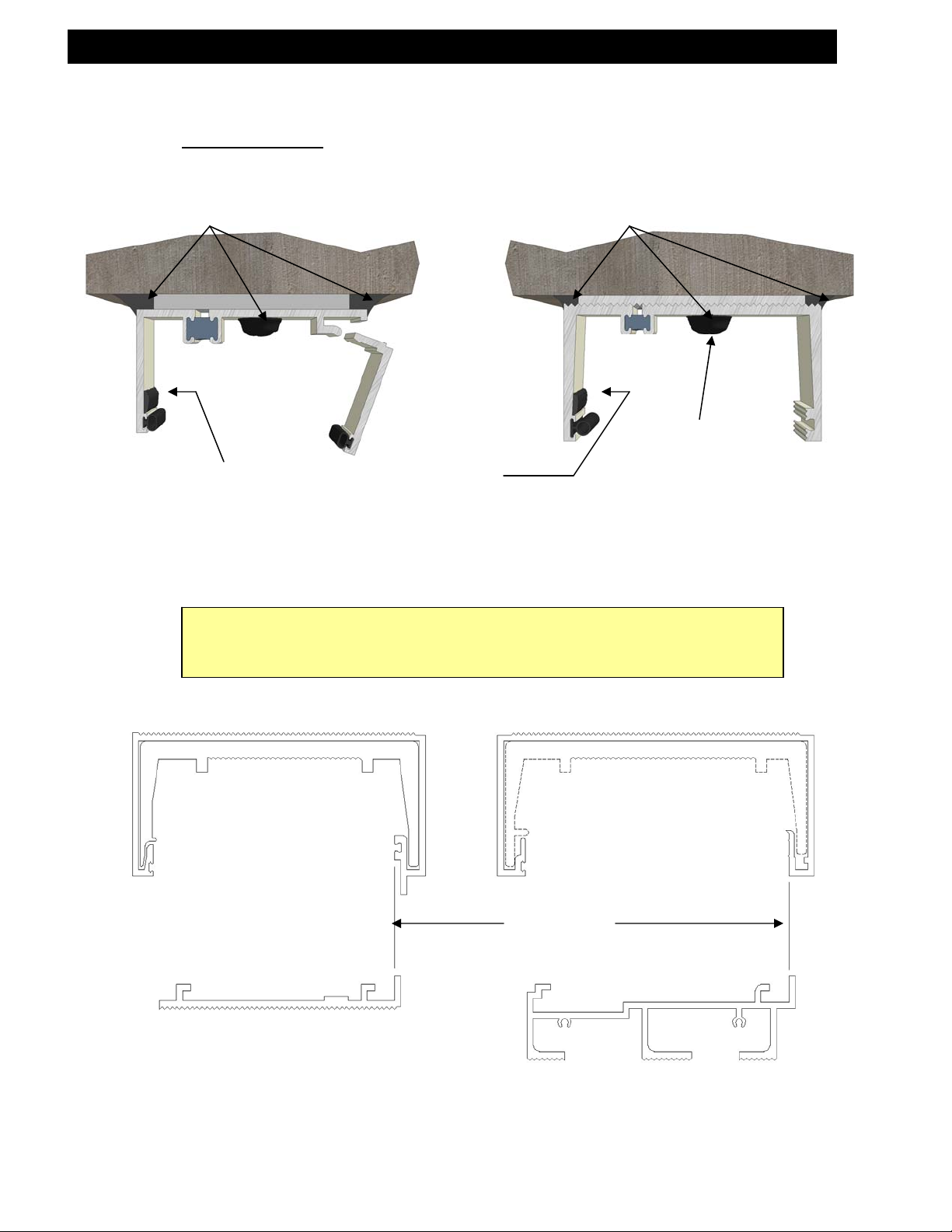
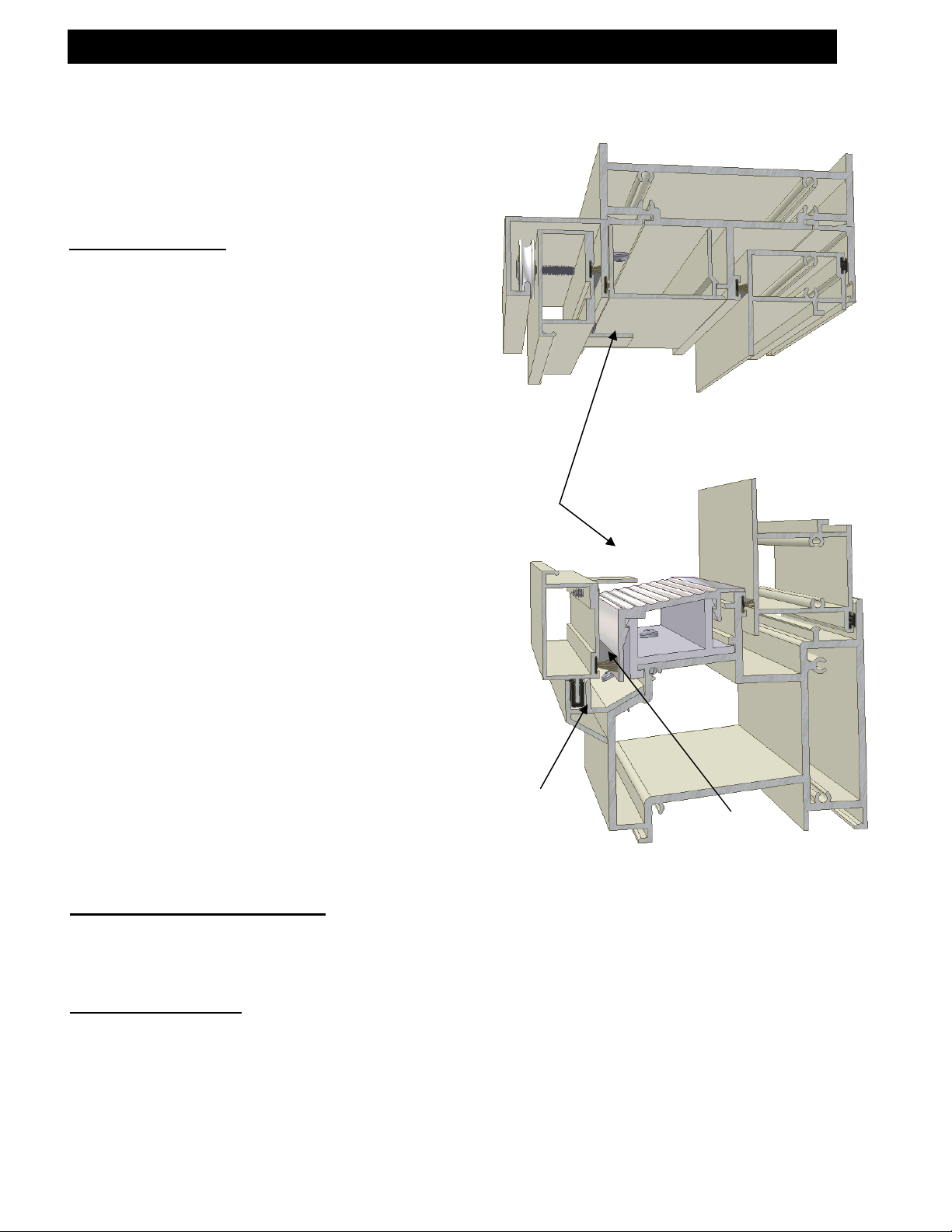
2. Seal sliding door head to the building substrate. The seal joint along the head is to marry in
with the seal joint down the jamb as shown. (Fig. G & H)
Access Hole
S-3014 Shown
S-3005 & S-3015 Similar
The S-3014, S-3015, & S-3005 require
an access hole to be drilled prior to
fastening the anchor (by the Erector).
Fig. “G”
Fig. “H”
Sealant
High Impact Shim
Blocking by
Erector
Sealant
by Erector
Sealant
Sealant
S-3001 Shown
S-2000/3000 Similar
Erector to Field
Drill for Anchors
Marry sealant at
head and jamb.
Building Substrate
EFCO CORPORATION 6/8/2012 PART NO. YW41 Page 10 of 59
Page 11
SLIDING GLASS DOOR INSTALLATION INSTRUCTIONS
3. Seal sliding door jambs to the building substrate. The seal joint along the jamb is to marry in
with the seal joint across the head.
4. Stuff access holes, fixed jamb side, with backer rod and seal over the access holes before
snapping on the cover (S-3005, S-3014 & S-3015).
Sealant
Sealant
Fig. “H”
Access Hole
S-3001 Shown
S-2000/3000 Similar
Blocking by
Erector
Erector to Field Drill
for Anchors and
Cover Anchors With
Sealant
High Impact Shim
by Erector
S-3005 Shown
S-3014 & 3015 Similar
Erector to Field
Drill for Anchors
High Impact Shim
by Erector
Sealant
Sealant
EFCO CORPORATION 6/8/2012 PART NO. YW41 Page 11 of 59
Page 12

SLIDING GLASS DOOR INSTALLATION INSTRUCTIONS
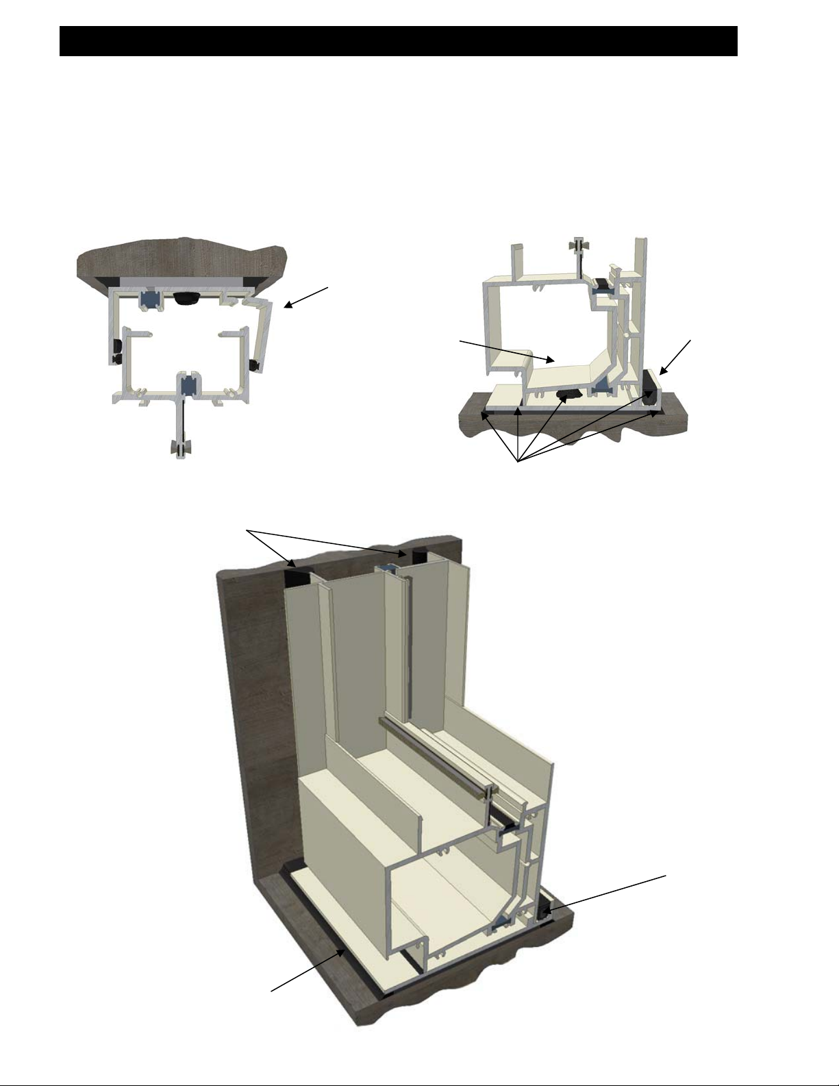
B. Installation With Subframe
All subframe material shipped long for field cut to fit and field drilling.
1. Measure the opening for the horizontal opening dimension.
2. Apply the end dams and install the subsill with erector-supplied fasteners, and apply sealant
to the head of the fasteners. Also seal the end dam to the subsill and the end dam to the
building substrate. (Fig I)
ERECTOR NOTE
that the head of the fasteners does not interfere with the door sill.
.062” aluminum angle with
chromate or anodized finish.
End dam to be placed under the
subsill before anchoring the
subsill.
: When drilling and locating the fasteners, care must be taken to ensure
Typical Starter Sill Application for
all Sliding Glass Doors Series.
Fig. “I”
Sealant
Erector to field drill
for anchors and
cover anchors with
sealant
Silicone sealant by others to be
continuous from the subsill to the end
dam. Silicone should have a minimum
contact on each surface of ½”.
Erector Note:
This sealant could interfere with end of
jambs.
Seal end dam to the subsill and end dam to the building substrate as shown.
EFCO CORPORATION 6/8/2012 PART NO. YW41 Page 12 of 59
Page 13
p
SLIDING GLASS DOOR INSTALLATION INSTRUCTIONS
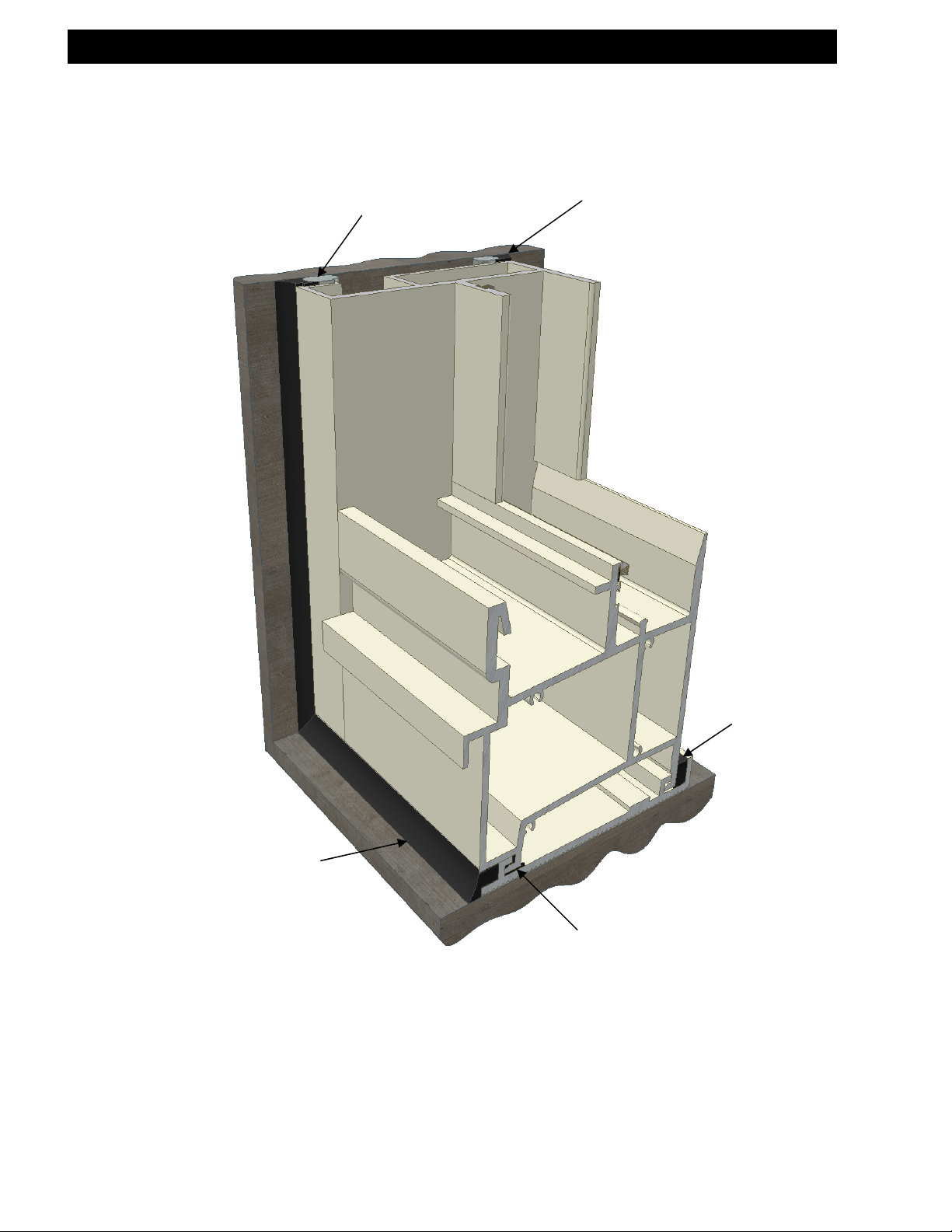
3. Subheads to be field cut to length and installed.
ERECTOR NOTE:
Sealant
Backbed the Sliding Glass Door to
subhead contact area with silicone sealant
before installing the door or cap seal after
the door is installed.
When preparing subframe for anchorage into the building opening please
make note of plumb line alignment of subhead to subsill as shown in
exam
les below.
Two-piece and one-piece subheads will seal the same. (Fig. J)
Fig. “J”
Sealant
Erector to Field
Drill for Anchors
Example for:
Series 3014, 3015, 3005
sliding glass doors and
2900, 3016, 3017 fixed
windows.
EFCO CORPORATION 6/8/2012 PART NO. YW41 Page 13 of 59
Example for:
Series 5XP sliding glass
doors and 5XF fixed windows.
Plumb Line
Page 14
r
SLIDING GLASS DOOR INSTALLATION INSTRUCTIONS
The opening is now ready to install the Sliding Glass Door frame.
(See assembly instructions for appropriate series on project)
4. Load the field assembled door frame into the anchored subframe. Snap-in the interior
subhead closure for all two-piece subhead applications. (Fig. K) Drive-in the continuous
silicone wedge between the doorframe and the interior subsill leg and cover wedge with
silicone. (Fig. L)
Compatible Silicone
Sealant by Others
Fig. “M”
S-3001 Shown
S-2000 & S-3000 Similar
Compatible Silicone
Sealant by Others
Fig. “K”
S-3001 Shown
All Other Series
are Simila
Snap-in
Closure
Erector to Field
Drill for Anchors
Fig. “L”
To ensure a
watertight seal,
silicone over the
continuous drivein wedge.
Sealant
Note:
All sealant, interior and exterior, to
marry one with another.
Sealant Over
Drive-In Dart
EFCO CORPORATION 6/8/2012 PART NO. YW41 Page 14 of 59
Page 15
SLIDING GLASS DOOR INSTALLATION INSTRUCTIONS
Silicone Sealant by
Fig. “N”
Backer Rod by
Others
Compatible
Others
Note:
All sealant, interior and exterior, to marry one with another.
Compatible
Silicone Sealant by
Others
S-3005 Shown
S-3014 & S-3015
Similar
A bead of sealant to be
applied in this cavity before
door frame is interlocked in
place.
Sealant
EFCO CORPORATION 6/8/2012 PART NO. YW41 Page 15 of 59
Page 16
SLIDING GLASS DOOR INSTALLATION INSTRUCTIONS
Compatible Silicone
Sealant by Others
Backbed or Cap Seal
Silicone Compatible
Erector Note:
Not all Sliding Door subheads will be equipped with a drive-in wedge in the interior side of the
subhead. When bulb vinyl is used, a silicone cap will not be required.
Fig. “O”
Sealant by Others
S-3014 Shown
S-3005 & S-3015 Similar
Two-Piece Subheads
Backer Rod
by Others
Similar
Silicone Compatible
Cap Seal by Others
Drive-in
Wedge
Foam Backer Rod
for non Three Sided
Adhesion
EFCO CORPORATION 6/8/2012 PART NO. YW41 Page 16 of 59
Page 17
pp
SLIDING GLASS DOOR INSTALLATION INSTRUCTIONS
These recommendations are for general erection procedures only. For actual job conditions,
see the details on the shop drawings. For perimeter anchor type and spacing, refer to the
a
roved shop drawings or consult theproject design professional.
SECTION III: Series Specific Assembly Installation
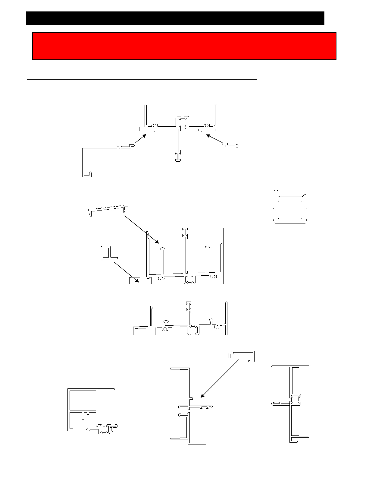
S-2000 or S-3000 Door Assembly Instructions
EFCO CORPORATION 6/8/2012 PART NO. YW41 Page 17 of 59
3492 Head
Closure
EW65 Threshold
3237 Screen
Sill Guide
3483 OXO
Meeting Rail
3247
Fixed Jamb
3491 Head
3390 Head
Closure
HV04 Sash Stop
3234 Sill (S-3000)
3320 Sill (S-2000)
3190
Closure
3236
Operable Jamb
Page 18
SLIDING GLASS DOOR INSTALLATION INSTRUCTIONS
Jamb
H017 Gasket (S-2000)
H073 Gasket (S-3000)
(adhere to the jamb)
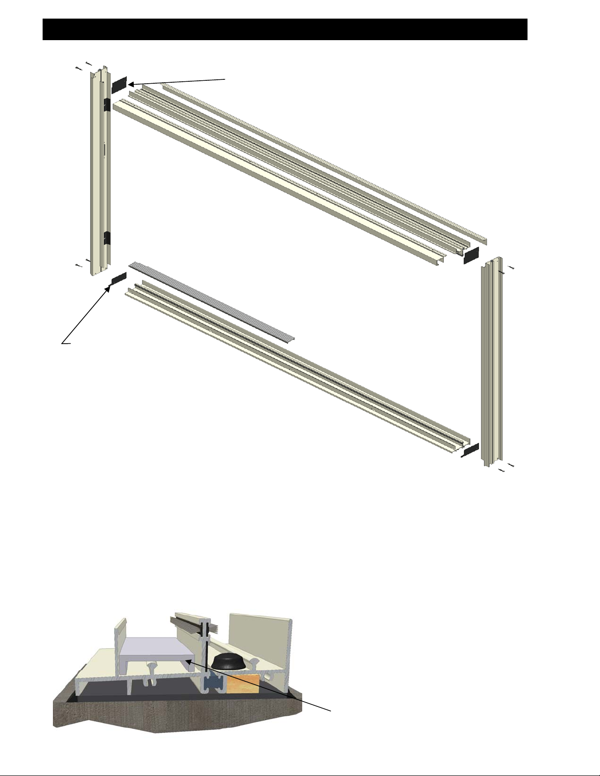
Locate 3236 and 3247 jambs. Adhere H075 head gaskets and H017 (S-2000) or H073 (S-3000) sill
gaskets to the jambs. Gaskets have pressure sensitive adhesive on one side of the gasket. Match up the
holes in the gasket with the holes in the jambs and adhere to the jamb.
Locate 3491 head and 3320 (S-2000) or 3234 (S-3000) sill. Fasten the head and the sill to the jambs with
SLQ6 screws (#8 x 1 ¼” PL-PH-SMS 410 B-LP MG).
For proper door operation, position the doorframe in the opening by using shims as needed to ensure that
the frame is plumb, square, and level without warp, twist, or bow.
3492
Exterior
H075 Gasket
(adhere to the jamb)
Interior
Head
3390
EW65
Threshold
Jamb
Sill
Lay the setting channels (F132 S-2000
or FD28 S-3000) in the outside sill
track at approximate quarter points of
the fixed panel.
Setting Channel
F132 Shown
EFCO CORPORATION 6/8/2012 PART NO. YW41 Page 18 of 59
Page 19

SLIDING GLASS DOOR INSTALLATION INSTRUCTIONS
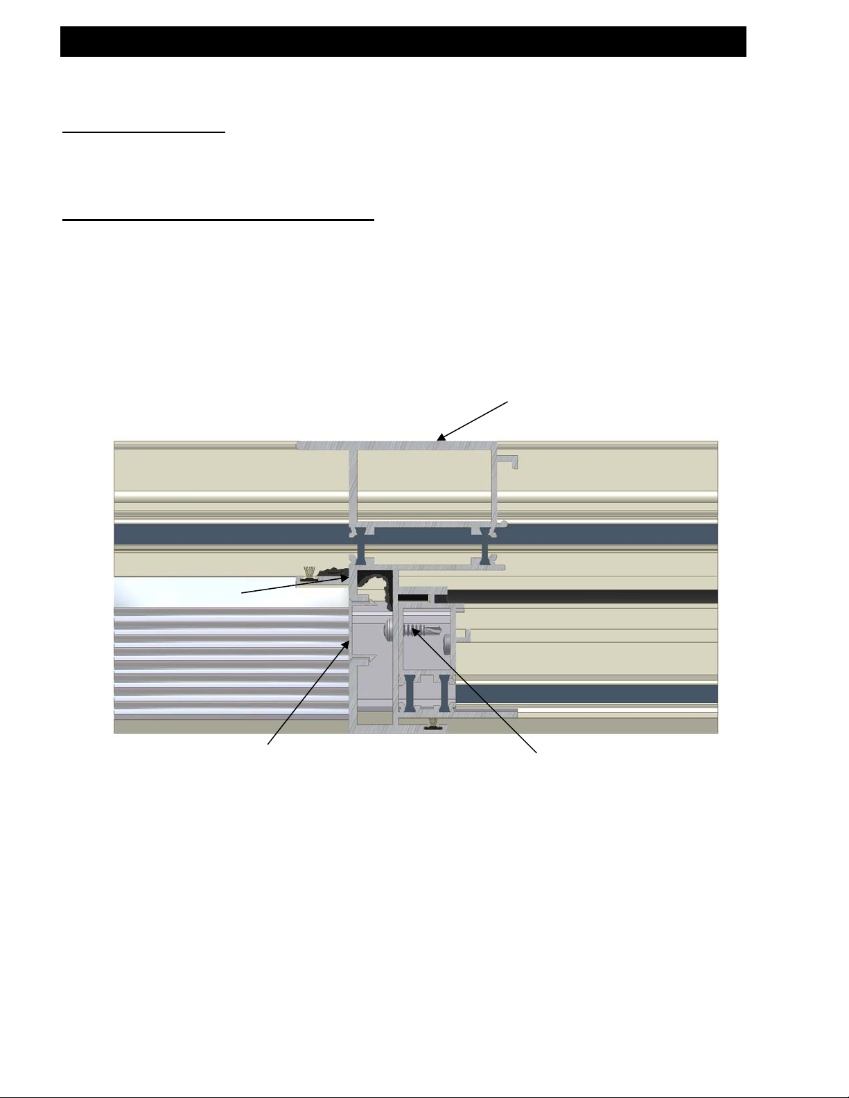
Before fixed panel is installed, verify that
HN06 blocks are in place. This allows the
interlocks not to interfere with one another
after final assembly.
Locate the fixed panel and install the fixed panel into the doorframe on the operable jamb side of the door.
Locate 3492 head closure and install into the head. Through existing holes in the head closure, fasten
STK5 tek screws (#10-16 x ¾” PL-PH 410 tek). Move the fixed panel into the fixed jamb and finish
installing the STK5 tek screws in the head.
Silicone in Place HN06
(1/8”x 1”x 4”) Setting Block
3492 Head
Closure
SFP1
STK5
Fixed Panel
Setting Channel
F132 Shown
Before installation of the
fixed panel, run a bead of
silicone, at this
intersection, on both
jambs. Do this at the
head and the sill.
HN06
EFCO CORPORATION 6/8/2012 PART NO. YW41 Page 19 of 59
Page 20

SLIDING GLASS DOOR INSTALLATION INSTRUCTIONS
STK5
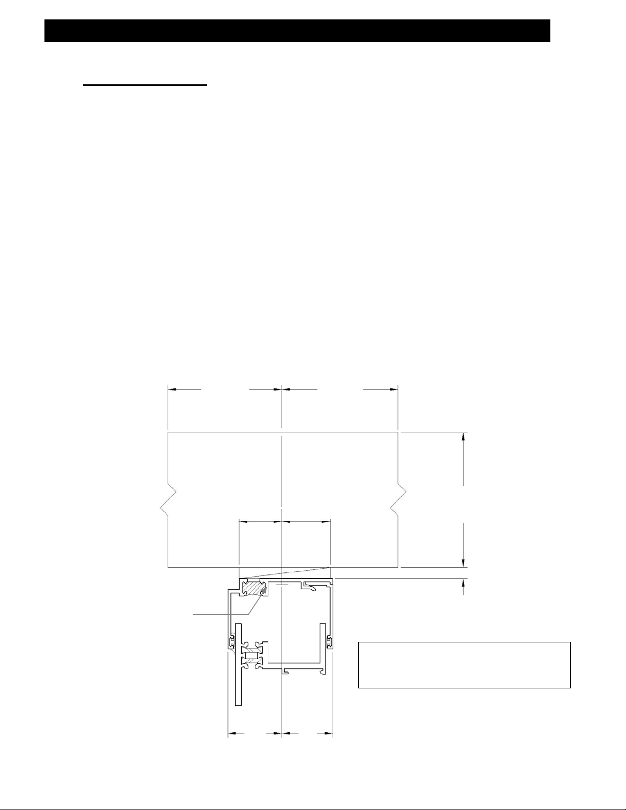
Located at the interior side of the head, where the meeting rail of the fixed panel tucks into the head, there
will be two holes. After obtaining the 2 1/16” dimension at the jamb, match drill through the two holes with
a 5/32” drill bit. Fasten SFP1 screws (#10-16 x 1” PL-FH-SMS 18-8) through the two holes. (Fig P)
Through existing holes in the jamb, attach STK5 screws (#10-16 x 3/4” PL-FH-SMS 410 tek). After the
STK5 screws are attached in the jamb, slide die #3190 cover over the fasteners.
3190
2 1/16”
HV95 3/16” spacer
siliconed in place at
quarter points
This dimension must be maintained to
Jamb Cam
ensure proper embedment of the fixed panel;
thereby, ensuring proper interlock of the
meeting rail.
Fig. “P”
Fasten SFP1 screws
after match drilling
from pre-existing
countersunk holes.
EFCO CORPORATION 6/8/2012 PART NO. YW41 Page 20 of 59
Page 21

SLIDING GLASS DOOR INSTALLATION INSTRUCTIONS
Fixed Panel
Meeting Rail
Note: To properly seal the fixed panel, the seal behind the meeting rail interlock must be
done before the operable panel is loaded into the frame. If the fixed panel seal is to be
applied at a later time, a partial seal behind the interlock pocket must be made before
loading the operable panel. This partial seal should be the width of the meeting rail sightline.
The sealant applicator can then marry the perimeter fixed panel sealant with the sealant
already applied in the interlock pocket after loading the operable panel.
Sealant
Marry the continuous silicone
seals of the fixed panel bottom
rail along the sill and the fixed
panel side rail along the jamb,
where they intersect.
Important: The seal joint shown is the
weathering seal that prevents air and
water from entering around the fixed panel.
Apply a continuous silicone seal at the fixed
panel to door frame along the parting stop at the
head, jamb, and sill. The silicone seal must
continue behind the meeting rail interlock to seal
the meeting rail to the head and sill forming a
continuous seal.
Sealant
EFCO CORPORATION 6/8/2012 PART NO. YW41 Page 21 of 59
Page 22

SLIDING GLASS DOOR INSTALLATION INSTRUCTIONS
Installing the Threshold:
notched ends is to fit into the jamb recess, and the other end is to be square cut and fitted against the fixed
panel meeting rail. Snap the threshold into the exterior track of the sill between the jamb and the fixed
meeting rail. Be sure the long lip on the threshold is towards the interior.
Locate and install the operable panel onto the sill track. Position the operable panel to one side of the
door. (See next page for OXO locking side meeting rail installation.) Locate 3390 head closure and install
up into the head. Through existing holes in the head closure, fasten STK5 tek screws (#10-16 x 3/4” PLFH-SMS 410 tek). Move the operable panel to the other side of the door and finish installing STK5 screws.
Press HV04 rubber stop into the interior track at the head. One end will butt against doorjamb.
The threshold is shipped long with a notch in both ends for field fit. One of the
Fixed Panel
Square Cut
End
Notched End
3390 Head
Closure
STK5
Operable Panel
EW65
Threshold
Screws
HV04 Sash
Stop
EFCO CORPORATION 6/8/2012 PART NO. YW41 Page 22 of 59
Page 23

SLIDING GLASS DOOR INSTALLATION INSTRUCTIONS
Hardware Adjustment:
Adjust the rollers for a plumb and equal sight line with the fixed lite panel.
Adjust the lock throw to the most extended position by turning the adjusting screw clockwise.
OXO Locking Side Fixed Panel Meeting Rail Installation:
Locate OXO fixed panel meeting rail. Install fixed panel meeting rail by setting the meeting rail on the
operable panel side of the sill. Match drill through existing holes on the meeting rail to the fixed panel
meeting rail. Fasten with SPZ4 screws (#8-15 x 1” PL-PH-SMS 18-8).
Locate 3390 head closure. The length of the closure is shipped long for field fit. Cut the length required for
one side after the meeting rail has been attached. Measure and cut the other side, installing both lengths
into the head. Through existing holes in the head closure, fasten STK5 screws (#10-16 x 3/4” PL-FH-SMS
410 tek). Move the operable panel to the other side of the door and finish installing STK5 screws.
Install threshold in the exterior track of the sill between the two fixed meeting rails. Place notched end of
the threshold toward the locking fixed meeting rail. The other end should be square cut for a tight fit.
(Does not pertain to OX, XO, or OXXO doors):
SPZ4
3483 Fixed Panel
Meeting Rail
3241 Fixed Panel
Meeting Rail
Set on top of Sill
EFCO CORPORATION 6/8/2012 PART NO. YW41 Page 23 of 59
Page 24

SLIDING GLASS DOOR INSTALLATION INSTRUCTIONS
Screen Installation:
With the screen slightly tilted outward, roll to the operable panel side of the door. Locate 3237 screen sill
guide and position guide as shown. Fasten with STC7 screws (#6-18 x 3/8” PL-FH-SMS 18-8) after match
drilling through existing holes in the sill guide with a 7/64” drill bit. Attach KS45 screen stops, into the
existing holes, located at the screen head rail and the screen sill rail.
OX, XO or OXO Configurations:
To position HK06 screen keeper, position the keeper next to the screen lock and engage the lock into the
keeper. Shut screen until the keeper hits the jamb. Match drill a 9/64” drill bit through the keeper holes.
Fasten the keeper to the jamb with SFP6 screws (#8-15 x 1/2” PL-TH-SMS 18-8).
OXXO Configuration:
To position HK08 screen keeper, position the keeper next to the screen lock and engage the lock into the
keeper. Close both screens together. Match drill a 9/64” drill bit through the keeper holes. Fasten the
keeper to the screen astragal with SFP6 screws (#8-15 x ½” PL-TH-SMS 18-8).
3237 Screen
Sill Guide
Locate the screen. Guide the screen rollers through the notches located in the head.
Screen Stops
EFCO CORPORATION 6/8/2012 PART NO. YW41 Page 24 of 59
Page 25

ppr
SLIDING GLASS DOOR INSTALLATION INSTRUCTIONS
These recommendations are for general erection procedures only. For actual job conditions,
see the details on the shop drawings. For perimeter anchor type and spacing, refer to the
a
oved shop drawings or consult the project design professional.
S-3001 Door Assembly Instructions
S-3000 Modified Door Assembly Instructions
3492 Head
Closure
3237 Screen
Sill Guide
3484 OXO
Meeting Rail
EW65 Threshold
HV04 Sash Stop
S-3001
1J57 Sill
3246
Operable Jamb
3490 Head
3390 Head
Closure
3190
Closure
3491
S-3000 Modified (10#)
S-3000 Modified (10#)
1J55 Sill
3188
Fixed Jamb
EFCO CORPORATION 6/8/2012 PART NO. YW41 Page 25 of 59
Page 26

(
)
SLIDING GLASS DOOR INSTALLATION INSTRUCTIONS
H098 Gasket (S-3000 Modified)
Locate 3246 and 3188 jambs.
Adhere H076 head gaskets and H031 sill gaskets to the jambs (S-3001).
Adhere H075 head gaskets and H098 sill gaskets to the jambs (S-3000 modified).
Gaskets have a pressure sensitive adhesive on one side of the gasket. Match up the holes in the gasket
with the holes in the jambs and adhere to the jamb.
Locate the head and sill. Fasten the head and sill to the jambs with SLQ6 screws (#8 x 1 ¼” PL-PH-SMS
410 B-LP MG).
For proper door operation, position the doorframe in the opening by using shims as needed to ensure that
the frame is plumb, square, and level without warp, twist, or bow.
Jamb
3492
H031 Gasket (S-3001)
(adhere to the jamb)
Exterior
H076 Gasket (S-3001)
H075 Gasket (S-3000 Modified)
adhere to the jamb
Head
EW65
Threshold
Sill
Lay the setting channels F132 in the
outside sill track at approximate quarter
points of the fixed panel.
Setting Channel
F132
Interior
3390
Jamb
EFCO CORPORATION 6/8/2012 PART NO. YW41 Page 26 of 59
Page 27

SLIDING GLASS DOOR INSTALLATION INSTRUCTIONS
Before fixed panel is installed, verify that
HN06 blocks are in place. This allows the
interlocks not to interfere with one another
after final assembly.
Locate the fixed panel and install the fixed panel into the doorframe on the operable jamb side of the door.
Locate 3492 head closure and install into the head. Through existing holes in the head closure, fasten
STK5 tek screws (#10-16 x ¾” PL-PH 410 tek). Move the fixed panel into the fixed jamb and finish
installing the STK5 tek screws in the head.
3492 Head
Closure
Setting Channel
Silicone in Place HN06
(1/8”x 1”x 4”) Setting Block
STK5
F132
Fixed Panel
HN06
SFP1
Before installation of the
fixed panel, run a bead of
silicone at this
intersection, on both
jambs. Do this at the
head and sill.
EFCO CORPORATION 6/8/2012 PART NO. YW41 Page 27 of 59
Page 28

SLIDING GLASS DOOR INSTALLATION INSTRUCTIONS
STK5
Located at the interior side of the head, where the meeting rail of the fixed panel tucks into the head, there
will be two holes. After obtaining the 2 1/16” dimension at the jamb, match drill through the two holes with
a 5/32” drill bit. Fasten SFP1 screws (#10-16 x 1” PL-FH-SMS 18-8) through the two holes. (Fig Q)
Through existing holes in the jamb, attach STK5 screws (#10-16 x 3/4” PL-FH-SMS 410 tek). After the
STK5 screws are attached in the jamb, slide die #3190 cover over the fasteners.
2 1/16”
3190
HV95 3/16” spacer
siliconed in place at
quarter points.
This dimension must be obtained to ensure
Jamb Cam
proper embedment of the fixed panel;
thereby, ensuring proper interlock of the
meeting rail.
Fig. “Q”
Fasten SFP1 screws
after match drilling
from pre-existing
countersunk holes.
EFCO CORPORATION 6/8/2012 PART NO. YW41 Page 28 of 59
Page 29

SLIDING GLASS DOOR INSTALLATION INSTRUCTIONS
Fixed Panel
Meeting Rail
Note: To properly seal the fixed panel, the seal behind the meeting rail interlock must be
done before the operable panel is loaded into the frame. If the fixed panel seal is to be
applied at a later time, a partial seal behind the interlock pocket must be made before
loading the operable panel. This partial seal should be the width of the meeting rail sightline.
The sealant applicator can then marry the perimeter fixed panel sealant with the sealant
already applied in the interlock pocket after loading the operable panel.
Sealant
Sealant
IMPORTANT: The seal joint shown is the
weathering seal that prevents air and
water from entering around the fixed panel.
Apply a continuous silicone seal at the fixed
panel to door frame along the parting stop at the
head, jamb, and sill. The silicone seal must
continue behind the meeting rail interlock to seal
the meeting rail to the head and sill forming a
continuous seal.
Marry the continuous silicone
seals of the fixed panel bottom
rail along the sill and the fixed
panel side rail along the jamb,
where they intersect.
EFCO CORPORATION 6/8/2012 PART NO. YW41 Page 29 of 59
Page 30

SLIDING GLASS DOOR INSTALLATION INSTRUCTIONS
Installing the Threshold:
notched ends is to fit into the jamb recess, and the other end is to be square cut and fitted against the fixed
panel meeting rail. Snap the threshold into the exterior track of the sill between the jamb and the fixed
meeting rail. Be sure the long lip on the threshold is towards the interior.
Locate and install the operable panel onto the sill track. Position the operable panel to one side of the
door. (See next page for OXO locking side meeting rail installation.) Locate 3390 head closure and install
up into the head. Through existing holes in the head closure, fasten STK5 tek screws (#10-16 x 3/4” PLPH-SMS 410 tek). Move the operable panel to the other side of the door and finish installing STK5 screws.
Press HV04 rubber stop into the interior track at the head. One end will butt against doorjamb.
Fixed Panel
The threshold is shipped long with a notch in both ends for field fit. One of the
Notched End
Square
Cut End
3390 Head
Closure
STK5 Screws
Operable Panel
EW65
Threshold
HV04
Sash Stop
EFCO CORPORATION 6/8/2012 PART NO. YW41 Page 30 of 59
Page 31

SLIDING GLASS DOOR INSTALLATION INSTRUCTIONS
Hardware Adjustment:
Adjust the rollers for a plumb and equal sight line with the fixed lite panel.
Adjust the lock throw to the most extended position by turning the adjusting screw clockwise.
OXO Locking Side Fixed Panel Installation:
OXO fixed panel, meeting rail. Install fixed panel meeting rail by setting the meeting rail on the operable
panel side of the Sill. Match drill through existing holes on the meeting rail to the fixed panel meeting rail.
Fasten with SPZ4 screws (#8-15 x 1” PL-FH-SMS 18-8).
Locate 3390 head closure. The length of the closure is shipped long for field fit. Cut the length required for
one side after the meeting rail has been attached. Measure and cut the other side, installing both lengths
into the head. Through existing holes in the head closure, fasten STK5 screws (#10-16 x 3/4” PL-FH-SMS
410 tek). Move the operable panel to the other side of the door and finish installing STK5 screws.
Install threshold in the exterior track of the sill between the two fixed meeting rails. Place notched end of
the threshold toward the locking fixed meeting rail. The other end should be square cut for a tight fit.
Set on top of Sill
(Does not pertain to OX, XO, or OXXO Doors): Locate
3484 Fixed Panel
Meeting Rail
SPZ4
3241 Fixed Panel
Meeting Rail
EFCO CORPORATION 6/8/2012 PART NO. YW41 Page 31 of 59
Page 32

SLIDING GLASS DOOR INSTALLATION INSTRUCTIONS
Screen Installation:
With the screen slightly tilted outward, roll to the operable panel side of the door. Locate 3237 screen sill
guide and position guide as shown. Fasten with STC7 (#6-18 x 3/8” PL-FH-SMS 18-8) after match drilling
through existing holes in the sill guide with a 7/64” drill bit.
Locate the screen. Guide the screen rollers through the notches located in the head.
Attach KS45 screen stops, into the existing
holes, located at the screen head rail and the screen sill rail.
OX, XO or OXO Configurations:
To position HK06 screen keeper, position the keeper next to the screen lock and engage the lock into the
keeper. Shut screen until the keeper hits the jamb. Match drill a 9/64” drill bit through the keeper holes.
Fasten the keeper to the jamb with SFP6 screws (#8-15 x 1/2” PL-TH-SMS 18-8).
OXXO Configuration:
To position HK08 screen keeper, position the keeper next to the screen lock and engage the lock into the
keeper. Close both screens together. Match drill a 9/64” drill bit through the keeper holes. Fasten the
keeper to the screen astragal with SFP6 screws (#8-15 x ½” PL-TH-SMS 18-8).
3237 Screen
Sill Guide
Screen Stops
EFCO CORPORATION 6/8/2012 PART NO. YW41 Page 32 of 59
Page 33

pp
SLIDING GLASS DOOR INSTALLATION INSTRUCTIONS
These recommendations are for general erection procedures only. For actual job conditions,
see the details on the shop drawings. For perimeter anchor type and spacing, refer to the
a
roved shop drawings or consult the project design professional.
S-3015 Door Assembly Instructions
3151 Head
Closure
3167 Screen
Sill Guide
3179 Threshold
11F9 Head
Filler
1J90 OXO
Meeting Rail
1283
Closure
1J89 Head
1J92 Sill
1J05
Operable Jamb
3150 Head
Closure
HV05 Sash Stop
1J91
Fixed Jamb
3499
Closure
EFCO CORPORATION 6/8/2012 PART NO. YW41 Page 33 of 59
Page 34

SLIDING GLASS DOOR INSTALLATION INSTRUCTIONS
Jamb
Locate 1J05 and 1J91 jambs.
Adhere H068 head gaskets and H069 sill gaskets to the jambs.
Gaskets have a pressure sensitive adhesive on one side of the gasket. Match up the holes in the gasket
with the holes in the jambs and adhere to the jamb.
Locate the head and sill. Fasten the head and sill to the jambs with SLQ9 screws (#10 x 1 ¼” PL-PH-SMS
410 B-LP MG).
Anchor the doorframe into the opening.
For proper door operation, position the doorframe in the opening by using shims as needed to ensure that
the frame is plumb, square, and level without warp, twist, or bow.
H069 Gasket
(Adhere to Jamb)
Exterior
3151
H068 Gasket
(Adhere to Jamb)
Head
3179
Threshold
Interior
3150
Jamb Sill
EFCO CORPORATION 6/8/2012 PART NO. YW41 Page 34 of 59
Page 35

SLIDING GLASS DOOR INSTALLATION INSTRUCTIONS
Locate the fixed panel and install the fixed panel
into the doorframe on the operable jamb side of
the door. Locate 3151 head closure and install
into the head. Through existing holes in the
head closure, fasten STK5 tek screws (#10-16 x
¾” PL-PH 410 tek). Move the fixed panel into
the fixed jamb and finish installing the STK5 tek
screws in the head.
There will be two countersunk holes located at
the interior side of the head, where the meeting
rail of the fixed panel tucks into the head. After
obtaining the 1 1/16” dimension (shown on the
following page) at the jamb, match drill through
the two countersunk holes with a 5/32” drill bit.
Fasten SFP1 screws (#10-15 x 1” PL-FH-SMS
18-8) through the two countersunk holes.
3151 Head
Closure
Before installation of the fixed panel, run
a bead of silicone at this intersection, on
both jambs. Do this at the head and sill.
SFP1
STK5
Fixed Panel
EFCO CORPORATION 6/8/2012 PART NO. YW41 Page 35 of 59
Page 36

SLIDING GLASS DOOR INSTALLATION INSTRUCTIONS
1 1/16”
Once the fixed panel is
installed, seal the meeting rail
to the frame, at this location.
Do this at the head and sill.
Locate 3499 jamb cover and snap-in place after
anchoring the jamb. (This can be done at anytime after
the door jambs are anchored.)
The 1 1/16” dimension must be obtained to ensure
proper embedment of the fixed panel; thereby, ensuring
proper interlock of the meeting rail.
EFCO CORPORATION 6/8/2012 PART NO. YW41 Page 36 of 59
Page 37

SLIDING GLASS DOOR INSTALLATION INSTRUCTIONS
Fixed Panel
Meeting Rail
Note: To properly seal the fixed panel, the seal behind the meeting rail interlock must be
done before the operable panel is loaded into the frame. If the fixed panel seal is to be
applied at a later time, a partial seal behind the interlock pocket must be made before
loading the operable panel. This partial seal should be the width of the meeting rail sightline.
The sealant applicator can then marry the perimeter fixed panel sealant with the sealant
already applied in the interlock pocket after loading the operable panel.
Marry the continuous
silicone seals of the fixed
panel bottom rail along the
sill and the fixed panel side
rail along the jamb where
they intersect.
Sealant
IMPORTANT: The seal joint shown is the
weathering seal that prevents air and
water from entering around the fixed panel.
Apply a continuous silicone seal at the fixed
panel to door frame along the parting stop at the
head, jamb, and sill. The silicone seal must
continue behind the meeting rail interlock to seal
the meeting rail to the head and sill forming a
continuous seal.
Sealant
EFCO CORPORATION 6/8/2012 PART NO. YW41 Page 37 of 59
Page 38

SLIDING GLASS DOOR INSTALLATION INSTRUCTIONS
Installing the Threshold:
notched ends is to fit into the jamb recess, and the other end is to be square cut and fitted against the fixed
panel meeting rail. Locate 3179 threshold. Cut to length between the jamb and the meeting rail. Push
down over the clips that are fastened to the sill.
Fixed panel should be sealed in doorframe before loading the operable panel and attaching head filler and
threshold.
Locate 11F9 head filler. Cut to length between the jamb and meeting rail. Push into the exterior track, at
the head.
Locate and install the operable panel onto the sill track. Position the operable panel to one side of the
door. Locate 3150 head closure and install up into the head. Through existing holes in the head closure,
fasten STK5 tek screws (#10-16 x 3/4” PL-PH-SMS 410 tek). Move the operable panel to the other side of
the door and finish installing STK5 screws in the head.
Notched End
The threshold is shipped long with a notch in both ends for field fit. One of the
Fixed Panel
3179
Threshold
Square Cut
End
EFCO CORPORATION 6/8/2012 PART NO. YW41 Page 38 of 59
Page 39

SLIDING GLASS DOOR INSTALLATION INSTRUCTIONS
Locate HV05 operable panel stop and push up into the head, next to the fixed jamb.
Filler
Operable Panel
3179
Threshold
3150 Head
Closure
STK5 Screws 11F9 Head
HV05 Sash
Stop
EFCO CORPORATION 6/8/2012 PART NO. YW41 Page 39 of 59
Page 40
SLIDING GLASS DOOR INSTALLATION INSTRUCTIONS
Hardware Adjustment:
Adjust the rollers for a plumb and equal sight line with the fixed lite panel.
OXO Locking Side Fixed Panel Installation:
Locate OXO meeting rail. This rail will be attached to the fixed panel by match drilling through existing
holes on the meeting rail to the fixed panel meeting rail. Fasten with STS0 screws (#12-14 x 3/4” PL-FHSMS 410 tek).
Install threshold in the exterior track of the sill between the two fixed meeting rails.
Pump sealant in the area shown at the head and sill. The sealant needs to cover the joint where the
vertical intersects with the head and sill. Tool sealant with a flat object. After sealant has been tooled,
snap 1283 closure into place.
1283 Closure
(Does not pertain to OX, XO, or OXXO doors):
1J90 Fixed Panel
Meeting Rail
Sealant
STS0
EFCO CORPORATION 6/8/2012 PART NO. YW41 Page 40 of 59
Page 41

SLIDING GLASS DOOR INSTALLATION INSTRUCTIONS
Screen Installation:
Locate the screen. Guide the screen rollers,
which are located at the head, through the
notches in the 3151 head closure. Roll the
screen to the operable panel side.
Locate the 3167 screen sill guide. Position guide
as shown. Match drill through existing holes in
the 3167 screen guide with a 9/64” drill bit.
Fasten the screen sill guide with SPZ1 screws
(#8-15 x ¾” PL-PH-SMS 18-8).
Attach KS45 screen stops, into the existing holes,
located at the screen head rail and the screen sill
rail.
OX, XO or OXO Configurations:
To position HK06 screen keeper, position the keeper next to the screen lock and engage the lock into the
keeper. Shut screen until the keeper hits the jamb. Match drill a 9/64” drill bit through the keeper holes.
Fasten the keeper to the jamb with SFP6 screws (#8-15 x 1/2” PL-TH-SMS 18-8).
OXXO Configuration:
To position HK08 screen keeper, position the keeper next to the screen lock and engage the lock into the
keeper. Close both screens together. Match drill a 9/64” drill bit through the keeper holes. Fasten the
keeper to the screen astragal with SFP6 screws (#8-15 x ½” PL-TH-SMS 18-8).
KS45
Screen Stop
3167 Screen
Sill Guide
EFCO CORPORATION 6/8/2012 PART NO. YW41 Page 41 of 59
Page 42

pp
SLIDING GLASS DOOR INSTALLATION INSTRUCTIONS
These recommendations are for general erection procedures only. For actual job conditions,
see the details on the shop drawings. For perimeter anchor type and spacing, refer to the
a
roved shop drawings or consult the project design professional.
S-3014 Door Assembly Instructions
3151 Head
Closure
3937
Closure
3167 Screen
Sill Guide
3179 Threshold
11G4 OXO
Meeting Rail
11F9 Head
Filler
3203
Operable Jamb
11G0 Head
3150 Head
Closure
11G1 Sill
HV05 Sash Stop
11G3
Fixed Jamb
3499
Closure
EFCO CORPORATION 6/8/2012 PART NO. YW41 Page 42 of 59
Page 43

SLIDING GLASS DOOR INSTALLATION INSTRUCTIONS
Jamb
Locate 3203 and 11G3 jambs.
Adhere H068 head gaskets and H069 sill gaskets to the jambs.
Gaskets have a pressure sensitive adhesive on one side of the gasket. Match up the holes in the gasket
with the holes in the jambs and adhere to the jamb.
Locate the head and sill. Fasten the head and sill to the jambs with SLQ9 screws (#10 x 1 ¼” PL-PH-SMS
410 B-LP MG).
Anchor the doorframe into the opening.
For proper door operation, position the doorframe in the opening by using shims as needed to ensure that
the frame is plumb, square, and level without warp, twist, or bow.
H069 Gasket
(Adhere to Jamb)
3151
Exterior
H068 Gasket
(Adhere to Jamb)
Sill
Interior
Head
3150
3179
Threshold
Jamb
EFCO CORPORATION 6/8/2012 PART NO. YW41 Page 43 of 59
Page 44

SLIDING GLASS DOOR INSTALLATION INSTRUCTIONS
Locate the fixed panel and install the fixed panel
into the doorframe on the operable jamb side of
the door. Locate 3151 head closure and install
into the head. Through existing holes in the
head closure, fasten STK5 tek screws (#10-16 x
¾” PL-PH 410 tek). Move the fixed panel into
the fixed jamb and finish installing the STK5 tek
screws in the head.
There will be two countersunk holes located at
the interior side of the head, where the meeting
rail of the fixed panel tucks into the head. After
obtaining the 1 1/16” dimension (shown on the
following page) at the jamb, match drill through
the two countersunk holes with a 5/32” drill bit.
Fasten SFP1 screws (#10-15 x 1” PL-FH-SMS
18-8) through the two countersunk holes.
Before installation of the fixed panel, run
a bead of silicone, at this intersection, on
both jambs. Do this at the head and the
sill.
3151 Head
Closure
SFP1
STK5
Fixed Panel
EFCO CORPORATION 6/8/2012 PART NO. YW41 Page 44 of 59
Page 45

SLIDING GLASS DOOR INSTALLATION INSTRUCTIONS
1 1/16”
Locate 3499 jamb cover and snap-in place after
anchoring the jamb. (This can be done at anytime after
the door jambs are anchored.)
The 1 1/16” dimension must be obtained to ensure
proper embedment of the fixed panel; thereby, ensuring
proper interlock of the meeting rail.
Once the fixed panel is
installed, seal the meeting rail
to the frame, at this location.
Do this at the head and sill.
EFCO CORPORATION 6/8/2012 PART NO. YW41 Page 45 of 59
Page 46

g
SLIDING GLASS DOOR INSTALLATION INSTRUCTIONS
IMPORTANT: The seal joint shown is the
weathering seal that prevents air and
water from entering around the fixed panel.
Apply a continuous silicone seal
at the fixed panel to door frame
along the parting stop at the
head, jamb, and sill. The silicone
seal must
meeting rail interlock to seal the
meeting rail to the head and sill
formin
Sealant
EFCO CORPORATION 6/8/2012 PART NO. YW41 Page 46 of 59
continue behind the
a continuous seal.
Note: To properly seal the fixed panel, the seal behind the meeting rail interlock must be
done before the operable panel is loaded into the frame. If the fixed panel seal is to be
applied at a later time, a partial seal behind the interlock pocket must be made before
loading the operable panel. This partial seal should be the width of the meeting rail sightline.
The sealant applicator can then marry the perimeter fixed panel sealant with the sealant
already applied in the interlock pocket after loading the operable panel.
Sealant
Fixed Panel
Meeting Rail
Marry the continuous
silicone seals of the fixed
panel bottom rail along the
sill and the fixed panel side
rail along the jamb, where
they intersect.
Page 47

SLIDING GLASS DOOR INSTALLATION INSTRUCTIONS
Installing the Threshold:
notched ends is to fit into the jamb recess, and the other end is to be square cut and fitted against the fixed
panel meeting rail. Locate 3179 threshold. Cut to length between the jamb and the meeting rail. Push
down over the clips that are fastened to the sill.
Square Cut
End
Fixed panel should be sealed in doorframe before loading the operable panel and attaching head filler and
threshold.
Locate 11F9 head filler. Cut to length between the jamb and meeting rail. Push into the exterior track at
the head.
Locate and install the operable panel onto the sill track. Position the operable panel to one side of the
door. Locate 3150 head closure and install up into the head. Through existing holes in the head closure,
fasten STK5 tek screws (#10-16 x 3/4” PL-PH-SMS 410 tek). Move the operable panel to the other side of
the door and finish installing STK5 screws in the head.
The threshold is shipped long with a notch in both ends for field fit. One of the
Fixed Panel
3179
Threshold
Notched End
EFCO CORPORATION 6/8/2012 PART NO. YW41 Page 47 of 59
Page 48

SLIDING GLASS DOOR INSTALLATION INSTRUCTIONS
11F9 Head
Filler
3179
Threshold
Locate HV05 operable
panel stop and push up
into the head, next to the
fixed jamb.
STK5
Screws
Operable Panel
3150 Head
Closure
HV05 Sash
Stop
EFCO CORPORATION 6/8/2012 PART NO. YW41 Page 48 of 59
Page 49

SLIDING GLASS DOOR INSTALLATION INSTRUCTIONS
Hardware Adjustment:
Adjust the rollers for a plumb and equal sight line with the fixed lite panel.
OXO Locking Side Fixed Panel Meeting Rail Installation:
Locate OXO meeting rail. This rail will be attached to the fixed panel by match drilling through existing
holes in the meeting rail to the fixed panel meeting rail. Fasten with STS0 screws (#12-14 x 3/4” PL-PHSMS 410 tek).
Install threshold in the exterior track of the sill between the two fixed meeting rails.
Pump sealant in the area shown at the head and sill. The sealant needs to cover the joint where the
vertical intersects with the head and sill. Tool sealant with a flat object. After sealant has been tooled,
snap 3937 closure into place.
STS0
(Does not pertain to OX, XO, or OXXO doors):
11G4 Fixed Panel
Meeting Rail
Sealant
3937 Closure
EFCO CORPORATION 6/8/2012 PART NO. YW41 Page 49 of 59
Page 50
SLIDING GLASS DOOR INSTALLATION INSTRUCTIONS
Screen Installation:
Locate the screen. Guide the screen rollers,
which are located at the head, through the
notches in the 3151 head closure. Roll the
screen to the operable panel side.
Locate the 3167 screen sill guide. Position guide
as shown. Match drill through existing holes in
the 3167 screen guide with a 9/64” drill bit.
Fasten the screen sill guide with SPZ1 screws
(#8-15 x ¾” PL-PH-SMS 18-8).
Attach KS45 screen stops, into the existing holes,
located at the screen head rail and the screen sill
rail.
OX, XO or OXO Configurations:
To position HK06 screen keeper, position the keeper next to the screen lock and engage the lock into the
keeper. Shut screen until the keeper hits the jamb. Match drill a 9/64” drill bit through the keeper holes.
Fasten the keeper to the jamb with SFP6 screws (#8-15 x 1/2” PL-TH-SMS 18-8).
OXXO Configuration:
To position HK08 screen keeper, position the keeper next to the screen lock and engage the lock into the
keeper. Close both screens together. Match drill a 9/64” drill bit through the keeper holes. Fasten the
keeper to the screen astragal with SFP6 screws (#8-15 x ½” PL-TH-SMS 18-8).
KS45
Screen Stop
3167 Screen
Sill Guide
SPZ1
Fastener
EFCO CORPORATION 6/8/2012 PART NO. YW41 Page 50 of 59
Page 51

pp
SLIDING GLASS DOOR INSTALLATION INSTRUCTIONS
These recommendations are for general erection procedures only. For actual job conditions,
see the details on the shop drawings. For perimeter anchor type and spacing, refer to the
a
roved shop drawings or consult the project design professional.
S-3005 Door Assembly Instructions
3933 Head
Closure
3887 Threshold
Meeting Rail
HEP4 Setting
Chair
3936 OXO
3197
Operable Jamb
3937
Closure
3089 Head
3880 Head
Closure
HV02 or HV03
Sash Stop
4725 Sill
3499
Jamb Cover
3498
Fixed Jamb
EFCO CORPORATION 6/8/2012 PART NO. YW41 Page 51 of 59
Page 52

SLIDING GLASS DOOR INSTALLATION INSTRUCTIONS
Jamb
H063 Gasket
(Adhere to Jamb)
Locate 3197 and 3498 jambs.
Adhere H064 head gaskets and H063 sill gaskets to the jambs.
Gaskets have a pressure sensitive adhesive on one side of the gasket. Match up the holes in the gasket
with the holes in the jambs and adhere to the jamb.
Locate the head and sill. Fasten the head and sill to the jambs with SLQ7 screws (#10-16 x 1 ¼” HW SMS
410 B-LP MG).
Anchor the doorframe into the opening.
For proper door operation, position the doorframe in the opening by using shims as needed to ensure that
the frame is plumb, square, and level without warp, twist, or bow.
3933
Exterior
H064 Gasket
(Adhere to Jamb)
Head
3887
Threshold
Interior
3880
Jamb Sill
EFCO CORPORATION 6/8/2012 PART NO. YW41 Page 52 of 59
Page 53

SLIDING GLASS DOOR INSTALLATION INSTRUCTIONS
Locate HEP4 setting chairs. The setting chairs will
be quarter pointed the width of the fixed panel. Set
the setting chairs in silicone to prevent movement
when installing the fixed panel.
Locate the fixed panel and install the fixed panel
into the doorframe on the operable jamb side of the
door. Locate 3933 head closure and install into the
head. Through existing holes in the head closure,
fasten STK5 tek screws (#10-16 x ¾” PL-PH 410
tek). Move the fixed panel into the fixed jamb and
finish installing the STK5 tek screws in the head.
There will be two countersunk holes located at the
interior side of the head, where the meeting rail of
the fixed panel tucks into the head. After obtaining
the 13/16” dimension (shown on the following page)
at the jamb, match drill through the two countersunk
holes with a 5/32” drill bit. Fasten SFP1 screws
(#10-15 x 1” PL-FH-SMS 18-8) through the two
countersunk holes.
3933 Head
Closure
Before installation of the fixed panel, run
a bead of silicone at this intersection, on
both jambs. Do this at the head and sill.
STK5
Fixed Panel
SFP1
HEP4
EFCO CORPORATION 6/8/2012 PART NO. YW41 Page 53 of 59
Page 54

SLIDING GLASS DOOR INSTALLATION INSTRUCTIONS
13/16”
Locate 3499 jamb cover and snap-in place after
anchoring the jamb. (This can be done at anytime
after the door jambs are anchored.)
The 13/16” dimension must be maintained to ensure
proper embedment of the fixed panel; thereby,
ensuring proper interlock of the meeting rail.
Once the fixed panel is
installed, seal the meeting rail
to the frame, at this location.
Do this at the head and sill.
EFCO CORPORATION 6/8/2012 PART NO. YW41 Page 54 of 59
Page 55

SLIDING GLASS DOOR INSTALLATION INSTRUCTIONS
Locate W113 shims and drive the shims along the fixed panel sill. Seal around the fixed panel head, sill,
and jamb at the interior side of the door.
Sealant
Note: To properly seal the fixed panel, the seal behind the meeting rail interlock must be
done before the operable panel is loaded into the frame. If the fixed panel seal is to be
applied at a later time, a partial seal behind the interlock pocket must be made before
loading the operable panel. This partial seal should be the width of the meeting rail sightline.
The sealant applicator can then marry the perimeter fixed panel sealant with the sealant
already applied in the interlock pocket after loading the operable panel.
Marry the continuous
silicone seals of the
fixed panel bottom rail
along the sill and the
fixed panel side rail
along the jamb, where
they intersect.
Fixed Panel
Meeting Rail
IMPORTANT: The seal joint shown is the
weathering seal that prevents air and
water from entering around the fixed panel.
Apply a continuous silicone seal at the
fixed panel to door frame along the
parting stop at the head, jamb, and sill.
The silicone seal must
the meeting rail interlock to seal the
meeting rail to the head and sill forming
a continuous seal.
continue behind
Sealant
W113
Shim
EFCO CORPORATION 6/8/2012 PART NO. YW41 Page 55 of 59
Page 56

SLIDING GLASS DOOR INSTALLATION INSTRUCTIONS
Fixed panel should be sealed in doorframe before loading the operable panel and attaching the threshold.
Installing the Threshold:
notched ends is to fit into the jamb recess, and the other end is to be square cut and fitted against the fixed
panel meeting rail. Locate 3887 threshold. Cut to length between the jamb and the meeting rail and snapin the sill.
Notched End
The threshold is shipped long with a notch in both ends for field fit. One of the
Fixed Panel
Square Cut
End
3887
Threshold
EFCO CORPORATION 6/8/2012 PART NO. YW41 Page 56 of 59
Page 57

SLIDING GLASS DOOR INSTALLATION INSTRUCTIONS
Locate and install the operable panel onto the sill track. Position the operable panel to one side of the
door. Locate 3880 head closure and install up into the head. Through existing holes in the head closure,
fasten STK5 tek screws (#10-16 x 3/4” PL-PH-SMS 410 tek). Move the operable panel to the other side of
the door and finish installing STK5 screws in the head.
Locate HV02 or HV03 operable panel stop and push up into the head next to the fixed jamb.
3887
Threshold
Operable Panel
STK5 Screws
3880 Head
Closure
HV02 Sash Stop or
HV03 (6” Length)
EFCO CORPORATION 6/8/2012 PART NO. YW41 Page 57 of 59
Page 58

SLIDING GLASS DOOR INSTALLATION INSTRUCTIONS
OXO Locking Side Fixed Panel Meeting Rail Installation:
Locate OXO meeting rail. This rail will be attached to the fixed panel by match drilling through existing
holes on the meeting rail to the fixed panel meeting rail. Fasten with STS0 screws (#12-14 x 3/4” PL-PHSMS 410 tek).
Install threshold in the exterior track of the sill between the two fixed meeting rails.
The 3936 rail will have a notch at the head and sill end. Pump sealant in the area shown at the head and
sill. The sealant needs to cover the joint where the vertical intersects with the head and sill. Tool sealant
with a flat object. After sealant has been tooled, snap 3937 closure into place.
Hardware Adjustment:
Adjust the rollers for a plumb and equal sight line with the fixed lite panel.
Sealant
STS0
(Does not pertain to OX, XO, or OXXO doors):
3936 Fixed Panel
Meeting Rail
Notch
3937 Closure
EFCO CORPORATION 6/8/2012 PART NO. YW41 Page 58 of 59
Page 59

SLIDING GLASS DOOR INSTALLATION INSTRUCTIONS
Screen Installation:
Locate the screen. Guide the screen rollers,
which are located at the head, through the
notches in the 3933 head closure. Roll the
screen to the operable panel side.
Locate the 3935 screen sill guide. Position guide
as shown. Match drill through existing holes in
the 3935 screen guide with a 9/64” drill bit.
Fasten the screen sill guide with SPZ1 screws
(#8-15 x ¾” PL-PH-SMS 18-8).
Attach KS45 screen stops, into the existing holes,
located at the screen head rail and the screen sill
rail.
OX, XO or OXO Configurations:
To position HK06 screen keeper, position the keeper next to the screen lock and engage the lock into the
keeper. Shut screen until the keeper hits the jamb. Match drill a 9/64” drill bit through the keeper holes.
Fasten the keeper to the jamb with SFP6 screws (#8-15 x 1/2” PL-TH-SMS 18-8).
OXXO Configuration:
To position HK08 screen keeper, position the keeper next to the screen lock and engage the lock into the
keeper. Close both screens together. Match drill a 9/64” drill bit through the keeper holes. Fasten the
keeper to the screen astragal with SFP6 screws (#8-15 x ½” PL-TH-SMS 18-8).
KS45
Screen Stops
SPP7
3935 Screen
Sill Guide
Fastener
EFCO CORPORATION 6/8/2012 PART NO. YW41 Page 59 of 59
 Loading...