

Page 1
Y
Series 5900
Silicone structural glazed curtain wall
Installation instructions
Part NO.
February 2013
354
Page 2

Series 5900 Silicone Structural Glazed Curtain Wall Installation
TABLE OF CONTENTS
SECTION PAGE
I. General Notes & Guidelines …………………………………………….……. 3-4
II. Perimeter Application ………...…….…………………………………….…… 5-6
III. Anchor Installation ………………..………………………………………..….. 7
IV. Frame Assembly .………………….…………………………………………..… 8-9
V. Vertical Splice Applications ……….……………………………….……….. 10-12
VI. Glazing Preparation …………………………………………………………….. 13-14
VII. Glazing Adaptors ………………………………………………………..….…… 15
VIII. Sealant at Splice Joint ….……………………………………………..……… 16
IX. Preset Gaskets …………………………………………………………………… 17
X. Miscellaneous Applications …………………………………………………… 18
XI. Pressure Plate Attachment ………………………………………………….. 19-20
XII. Temporary Retainers and Sealant ………………………………………… 21
XIII. Exterior Cover Installation …………………………………………………… 22
XIV. Steel Reinforcement …………………………………………………………… 23
Note: Please reference EFCO's "Understanding Condensation" brochure which can be obtained
through your EFCO representative.
Condensation will form on any surface when unfavorable conditions (interior temperature
and relative humidity and exterior temperature) are present. When the formation of excessive
condensation is a concern, it is highly recommended that a design professional is utilized to
perform an analysis of the shop drawings to recommend the best possible installation methods.
Please contact your EFCO representative for information on EFCO's Thermal Analysis Services.
Many current installation practices lead to an increase in the possibility of the formation of
condensation. Though not all inclusive, the list of examples below illustrates conditions under
which condensation is likely to occur:
1. Bridging system thermal break with non-thermally broken metal flashing or lint els
that are exposed to the exterior
2. System exposure to cold air cavities
3. Interior relative humidity levels not maintained at recommended levels, see
EFCO’s “Understanding Condensation” brochure
4. Inadequate separation between system and surrounding condition at perimeter
5. Product combinations during the shop drawing stage that result in bridging thermal
breaks of one or all products involved
Minimizing Condensation
EFCO CORPORATION 6/2012 PART NO. Y354 Page 2 of 23
Page 3

Series 5900 Silicone Structural Glazed Curtain Wall Installation
Section I: General Notes & Guidelines
I. HANDLING / STORING / PROTECTING ALUMINUM - The following
precautions are recommended to assure early acceptance of your products and
workmanship.
A. HANDLE CAREFULLY - Store with adequate separation between
components so the material will not rub together. Store material off the
ground. Protect materials against weather elements and other construction
trades.
B. KEEP MATERIAL AWAY FROM WATER, MUD, AND SPRAY - Prevent
cement, plaster, and other materials from contacting with and damaging the
finish. Do not allow moisture to be trapped between the finished surface and
the wrapping material.
C. PROTECT MATERIALS AFTER ERECTION - Wrap or erect screens with
plastic sheeting over material. Cement, plaster, terrazzo, and other alkaline
materials are very harmful to the finish and are to be removed with soap and
water before hardening. Under no circumstances should these materials be
allowed to dry or permanent staining will occur.
II. GENERAL GUIDELINES - The following practices are recommended for all
installations:
A. REVIEW APPROVED SHOP DRAWINGS – Become thoroughly familiar
with the project. Shop drawings govern when conflicting information exists in
these installation instructions.
B. INSTALL ALL FRAMING MATERIAL PLUMB, LEVEL, AND TRUE –
Proper alignment and relationships to benchmarks and column centerlines, as
established by the architectural drawings and the general contractor, must be
maintained.
C. The sequence of erection should be coordinated with the project
superintendent to prevent delays and minimize the risk of material damage.
Note: If preset anchors are required, coordinate and supervise
anchor placement with the general contractor.
D. Verify that all job site conditions and accompanying substrates receiving the
installation are in accordance with the contract documents. If deviations
occur, notification must be given IN WRITING to the general contractor and
differences resolved before proceeding further with the installation in the
questionable area.
E. Prevent all aluminum from coming in direct contact with masonry or dissimilar
materials by means of an appropriate primer.
EFCO CORPORATION 6/2012 PART NO. Y354 Page 3 of 23
Page 4

Series 5900 Silicone Structural Glazed Curtain Wall Installation
Section I: General Notes & Guidelines
F. Follow EFCO framing installation and glazing instructions.
G. Verify contents of all material shipments received upon arrival. Verify quantity
and correct finishes. NOTIFY EFCO IMMEDIATELY OF ANY
DISCREPANCIES OR DAMAGE, THAT MAY HAVE OCCURRED.
H. Throughout these instructions the term “SEALANT” will appear. For the
purposes of these instructions, sealant is to be defined as the following:
SEALANT - A weather resistant, gunnable liquid filler which when cured
provides a resilient, flexible (± 50% movement capability) air and water seal
between similar and dissimilar materials.
All sealant must meet ASTM C 920, CLASS 50.
BUTYL SEALANT- A non-skinning, non-hardening material (NAAMM
Reference Standard 5C-1)
NOTE: All sealant must be compatible with all surfaces where adhesion is
required, including other sealant surfaces. All frame surfaces should
be clean, dry, dust, and frost free. If a primer is required, it must be
applied to clean surfaces. All perimeter substrates shall be clean and
properly treated to receive sealant.
This system is designed and has been tested to utilize butyl or
silicone sealants at all internal joineries, i.e., joint plugs, gasket
intersections, etc.
Regardless of the sealant used, the customer should contact the
sealant manufacturer to determine compatibility and adhesion.
Follow sealant manufacturer's proper application procedures and
quality assurance programs for weather sealing.
Maintain caulk joints as shown in the approved shop drawings.
Unless specified otherwise, most sealant manufacturers recommend
a 3/8” minimum perimeter caulk joint. A 3/4” minimum joint is
recommended at the head condition to accommodate thermal
expansion and contraction.
Anchoring surfaces of perimeter construction must be level and
plumb within the adjustable limits of the head, jamb, and sill
framing.
EFCO CORPORATION 6/2012 PART NO. Y354 Page 4 of 23
Page 5
T
“
“
“
Series 5900 Silicone Structural Glazed Curtain Wall Installation
Section II: Perimeter Application
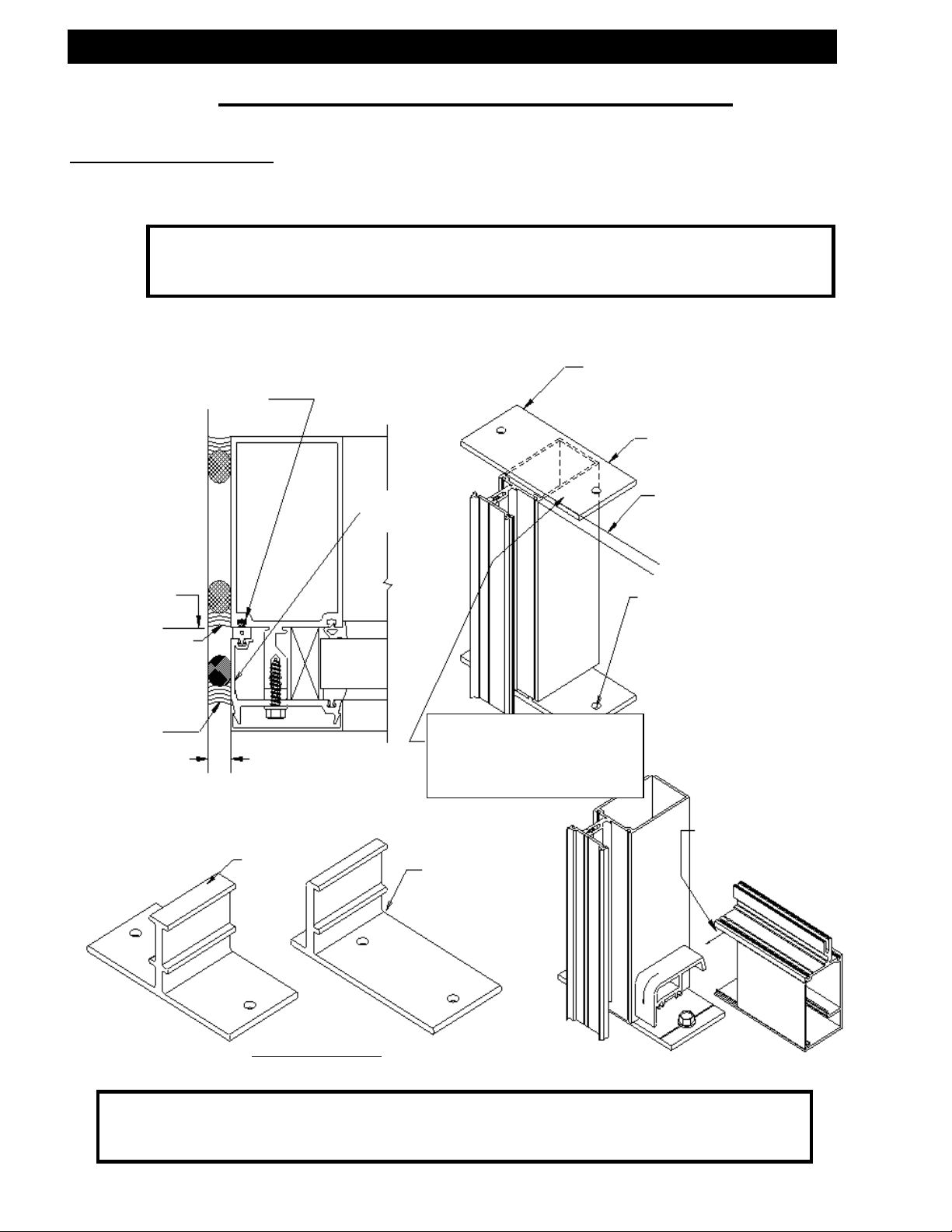
Perimeter Application
A.) For anchoring to perimeter and providing a spacer for glazing pockets at head,
jamb, and sill.
Note: Anchoring surfaces of perimeter constructions must be level and plumb
Fill gasket race with sealant in top
bottom of each vertical mullion to
marry with perimeter sealant.
within the adjustments of the head, jamb, or sill. See “APPROVED” shop
drawings for adjustment limits.
op anchor is recommended
at head connection to
accommodate thermal
movement.
M” Anchor
CRITICAL
SEAL LINE
Primary seal
Optional
cosmetic seal
½” Nominal.
(3/8” Minimum)
M” Anchor
Pressure plate
with return
Erector to supply and apply
bond breaker tape across face
of anchor to prevent 3-sided
sealant adhesion.
F” Anchor
Line of critical
perimeter
sealant shown
Size and locate
anchor bolts in the
field, based on job
conditions and
structural load
requirements.
Filler is cut short to
clear shear block.
Mullion Anchors
Refer to page #8 for further information on
horizontal installation and sealant methods.
Note: The perimeter caulking must be done prior to glazing. Reference the
“APPROVED” shop drawings for caulk joint size unless otherwise specified.
Most sealant manufacturers recommend a 3/8” minimum joint width.
EFCO CORPORATION 6/2012 PART NO. Y354 Page 5 of 23
Page 6
Series 5900 Silicone Structural Glazed Curtain Wall Installation
Section II: Perimeter Application
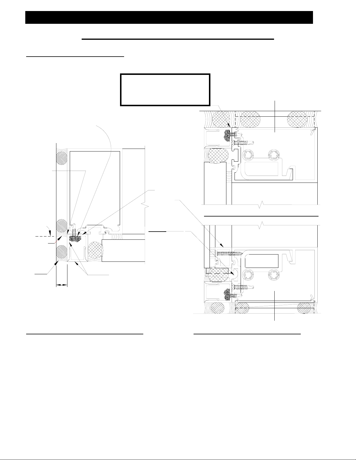
Optional Perimeter Mullions
Cap seal fastener
heads with sealant.
CRITICAL
SEAL LINE.
Primary seal
Optional
cosmetic seal
½” Nominal
3/8” Minimum)
(
Miter adaptor
and filler at
vertical to
horizontal
intersections
and seal
watertight.
Optional Perimeter Jamb Mullion
Perimeter With Channel Adaptor Reveal
Note: The caulking must
overlap the metal to
metal joint at the
critical seal line.
Set adaptors
in sealant
typical.
Note:
Setting
chair
must be
rolled into
position
before
glazing
adaptors.
Optional Perimeter Sill Mullion
Optional Perimeter Head Mullion
EFCO CORPORATION 6/2012 PART NO. Y354 Page 6 of 23
Page 7
g
“
A
g
A
g
Series 5900 Silicone Structural Glazed Curtain Wall Installation
Section III: Anchor Installation
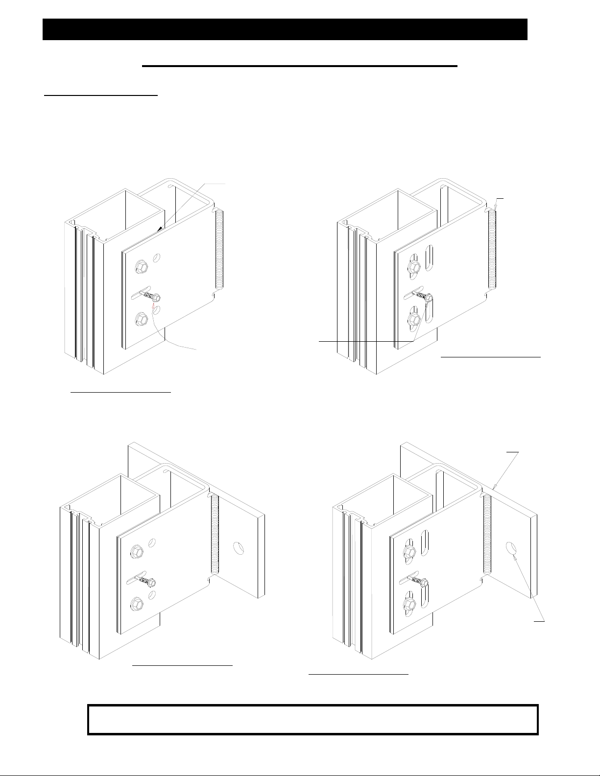
Anchor Installation
A.) Attach anchors to mullions with temporary alignment screws as shown below.
B.) Install the vertical mullions in position and attach anchors to the building structure
per the “APPROVED” shop drawings.
High impact polystyrene
Dead Load Anchors
Welded to building structure
horseshoe shim
fter final alignment
of mullion, align drill
mullion in best hole
location. Note that
the hole must be a
minimum of 1” from
the back of the
mullion to clear any
steel reinforcement
required for the job.
Use #12 X 1” Tek screw
for alignment only. The
screw must be removed
after installation of the
thru bolt at the wind
load anchor to allow for
thermal expansion and
contraction.
Dead Load Anchors
Bolted to building structure
Note: Elevation of slabs must be within adjustment limits of the anchorage
system. See “APPROVED” shop drawings for allowable adjustment.
EFCO CORPORATION 6/2012 PART NO. Y354 Page 7 of 23
Wind Load Anchors
Bolted to buildin
structure
Weld to buildin
structure per
APPROVED”
shop drawings.
Wind Load Anchors
Welded to building structure
steel plate is factory
welded to the channel
anchor and is sized per
the job requirements.
Refer to the “APPROVED”
shop drawings.
Size and locate anchor
bolts based on the job
conditions and structural
requirements. Refer to
the “APPROVED” shop
drawin
s.
Page 8

A
Series 5900 Silicone Structural Glazed Curtain Wall Installation
Section IV: Frame Assembly
Frame Assembly – Captured Horizontals
A.) Assemble shear blocks, splices, anchors, etc., to mullions as required.
B.) Install and anchor vertical mullions to form the vertical sections per “APPROVED”
shop drawings
Note: Check overall frame
dimensions on every 5
openings on long runs to
avoid dimensional build-up.
*
DIMENSION CHECK
EVERY 5 UNITS
Interior horizontals are
cut D.L.O. – 1/32”. The
erector is to split the
difference on both sides.
1” Minimum
Rotate the horizontal over the shear
block from the interior of the
system. With the horizontal in
position, fasten with (1) #10-16 X
1” PLFH Tek3 screw on each end of
horizontal, and tighten as required.
¼” X 1 ½” HWHSMS
pply sealant to the
face and top of the
shear block as shown.
Note: The commercial cut to length tolerance is +- 1/16”.
It is critical to check every 5
Insert front edge of filler into front
race in horizontal. Rotate trailing
edge up and engage into snap.
th
“UNIT” for location.
EFCO CORPORATION 6/2012 PART NO. Y354 Page 8 of 23
OVERALL
DIMENSION CHECK
#10-16 X 1”
PLFH Tek3
Filler
Page 9

A
Series 5900 Silicone Structural Glazed Curtain Wall Installation
Section IV: Frame Assembly
Frame Assembly – Silicone Structural Glazed Horizontals
A.) Assemble shear blocks, splices, anchors, etc., to mullions as required.
B.) Install and anchor vertical mullions to form the vertical sections per “APPROVED”
shop drawings.
Rotate the horizontal over the shear
1” Minimum
block from the interior of the
system. With the horizontal in
position, fasten with (1) #10-16 X
1” PLFH Tek3 screw on each end of
horizontal, and tighten as required.
pply sealant to the
face and top of the
shear block as shown.
¼” X 1 ½” HWHSMS
Note: The commercial cut to length tolerance is +- 1/16”.
It is critical to check every 5
EFCO CORPORATION 6/2012 PART NO. Y354 Page 9 of 23
#10-16 X 1”
PLFH Tek3
th
“UNIT” for location.
Filler
Page 10

p
r
p
A
Series 5900 Silicone Structural Glazed Curtain Wall Installation
V: Vertical Splice Applications
Vertical Splice Joints
A.) Space vertical mullion expansion joints per “APPROVED” shop drawings and in
conjunction with SSG splice locations.
B.) Keep in mind that spacing may vary with job site temperature. On multiple stacked
applications, key horizontals must be installed to establish grades regardless of
expansion joint dimension.
C.) Splice joints should occur at spandrel areas.
D.) Mullion splice joints for this system are not
designed to compensate for varying floor
levels. (Reference “APPROVED”
shop drawings for allowable
adjustment, i.e., anchors.)
Backer rod at
pressure plate
ansion joint
ex
E.) The splice joint width should be
based on sealant movement
capabilities and the following
formula.
Linear expansion for aluminum in
inches = Length X F
(temperature degrees difference
in Fahrenheit) X .0000129.
MULL DIM.MULL DIM.
1/2" EXP. JT.
F.) Where head clearance is
insufficient to allow top mullions
to be lifted over the splice sleeve, a
retractable sleeve will be used. The
sleeve is taped in the top mullion
4" REF.
and dropped to the stop screw in
the mullion below.
G.) Do not match drill anchors until a
check of expansion joints and wall
installation is performed.
EFCO CORPORATION 6/2012 PART NO. Y354 Page 10 of 23
Note: All anchors must be fixed
before glazing begins.
Note: When the mullion splice is
shop installed in the lower
mullion, screws will be used
in the standard location as
shown.
Erector Note: Apply no screws below splice
in the upper pressure plate.
Note: SSG Vertical Splice Locations EFCO
recommends that Vertical Splice Line
be below the Intermediate Horizontal
Member. This will Minimize Shear Stress at
the Structural Seal Line.
2 1/2"
PRESSURE
PLATE SCREWS
SEALANT AT
MULL JOINT
1" MIN.
1"
PRESSURE BAR DIM.PRESSURE BAR DIM.
COVER DIMENSIONCOVER DIMENSION
1/2"
1/2" JT.
1"
3 1/2" MAX.
2"
ttach splice sleeve to
upper mullion with (2)
#10-12 X ¾” PLFHSMS.
Backer rod & sealant at
of lower cove
to
2"
2"
should
4 1/2" SPLICE
Page 11

A
“
Series 5900 Silicone Structural Glazed Curtain Wall Installation
V: Vertical Splice Applications
Vertical Splice Joints at SSG Verticals and Captured Horizontals
A.) Splice should occur at the spandrel areas.
B.) Fabrication Note: Match drill the splice for shear block attachment.
C.) Splice Note: The vertical
mullions that are structurally
glazed must be spliced at the
horizontal locations. (All mullion
splice locations must be
reviewed by a factory
engineer.)
Note: SSG Vertical Splice Locations EFCO
recommends that Vertical Splice Line
be below the Intermediate Horizontal
Member. This will Minimize Shear Stress at
the Structural Seal Line.
D.) Where the head clearance is
insufficient to allow the top
mullions to be lifted over the
splice, a retractable splice will
be used. The splice is taped
into the top mullion and
dropped to a stop screw in the
mullion below. Don’t match
drill the anchors until a check of
the expansion joints and wall
installation is made.
Note: All anchors must be fixed
before glazing begins.
Note: When the mullion splice is
shop installed into the lower
mullion, (2) fasteners will be
used in the standard locations
as shown.
should
MULL DIM.
2 1/2"
1/2" EXP. JT.
MULL DIM.
2 1/2"
A-A” Section Above Splice
5/8"
IF REQUIRED
1" MIN.
A
ttach splice sleeve to upper
mullion with shear block screws
2"
A
4 1/2" SPLICE
2"
EFCO CORPORATION 6/2012 PART NO. Y354 Page 11 of 23
Page 12

“
A
Series 5900 Silicone Structural Glazed Curtain Wall Installation
V: Vertical Splice Applications
Vertical Splice Joints at SSG Verticals and Horizontals
A.) Splice should occur at the spandrel areas.
B.) Fabrication Note: Match drill the splice for shear block attachment.
C.) Splice Note: The vertical mullions that
are structurally glazed must be
spliced at the horizontal locations.
(All mullion splice locations must
be reviewed by a factory
engineer.)
Note: SSG Vertical Splice Locations EFCO
recommends that Vertical Splice Line
be below the Intermediate Horizontal
Member, this will Minimize Shear Stress at
the Structural Seal Line.
should
D.) Where the head clearance is
insufficient to allow the top
mullions to be lifted over the
splice, a retractable splice will be
used. The splice is taped into the
top mullion and dropped to a stop
screw in the mullion below. Don’t
match drill the anchors until a
check of the expansion joints and
wall installation is made.
Note: All anchors must be fixed
before glazing begins.
Note: When the mullion splice is
shop installed into the lower
mullion, (2) fasteners will be
used in the standard locations
as shown.
EFCO CORPORATION 6/2012 PART NO. Y354 Page 12 of 23
2 1/2"
A-A” Section Through Splice
ttach splice sleeve to upper
mullion with shear block
5/8"
2 1/2"
IF REQUIRED
1" MIN.
A
1/2" EXP. JT.
MULL DIM. MULL DIM.
2"
A
2"
4 1/2" SPLICE
Page 13

plug
g
A
j
g
Series 5900 Silicone Structural Glazed Curtain Wall Installation
VI: Glazing Preparation
Glazing Preparation at Structural Glazed Mullions
Note: All thermal isolators should be
Install thermal isolator
prior to installing the
mullion
removed from the reels and allowed
to shrink prior to installation.
s.
Prior to installin
seal all three sides of the plug,
making sure all cavities are filled.
With sealant in place, the mullion
plugs can be installed.
Provide a downward slope with the
sealant, without interfering with
the edge of the glass, to allow for
drainage of condensation.
Closed cell sponge joint plug
Seal the
direction at all corners with
sealant, making sure that all
fastener heads are sealed.
asket race 2” in each
Elevation of Joinery at the S.S.G.
Mullion Prior to Setting the Glass
the mullion plugs,
Edge of glass
Prior to installing the mullion plugs,
seal all three sides of the pocket,
making sure all cavities are filled.
2"
pply sealant to the face of the
oint plug prior to installation of the
pressure plate. See page #19.
EFCO CORPORATION 6/2012 PART NO. Y354 Page 13 of 23
Page 14

g
y
)
g
A
Series 5900 Silicone Structural Glazed Curtain Wall Installation
VI: Glazing Preparation
Glazing Preparation At Captured Mullions
A.) Install the thermal isolator in the vertical
mullion, run continuously, and butt joint
as required.
B.) Seal vertical mullion raceway 1” long
prior to the installation of the joint
plugs.
C.) Place and seal the joint plug.
D.) Tool off all excess sealant.
E.) Apply sealant to the face
of the joint plug prior to
installation of the pressure
plate. See page #19.
Provide a downward slope with
sealant, without interferin
the edge of the glass, to allow
for drainage of condensation.
Closed cell sponge joint plugs
Seal gasket race 2” in each
direction at all corners with
sealant, making sure that all
fastener heads are sealed.
(Captured system shown,
SSG s
Note: Each daylite opening should
be sealed individually with
gaskets and glazing installed
immediately following with
pressure at the corners.
stem similar.
Elevation of Joinery Prior to Setting the Glass
Seal vertical mullion
asket raceway 1” prior to
installation of joint plugs.
with
2"
Place and seal the mullion plug. Prior to
installation, apply sealant on all contact
surfaces, and tool off excess sealant to
prevent obstructing the water path.
Edge of glass
2"
pply sealant to the face of
the joint plug prior to the
installation of the pressure
plate. See page #19.
EFCO CORPORATION 6/2012 PART NO. Y354 Page 14 of 23
Page 15

V
r
g
Series 5900 Silicone Structural Glazed Curtain Wall Installation
VII: Glazing Adaptors
Installation of Glazing Adaptors at Silicone Structural Glazed Mullions
A.) Vertical adaptor length without a
mullion expansion joint equal
D.L.O. plus 1”.
B.) Vertical adaptor length with a
mullion expansion joint, see the
“APPROVED” shop drawings.
C.) Horizontal adaptor length equal
D.L.O. minus 1/16”.
D.) Install the vertical
adaptors first, and attach
with #8 X 1 ¼” PLPH SMS
at a minimum of 18” on
center. (Seal fastener
heads with sealant.)
ertical Adaptor
E.) Install the horizontal adaptors
between the vertical adaptors.
Horizontal Adapto
Installation of Glazing Adaptors at Captured Mullions
Set all adaptors in a continuous
bead of sealant, and seal all
vertical to horizontal adaptor
intersections.
A.) Position the vertical adaptors as
shown.
B.) Place horizontal adaptors
between the verticals.
C.) Seat adaptors by applying sealant
to all four corners.
D.) Cut formula for vertical adaptors
equal D.L.O. plus 1”. Horizontal
adaptors equal D.L.O. minus
1/16”.
Note: Vertical adaptors need a minimum
of 1/8” clearance above the
mullion plug, free from sealant.
Continuously seal the
gasket raceway with
sealant prior to
installin
the adaptors.
EFCO CORPORATION 6/2012 PART NO. Y354 Page 15 of 23
Page 16

Series 5900 Silicone Structural Glazed Curtain Wall Installation
VIII: Sealant At Splice Joint
Installation of Backer Rods at Structurally Glazed Mullion Splices
Expansion joint
Splice sleeve
Note: At corner mullions, use
more than one backer rod
as required, and miter it to
fit the corner joint.
Note: Each daylite opening should
Closed cell sponge joint plug
be sealed individually with
gaskets and glazing installed,
immediately followed with
pressure at the corners.
Install backer rod foam
at expansion joint.
½” Between adaptors
Expansion joint
Install backer rod foam
Splice sleeve
at expansion joint.
Reference pages 11 through 13 for mullion splice detail.
EFCO CORPORATION 6/2012 PART NO. Y354 Page 16 of 23
Page 17

r
Series 5900 Silicone Structural Glazed Curtain Wall Installation
IX: Preset Gaskets
Apply Preset Glazing Gaskets to Mullions
A.) Apply sealant into gasket race a minimum of 2” each direction at each corner.
B.) Remove glazing gaskets
from the reel and allow to
shrink.
C.) Cut vertical gaskets D.L.O.
plus 1 ¾”.
D.) Cut horizontal gaskets
D.L.O. plus ½”.
E.) Seal all gasket corners: Pull
horizontal gaskets back, seal end,
and compress into the vertical
gasket to insure a snug fit.
Note: If the gaskets are difficult to
insert into the gasket race, a
light coat of mineral spirits
can be applied to the gasket
for lubrication.
F.) Cut horizontal gaskets at
structural glazed mullions
D.L.O. plus ½”. Cut
vertical spacers to D.L.O.
plus 1 ¼”.
Preset space
EFCO CORPORATION 6/2012 PART NO. Y354 Page 17 of 23
Preset gaskets
Preset gaskets
Page 18

V
Series 5900 Silicone Structural Glazed Curtain Wall Installation
X: Miscellaneous Applications
Clean
A.) Clean all metal and infill surfaces that will come in contact with the structural
silicone sealant with the proper cleaner.
B.) Apply silicone primer as recommended by the silicone manufacturer.
Setting Blocks
A.) Position and install the setting blocks per the “APPROVED” shop drawings.
Position Glazing Infill
A.) Set the glazing infill into the framing opening tight against the interior gasket,
and position squarely onto the setting blocks.
Gaskets to Pressure Plates
A.) Apply the glazing gasket to the pressure plates.
B.) The gaskets applied to the vertical pressure plates are to be cut flush at both
ends, except in multi-story applications where gaskets are to extend 1” beyond
the end at expansion joints.
C.) The gaskets applied to horizontal pressure plates are cut ¼” long, both ends
maximum.
ertical Gasket
Preset gasket
Note: The vertical gasket runs through the joint
plug notch at the horizontal location. Seal
Mull plug
all corners of the gaskets with sealant.
D.) Apply sealant to the face of the mullion plug prior to installing the vertical or
horizontal pressure plate.
EFCO CORPORATION 6/2012 PART NO. Y354 Page 18 of 23
Page 19

k
p
g
”
Series 5900 Silicone Structural Glazed Curtain Wall Installation
XI: Pressure Plate Attachment
Pressure Plate Attachment
A.) Attach pressure plates with ¼” X 1” stainless steel hex washer head pressure
plate screws. Typical spacing is 6” on center.
B.) Torque all pressure plate screws to 80 inch pounds. In cold weather, first torque
all screws to 40 inch pounds. When possible, work from the center outward on
horizontal and from sill upward on verticals. Then torque all screws to 80 inch
pounds after all four sides of the opening have been clamped.
½” Glass Bite
(typical)
1/8
3/16” X 1” weep slot
centered 4” off each
end of the pressure
plate.
½” Glass Bite
(typical)
1/8”
OPTIONAL WEEP HOLES
5/16” dia. weep holes
Drill 3 side by side centered
Line of Mullion
Edge of Glass
4” off each end of pressure
plate. Locate C/L of holes
5/32” above to
of tongue.
Line of Mullion
Ed
e of Glass
Erector Note: Special structural dual seals are required
for structural glazing infill. The insulated glass
may require a structural sealant bead at the
spacer. This will be determined by job specific
information, such as design pressure, infill lite
size, and other pertinent information. Consult the
glass supplier and or manufacturer for specific
application recommendations.
Customer / Installer Note:
EFCO setting blocks are
typically 4” in length with
Setting bloc
Glass line
different depths. If the
glazing infill is “NOT BY
EFCO” and glazing sizes are
larger than 40 square feet,
then the glazing details
must be reviewed by the
glazing manufacturer for
proper setting block size.
EFCO CORPORATION 6/2012 PART NO. Y354 Page 19 of 23
Page 20

p
g
Series 5900 Silicone Structural Glazed Curtain Wall Installation
XI: Pressure Plate Attachment
C
MULL
Pressure Plate Attachment
4" TYPICAL
Seal joints
with sealant
Note: Reference pages 11 through 13 for recommended pressure plates at splice
locations. Install the first screw approximately 3” from the end. Typical screw
spacing is 6” on center. The glazier should always insert a screw in the vertical
pressure plate directly opposite each horizontal, to provide maximum control of
pressure on the mullion plugs, which provide a critical sealing function.
L
2 1/2"
1/4"
Weep slots
Customer / Installer Note:
EFCO setting blocks are
typically 4” in length with
different depths. If the
glazing infill is “NOT BY
EFCO” and glazing sizes are
larger than 40 square feet,
then the glazing details
must be reviewed by the
glazing manufacturer for
proper setting block size.
¼” x 1”
HWHSMS
Settin
Seal the horizontal pressure
plate to the vertical pressure
late to be air and watertight.
EFCO CORPORATION 6/2012 PART NO. Y354 Page 20 of 23
block
Glass line
Page 21

Series 5900 Silicone Structural Glazed Curtain Wall Installation
XII: Temporary Retainers and Sealant
Temporary Retainers
A.) Temporary retainers are supplied by EFCO based on the lineal footage of
structural glazed members divided by 2.
B.) The location of the temporary exterior infill retainers should not exceed a
maximum of 24”* on center. *(If high wind conditions are anticipated, additional
retainers may be required. Please consult the sealant and /or glazing infill
supplier for spacing recommendations.)
Erector Note: Special structural dual seals are required for structural glazing infill.
The insulated glass may require a structural sealant bead at the spacer. This
will be determined by job specific information, such as design pressure, infill
lite size and other pertinent information. Consult the glass supplier and or
structural sealant manufacturer for specific application recommendations.
Apply The Structural Silicone Sealant
A.) EFCO does not supply sealant.
B.) The sealant is to be a structural silicone as recommended by the sealant
manufacturer.
C.) The infill and metal is to be cleaned per the silicone manufacturer’s
recommendations.
D.) Allow the structural silicone seal to cure per the manufacturer’s
recommendations before removing the temporary glazing retainers.
Exterior Weather Seal
A.) Install backer rod between the two insulated infill units or bond breaker tape
behind the monolithic infills. (Not By EFCO)
B.) Apply the exterior weather seal as recommended by the sealant manufacturer.
NOTE: Seal up to the temporary retainers. After the structural sealant cures,
remove the temporary retainers, and seal the remaining gaps.
Reversible temporary glazing retainer
EFCO CORPORATION 6/2012 PART NO. Y354 Page 21 of 23
Weather sealBond breaker tapeWeather sealBacker rod
Page 22

A
g
V
A
Series 5900 Silicone Structural Glazed Curtain Wall Installation
Section XIII: Exterior Cover Installation
Snap-On Exterior Covers
A.) Set vertical covers as shown on “APPROVED” shop drawings.
7/16"
B.) Center the horizontal snap cover in the opening, align and
engage one side, then use a block and mallet to engage
the opposite side.
C.) Gaps at the ends should be equalized
and are provided to allow installation,
thermal movement, and weepage.
D.) Exterior horizontal covers are cut
D.L.O. – 1/16”.
E.) The erector is to split the
difference on both ends.
Drill 5/16”
diameter weep
holes in the
horizontal covers
2” from each end.
Note: Care must be taken
to avoid damage to
the covers during
installation. Use a
nominal 12” long 2
X 4 and mallet or
hammer to seat the
cover.
ertical cover
pprox. 12” long
wood block
Mallet or hammer
Horizontal
cover
Equal space at both ends
of horizontal cover
Note: Horizontal covers 1” or
more in depth must be
mechanically attached,
similar to detail below.
1/16” X 5/16” roll pin at the center of the
cut length is recommended to prevent
slippa
horizontal to eliminate exposure.
e. The roll pin can be located at the
EFCO CORPORATION 6/2012 PART NO. Y354 Page 22 of 23
Page 23

Series 5900 Silicone Structural Glazed Curtain Wall Installation
Section XIV: Steel Reinforcement
Steel Reinforcement
A.) At large spans or in high wind load areas, steel reinforcement may be necessary.
B.) Reinforcement requirements will vary on a per job basis.
C.) Reference the “APPROVED” shop drawings for steel requirements and locations.
D.) When steel reinforcement is factory installed in the mullions, use fasteners to
prevent damage or slippage of the steel during shipping.
EFCO CORPORATION 6/2012 PART NO. Y354 Page 23 of 23
 Loading...