

Page 1
Y
Series 5600
Sloped glazed Curtain wall
Installation Instructions
Part NO.
February 2013
308
Page 2

Series 5600 Slope Glazed Curtain Wall Installation Instructions
TABLE OF CONTENTS
SECTION PAGE
I. General Notes & Guidelines …………………………………………………. 3-4
II. Gutter and Mullion Assembly .…….………………………………………… 5
III. End Cap Installation …………………………………………………………… 6-7
IV. Rafter and Purlin Assembly .………………………………………………… 8-9
V. Purlin Assembly …………………………………………………………………..10-14
VI. PVC Isolator and Gasket Application ……………………………………. 15-16
VII. Glazing Instructions …………………………………………..………………. 17-21
VIII. Snap On Exterior Covers ………………………….………………………… 22-23
Note: Please reference EFCO's "Understanding Condensation" brochure which can be obtained
through your EFCO representative.
Condensation will form on any surface when unfavorable conditions (interior temperature
and relative humidity and exterior temperature) are present. When the formation of excessive
condensation is a concern, it is highly recommended that a design professional is utilized to
perform an analysis of the shop drawings to recommend the best possible installation methods.
Please contact your EFCO representative for information on EFCO's Thermal Analysis Services.
Many current installation practices lead to an increase in the possibility of the formation of
condensation. Though not all inclusive, the list of examples below illustrates conditions under
which condensation is likely to occur:
1. Bridging system thermal break with non-thermally broken metal flashing or lintels
that are exposed to the exterior
2. System exposure to cold air cavities
3. Interior relative humidity levels not maintained at recommended levels, see EFCO’s
“Understanding Condensation” brochure
4. Inadequate separation between system and surrounding condition at perimeter
5. Product combinations during the shop drawing stage that result in bridging thermal
breaks of one or all products involved
Minimizing Condensation
EFCO CORPORATION 6/2012 PART NO. Y308 Page 2 of 23
Page 3

Series 5600 Slope Glazed Curtain Wall Installation Instructions
Section I: General Notes & Guidelines
I. HANDLING / STORING / PROTECTING ALUMINUM - The following
precautions are recommended to assure early acceptance of your products and
workmanship.
A. HANDLE CAREFULLY - Store with adequate separation between
components so the material will not rub together. Store material off the
ground. Protect materials against weather elements and other construction
trades.
B. KEEP MATERIAL AWAY FROM WATER, MUD, AND SPRAY - Prevent
cement, plaster, and other materials from contacting with and damaging the
finish. Do not allow moisture to be trapped between the finished surface and
the wrapping material.
C. PROTECT MATERIALS AFTER ERECTION - Wrap or erect screens with
plastic sheeting over material. Cement, plaster, terrazzo, and other alkaline
materials are very harmful to the finish and are to be removed with soap and
water before hardening. Under no circumstances should these materials be
allowed to dry or permanent staining will occur.
II. GENERAL GUIDELINES - The following practices are recommended for all
installations:
A. REVIEW APPROVED SHOP DRAWINGS – Become thoroughly familiar
with the project. Shop drawings govern when conflicting information exists in
these installation instructions.
B. INSTALL ALL FRAMING MATERIAL PLUMB, LEVEL, AND TRUE –
Proper alignment and relationships to benchmarks and column centerlines, as
established by the architectural drawings and the general contractor, must be
maintained.
C. The sequence of erection should be coordinated with the project
superintendent to prevent delays and minimize the risk of material damage.
Note: If preset anchors are required, coordinate and supervise
anchor placement with the general contractor.
D. Verify that all job site conditions and accompanying substrates receiving the
installation are in accordance with the contract documents. If deviations
occur, notification must be given IN WRITING to the general contractor and
differences resolved before proceeding further with the installation in the
questionable area.
E. Prevent all aluminum from coming in direct contact with masonry or dissimilar
materials by means of an appropriate primer.
EFCO CORPORATION 6/2012 PART NO. Y308 Page 3 of 23
Page 4

Series 5600 Slope Glazed Curtain Wall Installation Instructions
Section I: General Notes & Guidelines
F. Follow EFCO framing installation and glazing instructions.
G. Verify contents of all material shipments received upon arrival. Verify quantity
and correct finishes. NOTIFY EFCO IMMEDIATELY OF ANY
DISCREPANCIES OR DAMAGE, THAT MAY HAVE OCCURRED.
H. Throughout these instructions the term “SEALANT” will appear. For the
purposes of these instructions, sealant is to be defined as the following:
SEALANT - A weather resistant, gunnable liquid filler which when cured
provides a resilient, flexible (± 50% movement capability) air and water seal
between similar and dissimilar materials.
All sealant must meet ASTM C 920, CLASS 50.
BUTYL SEALANT- A non-skinning, non-hardening material (NAAMM
Reference Standard 5C-1)
NOTE: All sealant must be compatible with all surfaces where adhesion is
required, including other sealant surfaces. All frame surfaces should
be clean, dry, dust, and frost free. If a primer is required, it must be
applied to clean surfaces. All perimeter substrates shall be clean and
properly treated to receive sealant.
This system is designed and has been tested to utilize butyl or
silicone sealants at all internal joineries, i.e., joint plugs, gasket
intersections, etc.
Regardless of the sealant used, the customer should contact the
sealant manufacturer to determine compatibility and adhesion.
Follow sealant manufacturer's proper application procedures and
quality assurance programs for weather sealing.
Maintain caulk joints as shown in the approved shop drawings.
Unless specified otherwise, most sealant manufacturers recommend
a 3/8” minimum perimeter caulk joint. A 3/4” minimum joint is
recommended at the head condition to accommodate thermal
expansion and contraction.
Anchoring surfaces of perimeter construction must be level and
plumb within the adjustable limits of the head, jamb, and sill
framing.
EFCO CORPORATION 6/2012 PART NO. Y308 Page 4 of 23
Page 5
T
r
Series 5600 Slope Glazed Curtain Wall Installation Instructions
Section II: Gutter and Mullion Assembly
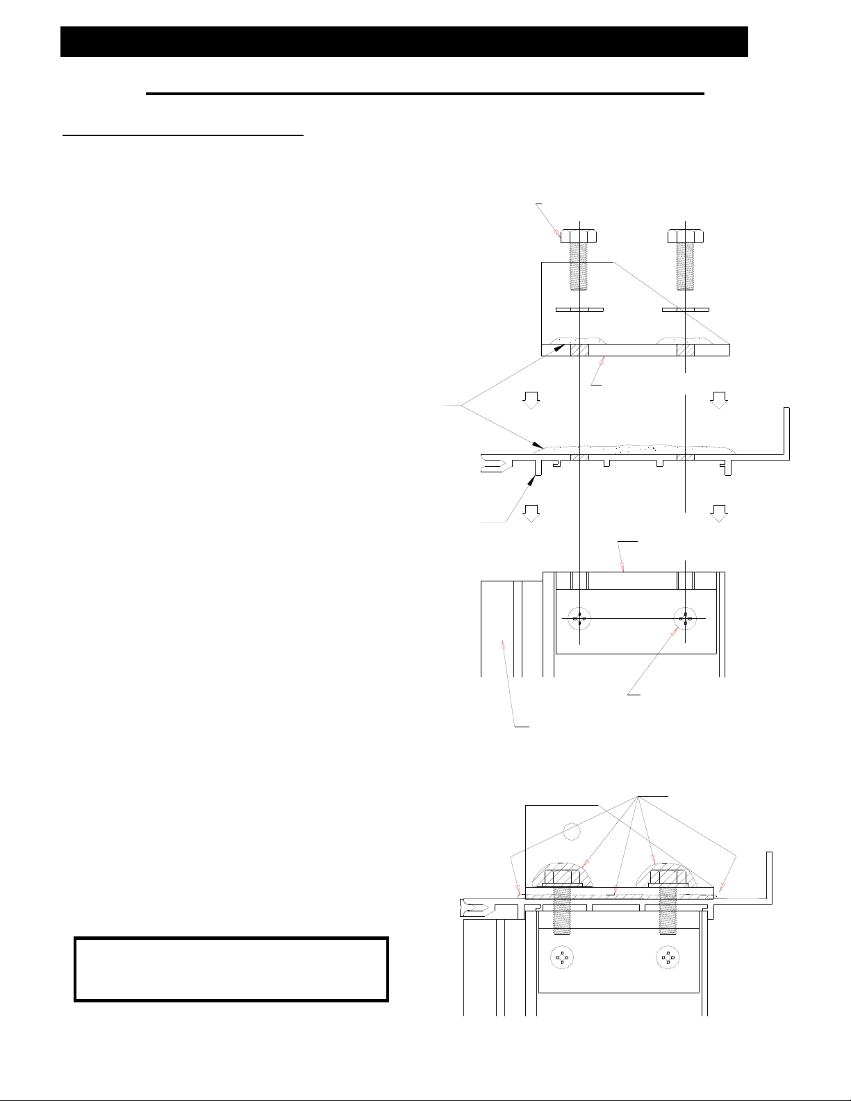
Gutter and Mullion Assembly
A.) Insert the transition anchor in top of 5600
wall vertical mullion using (4) #14 flat
head countersunk screws. (Ref. Fig. #1)
B.) At extreme jamb members attach .062
aluminum end cap to top of mullion with
(2) #8 countersunk screws. Line up end
cap as shown below. (Ref. Fig. #3)
Bed of sealant
at clip locations.
Transition gutter
C.) Prior to setting clip assembly, clean all
metal surfaces and lay in a bed of silicone
sealant at clip location. Set washers in
silicone sealant on top of gutter clip.
Insert 3/8” diameter bolts through flat
washer, gutter clip, transition gutter and
secure to transition anchor as shown.
(Ref. Fig. #1 & #2)
D.) Seal over bolt heads & washers then tool
excess sealant around perimeter edge of
gutter clip to insure proper seal.
Note: Primer may be needed on mill
finish material, consult sealant
manufacturer.
EFCO CORPORATION 6/2012 PART NO. Y308 Page 5 of 23
3/8” Diameter bolts & flat washers
Gutter clip, sized
and cut per job.
ransition ancho
[FIG. 1]
Typical 5600
curtain wall
mullion.
[FIG. 2]
(4) #14 countersunk
screws per anchor.
Tooled sealant.
Page 6

Series 5600 Slope Glazed Curtain Wall Installation Instructions
Section III: End Cap Installation
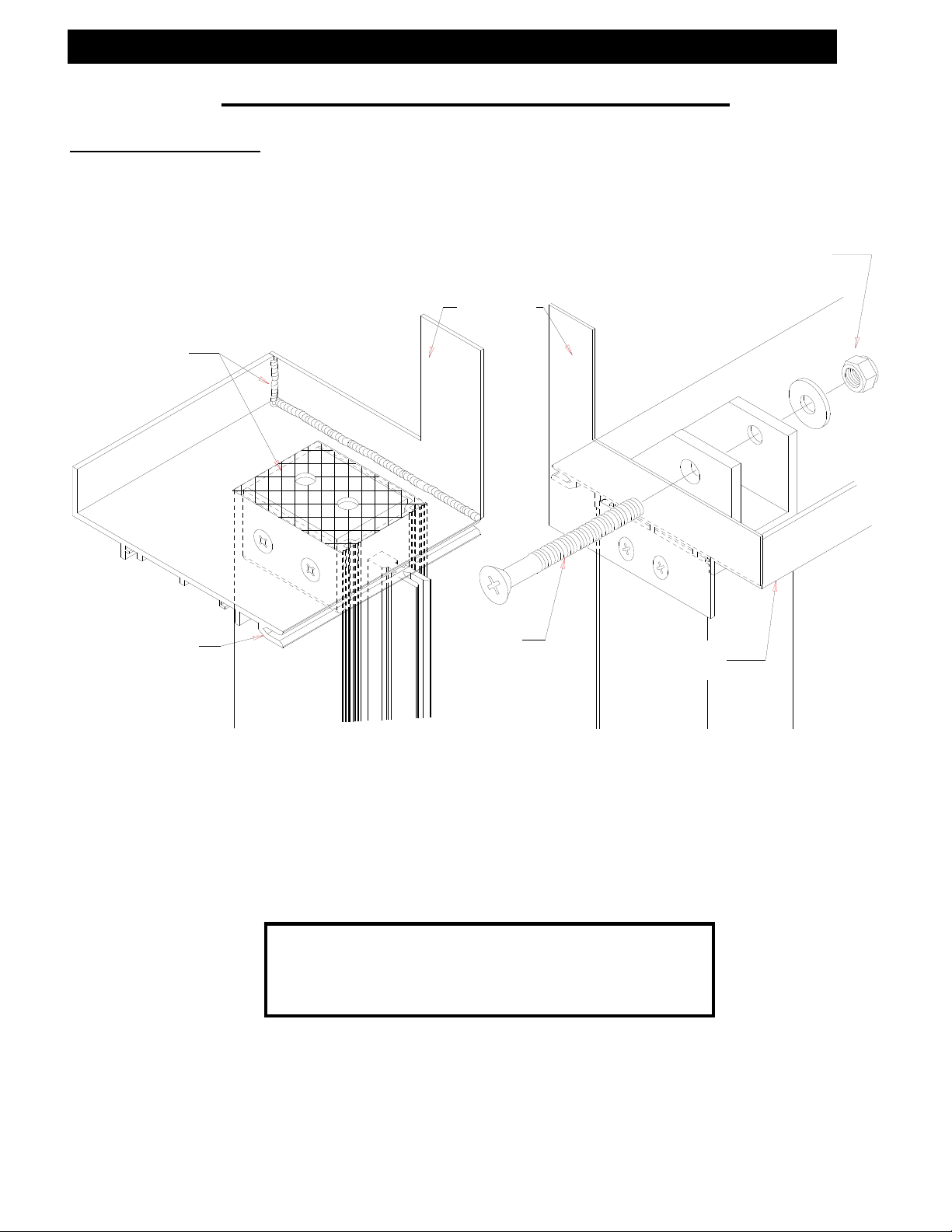
End Cap Installation
End cap
End cap as designed
on a per job basis.
T.O. Mullion
1"
1/8"
Location of gutter
once installed on top
of vertical mullion.
5"
#8 Flat head
countersunk screws.
[FIG. 3]
of mullion
Inside edge
A.) Seal joint between gutter and end cap as shown. When jamb condition is exposed
(end wall condition), use a 3/8” diameter X 3” long countersunk bolt to secure the
lower rafter clip to the gutter clip. This will allow for overlap of flashing as
designed.
EFCO CORPORATION 6/2012 PART NO. Y308 Page 6 of 23
Page 7
T
Series 5600 Slope Glazed Curtain Wall Installation Instructions
Section III: End Cap Installation
End Cap Installation
End Cap
Sealant
Self – locking nut
ransition gutter
3/8” X 3”
Flat head
Transition gutter
S-5600 Wall MullionS-5600 Wall Mullion
[FIG. 4]
Note: Refer to typical S-5600 Wall Installation
Instructions for procedures regarding
installation of curtain wall above or below
slope glazing system.
EFCO CORPORATION 6/2012 PART NO. Y308 Page 7 of 23
Page 8

r
Series 5600 Slope Glazed Curtain Wall Installation Instructions
Section IV: Rafter and Purlin Assembly
Rafter and Purlin Assembly
A.) Slide lower rafter clip in bottom end of rafter and attach with (4) #14 countersunk
screws. (Ref. Fig. #5)
EFCO CORPORATION 6/2012 PART NO. Y308 Page 8 of 23
Note: Anchor conditions vary on
a per job basis. Refer to
“APPROVED” shop
drawings for actual
anchoring conditions, and
attach accordingly.
#14 X ¾” FHSMS
B.) Insert extruded anchor clip into top
of rafter and temporarily tape in
position until ready for permanent
attachment. (Ref. Fig. #5)
Note: Do not attach anchor clips
to top of rafter with thru
bolts until the rafter is
secured in final position.
Rafte
Lower Rafter Clip
[FIG. 5]
Page 9

T
r
–
T
r
Series 5600 Slope Glazed Curtain Wall Installation Instructions
Section IV: Rafter and Purlin Assembly
Rafter and Purlin Assembly
C.) Slide rafter and lower rafter clip assembly over gutter clip and align pre-fabricated
3/8” through bolt holes, install 3/8” X 3” hex bolt, washers & self-locking nuts as
shown in figure #6
Rafte
Lower Rafter Clip
ransition Gutter
3/8” X 3”
Hex bolt
ransition Ancho
locking nut
Self
Gutter Clip
[FIG. 6]
EFCO CORPORATION 6/2012 PART NO. Y308 Page 9 of 23
Page 10

Series 5600 Slope Glazed Curtain Wall Installation Instructions
Section V: Purlin Assembly
Purlin Assembly
Note: Slide purlin over stiffener tube where applicable prior to sealing.
A.) Install all horizontal purlins at head, intermediates and transition, being careful to
seal as indicated. (Ref. Figs. #8, 9, 10, 11, & 12)
[FIG. 8]
Sealant
Seal underside of each purlin as shown prior
to setting in notch. Make sure that slide –
in grooves of purlin are completely full of
sealant.
[Critical Seal]
EFCO CORPORATION 6/2012 PART NO. Y308 Page 10 of 23
Page 11

A
Series 5600 Slope Glazed Curtain Wall Installation Instructions
Section V: Purlin Assembly
Purlin Assembly
B.) Snap-on purlin retainer clips at each end of purlin as shown. (Ref. Figs. #9 & 10)
luminum purlin retainer clips
Lay a bed of sealant in
notch on rafter prior to
setting horizontal purlin.
[FIG. 9]
EFCO CORPORATION 6/2012 PART NO. Y308 Page 11 of 23
Page 12

r
Series 5600 Slope Glazed Curtain Wall Installation Instructions
Section V: Purlin Assembly
Purlin Assembly
Note: Tool underside of purlin seal with
putty knife to insure a complete seal.
Purlin Retainer Clips
Horizontal Purlin
Rafte
[FIG. 10]
EFCO CORPORATION 6/2012 PART NO. Y308 Page 12 of 23
Page 13

r
A
T
Series 5600 Slope Glazed Curtain Wall Installation Instructions
Section V: Purlin Assembly
Purlin Assembly
luminum Purlin Clip
ransition Purlin
Purlin notch in rafte
C.) Install all horizontal purlins at head,
intermediates and transition being
careful to seal as indicated.
(Ref. Figs. #8, 9, 10, 11 & 12)
D.) Snap-on purlin retainer clips at each end
1.250
of purlin as shown. (Ref. Figs. #8 & 9)
Note: Make sure the clips are secured in
position in order to hold down purlins.
[FIG. 11]
EFCO CORPORATION 6/2012 PART NO. Y308 Page 13 of 23
Page 14

j
T
Series 5600 Slope Glazed Curtain Wall Installation Instructions
Section V: Purlin Assembly
Purlin Assembly
Sealant at joint.
Purlin Retainer Clip
[FIG. 12]
Notched at
ambs only
Weep holes.
(Ref. shop
drawings for
locations)
This
End
Down
ransition Purlin
EFCO CORPORATION 6/2012 PART NO. Y308 Page 14 of 23
Page 15

Series 5600 Slope Glazed Curtain Wall Installation Instructions
Section VI: PVC Isolator & Gasket
PVC Isolator and Gasket Application
A.) Insert appropriate gasket and isolator into rafter and purlins as shown.
(Ref. Figs. 13A & 13B)
B.) Gaskets can become somewhat deformed during storage in cartons. They should
be removed from cartons and / or rolls several hours prior to use, lay flat or hang
so as to allow for recovery of correct shape. Temperatures should be at least 50
degree to allow for recovery.
C.) * DO NOT STRETCH GASKETS out of shape. Cut approximately 1/8” longer per
foot and work from ends to the center. Then trim off excess. (Ref. Fig. 14)
Interior
Preset
Gasket
Isolator
[FIG. 13B]
EFCO CORPORATION 6/2012 PART NO. Y308 Page 15 of 23
[FIG. 13A]
Page 16

Series 5600 Slope Glazed Curtain Wall Installation Instructions
Section VI: PVC Isolator & Gasket
PVC Isolator and Gasket Application
D.) Fit gaskets and isolators between purlin retainer clips. (Ref. Fig. #14)
E.) Seal joints as indicated.
Seal joint between
vertical rafters and
purlins.
Butt and bed gaskets
with sealant
[FIG. 14]
EFCO CORPORATION 6/2012 PART NO. Y308 Page 16 of 23
Page 17

Series 5600 Slope Glazed Curtain Wall Installation Instructions
Section VII: Glazing Instructions
Glazing Instructions
A.) Place setting blocks in position at ¼ points in intermediate and transition purlins.
(Ref. Fig. #15)
Customer / Installer Note: EFCO setting blocks are
typically 4" in length with different depths. If the glazing
infill is "NOT BY EFCO"
40 square feet, then the glazing details must be reviewed
by the glazing manufacturer for proper setting block size.
and glazing sizes are larger than
Setting blocks
at ¼ points.
[FIG. 15]
EFCO CORPORATION 6/2012 PART NO. Y308 Page 17 of 23
Page 18

,
Series 5600 Slope Glazed Curtain Wall Installation Instructions
Section VII: Glazing Instructions
Glazing Instructions
B.) Set all glass units in position, being careful to center in D.L.O.
(Typical glass bite is ½”) (Glass size = D.L.O. + 1”)
Note: Temporary Glazing Retainers are available from
EFCO. These retainers are considered an extra
and can be provided at customer’s request.
EFCO CORPORATION 6/2012 PART NO. Y308 Page 18 of 23
Page 19

g
Series 5600 Slope Glazed Curtain Wall Installation Instructions
Section VII: Glazing Instructions
Glazing Instructions
C.) Install transition pressure plate, flashing, and any
other infill as required prior to final assembly.
(Ref. Figs. 16A & 16B)
Note: Set transition pressure plate in full bed of
sealant at gutter and end cap locations.
(Ref. Fig. 16A)
Closure Angle
Transition
Pressure
Plate
Bed of
sealant
[FIG. 16A]
Sealant
End Cap as
ned on a
desi
per job basis.
[FIG. 16B]
EFCO CORPORATION 6/2012 PART NO. Y308 Page 19 of 23
Page 20

Series 5600 Slope Glazed Curtain Wall Installation Instructions
Section VII: Glazing Instructions
Glazing Instructions
D.) Apply glazing gaskets to pressure plate. Gaskets applied to rafter pressure
plate must be cut flush at both ends. Gaskets applied to purlin pressure
plates cut ¼” long both ends maximum.
Exterior
Preset
Gasket
Infill Infill
Rafter
E.) Refer to Fig. #14 to insure that sealant is at rafter to purlin joinery as
illustrated.
Infill
Infill
Purlin
EFCO CORPORATION 6/2012 PART NO. Y308 Page 20 of 23
Page 21

Series 5600 Slope Glazed Curtain Wall Installation Instructions
Section VII: Glazing Instructions
Glazing Instructions
F.) Install pressure plates. Attach pressure plate to rafters and purlin with
screws at 6” O.C. typical.
Note: In cold weather, first torque all pressure plate fasteners at 40 inch
pounds. When possible work from center outward on purlins and from
transition upwards on rafters. Then torque all screws to 80 inch pounds.
After all four sides all four sides of opening having been clamped
#13 X 5/8 long
screws at 6” O.C.
Seal all joints
with sealant.
EFCO CORPORATION 6/2012 PART NO. Y308 Page 21 of 23
Page 22

A
g
Series 5600 Slope Glazed Curtain Wall Installation Instructions
Section VIII: Snap-On Exterior Covers
Snap-On Exterior Covers
A.) Install Vertical Rafter Covers…
Caution: Care must be taken
to avoid damage to covers
during installation. Use a
nominal 12” long 2 X 2 or 2 X
4 and mallet to seat covers.
Mallet or
hammer.
pproximately
12” lon
block
of wood.
B.) Install Horizontal Purlin Covers…
Silicone sealant
continuous for
drainage.
EFCO CORPORATION 6/2012 PART NO. Y308 Page 22 of 23
Page 23

V
r
Series 5600 Slope Glazed Curtain Wall Installation Instructions
Section VIII: Snap-On Exterior Covers
Snap-On Exterior Covers
C.) After installation of purlin covers, seal as shown above for water drainage.
Reseal pressure plate to vertical
covers prior to attaching
horizontal covers.
ertical Cove
Horizontal
Cover
D.) Center horizontal snap cover in opening;
engage one side, then use block and
Equally Space
both ends of
horizontal covers.
mallet to engage opposite side. Gaps at
ends should be equalized, and are
provided to allow installation, to allow
thermal movement, and provide
weepage.
1/32"
EQUALEQUAL
1/32"
EFCO CORPORATION 6/2012 PART NO. Y308 Page 23 of 23
 Loading...