

Page 1

Y
Series 5500
Advanced and alternate
Installation Instructions
Part NO.
February 2013
557
Page 2

Series 5500 Advanced & Alternate Installation Instructions
TABLE OF CONTENTS
S-5500 ADVANCED INSTALLATION INSTUCTIONS
SECTION PAGE
I. General Notes and Guidelines………………………………………...……... 3-4
II. Frame Unit Assembly & Frame Sealing
Shear Block……………………………………...…………………………………. 5-6
III. Alternate Anchorage Methods
Sleeve Anchors………………………………………………………………….. 7-10
Mull Anchors …………………………………………………………………… 11-17
IV. Punched Opening & Ribbon Windows
Frame Unit Assemble & Frame Sealing..………….……………………18-20
Alternate Anchorage Method……………………………………………… 21-23
V. Vertical Splice Joints……………………………………………………………. 24-33
VI. Expansion Mullions…………………………………...………………………... 34-37
VII. Glazing At Spandrel Areas of Inside Glazed Frames ……………….. 37-40
VIII. Glazing Adaptors
Captured Glazing………………………………………………………………….. 41
Silicone Structural Glazed …………………………………………………. 43-46
Note: Please reference EFCO's "Understanding Condensation" brochure which can be obtained through your EFCO
representative.
Condensation will form on any surface when unfavorable conditions (interior temperature and relati ve humidity and
exterior temperature) are present. When the formation of excessive condensation is a concern, it is highly recommended that a
design professional is utilized to perform an analysis of the shop drawings to recommend the best possible installation methods.
Please contact your EFCO representative for inf ormation on EFCO's Thermal Analysis Services.
Many current installation practices lead to an increase in the possibility of the formation of condensation. Though not all
inclusive, the list of examples below illustrates conditions under which condensation is likely to occur:
Note: This document is to be used in conjunction with the standard installation
instructions.
Note: These installation instructions are a supplement to the approved final shop drawings
and are to be used in conjunction with those drawings.
Minimizing Condensation
1. Bridging system thermal break with non-thermally broken metal flashing or lintels that are exposed to the
exterior
2. System exposure to cold air cavities
3. Interior relative humidity levels not maintained at recommended levels, see EFCO’s “Understanding
Condensation” brochure
4. Inadequate separation between system and surrounding condition at perimet er
5. Product combinations during the shop dr aw ing stage that result in bridging thermal breaks of one or all
products involved
EFCO CORPORATION 6/2012 PART NO. Y557
2
Page 3

Series 5500 Advanced & Alternate Installation Instructions
Section I: General Notes and Guidelines
I. HANDLING / STORING / PROTECTING ALUMINUM - The following precautions are
recommended to assure early acceptance of your products and workmanship.
A. HANDLE CAREFULLY - Store with adequate separation between components so
the material will not rub together. Store the material off the ground. Protect materials against weather elements and other construction trades.
B. KEEP MATERIAL AWAY FROM WATER, MUD, AND SPRAY - Prevent cement,
plaster, and other materials from contacting with and damaging the finish. Do not
allow moisture to be trapped between the finished surface and the wrapping material.
C. PROTECT MATERIALS AFTER ERECTION - Wrap or erect screens of plastic
sheeting over material. Cement, plaster, terrazzo, and other alkaline materials are
very harmful to the finish and are to be removed with soap and water before hardening. Under no circumstances should these materials be allowed to dry or permanent staining will occur.
II. GENERAL GUIDELINES - The following practices are recommended for all installations:
A. REVIEW APPROVED SHOP DRAWINGS – Become thoroughly familiar with the
project. Shop drawings govern when conflicting information exists in these installation instructions.
B. INSTALL ALL FRAMING MATERIAL PLUMB, LEVEL, AND TRUE – Proper
alignment and relationships to benchmarks and column centerlines, as established
by the architectural drawings and the general contractor, must be maintained.
C. The sequence of erection should be coordinated with the project superintendent to
prevent delays and minimize the risk of material damage. Note: If preset an-
chors are required, coordinate and supervise anchor placement with the
general contractor.
D. Verify that all job site conditions and accompanying substrates receiving the instal-
lation are in accordance with the contract documents. If deviations occur, notification must be given IN WRITING to the general contractor and differences resolved before proceeding further with the installation in the questionable area.
E. Prevent all aluminum from coming in direct contact with masonry or dissimilar ma-
terials by means of an appropriate primer.
EFCO CORPORATION 6/2012 PART NO. Y557
3
Page 4

Series 5500 Advanced & Alternate Installation Instructions
SECTION I: GENERAL NOTES and GUIDELINES
F.
G. Verify contents of all material shipments received upon their arrival. Verify quantity
H. Throughout these instructions the term “SEALANT” will appear. For the purposes of
Regardless of the sealant used, the customer should contact the sealant
Follow EFCO framing installation and glazing instructions.
and correct finishes. NOTIFY EFCO IMMEDIATELY OF ANY DISCREPANCIES
OR DAMAGE THAT MAY HAVE OCCURRED.
these instructions, sealant is to be defined as the following:
SEALANT - A weather resistant, gunnable liquid filler which when cured provides a
resilient, flexible (± 50% movement capability) air and water seal between similar
and dissimilar materials.
All sealant must meet ASTM C 920, CLASS 50.
BUTYL SEALANT- A non-skinning, non-hardening material (NAAMM Reference Standard 5C-1).
NOTE: All sealant must be compatible with all surfaces on which adhesion is re-
quired, including other sealant surfaces. All frame surfaces should be clean,
dry, dust, and frost free. If a primer is required, it must be applied to clean
surfaces. All perimeter substrates shall be clean and properly treated to receive sealant.
This system is designed and has been tested to utilize butyl or silicone sealants at all internal joineries, i.e., joint plugs, gasket intersections, etc.
manufacturer to determine compatibility and adhesion. Follow sealant manufacturer's proper application procedures and quality assurance programs for
weather sealing.
Maintain caulk joints as shown in the approved shop drawings. Unless
specified otherwise, most sealant manufacturers recommend a 3/8” minimum perimeter caulk joint. A 3/4” minimum joint is recommended at the
head condition to accommodate thermal expansion and contraction.
Anchoring surfaces of perimeter construction must be level and plumb within
the adjustable limits of the head, jamb, and sill framing.
EFCO CORPORATION 6/2012 PART NO. Y557
4
Page 5
Series 5500 Advanced & Alternate Installation Instructions
Section II: Frame Unit Assembly & Frame Sealing
(Shear Block)
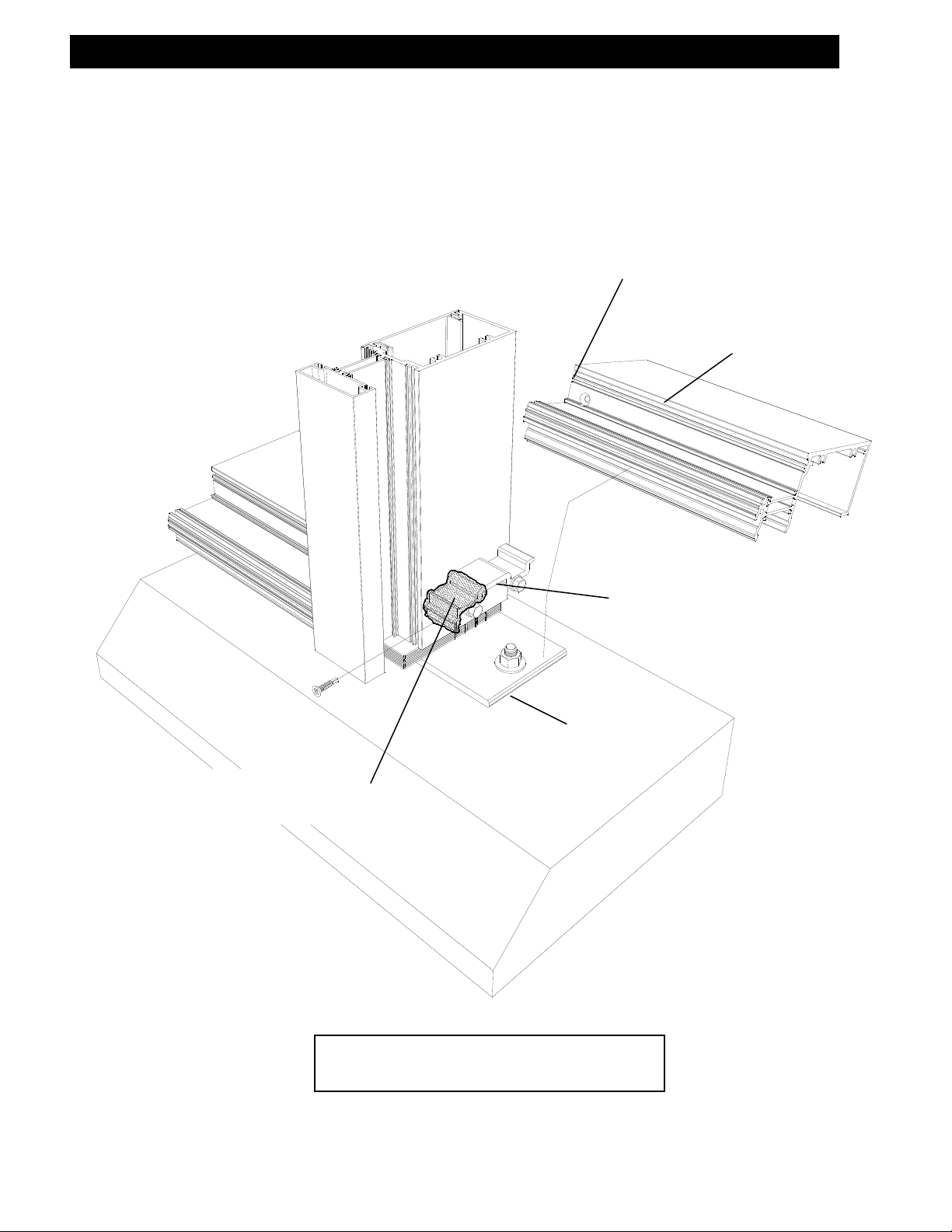
Under certain circumstances, it may be necessary to use drop-on
heads and sills with mullion ‘M’ and ‘F’ anchors. Refer to alternate
anchorage methods section for more information.
Apply sealant to the ends of the
sill as shown in the Standard
Installation Instructions
DROP-ON SILL
Apply sealant to the face of
the shear blocks as shown.
SHEAR BLOCK
‘M’ ANCHOR
SILL CONDITION WITH ‘M’ ANCHOR AND
DROP-ON HORIZONTALS
EFCO CORPORATION 6/2012 PART NO. Y557
5
Page 6
Series 5500 Advanced & Alternate Installation Instructions
Section II: Frame Unit Assembly & Frame Sealing
(Shear Block)
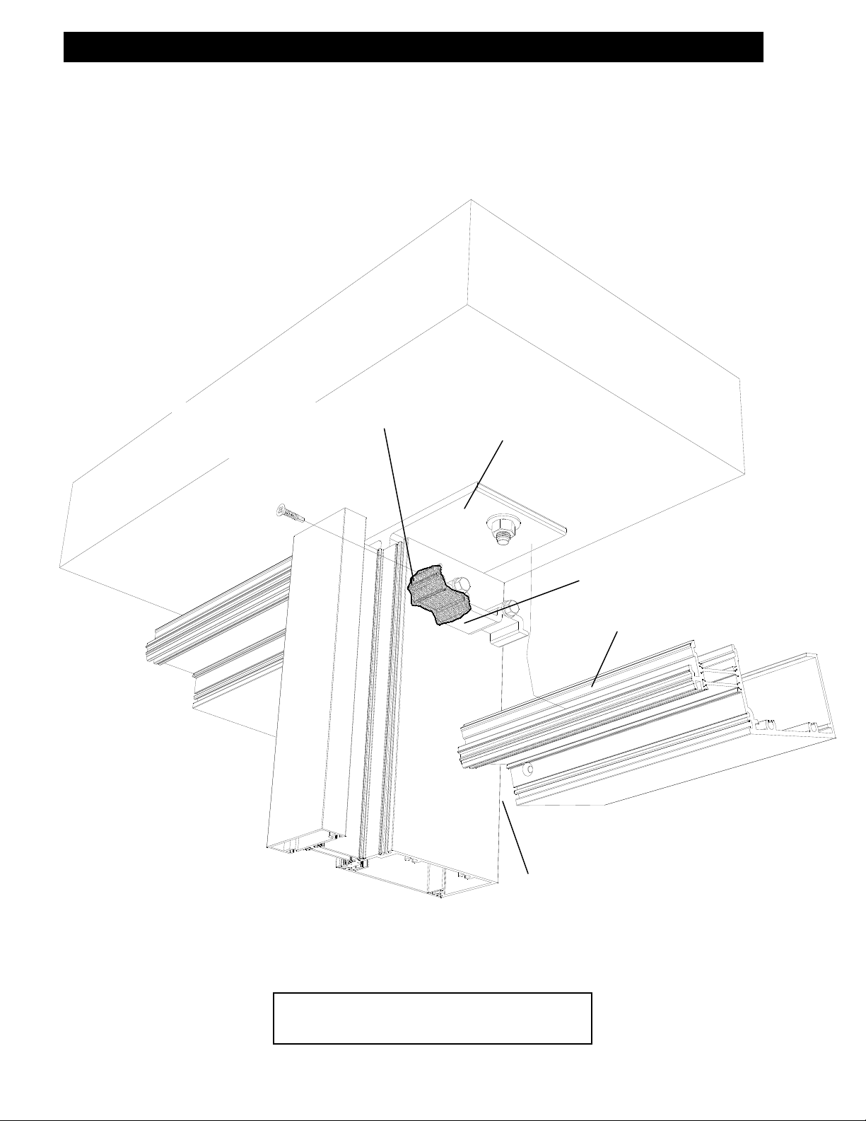
Apply sealant to the face of
the shear blocks as shown.
‘M’ ANCHOR
SHEAR BLOCK
DROP-ON HEAD
Apply sealant to the ends of the
sill as shown in the Standard
Installation Instructions
HEAD CONDITION WITH ‘M’ ANCHOR
AND DROP-ON HORIZONTALS
EFCO CORPORATION 6/2012 PART NO. Y557
6
Page 7
Series 5500 Advanced & Alternate Installation Instructions
Section III: Alternate Head Anchorage Method
(Sleeve Anchors)
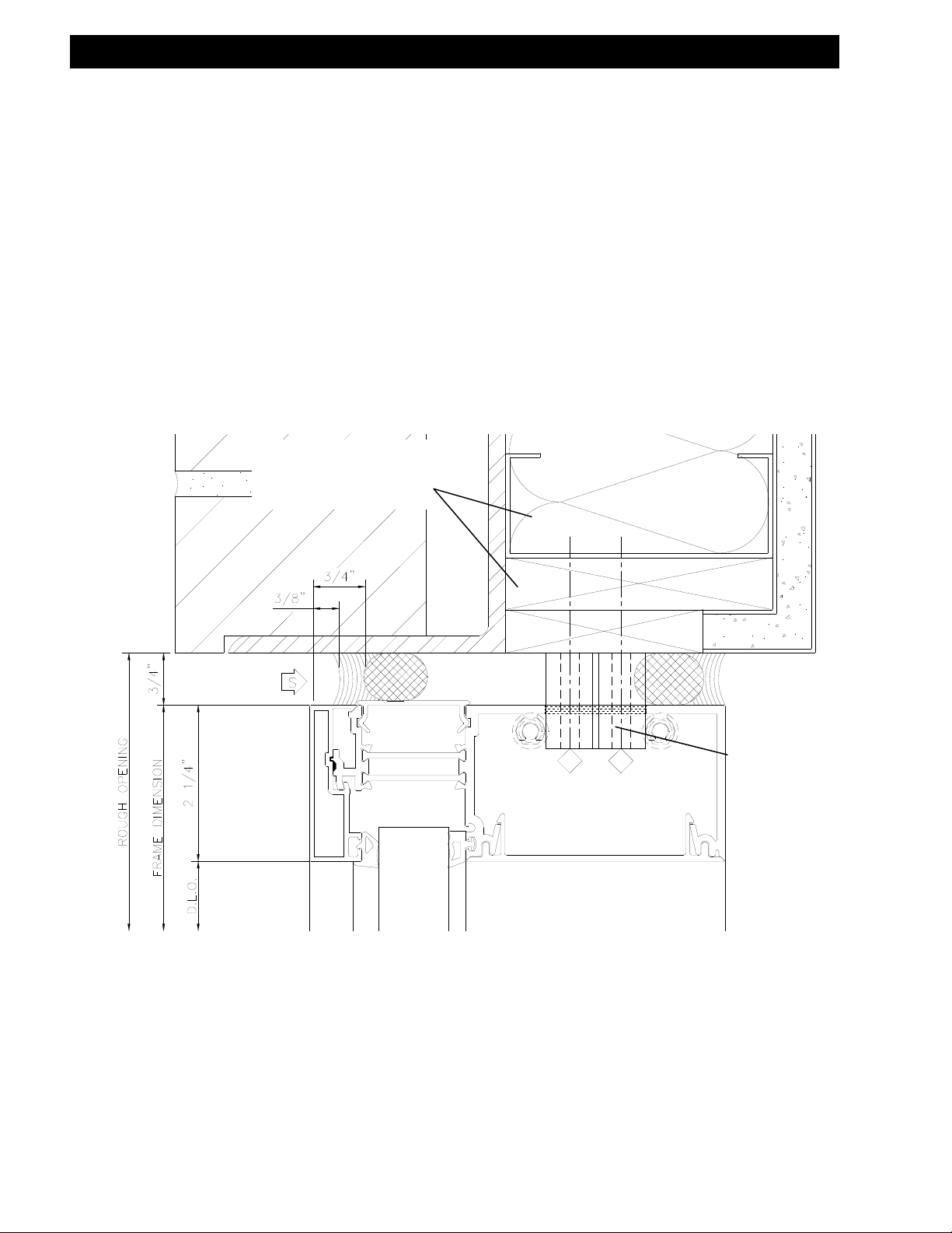
STEP #1 (Outside Glazed) INSTALL FRAME COMPONENTS
A. Refer to the approved shop drawings for job specific conditions, anchor type, anchor
bolt sizes, and locations. Install assemblies according to the approved shop drawings.
The anchor type used must be selected based on the structural requirements and the
substrate.
B. Follow steps 2 through 5 in Section III of the
complete the installation.
C. Refer to Sections IV and V of the
Preparation and Glazing Installation.
Standard Installation Instructions for Glazing
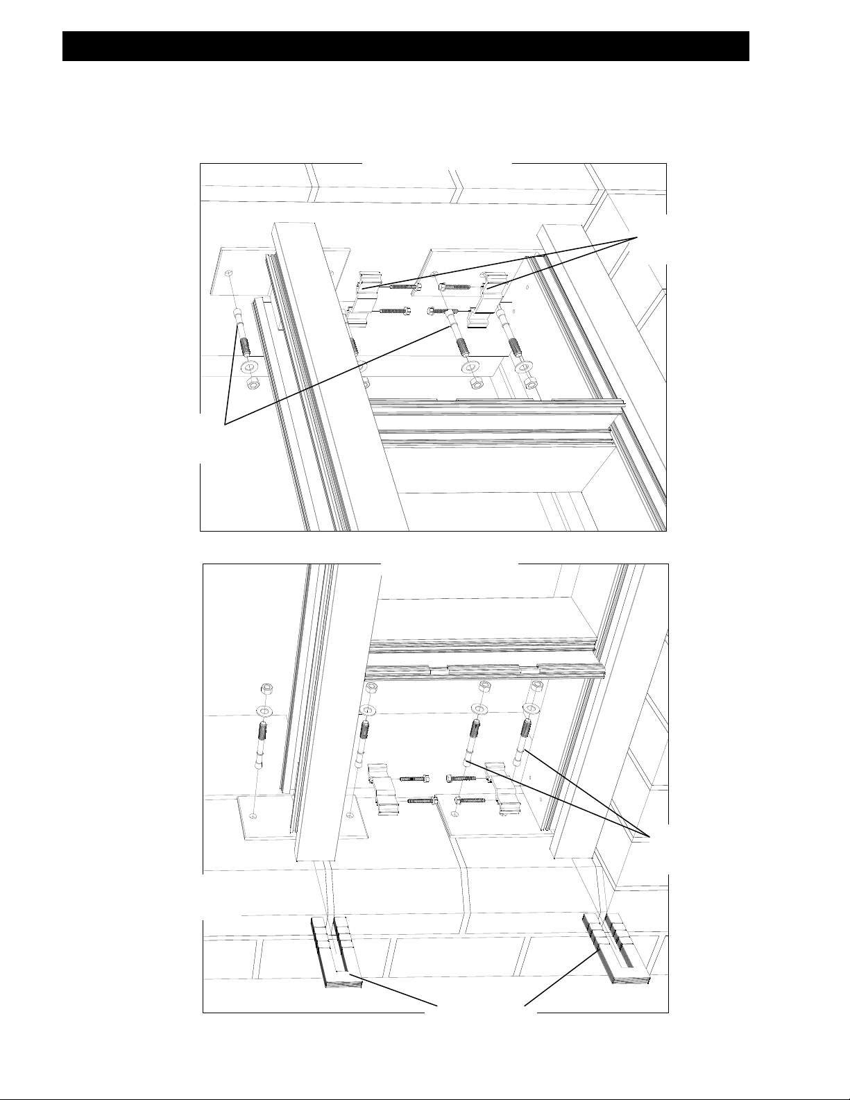
ANCHORAGE DETAIL FOR HEAD CONDITIONS
ATTACHING TO WOOD OR LIGHT GAUGE METAL STUDS
LIGHT GAUGE
METAL STUDS OR
WOOD SUBSTRATE
Standard Installation Instructions to
Note: It is up to the responsible engineer to determine
the structural adequacy and type of anchorage method
to be used for a given substrate, applied loads, and
building movements. The S-5500 has different
anchorage options available to meet these conditions.
EFCO CORPORATION 6/2012 PART NO. Y557
ANCHOR BOLTS AND
SLEEVE (Type and
quantity as required by
conditions and loads.
See Shop Drawings.)
7
Page 8
Series 5500 Advanced & Alternate Installation Instructions
Section III: Alternate Head Anchorage Method
(Sleeve Anchors)
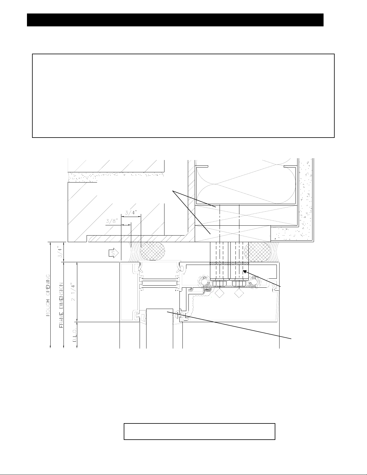
STEP #1 (Inside Glazed) INSTALL FRAME COMPONENTS
A. Refer to the approved shop drawings for job specific conditions, anchor type, anchor
bolt sizes, and locations. Install assemblies according to the approved shop drawings.
The anchor type used must be selected based on the structural requirements and the
substrate.
B. Follow steps 2 through 5 in Section III of the
complete the installation.
C. Refer to Sections IV and V of the
Preparation and Glazing Installation.
ANCHORAGE DETAIL FOR HEAD CONDITIONS
ATTACHING TO WOOD OR LIGHT GAUGE METAL STUDS.
LIGHT GAUGE METAL
STUDS OR WOOD
SUBSTRATE
Standard Installation Instructions for Glazing
Standard Installation Instructions to
Note: The glass size formula
for Inside Glazed S-5500 is
vertical D.L.O. plus 7/8” and
horizontal D.L.O. plus 1”.
Note: It is up to the responsible engineer to determine
the structural adequacy and type of anchorage method
to be used for a given substrate, applied loads, and
building movements. The S-5500 has different
anchorage options available to meet these conditions.
ALTERNATE HEAD ANCHORAGE
ANCHOR BOLTS AND
SLEEVE (Type and
quantity as required by
conditions and loads.
See Shop Drawings.)
Note: Glass bite at
this location for
Inside Glazed S-5500
is D.L.O. plus 3/8”.
(All Inside Glazed S5500 head
horizontals.)
EFCO CORPORATION 6/2012 PART NO. Y557
8
Page 9
Series 5500 Advanced & Alternate Installation Instructions
Section III: Alternate Head Anchorage Method
(Sleeve Anchors)
ANCHOR BOLTS AND
SLEEVES (Type and
quantity as required
by condition. See
Shop Drawings)
ALTERNATE HEAD ANCHORAGE
EFCO CORPORATION 6/2012 PART NO. Y557
HEAD FILLERS
9
Page 10

Series 5500 Advanced & Alternate Installation Instructions
Section III: Alternate Head Anchorage Method
(Sleeve Anchors)
ANCHOR BOLTS AND
SLEEVES (Type and
quantity as required by
conditions and loads.
See Shop Drawings.)
Head members with
notches as required,
allowing for lateral
building movements.
ALTERNATE HEAD ANCHORAGE
EFCO CORPORATION 6/2012 PART NO. Y557
10
Page 11
Series 5500 Advanced & Alternate Installation Instructions
Section III: Alternate Anchorage Method
(Heavy-Duty Anchor Connections)
Note: It is up to the responsible engineer to determine the structural
adequacy and type of anchorage method to be used for a given
substrate, applied loads, and building movements. The S-5500 has
different anchorage options available to meet these conditions.
‘M’ AND ‘F’
ANCHORS
SHEAR BLOCK
ANCHOR BOLTS (Type
and quantity as
required by conditions
and loads. See Shop
Drawings.)
SHEAR BLOCK
Shim as required at
anchors
each vertical mullion.
(Shim under setting
blocks at heavy lites.)
‘M’ AND ‘F’
ANCHORS
and
under
DROP-ON HEAD AND SILL
WITH ‘M’ AND ‘F’ ANCHORS
EFCO CORPORATION 6/2012 PART NO. Y557
11
Page 12
Series 5500 Advanced & Alternate Installation Instructions
Section III: Alternate Anchorage Method
(Heavy-Duty Anchor Connections)
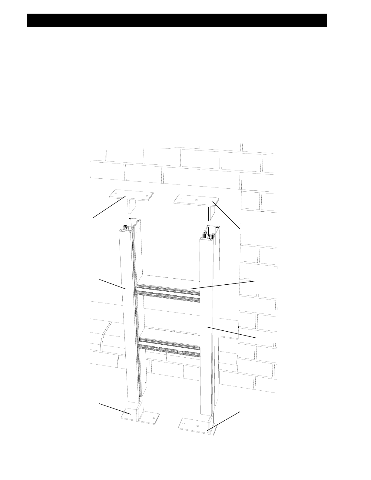
STEP #1 ASSEMBLE OUTSIDE GLAZED FRAME MEMBERS
This method of anchorage is available for conditions where the standard head and sill anchors or
alternate head anchors are not adequate for the given design criteria. Please consult with the structural
engineer responsible for the shop drawings for your project.
A. Assemble verticals and intermediate horizontals following the frame assembly and sealing
instructions in Section II. Shear blocks should be installed after the frames are set and
anchored to avoid interference with the anchor bolts.
B. Insert ‘F’ anchors into each end of the jamb mullion and ‘M’ anchors into each end of the
intermediate vertical.
‘M’ ANCHOR
INTERMEDIATE
VERTICAL
‘F’ ANCHOR
PRE-ASSEMBLED
FRAME UNIT
JAMB MULLION
‘M’ ANCHOR
EFCO CORPORATION 6/2012 PART NO. Y557
‘F’ ANCHOR
12
Page 13
Series 5500 Advanced & Alternate Installation Instructions
Section III: Alternate Anchorage Method
(Heavy-Duty Anchor Connections)
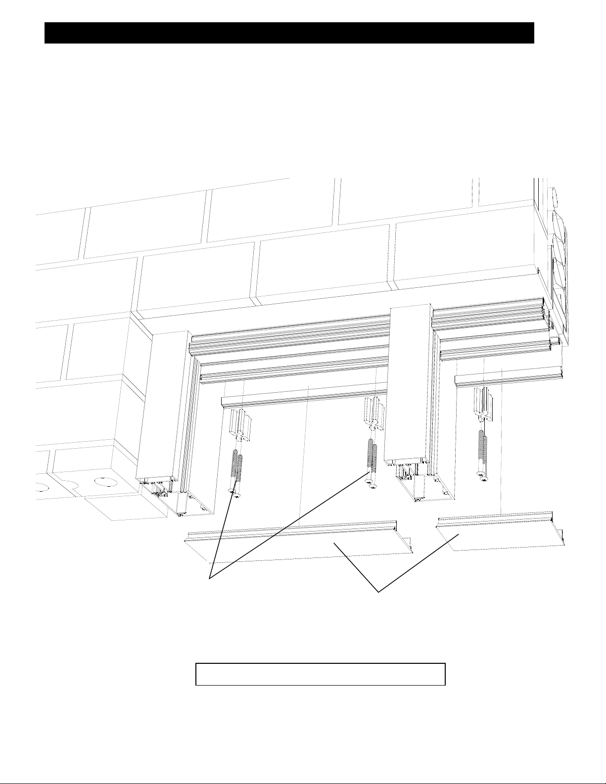
STEP #2 INSTALL FRAME COMPONENTS
A. Set the frame with ‘F’ and ‘M’ anchors into the opening. Adjust the frame’s position to place it
in the proper position with regard to established benchmarks.
B. Using dead load shims under each vertical mullion, level the frame and set it to the appropriate
elevation as indicated in the approved shop drawings.
C. After the frame is plumb and all adjustments have been made, match drill through the holes in
the ‘F’ and ‘M’ anchors into the surrounding substrate, and apply the appropriate anchor bolts.
Anchor bolt size, type, quantity, and location vary. Refer to the approved shop drawings for
more information. Anchor bolts should be installed per the recommendations of the bolt
manufacturer.
D. Apply the shear blocks to the top and bottom of the mullions as shown in the approved shop
drawings.
‘M’ ANCHOR
‘F’ ANCHOR
SHEAR BLOCKS FOR
DROP-ON HEAD
ANCHOR BOLTS
AS REQ’D.
SHEAR BLOCKS FOR
DROP ON SILL
‘M’ ANCHOR
PRE-ASSEMBLED
FRAME UNIT
ANCHOR BOLTS
AS REQ’D.
‘F’ ANCHOR
EFCO CORPORATION 6/2012 PART NO. Y557
DEAD LOAD
SHIMS
13
Page 14
Series 5500 Advanced & Alternate Installation Instructions
Section III: Alternate Anchorage Method
(Heavy-Duty Anchor Connections)
HEAD ANCHOR
ANCHOR BOLTS
AS REQ’D.
SHEAR BLOCKS FOR
DROP-ON HEAD
SHEAR BLOCKS FOR
DROP-ON SILL
SILL ANCHOR
ANCHOR BOLTS
AS REQ’D.
DEAD LOAD
SHIMS
EFCO CORPORATION 6/2012 PART NO. Y557
14
Page 15

Series 5500 Advanced & Alternate Installation Instructions
Section III: Alternate Anchorage Method
(Heavy-Duty Anchor Connections)
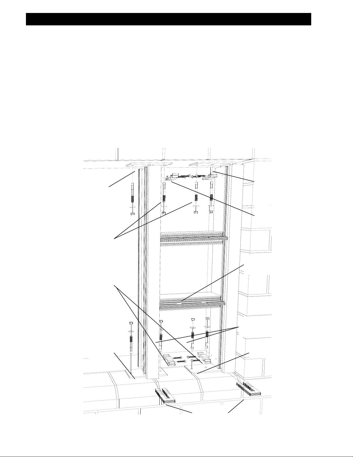
STEP #3 INSTALL FRAME COMPONENTS
A. From pages 12, 13, and 14, repeat steps 1 and 2. Set each successive frame into the
opening, snapping the verticals and fillers at each frame-until all frames are installed up
to the last frame at the opposite jamb.
B. Check frequently to ensure the installed framing is in the proper position with regard to
established benchmarks.
‘M’ ANCHOR
‘M’ ANCHOR
NOTE: On long runs, check overall frame dimensions at every fifth opening to avoid
dimensional build-up. The commercial cut length tolerance is +/- 1/16”. It is critical
to check every fifth unit for location relative to established benchmarks.
See Section III of the
Standard Installation
Instructions for special
sealant note at horizontals.
EFCO CORPORATION 6/2012 PART NO. Y557
15
Page 16

Series 5500 Advanced & Alternate Installation Instructions
Section III: Alternate Anchorage Method
(Heavy-Duty Anchor Connections)
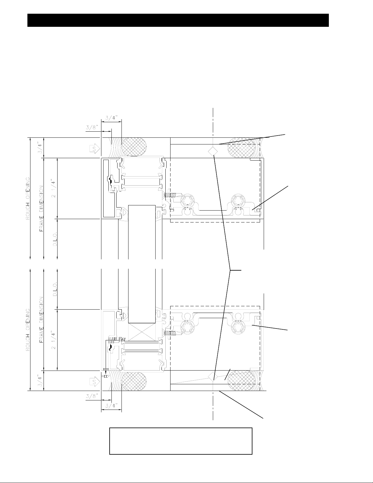
STEP #4 INSTALL FRAME HEAD & SILL COMPONENTS
A. Set the last frame in the run into the opening, mating the filler with the intermediate
vertical until the filler and vertical snap together.
B. When the frame is set level and plumb, apply dead load shims below the verticals, and
apply anchor bolts as shown per the approved shop drawings.
ANCHOR BOLTS
AS REQ’D.
‘F’ ANCHOR
ANCHOR BOLTS
AS REQ’D.
See Section III of the Standard
Installation Instructions , step 4 for
special sealant note at horizontals.
IMPORTANT NOTE:
It is critical to allow at least a ¾” space between the perimeter of the jamb mullion and
the condition for setting space for the last frame unit to be installed.
PRE-ASSEMBLED
FRAME UNIT
‘F’ ANCHOR
DEAD LOAD
SHIMS
EFCO CORPORATION 6/2012 PART NO. Y557
16
Page 17

Series 5500 Advanced & Alternate Installation Instructions
Section III: Alternate Anchorage Method
(Heavy-Duty Anchor Connections)
STEP #5 INSTALL FRAME HEAD & SILL COMPONENTS
A. Drop-on and attach head and sill horizontals as indicated in the approved shop
drawings. Be certain to properly hook the horizontal onto the shear block.
B. Section II of the
notes.
C. Refer to Sections IV and V for Glazing Preparation and Glazing Installation.
Standard Installation Instructions for special sealant and assembly
HEAD
SILL
EFCO CORPORATION 6/2012 PART NO. Y557
17
Page 18

Series 5500 Advanced & Alternate Installation Instructions
Section V: PUNCHED OPENING & RIBBON WINDOWS
(Frame Opening & Frame Sealing)
STEP #1 ASSEMBLE OUTSIDE GLAZED FRAME MEMBERS
A. Seal the ends of the vertical mullions at the exterior and snap-in the PVC fillers. (Section II of
the
Standard Installation Instructions).
B. The base section of the two-part anchor must be slid into the heads and sills prior to
assembling the frames. The remaining part of the anchor can be applied in the field.
C. Sealant must be applied to the ends of each horizontal member before assembly. (See
enlargement Section II of the
D. Assemble the frames per the approved shop drawings.
Standard Installation Instructions.)
PVC FILLER
VERTICAL FILLER
FRAME ASSEMBLY SCREWS ¼” –
14 X 1 ½” HWSMS 18-8 Typical
CUSTOM TWO-PART
EXTRUDED
ALUMINUM ANCHORS
HEAD
VERTICAL FILLER
INTERMEDIATE VERTICAL
INTERM.
HORIZ’S.
PERIMETER
MULLION
CUSTOM TWO-PART
EXTRUDED
ALUMINUM ANCHORS
PVC FILLER
PUNCHED OPENING AND RIBBON WINDOWS
EFCO CORPORATION 6/2012 PART NO. Y557
SILL
18
Page 19

Series 5500 Advanced & Alternate Installation Instructions
Section V: PUNCHED OPENING & RIBBON WINDOWS
(Frame Opening & Frame Sealing)
Punched opening and ribbon window elevations are typically used for small openings or openings of
limited height where the frames can be partially assembled off-site, moved to the jobsite, and then
groups of frames are snapped together. This allows groups of frames to be set into the opening all at
one time. Custom extruded aluminum anchors are slid into the heads and sills during frame assembly.
This method of anchorage is limited due to certain structural limitations. Please consult with the
structural engineer responsible for the shop drawings for your project. This type of installation also
requires that there be no obstructions (such as floor slabs or columns) that prevent the frames from
being installed from the interior.
SHIMS AT
ANCHOR
ANCHOR BOLTS
AS REQ’D.
CUSTOM TWO-PART
EXTRUDED
ALUMINUM ANCHORS
Note: It is up to the responsible
engineer to determine the
structural adequacy and type of
anchorage method to be used
for a given substrate, applied
loads, and building movements.
The S-5500 has different
anchorage options available to
meet these conditions.
SHIMS AT
ANCHOR
PUNCHED OPENING AND RIBBON WINDOWS
EFCO CORPORATION 6/2012 PART NO. Y557
DEAD LOAD
SHIM AT
VERTICAL
ANCHOR BOLTS
AS REQ’D.
19
Page 20

Series 5500 Advanced & Alternate Installation Instructions
Section V: PUNCHED OPENING & RIBBON WINDOWS
(Frame Opening & Frame Sealing)
STEP #1 SIDE STACK PRE-ASSEMBLED FRAMES
Frames can be partially assembled off-site and moved to the jobsite. Then, groups of frames may be
snapped together, allowing them to be set into the opening at one time. The size of the group of
frames to be installed is limited by the field’s handling capacity due to the weight and size of the
assemblies.
PRE-ASSEMBLED
FRAMES
See Section III of the Standard
Installation Instructions , step 4 for
special sealant note at horizontals.
EFCO CORPORATION 6/2012 PART NO. Y557
20
Page 21

Series 5500 Advanced & Alternate Installation Instructions
Section V: PUNCHED OPENING & RIBBON WINDOWS
(Alternate Anchorage Method)
STEP #2 PREPARE TO SET FRAMES
A. Slide the anchor plates into the base anchors that were installed during frame assembly.
B. Refer to the approved shop drawings to review anchor placement, type, and conditions.
CUSTOM TWO-PART
EXTRUDED
ALUMINUM ANCHORS
ASSEMBLED GROUP
OF FRAMES
EFCO CORPORATION 6/2012 PART NO. Y557
21
Page 22

Series 5500 Advanced & Alternate Installation Instructions
Section V: PUNCHED OPENING & RIBBON WINDOWS
(Alternate Anchorage Method)
STEP #3 SET GROUPS OF FRAMES
A. Set the assembled groups of frames into the opening.
B. Using dead load shims under each vertical mullion, level the frame and set it to the
appropriate elevation as indicated in the approved shop drawings.
C. Use shims between the anchor plate and the condition to set the frame the proper
distance to the face of the building. After the frames are plumb and the frames have
been properly installed relative to established benchmarks, match drill through the
holes in the anchor plates into the surrounding substrate, and apply the appropriate
anchor bolts. Anchor bolt size, type, quantity, and location vary. Refer to the approved
shop drawings for more information. Anchor bolts should be installed per the
recommendations of the bolt manufacturer.
ADJUSTMENT
OPENING IN BUILDING
STRUCTURE
SHIMS
DEAD LOAD
SHIMS
EFCO CORPORATION 6/2012 PART NO. Y557
ASSEMBLED
GROUP OF
FRAMES
DEAD LOAD
SHIMS
ANCHOR BOLTS
AS REQ’D.
22
Page 23

Series 5500 Advanced & Alternate Installation Instructions
Section V: PUNCHED OPENING & RIBBON WINDOWS
(Alternate Anchorage Method)
Refer to Sections IV and V for Glazing Preparation and Glazing Installation.
EFCO CORPORATION 6/2012 PART NO. Y557
23
Page 24

Series 5500 Advanced & Alternate Installation Instructions
Section V: Vertical Splice Joints
STEP #1 LOCATE SPLICE JOINTS
A. Splice joints should occur at spandrel areas (if possible). Refer to the approved shop
drawings for actual locations.
B. Depending on job requirements, the mullion splice may be shop or field assembled in
the top of the lower mullion. The cover splice is attached to the bottom of the upper
mullion. Where head clearance is insufficient to allow the top mullion to be lifted over
the splice sleeves, retractable splices should be used. The splices are to be taped into
the bottom of the top mullion and dropped down to the stop screw in the mullion
below.
C. GENERAL NOTE: The following pages depict a splice joint of 1/2”. This will allow plus
or minus 1/4” of movement for each splice location. Thermal expansion and live
deflection requirements should be considered when determining the location and
quantities of splice joints. If the total amount of movement cannot be accommodated
locating splices at every other floor or alternatively at each floor, expansion
horizontals or some alternative method should be used. Contact EFCO for further
evaluation.
D. Refer to this section for pressure cover splice locations, mullion splice locations, and
sealing instructions.
E. Once a final check of expansion joint placement and mullion position is made, the final
match drilling of mullion through anchor holes may be completed.
BACKER
ROD
JAMB INTERMEDIATE EXPANSION MULLION
Mullion splice sleeves
with bond breaker tape.
SPLICE SLEEVE
STOP SCREWS
PLAN VIEW – MULLION SPLICE
EFCO CORPORATION 6/2012 PART NO. Y557
¼” X 1” X 5” FOAM
CAULK JOINT BACKER
Cover splice sleeves
with bond breaker
tape.
24
Page 25

Series 5500 Advanced & Alternate Installation Instructions
MULLION LENGTH
Section V: Vertical Splice Joints
MULLION
SPLICE
5/8"(MIN.)
COVER LENGTHCOVER LENGTH
1/2"
MULLION SECTION LENGTH
GLAZING ADAPTER AND REAR
1/2"
5 1/2"
3 " NOTCH
1/2"
MULLION LENGTH
COVER
SPLICE
2"
3 " NOTCH
SPLICE SLEEVE
STOP SCREW
MULLION SECTION LENGTH
GLAZING ADAPTER AND REAR
NOTE: All anchors must be fixed before glazing begins.
SIDE VIEW – MULLION SPLICE
EFCO CORPORATION 6/2012 PART NO. Y557
25
Page 26

Series 5500 Advanced & Alternate Installation Instructions
Section V: Vertical Splice Joints
STEP #2 ATTACH MULLION SPLICE SLEEVES
A. Clean all surfaces that will contact sealant per the sealant manufacturer’s instructions,
making sure to remove all oils and debris from contact surfaces.
B. Apply bond breaker tape to the mullion splice sleeve.
C. For standard installation, attach the mullion splice sleeve to the top of the lower mullion
with splice sleeve attachment screws. Cap seal the fastener heads.
MULLION SPLICE SLEEVE
BOND BREAKER TAPE
1/4” X 1” X 5”
FOAM CAULK
JOINT BACKER
SPLICE ATTACHMENT
SCREWS (cap seal)
LOWER MULLION
EFCO CORPORATION 6/2012 PART NO. Y557
SPLICE STOP SCREW
(When required) See
STEP 1, item B, , page 24.
26
Page 27

Series 5500 Advanced & Alternate Installation Instructions
Section V: Vertical Splice Joints
STEP #3 CRITICAL MULLION SEAL AT SPLICE
A. Insert the 1/4” x 1” x 5” long foam caulk joint backer as shown below leaving 1” of
the backer extending above the top of the mullion.
B. Apply sealant between the thermal struts, starting where the notch in the mullion
begins at the exterior cover, sealing the space to the top of the mullion as shown.
C. Tool the sealant flush with the face of the notch of the thermal struts.
MULLION SPLICE SLEEVE
1/4” X 1” X 5”
FOAM CAULK
JOINT BACKER
Seal the gap between the
thermal struts including
the void at the bottom of
the notch.
SPLICE ATTACHMENT
SCREWS (cap seal)
LOWER MULLION
EFCO CORPORATION 6/2012 PART NO. Y557
27
Page 28

Series 5500 Advanced & Alternate Installation Instructions
Section V: Vertical Splice Joints
STEP #4 ATTACH MULLION COVER SPLICE SLEEVES
A. Apply bond breaker tape to the mullion cover splice sleeve.
B. For standard installation, attach the mullion cover splice sleeve to the bottom of the
upper mullion with splice sleeve attachment screws. Cap seal the fastener heads.
UPPER MULLION
BOND BREAKER
TAPE
EFCO CORPORATION 6/2012 PART NO. Y557
SPLICE ATTACHMENT
SCREWS (cap seal)
MULLION COVER
SPLICE SLEEVE
28
Page 29

Series 5500 Advanced & Alternate Installation Instructions
Section V: Vertical Splice Joints
STEP #5 ALIGN AND STACK ASSEMBLED FRAMES
A. Align the pre-assembled frames and stack together at the splice joints.
B. Ensure the 1/4” x 1” x 5” long foam caulk joint backer is inserted into the gap
between the thermal struts in the upper mullion as noted below.
C. Position the mullions to the appropriate elevation with regard to established
benchmarks, and shim or fix the mullions at their respective dead load anchor
points.
D. Snap-in both of the adjacent frames before sealing the mullion splice joints.
E. Clean the splice sealant-contact areas per sealant manufacturer’s
recommendations.
F. Apply backer rod between the mullions, adapters, and splice to back-up the joint,
seal the joint and tool as shown on page 30.
ADJACENT FRAME
ASSEMBLIES
joint backer between
UPPER FRAME
ASSEMBLY
MULLION
SPLICE SLEEVES
Insert foam caulk
thermal struts.
LOWER FRAME
ASSEMBLY
EFCO CORPORATION 6/2012 PART NO. Y557
29
Page 30

Series 5500 Advanced & Alternate Installation Instructions
Section V: Vertical Splice Joints
STEP #6 SEAL MULLION SPLICE
A. Install backer rod to back-up the sealant at the mullion joints as shown on page 24.
B. Apply sealant into the mullion splice joint and tool the joint. Do not obstruct the
glazing reglets.
C. Apply sealant into the pressure cover splice joint and tool the joint. Do not obstruct
the glazing reglets.
D. Apply sealant around the 1/4” x 1” x 5” long foam caulk joint backer. Tool the joint
and blend the sealant into the mullion splice joint and over the thermal struts. A
minimum of 1/4” sealant surface contact with bonding surfaces is required.
E. Apply sealant into the joint between the notched thermal struts and the back of the
notched pressure cover and tool the joint smooth (see page 31.)
B. Apply sealant into
the mullion joint and
tool smooth.
D. Apply sealant
around the 1/4” x 1”
x 5” foam caulk joint
backer, tool smooth.
A. Install backer rod at the
mullion joint to back-up
the sealant.
E. Apply sealant into the
joint between the notched
thermal struts and the
back of the notched
pressure cover, and tool
the joint smooth.
(See page 31.)
C. Apply sealant into
the pressure cover joint
and tool smooth.
Note: Gasket and adapter
reglets on both sides of the
glazing pocket must be free of
sealant obstructions before
placing gaskets and adapters.
EFCO CORPORATION 6/2012 PART NO. Y557
30
Page 31

Series 5500 Advanced & Alternate Installation Instructions
Section V: Vertical Splice Joints
Apply sealant into the joint between
the notched thermal struts and the
back of the notched pressure cover,
and tool the joint smooth. The joint
should have an hourglass shape and a
maximum width of 5/16” at the
thinnest part of the joint.
SPLICE JOINT DETAIL
EFCO CORPORATION 6/2012 PART NO. Y557
31
Page 32

Series 5500 Advanced & Alternate Installation Instructions
Section V: Vertical Splice Joints
STEP #7 INSTALL AND SEAL ADAPTERS
A. Seal gasket races continuously and snap-in adapters, if required.
B. Snap-in adapters, carefully using a small pry bar, if required.
C. Install backer rod to back-up sealant at the glazing adapters.
D. Apply sealant and tool into joints. Do not obstruct the glazing
reglets.
Seal gasket races prior
to snapping-in adapters.
Install backer rod at the
adapter joint to back-up
the sealant.
Apply sealant into the
adapter joint and tool
smooth.
EFCO CORPORATION 6/2012 PART NO. Y557
32
Page 33

Series 5500 Advanced & Alternate Installation Instructions
Section V: Vertical Splice Joints
STEP #8 INSTALL INTERIOR GASKETS, GLAZING, AND EXTERIOR GASKETS
A. Install the interior gaskets allowing them to span the mullion splice joint.
B. Set the glazing into the opening as previously instructed.
C. Apply the exterior vertical drive-in wedge gaskets into the vertical mullions as
shown in Section VI of the Standard Installation Instructions.
D. Apply the horizontal pressure covers and horizontal exterior drive-in wedge
gaskets at the top and bottom of the lite as shown in the Standard Installation
Instructions.
GLAZING ADAPTERS
(When required)
INTERIOR GASKETS
(Runs continuously
through splice joint)
GLAZING INFILL
EFCO CORPORATION 6/2012 PART NO. Y557
EXTERIOR GASKETS
(Runs continuously
through splice joint)
33
Page 34

Series 5500 Advanced & Alternate Installation Instructions
Section VI: Expansion Mullions
STEP #1 PREPARE EXPANSION MULLIONS
Expansion mullions are required for elevations wider than 20’-0”. The maximum spacing
between expansion mullions is 20’-0”. Refer to the approved shop drawings for specific
locations and more information.
A. Thread the finger gaskets into the reglets of the male half of the expansion
mullion for the full length of the mullion. Refer to the approved shop drawings for
part numbers.
B. Crimp the reglet at the finger gaskets about ½” from each end with a chisel or
similar tool to lock the gasket in place.
FINGER GASKET
GASKET REGLET
MALE EXPANSION
MULLION
FINGER GASKET
EFCO CORPORATION 6/2012 PART NO. Y557
34
Page 35

Series 5500 Advanced & Alternate Installation Instructions
Section VI: Expansion Mullions
STEP #1 (Continued) PREPARE EXPANSION MULLIONS
When vertical D.L.O.s exceed 48”, mullion clips may be required at the center of the lite.
Contact EFCO or refer to the approved shop drawings for more information.
A. Slide the mullion clips into the grooves of the mullion as shown below.
B. Crimp the legs at each end of the mullion clip with a punch or similar tool to lock it in
place. Refer to the approved shop drawings for more information.
Crimp legs at
top and bottom
of mullion clip.
FEMALE EXPANSION
MULLION
MULLION CLIP X
4” LONG
EFCO CORPORATION 6/2012 PART NO. Y557
35
Page 36

Series 5500 Advanced & Alternate Installation Instructions
Section VI: Expansion Mullions
STEP #2 STACK EXPANSION MULLIONS
A. Apply a continuous bead of sealant to the male mullion half as noted below.
B. After the frames are assembled as instructed in Section II, install the frames using the
anchor methods required. Stack the expansion mullions together using ‘C’ clamps to
press each half of the mullion together. Use shims as shown below to prevent from
closing the expansion mullion. Remove the shims after the anchors are set.
C. Tool the sealant joint in the space between the expansion mullions as shown below.
This seal will marry with the joint plug seals when the joint plugs are applied.
SHIM
MALE MULLION
CONTINUOUS
SEALANT JOINT
1/8” notch on
male mullion side
of glazing pocket.
SHIM
EFCO CORPORATION 6/2012 PART NO. Y557
36
Page 37

Series 5500 Advanced & Alternate Installation Instructions
Section VI: Expansion Mullions
STEP #3 GLAZE EXPANSION MULLIONS
A. Glaze the curtain wall as instructed in Sections IV, V, and VI of the Standard
Installation Instructions.
IMPORTANT NOTE: The horizontal and horizontal pressure cover must be notched,
or cut 1/8” short on the male mullion side of the glazing pocket, as shown below to
allow for horizontal expansion and contraction of the curtain wall.
MALE MULLION
EFCO CORPORATION 6/2012 PART NO. Y557
Horizontal pressure
cover cut 1/8” short
on male mullion side.
37
Page 38

Series 5500 Advanced & Alternate Installation Instructions
Section VII: Glazing at Spandrel Areas of I.G. Frames
Note: S-5500 curtain wall must be outside glazed at the floor lines, some column locations, shear
walls and parapet areas, or any other area that would not allow the glazing infill to be inside set.
Refer to the approved shop drawings for locations and exact configuration of the spandrel areas. The
following is a guide for a typical floor line spandrel installation.
GLAZING SPANDREL AREAS AT FLOOR LINES
A. Vision lites will consist of inside glazed horizontals at the head of the lite as shown in
“FIGURE A” below.
B. The top of the spandrel lite and any intermediate horizontals within the spandrel areas will
consist of an outside glazed horizontal with a roll-on pressure cover as shown in “FIGURE B”
below.
C. The bottom of the spandrel lite above the vision area will consist of an inside/outside-glazed
horizontal with a roll-on pressure cover and removable interior bead as shown in “FIGURE
C” below. This will allow the spandrel lite to be outside set and the vision lite to be inside
set.
VISION AREAS
SPANDREL AREAS
SPLICE JOINT
FLOOR SLAB
FIGURE A
FIGURE B
VISION AREAS
SPANDREL AT FLOOR LINE
EFCO CORPORATION 6/2012 PART NO. Y557
FIGURE C
38
Page 39

Series 5500 Advanced & Alternate Installation Instructions
Section VII: Glazing at Spandrel Areas of I.G. Frames
STEP #1 GLAZE ADJACENT VISION AREAS
A. Apply the setting blocks at the bottom of the vision lites above and below the
spandrel areas per the approved shop drawings.
B. Install the preset glazing gaskets on the exterior side of the glazing pocket at the
vision areas per “Glazing Preparation” in Section IV of the Standard Installation
Instructions.
C. Set the glazing infill and anti-walk blocks into the vision areas as instructed per
“Glazing Installation” in Section V of the Standard Installation Instructions.
D. Apply the interior glazing beads and drive-in wedge glazing gaskets per “Interior
Drive-In Gasket & Glazing Bead Installation” in Section VI of the Standard Installation
Instructions.
SPANDREL AREAS
SPLICE JOINT
VISION AREAS
FLOOR SLAB
INTERIOR VIEW
EFCO CORPORATION 6/2012 PART NO. Y557
VISION AREAS
39
Page 40

Series 5500 Advanced & Alternate Installation Instructions
Section VII: Glazing at Spandrel Areas of I.G. Frames
STEP #2 INSTALL SETTING BLOCKS AND PRESET GASKETS INTO MULLIONS
A. Apply the setting blocks at the bottom of the spandrel lites per the approved shop
drawings.
B. Install the preset glazing gaskets per “Glazing Preparation” in Section IV of the
Standard Installation Instructions, except the gaskets will be set on the
of the glazing pocket as shown below.
VISION AREAS
interior
side
SPANDREL AREAS
SPLICE JOINT
FLOOR SLAB
EXTERIOR VIEW
VISION AREAS
EFCO CORPORATION 6/2012 PART NO. Y557
40
Page 41

Series 5500 Advanced & Alternate Installation Instructions
Section VIII: Captured Glazing Adaptor Installation
STEP #1 INSTALL GLAZING ADAPTERS
A. Prior to installing the glazing adapters, seal the full length of the gasket raceway
with sealant.
B. Snap the glazing adapters in place into the sealant starting with the verticals.
Allow at least 1/8” clearance from the bottom of the glazing adapters to the top of
the joint plugs to allow for weepage.
C. Apply sealant to the ends of the horizontal adapters prior to setting them into
position. Snap the horizontal adapters in place between the vertical adapters. Seal
the face of the adaptor intersections with sealant. Tool all sealant joints and
remove all excess sealant.
Continuously seal the
gasket raceway with
sealant prior to
installing the adapters.
NOTE: The vertical adapters
will need clearance above
the joint plugs, free from
sealant for weepage.
EFCO CORPORATION 6/2012 PART NO. Y557
GLAZING ADAPTERS
Glazing adapter cut formula:
Vertical = D.L.O. + 1”
Horizontal = D.L.O. – 1/16”
41
Page 42

Series 5500 Advanced & Alternate Installation Instructions
Section VIII: SSG Glazing Adaptor Installation
STEP #1 INSTALL GLAZING ADAPTERS IF REQUIRED
A. Prior to installing the glazing adapters, seal the full length of the gasket raceway
with sealant.
B. Snap or screw apply the glazing adapters in place into the sealant, starting with
the verticals. Allow at least 1/8” clearance from the bottom of the glazing
adapters to the top surface of the glazing pocket at captured horizontals to allow
for weepage.
C. Apply sealant to the ends of the horizontal adapters prior to setting them into
position. Snap or screw apply the horizontal adapters in place between the vertical
adapters. Seal the face of the adapter intersections with sealant. Seal all screw
heads with sealant. Tool all sealant joints, and remove all excess sealant.
SCREW APPLIED
GLAZING
ADAPTERS
Continuously seal the
gasket raceway with
sealant prior to
installing the adapters.
GLAZING ADAPTERS
STANDARD SSG JAMB WITH REVEAL AND
CAPTURED INTERMEDIATE HORIZONTAL
Seal and tool the sealant at the
ends of the adapters at the
intersection of the verticals.
NOTE: The vertical adapters
will need clearance above
the joint plugs, free from
sealant, for weepage.
NOTE: Refer to the approved
shop drawings for screw
types, adapter part numbers,
and glazing combinations.
STANDARD
SSG JAMB
CAPTURED
HORIZONTAL
EFCO CORPORATION 6/2012 PART NO. Y557
GLAZING ADAPTERS
42
Page 43

Series 5500 Advanced & Alternate Installation Instructions
Section VIII: SSG Glazing Adaptor Installation
STEP #1 INSTALL GLAZING ADAPTERS (CONTINUED)
Continuously seal the
gasket raceway with
sealant prior to
installing the adapters.
SCREW APPLIED
GLAZING
ADAPTERS
NOTE: Refer to the approved
shop drawings for screw
types, adapter part numbers,
and glazing combinations.
Seal and tool the sealant at the
ends of the adapters at the
intersection of the verticals.
STANDARD
SSG JAMB
GLAZING ADAPTERS
EFCO CORPORATION 6/2012 PART NO. Y557
43
Page 44

Series 5500 Advanced & Alternate Installation Instructions
Section VIII: SSG Glazing Adaptor Installation
STEP #1 INSTALL GLAZING ADAPTERS (CONTINUED)
Continuously seal the
gasket raceway with
sealant prior to
installing the adapters.
SCREW APPLIED
GLAZING
ADAPTERS
GLAZING ADAPTERS
NOTE: Refer to the approved
shop drawings for screw
types, adapter part numbers,
and glazing combinations.
CAPTURED
HORIZONTALS
Seal and tool the sealant at the
ends of the adapters at the
intersection of the verticals.
SSG VERTICAL
MULLION
STANDARD SSG VERTICAL AND CAPTURED
INTERMEDIATE HORIZONTAL
EFCO CORPORATION 6/2012 PART NO. Y557
44
Page 45

Series 5500 Advanced & Alternate Installation Instructions
Section VIII: SSG Glazing Adaptor Installation
STEP #1 INSTALL GLAZING ADAPTERS (CONTINUED)
Continuously seal the
gasket raceway with
sealant prior to
SCREW APPLIED
GLAZING
ADAPTERS
installing the adapters.
NOTE: Refer to the approved
shop drawings for screw
types, adapter part numbers,
and glazing combinations.
Seal and tool the sealant at
the ends of the adapters at the
intersection of the verticals.
SSG EXPANSION
MULLION
SSG HORIZONTAL
MULLIONS
SSG INTERMEDIATE EXPANSION VERTICAL AND
SSG INTERMEDIATE HORIZONTAL
EFCO CORPORATION 6/2012 PART NO. Y557
45
Page 46

Series 5500 Advanced & Alternate Installation Instructions
Section VIII: SSG Glazing Adaptor Installation
STEP #1 INSTALL GLAZING ADAPTERS (CONTINUED)
SCREW APPLIED
GLAZING
ADAPTERS
Continuously seal the
gasket raceway with
sealant prior to
installing the adapters.
NOTE: Refer to the approved
shop drawings for screw
types, adapter part numbers,
and glazing combinations.
Seal and tool the sealant at
the ends of the adapters at the
intersection of the verticals.
SSG VERTICAL
MULLION
SSG HORIZONTAL
MULLIONS
SSG INTERMEDIATE VERTICAL AND
SSG INTERMEDIATE HORIZONTAL
EFCO CORPORATION 6/2012 PART NO. Y557
46
 Loading...