

Page 1

PT 2700 - PTX 2700
(1.86 cu.in)
en
fr
es
OPERATOR’S INSTRUCTION MANUAL
MANUEL D’UTILISATION ET D’ENTRETIEN
MANUAL DE INSTRUCCIONES
Page 2
en
INTRODUCTION
To correctly use the pole pruner and prevent accidents, do not start work without
having first carefully read this manual. You will find explanations concerning the
operation of the various parts plus instructions for necessary checks and relative
maintenance.
Note: Illustrations and specifications in this manual may vary according to Country
requirements and are subject to change without notice by the manufacturer.
THE OPERATOR’S MANUAL
Your operator’s manual is for your protection. READ IT. Keep it in a safe place for
reference. Know what you are doing before you begin assembly of the unit. Proper
preparation and upkeep go hand-in-hand with satisfactory performance of the pole
pruner and safety.
Contact your dealer or the distributor for your area if you do not understand any of the
instructions in this manual.
In addition to the operating instructions, this manual contain paragraphs that require
your special attention.
Such paragraphs are marked with the symbols described below:
Warning: where there is a risk of an accident or personal injury or serious damage to
property.
Caution: where there is a risk of damaging the machine or its individual components.
WARNING - To ensure safe and correct operation of the pole
pruner, this operator's manual should always be kept with or
near the machine. Do not lend or rent your pole pruner without
the operator's instruction manual.
WARNING: Allow only persons who understand this manual to
operate your pole pruner.
2
Page 3

TABLE OF CONTENTS
PRODUCT IDENTIFICATION
Pole pruner Components . . . . . . . . . . . . . . . . . . . . . . . . . . . . . . . . . . . . . . . . . . . . . . . . . . . . . . . 4
SAFETY
Understanding Safety Labels . . . . . . . . . . . . . . . . . . . . . . . . . . . . . . . . . . . . . . . . . . . . . . . . . . . . 5
State and Local Requirements . . . . . . . . . . . . . . . . . . . . . . . . . . . . . . . . . . . . . . . . . . . . . . . . . . . 5
SAFETY RULES
Basic Safety Precautions . . . . . . . . . . . . . . . . . . . . . . . . . . . . . . . . . . . . . . . . . . . . . . . . . . . . . . . 7
Fuel Handling . . . . . . . . . . . . . . . . . . . . . . . . . . . . . . . . . . . . . . . . . . . . . . . . . . . . . . . . . . . . . . . . 8
Operation and Safety . . . . . . . . . . . . . . . . . . . . . . . . . . . . . . . . . . . . . . . . . . . . . . . . . . . . . . . . . . 8
Precautions to Reduce Vibration Risk . . . . . . . . . . . . . . . . . . . . . . . . . . . . . . . . . . . . . . . . . . . . . 10
Maintenance Precautions . . . . . . . . . . . . . . . . . . . . . . . . . . . . . . . . . . . . . . . . . . . . . . . . . . . . . . . 10
ASSEMBLY
Cutting Device Assembling. . . . . . . . . . . . . . . . . . . . . . . . . . . . . . . . . . . . . . . . . . . . . . . . . . . . . . 11
OPERATION
Preparing to Work . . . . . . . . . . . . . . . . . . . . . . . . . . . . . . . . . . . . . . . . . . . . . . . . . . . . . . . . . . . . . 12
Operating Techniques . . . . . . . . . . . . . . . . . . . . . . . . . . . . . . . . . . . . . . . . . . . . . . . . . . . . . . . . . . 13
Chain Tension . . . . . . . . . . . . . . . . . . . . . . . . . . . . . . . . . . . . . . . . . . . . . . . . . . . . . . . . . . . . . . . . 14
Breaking-in the Chain . . . . . . . . . . . . . . . . . . . . . . . . . . . . . . . . . . . . . . . . . . . . . . . . . . . . . . . . . . 14
Fueling . . . . . . . . . . . . . . . . . . . . . . . . . . . . . . . . . . . . . . . . . . . . . . . . . . . . . . . . . . . . . . . . . . . . . 15
Chain Oil System . . . . . . . . . . . . . . . . . . . . . . . . . . . . . . . . . . . . . . . . . . . . . . . . . . . . . . . . . . . . . 16
Preparation for Cutting . . . . . . . . . . . . . . . . . . . . . . . . . . . . . . . . . . . . . . . . . . . . . . . . . . . . . . . . . 17
Starting the Engine . . . . . . . . . . . . . . . . . . . . . . . . . . . . . . . . . . . . . . . . . . . . . . . . . . . . . . . . . . . . 18
Breaking-in the Engine . . . . . . . . . . . . . . . . . . . . . . . . . . . . . . . . . . . . . . . . . . . . . . . . . . . . . . . . . 20
Stopping the Engine . . . . . . . . . . . . . . . . . . . . . . . . . . . . . . . . . . . . . . . . . . . . . . . . . . . . . . . . . . . 20
Working Techniques . . . . . . . . . . . . . . . . . . . . . . . . . . . . . . . . . . . . . . . . . . . . . . . . . . . . . . . . . . . 21
Pruning . . . . . . . . . . . . . . . . . . . . . . . . . . . . . . . . . . . . . . . . . . . . . . . . . . . . . . . . . . . . . . . . . . . . . 21
en
MAINTENANCE
Maintenance Chart . . . . . . . . . . . . . . . . . . . . . . . . . . . . . . . . . . . . . . . . . . . . . . . . . . . . . . . . . . . . 22
Assembling the Bar and Chain . . . . . . . . . . . . . . . . . . . . . . . . . . . . . . . . . . . . . . . . . . . . . . . . . . . 23
Chain Maintenance . . . . . . . . . . . . . . . . . . . . . . . . . . . . . . . . . . . . . . . . . . . . . . . . . . . . . . . . . . . . 25
Guide Bar Maintenance . . . . . . . . . . . . . . . . . . . . . . . . . . . . . . . . . . . . . . . . . . . . . . . . . . . . . . . . 26
Carburetor Adjustment . . . . . . . . . . . . . . . . . . . . . . . . . . . . . . . . . . . . . . . . . . . . . . . . . . . . . . . . . 27
Fuel Filter. . . . . . . . . . . . . . . . . . . . . . . . . . . . . . . . . . . . . . . . . . . . . . . . . . . . . . . . . . . . . . . . . . . . 27
Air Filter . . . . . . . . . . . . . . . . . . . . . . . . . . . . . . . . . . . . . . . . . . . . . . . . . . . . . . . . . . . . . . . . . . . . . 27
Starter Unit . . . . . . . . . . . . . . . . . . . . . . . . . . . . . . . . . . . . . . . . . . . . . . . . . . . . . . . . . . . . . . . . . . 28
Engine . . . . . . . . . . . . . . . . . . . . . . . . . . . . . . . . . . . . . . . . . . . . . . . . . . . . . . . . . . . . . . . . . . . . . . 28
Spark Plug. . . . . . . . . . . . . . . . . . . . . . . . . . . . . . . . . . . . . . . . . . . . . . . . . . . . . . . . . . . . . . . . . . . 28
Muffler . . . . . . . . . . . . . . . . . . . . . . . . . . . . . . . . . . . . . . . . . . . . . . . . . . . . . . . . . . . . . . . . . . . . . . 28
Spark Arresting Muffler . . . . . . . . . . . . . . . . . . . . . . . . . . . . . . . . . . . . . . . . . . . . . . . . . . . . . . . . . 29
Gear Housing . . . . . . . . . . . . . . . . . . . . . . . . . . . . . . . . . . . . . . . . . . . . . . . . . . . . . . . . . . . . . . . . 29
TROUBLESHOOTING
Using Troubleshooting Chart . . . . . . . . . . . . . . . . . . . . . . . . . . . . . . . . . . . . . . . . . . . . . . . . . . . . 30
STORAGE
Storing Pole pruner . . . . . . . . . . . . . . . . . . . . . . . . . . . . . . . . . . . . . . . . . . . . . . . . . . . . . . . . . . . . 31
TECHNICAL DATA
PT 2700. . . . . . . . . . . . . . . . . . . . . . . . . . . . . . . . . . . . . . . . . . . . . . . . . . . . . . . . . . . . . . . . . . . . . 31
PTX 2700. . . . . . . . . . . . . . . . . . . . . . . . . . . . . . . . . . . . . . . . . . . . . . . . . . . . . . . . . . . . . . . . . . . . 31
3
Page 4
en
PRODUCT IDENTIFICATION
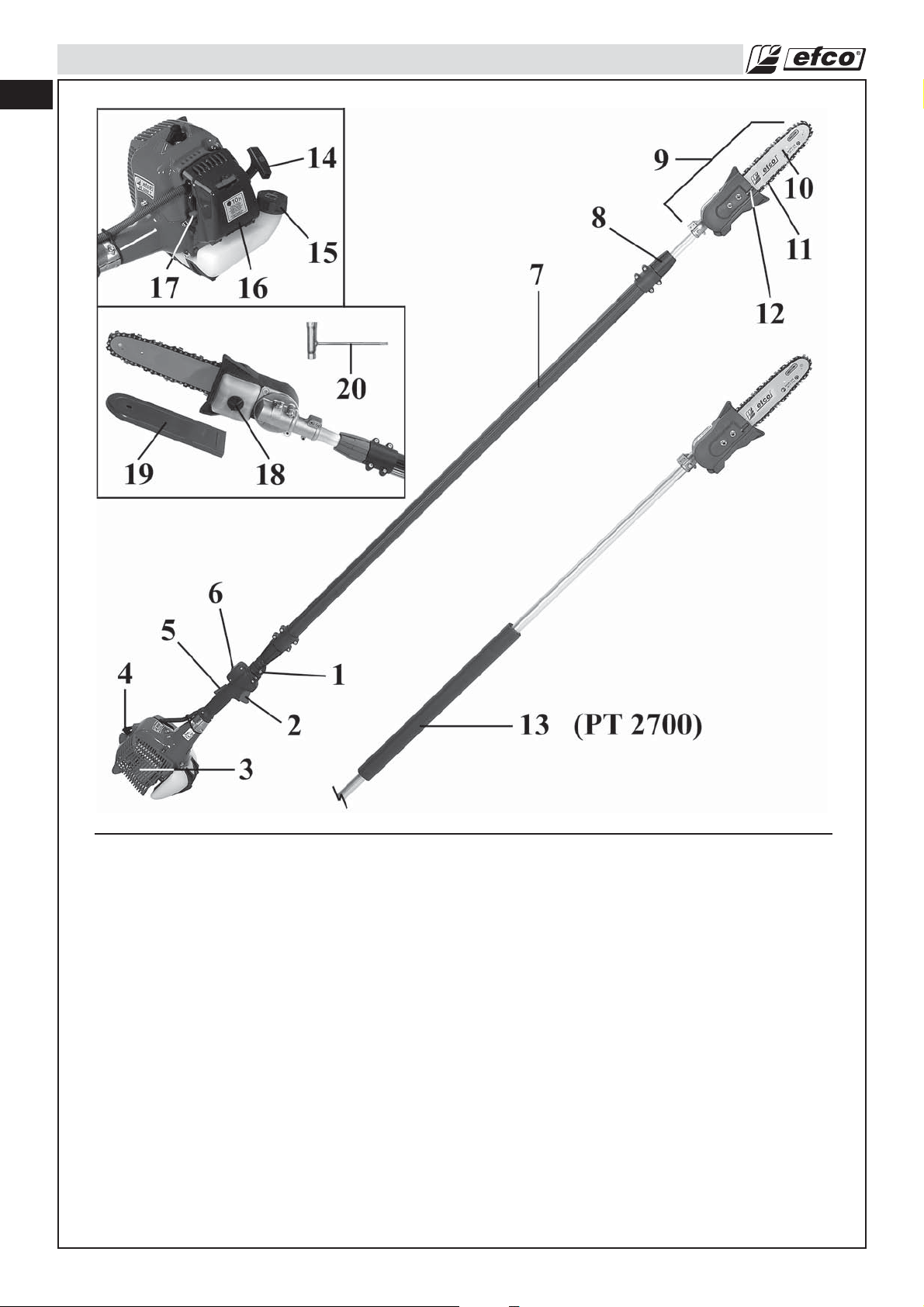
Pole pruner Components
Harness attachment1.
Throttle Trigger2.
Muffler Guard3.
Spark plug4.
Throttle Trigger Lockout5.
On/Off Switch6.
Shaft arm7.
Locking ring nut8.
Cutting implement EP 120 EF9.
Guide Bar10.
4
Chain11.
Guide Bar Adjusting Screw12.
Handle (PT 2700)13.
Starter Handle14.
Fuel Tank Cap15.
Air Filter Cover16.
Choke Lever17.
Oil Tank Cap18.
Bar Cover19.
Combination Wrench20.
Page 5
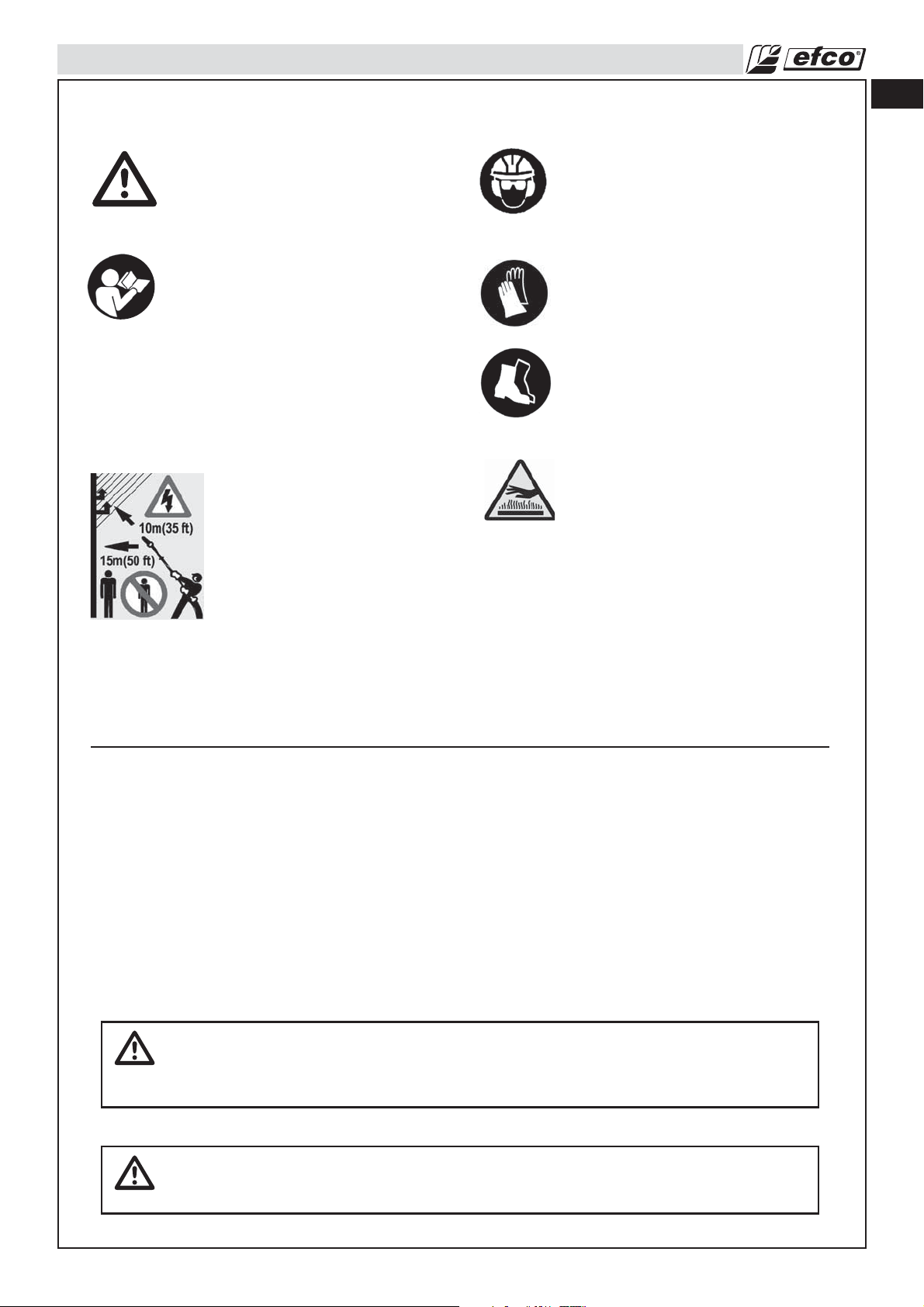
Understanding Safety Labels
SAFETY
en
- This symbol indicates Warning, and
Caution.
- Your manual contains special
messages to bring attention to
potential safety concerns, machine
damage as well as helpful operating
and servicing information. PLEASE
READ ALL THE INFORMATION
CAREFULLY TO AVOID INJURY
AND MACHINE DAMAGE.
- The machineis not electrically
insulated so avoid contact
with high voltage lines. Never
approach the implement at
less than 10 metres from
electric lines. Keep bystanders
away 15 m.
- Wear eye, hearing and head
protection when operating this
equipment.
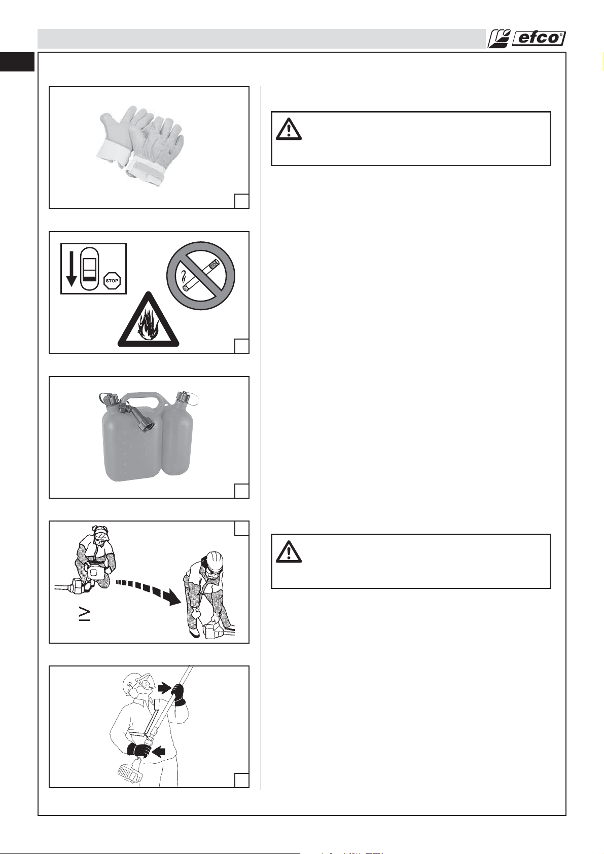
- Wear non-slip, heavy-duty
protective gloves when handling.
- Wear safety strong shoes or boots
having skid-proof sole and
anti-piercing insert.
- WARNING! The surface can be
hot!
State and Local Requirements
Your pole pruner is equipped with a temperature limiting muffler, a spark arresting screen in order to
comply with the requirements of SAE Recommended Practice J335 and California Codes 4442 and 4443.
All national forest land and land managed by the states of California, Maine, Washington, Idaho,
Minnesota, New Jersey and Oregon require internal combustion engines to be equipped with a
spark arrester screen by law. Other states and federal agencies are enacting similar regulations. If you
operate a pole pruner in a state or locale where such regulations exist, you are legally responsible for
maintaining the operating condition of these parts. Failure to do so is a violation of a law. Spark arrester
maintenance is described in the Maintenance-Spark Arresting Muffler Section of the manual.
Note: When using a pole pruner for logging purposes, refer to Code of Federal Regulations, Parts
1910 and 1928.
WARNING: The ignition system of your unit produces an electromagnetic field of a very
low intensity. This field may interfere with some pacemakers. To reduce the risk of
serious or fatal injury, persons with pacemaker should consult their physician and the
pacemaker manufacturer before operating this tool.
WARNING: Muffler surfaces are very hot during and after operation of the pole pruner,
keep all body parts away from the muffler. Serious burns may occur if contact is made
with the muffler.
5
Page 6

en
SAFETY
WARNING: Exposure to vibrations through prolonged use of gasoline powered hand
tools could cause blood vessel or nerve damage in the fingers, hands, and wrists of
people prone to circulation disorders or abnormal swellings. Prolonged use in cold
weather has been linked to blood vessel damage in otherwise healthy people. If
symptoms occur such as numbness, pain, loss of strength, change in skin color or
texture, or loss of feeling in the fingers, hands, or wrists, discontinue the use of this tool
and seek medical attention.
WARNING: The engine exhaust from this product contains chemicals known to the
State of California to cause cancer, birth defects or other reproductive harm. Operate
your pole pruner outdoors only in a well ventilated area.
6
Page 7
50 ft
35 ft
SAFETY RULES
Basic Safety Precautions
• Read this manual carefully until you completely understand
and can follow all safety rules, precautions, and operating
instructions before attempting to use the unit.
• Restrict the use of your pole pruner to adult users who
understand and can follow safety rules, precautions, and
operating instructions found in this manual. Minors should
never be allowed to use a pole pruner.
1
2
3
4
5
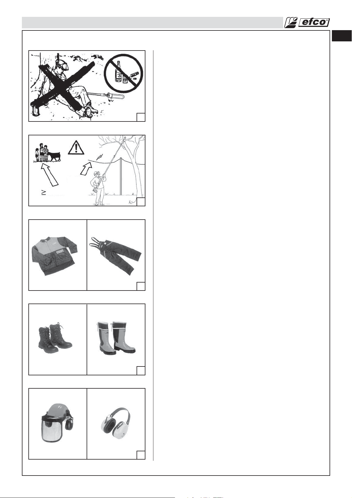
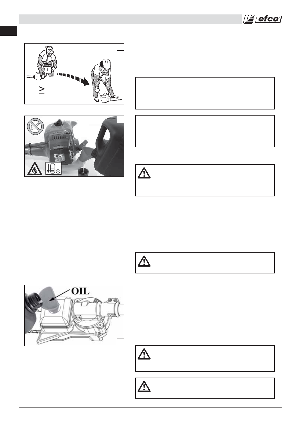
• Do not handle or operate a pole pruner when you are fatigued,
ill, or upset, or if you have taken alcohol, drugs, or medication.
You must be in good physical condition and mentally alert.
Pole pruner work is strenuous. If you have any condition that
might be aggravated by strenuous work, check with your
doctor before operating a pole pruner (Fig. 1). Be more
cautious before rest periods and towards the end of your
shift.
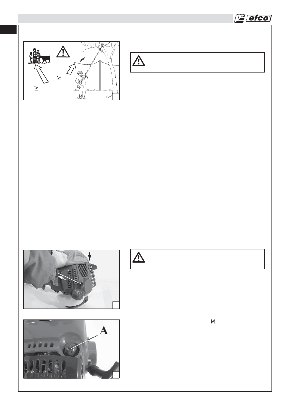
• Keep children, bystanders, and animals a minimum of 35 feet
(10 meters) away from the work area. Do not allow other
people or animals to be near the pole pruner when starting or
operating the pole pruner (Fig. 2).
• Major cases of pole pruner accidents happen when the chain
hits the operator. While working with the pole pruner, always
use safety protective approved clothing. The use of protective
clothing does not eliminate injury risks, but reduces the injury
effects in case of accident. Consult your trusted supplier to
choose equipment in compliance with legislation. The clothing
must be proper and not an obstacle. Wear adherent anti-cut
clothing. Anti-cut jackets (Fig.3), dungarees (Fig.3) and
leggings are ideal. Do not wear clothes, scarves, ties or
bracelets that may get stuck in wood or twigs. Tie up and
protect long hair (example with foulards, cap, helmets, etc.).
Safety shoes or boots having skid-proof sole and
anti-piercing insert (Fig.4). Wear protective helmet (Fig.5)
in places where there can be falling objects. Wear protective
goggles or face screens! Use protections against noises:
for example noise reduction ear guards (Fig.5) or earplugs.
The use of protections for the ear requests much more
attention and caution, because the perception of danger audio
signals (screaming, alarms, etc.) is limited. Wear anti-cut
gloves (Fig.6, page 8).
• Only loan your pole pruner to expert users who are completely
familiar with pole pruner operation and correct use. Give other
users the manual with operating instructions, which they have
to read before using the pole pruner.
• Check the pole pruner each day to ensure that each device,
whether for safety or otherwise, is functional.
• Never use a damaged, modified, or improperly repaired or
assembled pole pruner. Do not remove, damage or deactivate
any of the safety devices. Only use bars of the length indicated
by the manufacturer. Always replace bar, chain, immediately if
it becomes damaged, broken or is otherwise removed.
• Carefully plan your pole pruning operation in advance. Do not
start cutting until you have a clear work area, secure footing,
and planned retreat path.
• All pole pruner service, other than the operations shown in the
present manual, have to be performed by competent personnel.
• The pole pruner must only be used for cutting wood. It is
unadvisable to cut other types of material.
• It is unadvisable to hitch tools or applications to the P.t.o. that
are not specified by the manufacturer.
en
7
Page 8
en
SAFETY RULES
Fuel Handling
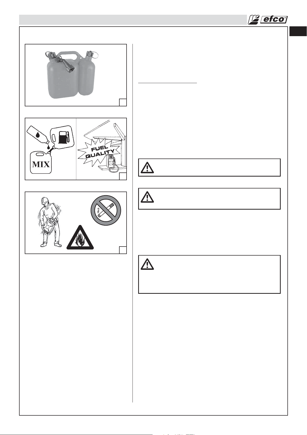
WARNING: Gasoline is an extremely flammable fuel.
Use extreme caution when handling gasoline or fuel
mix. Do not smoke or bring any fire or flame near the
fuel or the pole pruner (Fig. 7).
• To reduce the risk of fire and burn injury, handle fuel with
6
7
8
care. It is highly flammable.
• Mix and store fuel in a container approved for gasoline
(Fig. 8).
• Mix fuel outdoors where there are no sparks or flames.
• Select bare ground, stop engine, and allow to cool before
refueling.
• Loosen fuel cap slowly to release pressure and to keep fuel
from escaping around the cap.
• Tighten fuel cap securely after refueling. Unit vibration can
cause an improperly tightened fuel cap to loosen or come off
and spill quantities of fuel.
• Wipe spilled fuel from the unit. Move 10 feet (3 m) away from
refueling site before starting engine (Fig. 9).
• Never attempt to burn off spilled fuel under any
circumstances.
• Do not smoke while handling fuel or while operating the pole
pruner.
• Store fuel in a cool, dry, well ventilated place.
• Never place the pole pruner in a combustible area such as dry
leaves, straw, paper, etc.
• Store the unit and fuel in an area where fuel vapors cannot
reach sparks or open flames from water heaters, electric
motors or switches, furnaces, etc.
• Never take the cap off the tank when the engine is running.
• Never use fuel for cleaning operations.
• Take care not to get fuel on your clothing.
10 ft
9
10
Operation and Safety
WARNING: Always hold the pole pruner with both
hands when the engine is running. Use a firm grip
with thumbs and fingers encircling the pole pruner
handles (Fig. 10).
• Keep all parts of your body away from the pole pruner chain
when the engine is running.
• Always carry the pole pruner with the engine stopped the
guide bar and pole pruner chain to the rear, and the muffler
away from your body. When transporting your pole pruner, use
the appropriate guide bar scabbard (Fig. 11). When transporting
in a vehicle, keep chain and bar covered with the chain guard.
Properly secure your pole pruner to prevent turnover, fuel
spillage and damage to the pole pruner.
• Do not operate a pole pruner with one hand! Serious injury
to the operator, helpers, bystanders, or any combination of
these persons may result from one-handed operation. A pole
pruner is intended for two-handed use.
• Before you start the engine, make sure the pole pruner chain
is not contacting any object. Never try to start the pole pruner
when the guide bar is in a cut.
• Shut off the engine before setting down the pole pruner. Do not
leave the engine running unattended.
8
Page 9
SAFETY RULES
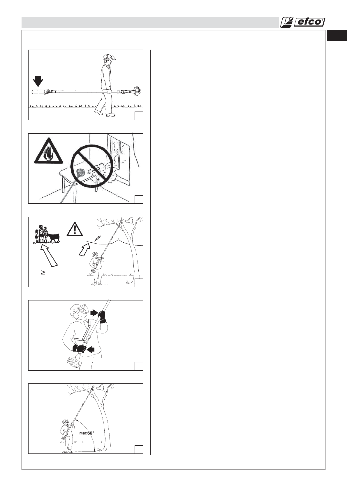
• Only use the pole pruner in well-ventilated places, do not
operate the pole pruner in explosive or flammable atmospheres
or in closed environments (Fig. 12). Beware of carbon
monoxide poisoning.
• Do not operate pole pruner from a ladder or in a tree. Always
cut from a firm-footed and safe position.
• Do not put pressure on the pole pruner at the end of the cut.
Applying pressure can cause you to lose control when the cut
is completed.
11
12
• Do not cut near electric cables (Fig. 13).
• Keep the handles dry, clean, and free of oil or fuel mixture.
• When the pole pruner is running, grip the front handle firmly
with your left hand and the back handle with your right hand
(Fig. 10).
• When cutting a limb that is under tension, be alert for
springback so you will not be struck when the tension in the
wood fibre is released.
• Take great care when cutting small branches or shrubs which
can block the chain, be thrown back towards you or cause you
to lose your balance.
• Never start up the pole pruner without the chain cover fitted.
• Do not use the pole pruner as a lever for lifting, moving or
splitting objects. Do not lock it over fixed stands..
• Always begin cutting with the engine at full speed .
en
50 ft
35 ft
13
14
Maintain Control (Fig. 14-15)
• Keep a good, firm grip on the pole pruner with both hands
when the engine is running and don’t let go. A firm grip will
help you reduce kickback and maintain control of the pole
pruner. Keep your right hand completely around the rear
handle whether you are right handed or left handed. Keep your
left arm straight with the elbow locked.
• Position your left hand on the front handlebar so it is in a straight
line with your right hand on the rear handle when making
bucking cuts. Never reverse right and left hand positions for
any type of cutting.
• Stand with your weight evenly balanced on both feet.
• Stand slightly to the left side of the pole pruner to keep your
body from being in a direct line with the cutting chain.
• Do not overreach. You could be drawn or thrown off balance
and lose control of the pole pruner.
15
9
Page 10
en
SAFETY RULES
Precautions to Reduce Vibration Risk
• The pole pruner is provided with anti-vibration (AV) system; never alter or modify it.
• Wear gloves and keep your hands warm.
• Keep the pole pruner chain sharp and the pole pruner, including the AV system, well maintained. A dull chain
will increase cutting time, and pressing a dull chain through wood will increase the vibrations transmitted
to your hands.
• Maintain a firm grip at all times, but do not squeeze the handles with constant, excessive pressures, take
frequent breaks. All the above mentioned precautions do not guarantee that you will not sustain
whitefinger disease or carpal tunnel syndrome. Therefore, continual and regular users should monitor
closely the condition of their hands and fingers. If any of the above symptoms appear, seek medical
advice immediately.
Maintenance Precaution
WARNING: Never operate a pole pruner that is damaged, improperly adjusted, or is not
completely and securely assembled.
• Be sure that the pole pruner chain stops moving when the throttle control trigger is released. If the pole
pruner chain moves at idle speed, the carburetor may need adjusting, see Operation-Carburetor Adjusting
Section.
If the pole pruner chain still moves at idle speed after adjustment has been made, contact a Servicing
Dealer for adjustment and discontinue use until the repair is made.
WARNING: All pole pruner service, other than items in the Operator's Manual maintenance
instructions, have to be performed by competent pole pruner service personnel. (If
improper tools are used to remove the flywheel or clutch, or if an improper tool is used to
hold the flywheel in order to remove the clutch, structural damage to the flywheel could
occur which could subsequently cause the flywheel to burst and serious injury could
result.)
• Never modify your pole pruner in any way.
• Keep the handles dry, clean, and free of oil or fuel mixture.
WARNING: Use only accessories and replacement parts recommended.
• Never touch the chain or attempt to service the pole pruner while the engine is running.
• Never use fuel for cleaning operations.
• Keep the pole pruner in a dry place, off the ground with the chain guard on and the tanks empty.
• If your pole pruner is no longer usable, dispose of it properly without damaging the environment by
handing it in to your local Dealer who will arrange for its correct disposal.
• Replace immediately any safety device when damaged or broken.
10
WARNING: The muffler and other parts of the engine (e.g. fins of the cylinder, spark plug)
become hot during operation and remain hot for a while after stopping the engine.
To reduce risk of burns do not touch the muffler and other parts while they are hot.
Page 11
ASSEMBLY
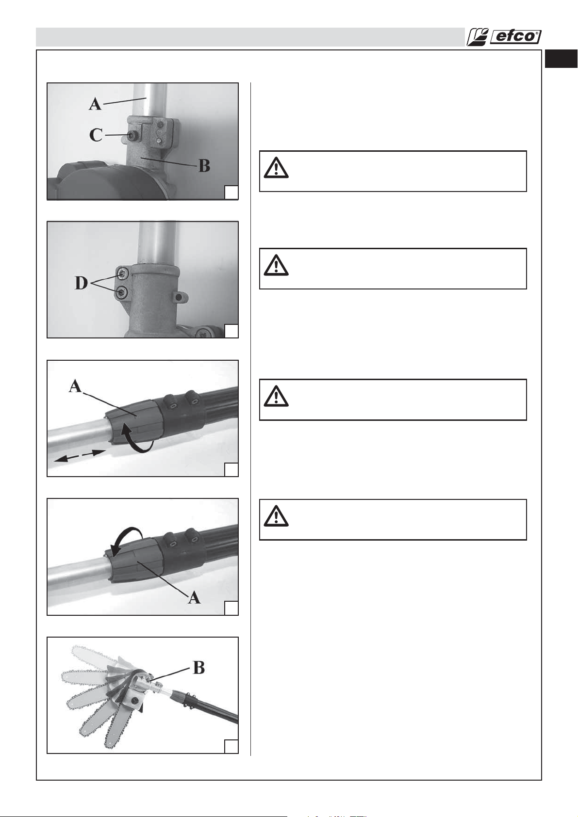
Cutting implement assemblage
Put the shaft arm (A, Fig.16) in the cutting implement (B), till the
centering hole on the shaft matches that of the implement.
Fix the centering screw (C, Fig.16) first and then the two screws
(D, Fig. 17).
16
Shaft adjustment (PTX 2700)
Unloose locking ring nut (A, Fig.18) clockwise. Adjust shaft to
desired height. Tighten locking ring nut (A, Fig.19)
17
anticlockwise.
en
WARNING! – For all operations before the use of
cutting implement, consult EP120 EF accessory
instruction manual.
WARNING – Shaft adjustment operations must be
carried out while engine is switched off and chain
cover fi tted.
18
19
Cutting tool angular adjustment (EP120 EF)
WARNING – The cutting tool angular adjustment must
be carried out while engine is switched off and chain
cover fi tted.
Cutting tool’s angulations can be modified from 0° to 90°
unscrewing screw (B, Fig.20). There are three intermediate
positions between 0° and 90° (22° - 45° - 67°) which block the
cutting tool.
After selecting the angle tighten the screw (B).
WARNING – Be aware to block the cutting device in
one of the fi fth positions; don’t let it in an intermediate
position.
20
11
Page 12
en
OPERATION
Preparing to work
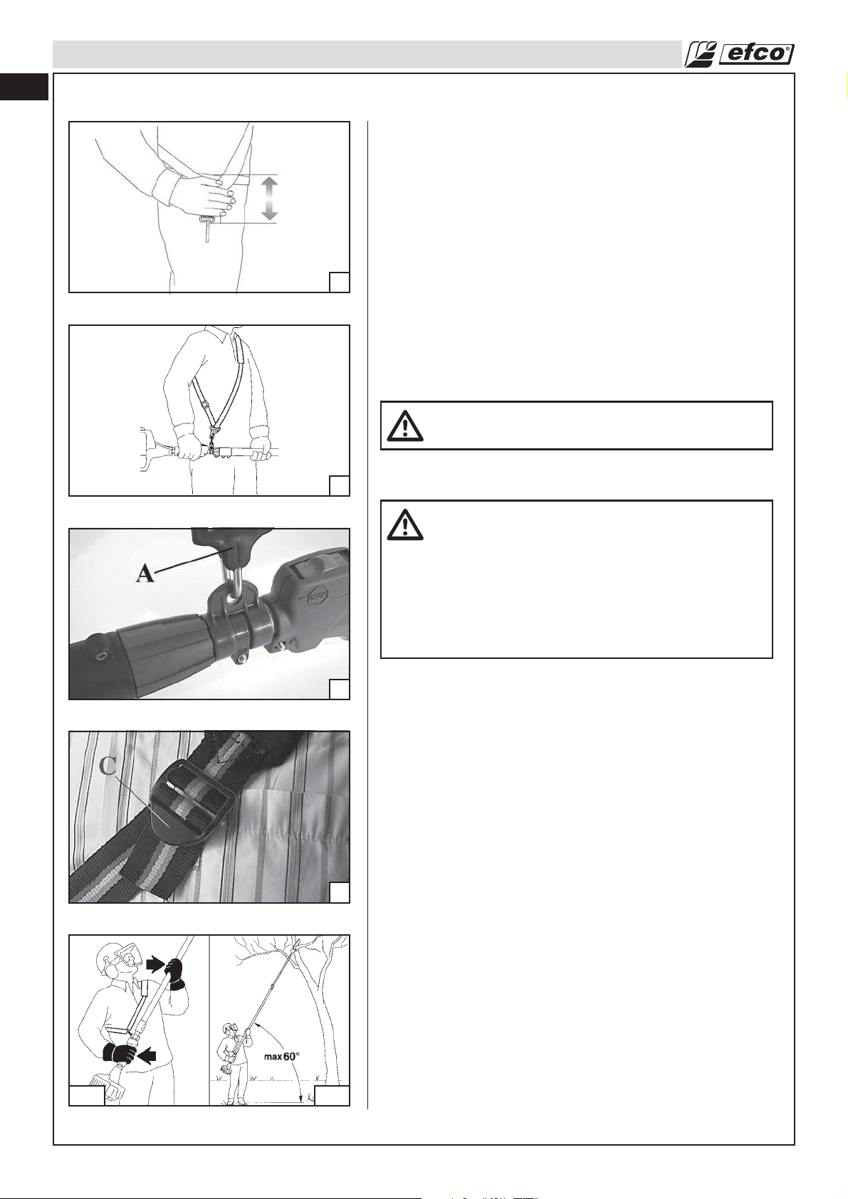
HARNESS
Correct adjustment of the harness permits the pole pruner to be
properly balanced and at an appropriate height from the ground
(Fig. 21).
- Put on the single harness (Fig. 22).
- Hook the pole pruner to the harness using the hook
(A, Fig. 23).
21
- Position the buckle (C, Fig. 24) to obtain the correct pole
pruner height.
OPERATION
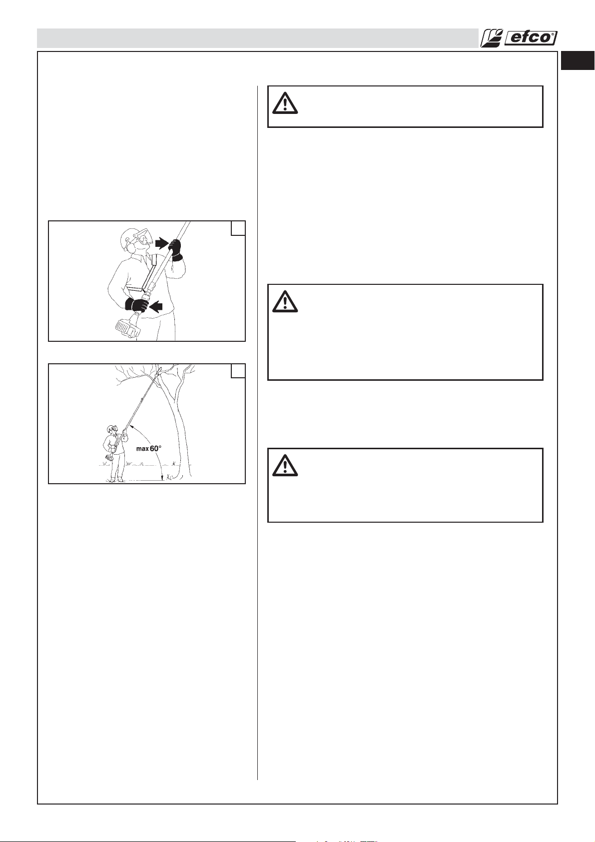
- Put on the harness and always keep both hands on the handle
while operating the pole pruner (Fig. 25A).
- Use the pole pruner as illustrated in Fig. 25B.
WARNING: Carefully read the safety precautions
before using the pole pruner.
22
23
24
OPERATING INSTRUCTIONS
WARNING - The pole pruner must only be used for
cutting branch. It is forbidden to cut other types
of material. Vibrations and kickback vary with
different materials and the requirements of the
safety regulations would not be respected. Do not
use the pole pruner as a lever for lifting, moving or
splitting objects. Do not lock it over fixed stands.
It is forbidden to hitch tools or applications to the
P.t.o. that are not specified by the manufacturer.
25A 25B
12
Page 13
OPERATION
Operating techniques
Hold control grip with right hand and shaft (Fig.25A) with left hand. On
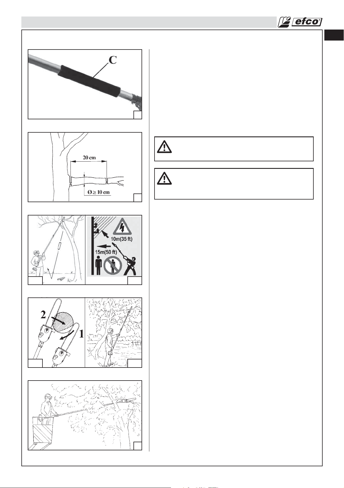
PT 2700 Models left hand should hold sheath (C,Fig.26) area.
Optimum balance could be obtained with machine close the
body. Standing 60° with the ground (Fig.25B) makes work less
fatiguing.
To ease branch falling, cut lower branches fi rst.
To cut larger branches (with diameter larger than 10 cm), cut it
26
27
into more parts (max length 20 cm), never cut the whole branch
(Fig.27).
Always cut at full throttle.
en
WARNING – Never work under the branch you are
cutting; beware of available space and falling pieces
that bounce anomalously on the ground (Fig.28A).
WARNING – Pay attention when working near electric
lines. Falling branches could cause short circuit. Never
approach the tool at less than 10 metres from electric
lines (Fig.28B).
28A 28B
29A 29B
Flush-cutting (Fig.29A) - To avoid tearing the bark, kickbacks or
bar pinching, always start by performing a relieving cut (1) on the
underside of the branch. Perform the cross-cut (2).
Particular cuts (PTX 2700)
The pole pruner permits:
- pruning of branches that are overhanging obstacles (Fig.29B)
such as rivers, lakes etc.
- pruning of branches from high rise buckets (Fig.30).
30
13
Page 14
en
.050" (1.25 mm)
OPERATION
Chain Tension
31
32
33
1. Stop the engine before setting the chain tension. Loosen
For warm chain, see Item 3.
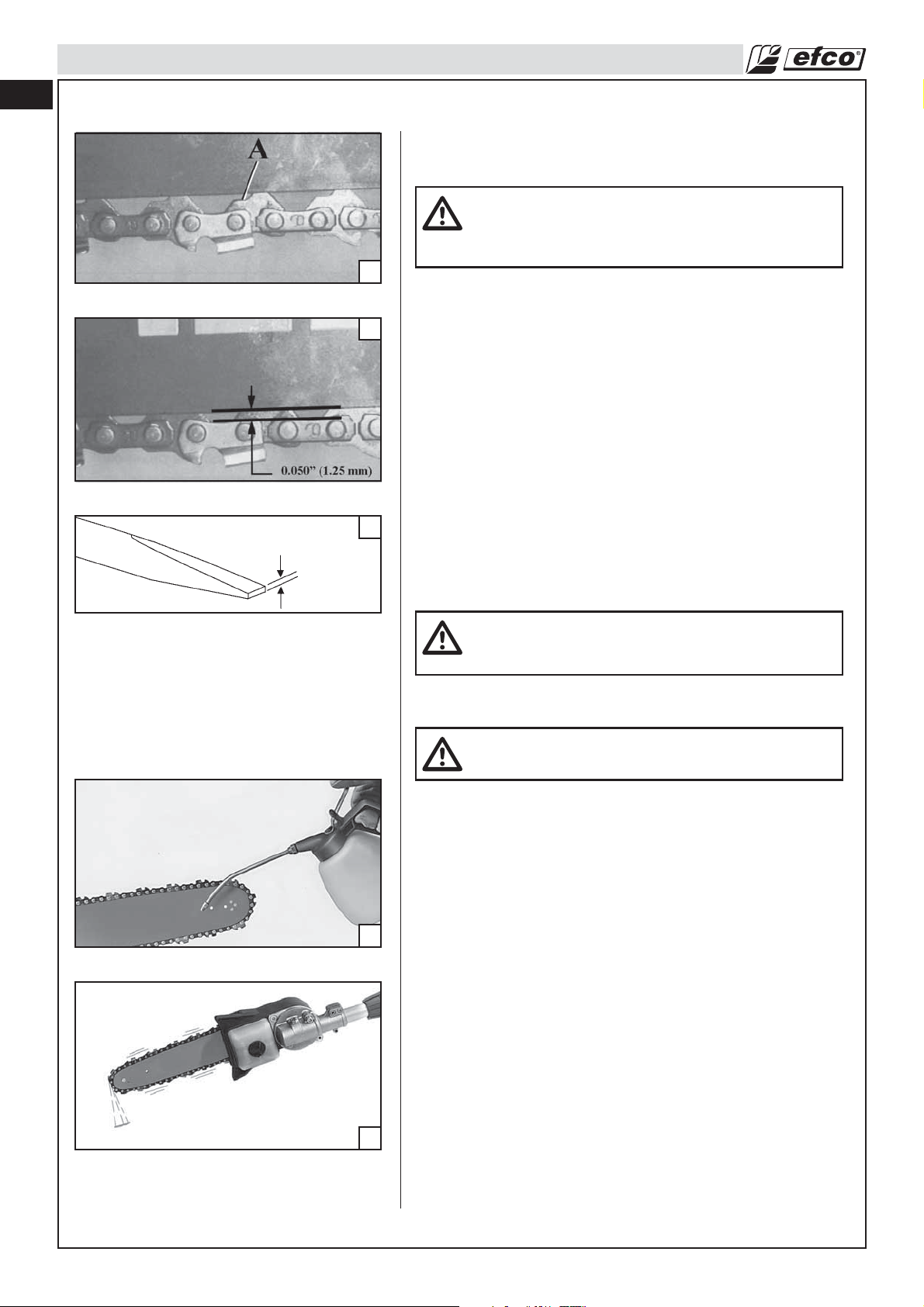
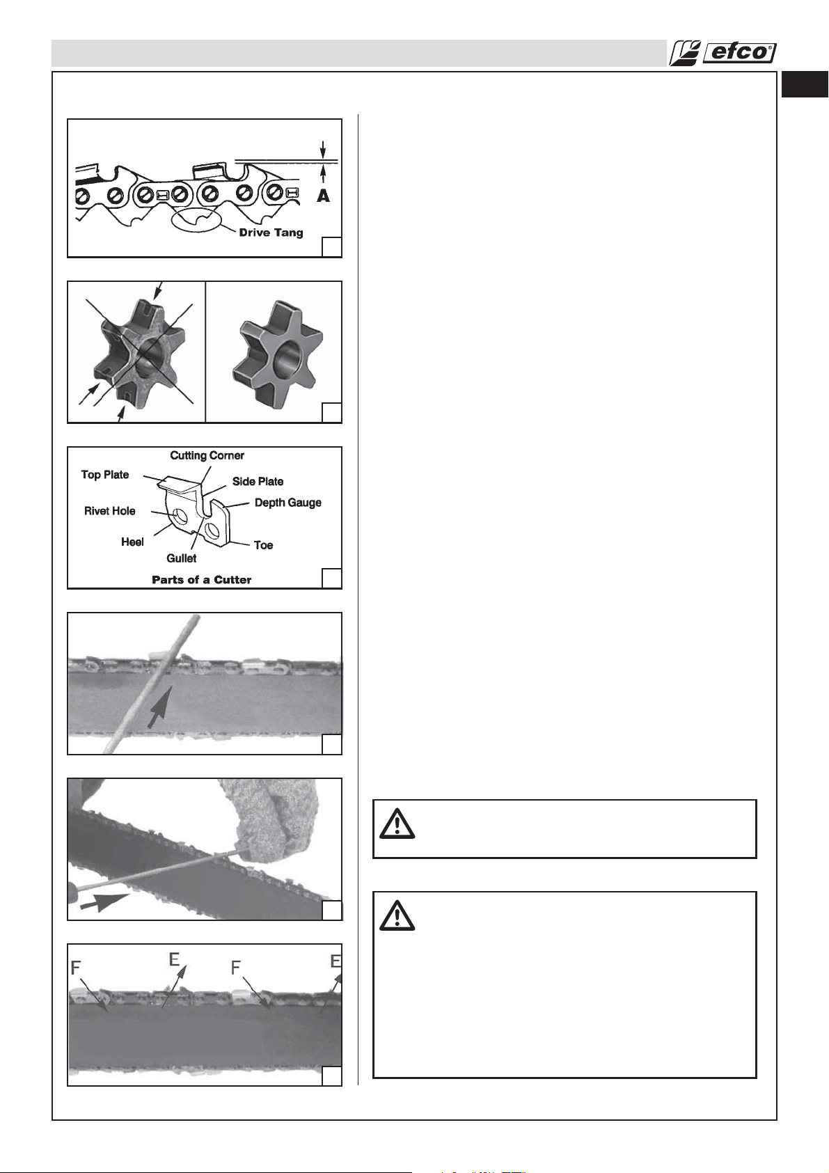
2. Chain must be retensioned whenever the flats (A) on the drive
3. During normal pole pruner operation, the temperature of the
WARNING: Never touch or adjust the chain while the
motor is running. The pole pruner chain is very
sharp, always wear protective gloves when performing
maintenance to the chain.
the guide bar nuts slightly, turn the chain tensioning screw
clockwise to tension the chain. Refer to Assembly-Assembling
the Bar and Chain Section. Retighten guide bar nuts. A cold
chain is correctly tensioned when there is no slack on the
underside of the guide bar, the chain is snug, but it can be
turned by hand without binding.
link tangs hang out of the bar groove. See Fig. 31.
chain will increase. The drive link tangs of a correctly tensioned
warm chain will hang approximately .050” (1.25 mm) out of
the bar groove. See Fig. 32. To help determine the correct
warm chain tension, the tip of the combination wrench
(Fig. 33) can be used as a guide.
34
35
CAUTION: Chain tensioned while warm, may be too
tight upon cooling. Check the "cold tension" before
next use.
CAUTION: A new chain has to be retensioned more
often than one that has been in use for some time.
Breaking-in the Chain
New chains will stretch and must be tightened frequently.
Lift the chain out of the bar groove and lubricate the bar groove
with additional oil, see Fig. 34. Place the pole pruner on a piece
of cardboard or scrap plywood. Start the pole pruner (refer to the
Operation-Starting Engine Section) and allow it to run at moderate
speed for approximately one (1) minute. Stop the engine. Check
that the oil pump is working properly. The cardboard should have
excess oil from the chain rotation if the oil pump is working
properly, see Fig. 35. Adjust the chain tension (refer to
Operation-Chain Tension Section). Start the pole pruner again
and make a few cuts in a log to heat up the chain. Stop the
engine and re-adjust chain again. Repeat this process until the
chain retains proper warm tension adjustment as shown in Fig.
32 in Operation-Chain Tensioning Section. Never touch the
ground with the chain.
14
Page 15
OPERATION
Fueling (Do Not Smoke!) (Fig. 38)
This product is powered by a 2-cycle engine and requires
pre-mixing gasoline and 2-cycle oil. Pre-mix unleaded gasoline
and 2-cycle engine oil in a clean container approved for gasoline
(Fig. 36).
RECOMMENDED FUEL: THIS ENGINE IS CERTIFIED TO
OPERATE ON UNLEADED GASOLINE INTENDED FOR
AUTOMOTIVE USE WITH AN OCTANE RATING OF 89 ([R + M] /
36
37
2) OR HIGHER (Fig. 37).
Mix 2-Cycle Engine Oil with gasoline according to the instructions
on the package. We strongly recommend the use of 2% (1:50)
Efco Two Cycle Engine Oil, which is specifically formulated for all
Efco air-cooled two-stroke engines.
The correct oil / fuel proportions shown in the table below are
suitable when using the Efco Two Cycle Engine Oil or an
equivalent high-quality engine oil (JASO specification FD or ISO
specification L-EGD). When oil specifications are NOT equivalent
or unknown use 4% (1:25) oil / fuel mixing ratio.
en
CAUTION: DO NOT USE AUTOMOTIVE OIL OR
2-CYCLE OUTBOARD OIL.
38
CAUTION: Never use a fuel with an alcohol percentage
higher than 10%; gasohol up to 10% alcohol or E10
fuel are acceptable.
When using an Oxygenated Gasoline a good practice of Fuel
Management is necessary.
Gasoline Oxygenated with alcohol readily takes/up water when it
is present; the water may be condensed out of humid air or be a
contaminant in the fuel system, including tank.
CAUTION:
- Match your fuel purchases to your consumption;
don’t buy more than you will use in one or two
months;
- Store gasoline in a tightly-closed container in a
cool, dry place.
The use of Oxygenated Gasoline may cause the occurrence of
vapor-lock easier.
15
Page 16
en
OPERATION
10 ft
39
40
NOTE: 2-Cycle Engine Oil contains a fuel stabilizer and will stay
fresh up to 30 days. DO NOT mix quantities larger than usable in
a 30 day period. A 2-cycle oil containing a fuel stabilizer is
recommended.
Fuel Mixture
2-Cycle Engine Oil (25:1) 4%
Gasoline Oil
1 Gallon (US) . . . . . . . . . . . . . . . . . . . . . . . . . . . 5.2 oz.
1 Liter . . . . . . . . . . . . . . . . . . . . . . . . . . . . . . . . . 40 cc (40 ml)
High Quality 2-Cycle Engine Oil (50:1) 2%
Gasoline Oil
1 Gallon (US) . . . . . . . . . . . . . . . . . . . . . . . . . . . 2.6 oz.
1 Liter . . . . . . . . . . . . . . . . . . . . . . . . . . . . . . . . . 20 cc (40 ml)
Filling the Tank (Fig. 40)
WARNING: Follow safety instruction for fuel handling.
Always shut off engine before fueling. Never add fuel
to a machine with a running or hot engine. Move at
least 10 feet (3 m) from refueling site before starting
engine (Fig. 39). DO NOT SMOKE!
41
1. Clean surface around fuel cap to prevent contamination.
2. Loosen fuel cap slowly.
3. Carefully pour fuel mixture into the tank. Avoid spillage.
4. Prior to replacing the fuel cap, clean and inspect the gasket.
5. Immediately replace fuel cap and hand tighten. Wipe up any
fuel spillage.
NOTE: It is normal for smoke to be emitted from a new engine
during and after first use.
WARNING: Check for fuel leaks, if any are found,
correct before use. Contact a Servicing Dealer if
necessary.
Chain Oil System (Fig. 41)
The bar and chain require continuous lubrication. Lubrication is
provided by the automatic oiler system when the oil tank is kept
filled. Lack of oil will quickly ruin the bar and chain. Too little oil will
cause overheating shown by smoke coming from the chain and/or
discoloration of the bar. In freezing weather oil will thicken, making it
necessary to thin bar and chain oil with a small amount (5 to 10%)
of Diesel Fuel or kerosene. Bar and chain oil must be free flowing for
the oil system to pump enough oil for adequate lubrication.
CAUTION: Never use waste oil. Always use
biodegradable lubrificant that is specific for bar and
chain and that is better for the environment and pole
pruner’s parts.
16
CAUTION: Do not use dirty, used or otherwise
contaminated oils. Damage may occur to the oil
pump, bar, or chain.
Page 17
OPERATION
WARNING: Do not use waste oil! Medical studies
have shown that renewed contact with waste oil can
cause skin cancer.
1. Fill the oil tank every time engine is fueled. Pole pruner should
use approximately one tank of oil per tank of fuel.
2. The automatic oil pump is a positive displacement pump
operated through gears driven off the clutch drum assembly.
The pump will not oil at idle speed.
en
42
43
Preparation for Cutting
Proper Grip on Handles.
Refer to Safety Section for appropriate Safety Equipment.
1. Wear non-slip gloves for maximum grip and protection.
WARNING: Hold the pole pruner firmly with both
hands. Always keep your LEFT HAND on the front
handle and your RIGHT HAND on the rear (throttle)
handle as shown in Fig. 42, so that your body is to
the left of the chain line. Never use a cross-handed
grip, or any stance which would place your body or
arm across the chain line. Left-handers should
follow these instructions too.
2. Maintain a proper grip on the pole pruner whenever the engine
is running. The fingers should encircle the handle. Any grip in
which the thumb and fingers are on the same side of the
handle, is dangerous because a slight kick of the pole pruner
can cause loss of control.
WARNING:
Proper Cutting Stance (Fig. 43)
- Weight should be balanced on both feet - feet on
solid ground.
- Your body should always be to the left of the
chain line.
Basic Cutting Procedure
Practice cutting a few small logs using the following technique to
get the "feel" of using your pole pruner before you begin a major
pole pruning operation.
1. Take the proper stance in front of the wood with the pole
pruner idling.
2. Accelerate the engine to full throttle just before entering the cut
by squeezing the throttle trigger.
3. Keep the engine at full throttle the entire time you are cutting.
4. Allow the chain to cut for you; exert only light downward
pressure. If you force the cut, damage to the bar, chain, or
engine can result.
5. Release the throttle trigger as soon as the cut is completed,
allowing the engine to idle. If you run the pole pruner at full
throttle without a cutting load, unnecessary wear or
damage can occur to the chain, bar, and engine.
6. Do not put pressure on the pole pruner at the end of the cut.
17
Page 18
en
50 ft
35 ft
OPERATION
Work Area Precautions
• Never allow children to operate your pole pruner. Only allow
others to use this pole pruner who have read this Operator's
44
Manual or received adequate instructions for the safe and
proper use of this pole pruner.
• Keep everyone - helpers, bystanders, children, and animals a
safe distance from the cutting area (Fig. 44).
• Always cut with both feet on solid ground to prevent being
pulled off balance.
• Do not cut above chest height, as a pole pruner held higher is
difficult to control against kickback forces.
• Do not work near electrical wires or buildings. Leave this
operation for professionals.
• Cut only when visibility and light are adequate for you to see
clearly.
• Do not cut from a ladder, this is extremely dangerous.
• Stop the pole pruner if the chain strikes a foreign object.
Inspect the pole pruner and repair parts as necessary.
• Keep the chain out of dirt and sand. Even a small amount of
dirt will quickly dull a chain and increase the possibility of
kickback.
• Stop the engine before setting the pole pruner down.
• Be particularly cautious and alert while wearing hearing
protection because such equipment may restrict your ability to
hear sounds indicating danger (calls, signals, warnings, etc).
• Be extremely cautious when working on slopes or uneven
ground.
WARNING: Cut only wood or materials made from
wood. Do not cut metal, plastics, masonry, or
non-wood building materials.
45
46
Starting The Engine
WARNING: Keep body to the left of the chain line.
Never straddle the pole pruner or chain, or lean over
past the chain line.
• Do not start the engine with the arm not mounted.
• Place the pole pruner on level ground and ensure that no
objects or obstructions are in immediate vicinity which could
come in contact with the bar and chain.
Hold the body of the machine on the ground using your left
hand (CAUTION! Not with your foot!), see Fig. 45.
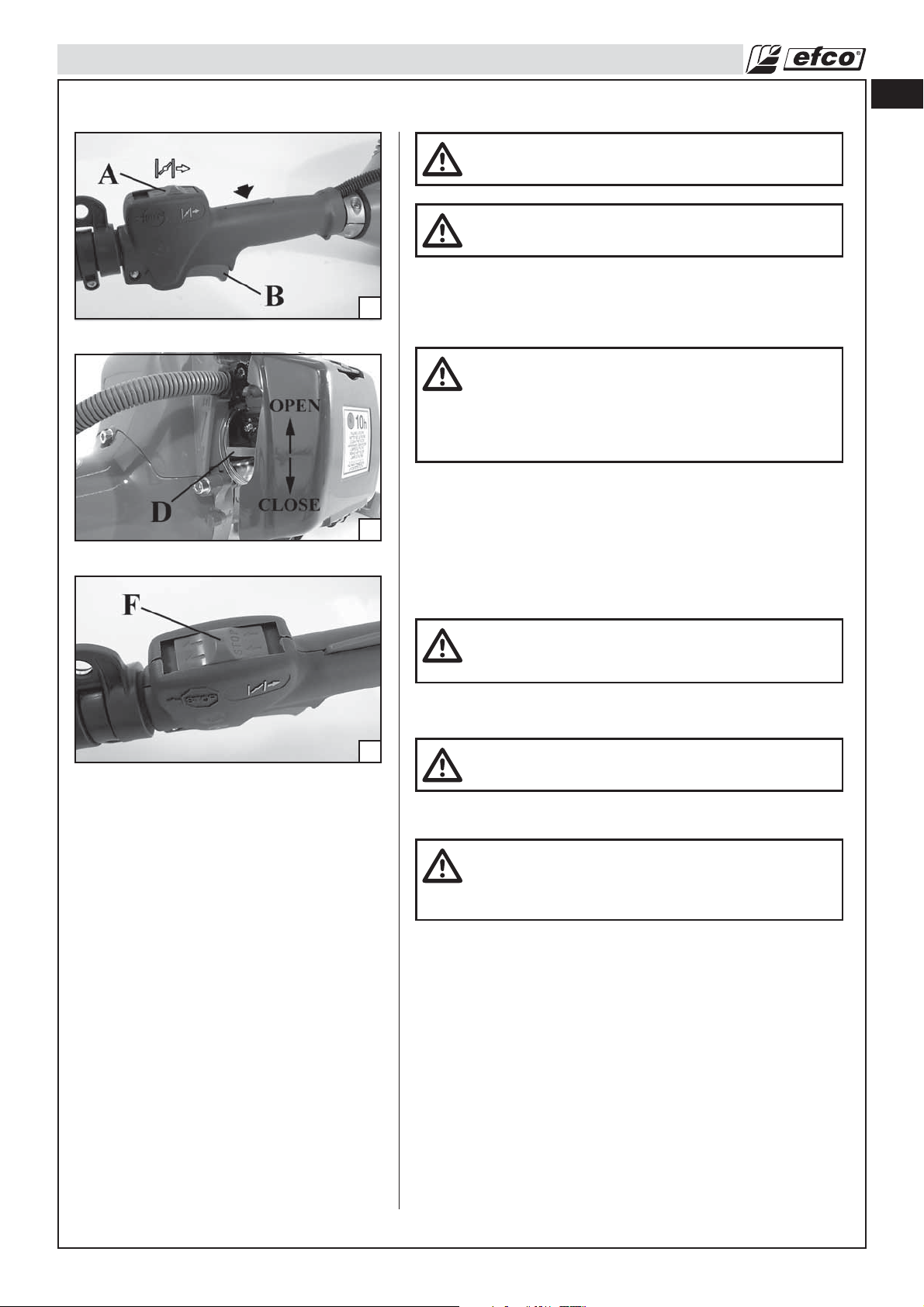
• Fill the carburetor by pushing primer bulb (A, Fig. 46).
• Pull the throttle lever (B) and stop it at half-throttle put the
ON/OFF switch (A, Fig.47) in the (
the lever (B).
• Put the choke lever (D, Fig.49) in the CLOSE position.
• Holding the pole pruner down, pull the starting rope slowly
until you meet resistance (Fig.45). Then pull it hard several
times, and when the engine starts put the choke lever
(D, Fig.48) back into its original position OPEN. Repeat until
the engine starts.
• Once the engine has started, press throttle trigger (B, Fig.47)
to release it from the half-throttle position and let the engine
idle.
) position then release
18
Page 19
OPERATION
• To start the engine when warm, switch (F) must be positioned
47
as shown in Fig.49.
en
WARNING: Once the engine is warmed up do not
use the choke to start up again.
WARNING: Use the semi-acceleration device only in
the phase of starting the engine when cold.
WARNING: Do not cut material with the choke/fast
idle lever at the FULL CHOKE position. Do not
operate your pole pruner with the starting throttle
lock engaged. Cutting with the starting throttle lock
engaged does not permit the operator proper control
of the pole pruner or chain speed.
48
49
NOTE - STARTING WARM ENGINE:
Follow above starting instructions, but do not use the Full
Choke position for start up again. To set fast idle for warm
engine starting, pull choke out completely and push back in
to the original Run Position.
WARNING: Weather conditions and altitude may
affect carburetion. Do not allow bystanders close to
the pole pruner while adjusting the carburetor.
WARNING: Never attempt to start the pole pruner
when the guide bar is in a cut or kerf.
WARNING: Never start the pole pruner engine
without the bar, chain and sprocket cover assembled
- or else the clutch can come loose and cause
personal injuries.
19
Page 20
en
OPERATION
Breaking-in the Engine
The engine reaches the maximum power after 5-8 hours of activity.
During this period of breaking-in do not make the machine
function idly at full throttle, to avoid excessive functioning
stress.
CAUTION! – During the braking-in period do not vary
the carburetion to obtain a presumed power
increment; the engine can be damaged.
51
Difficult Starting (or starting a flooded engine)
The engine may be flooded with too much fuel if it has not started
after 10 pulls. Flooded engines can be cleared of excess fuel by
following the warm engine starting procedure listed above.
Ensure the ON/STOP switch is in the ON position. Starting could
require pulling the starter rope handle many times depending on
how badly the unit is flooded. If engine fails to start refer to the
TROUBLESHOOTING TABLE (page 30).
52
53
Engine is Flooded
If you did not move the choke lever to warm start, quickly enough
after the engine began to fire, the combustion chamber is
flooded.
• Set the on/off swich to STOP.
• Engage a suitable tool in the spark plug boot (Fig. 51).
• Pry off the spark plug boot.
• Unscrew and dry off the spark plug.
• Open the throttle wide.
• Pull the starter rope several times to clear the combustion
chamber.
• Refit the spark plug and connect the spark plug boot, press it
down firmly – reassemble the other parts.
• Set the on/off swich to I, the starting position.
• Set the choke lever to warm start – even if engine is cold.
• Now start the engine.
Stopping The Engine
Release the throttle trigger (B, Fig. 52) and let the engine return
to idle.
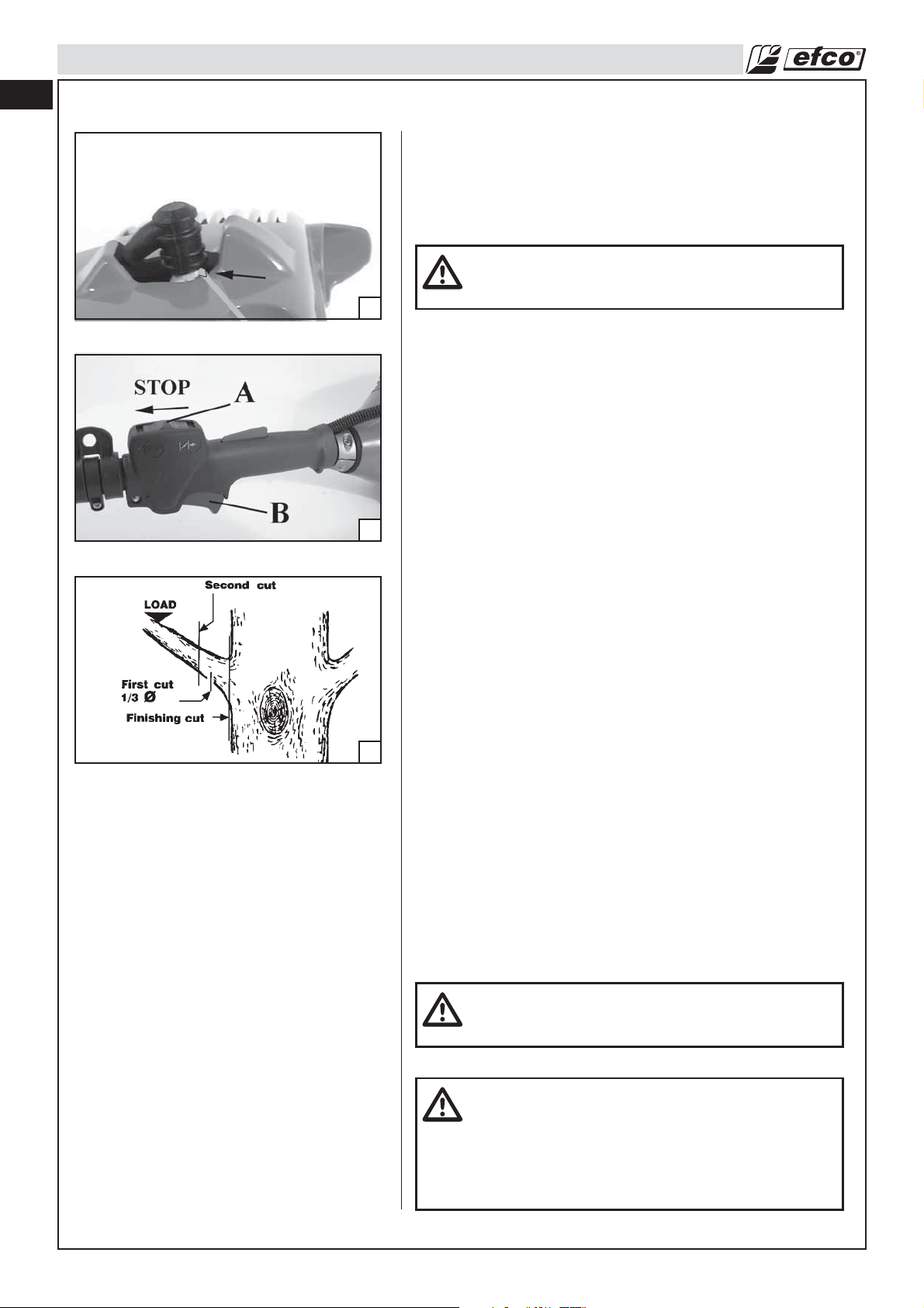
To stop the engine, move the on/off switch (A) to the “STOP”
position. Do not put the pole pruner on the ground when the saw
chain is still moving.
In the event that the “STOP” position of the switch will not
function, pull the choke lever in the CLOSE position
(Fig.48, page 19) to stop the engine.
20
CAUTION: The chain contracts as it cools down. If it
is not slackened, it could damage the sprocket shaft
and bearings.
Pre-operation checking
WARNING: THE SAW CHAIN SHOULD NEVER TURN
AT IDLE. Turn the idle speed screw “T”
counterclockwise to reduce the idle RPM and stop
the chain, or contact a Servicing Dealer for
adjustment and discontinue use until the repair is
made. Serious personal injury may result from the
pole pruner chain turning at idle.
Page 21
OPERATION
Working Techniques
Unusual Hazardous Working Techniques Conditions
WARNING: Do not work during periods of high wind or heavy precipitation.
WARNING: Never cut, when visibility is poor or in very high or low temperatures or in freezing
weather.
WARNING: Do not cut near electrical wires or buildings. If the tree makes contact with any utility line,
the utility company should be notified immediately.
WARNING: Check the tree for damaged or dead branches that could fall and hit you during
working.
• Carefully plan your pole pruning operation in advance.
• Clear the work area. You need a clear area all around the tree so you can have secure footing.
Look for decay and rot. If the branch is rotted, it can snap and fall toward the operator.
Make sure there is enough room for the branch to fall. Maintain a distance of 2-1/2 tree lengths from the nearest
person or other objects. Engine noise can drown out a warning call. Remove dirt, stones, loose bark, nails, staples,
and wire from the tree where cuts are to be made.
Pick your escape route (or routes in case the intended route is blocked). Clear the immediate area around the tree,
and make sure there are no obstructions in your planned path of retreat.
en
WARNING: Never turn pole pruner upside down to undercut. The pole pruner cannot be controlled in
this position. Always make your first cut on the compression side of the branch. The compression
side of the branch is where the pressure of the branch’s weight is concentrated.
Pruning
• Be alert for springback. Watch out for branches that are bent or under pressure. Avoid being struck by the branch
or the pole pruner when the tension in the wood fibers is released.
• Keep a clear work area. Frequently clear branches out of the way to avoid tripping over them.
WARNING: Never climb into a tree to limb or prune. Do not stand on ladders, a log or in any position
which can cause you to lose your balance or control of the pole pruner.
Pruning Operation (Fig. 53)
• When pruning trees it is important not to make the flush cut next to the main limb or trunk until you have cut off
the limb further out to reduce the weight. This prevents stripping the bark from the main member.
• Underbuck the branch 1/3 through for your first cut, your second cut should overbuck to drop the branch off.
• Now make your finishing cut smoothly and neatly against the main member so the bark will grow back to seal the
wound.
21
Page 22

en
MAINTENANCE
Maintenance Chart
Please note that the following maintanance intervals apply for normal operating conditions only. If your
daily work requires longer than normal or harsh cutting conditions are present the suggested intervals
should be shortened accordingly.
Complete Machine Inspect (Leaks, Cracks, and Wear)
Clean
Controls (Ignition Switch, Choke Lever, Throttle Trigger,
Trigger Interlock)
Fuel Tank Inspect (Leaks, Cracks, and Wear)
Oil Tank Inspect (Leaks, Cracks, and Wear)
Fuel Filter Inspect
Chain Lubrication Check Output
Saw Chain Inspect (Damage, Sharpness, and Wear)
Guide Bar Inspect (Damage and Wear)
Rim Sprocket Inspect (Damage and Wear)
Clutch Drum Inspect (Damage and Wear)
Chain Catcher Inspect (Damage and Wear)
All Accessible Screws and Nuts (Not Adjusting Screws) Inspect
Air Filter Clean
Cylinder Fins Clean
Starter System Vents Clean
Starter Rope Inspect (Damage and Wear)
Carburetor Check Idle (Chain must not rotate at idle)
Spark Plug Check Electrode Gap
Check Operation
Clean
Clean
Clean, Replace Filter Element
Check Tension
Sharpen (Check Gauge Depth)
Clean Bar groove and Oil Passages
Rotate
Lubricate Sprocket Nose
Deburr
Replace
Replace
Replace
Retighten
Replace
Replace
Replace
After Each
Refueling Stop
Before Each Use
XX
XX
XX
XX
XX
XX
XX
XX
X
XX
X
XX
XX
Weekly
Daily Work
After Finishing
X
X
X
X
X
X
X
X
X
X
X
X
X
X
Faulty
Monthly
If Damaged or
X
XX
XX
X
XX
X
X
X
As Required
Every 6
Months
Replace with
every new chain
Every 6
Months
Every 6
Months
22
Page 23
MAINTENANCE
Assembling the Bar and Chain
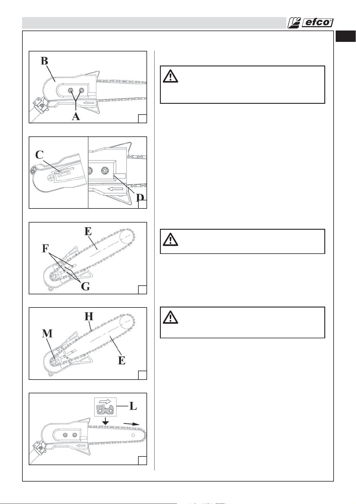
1. Remove the two (2) bar nuts (A, Fig. 55) and the cover (B).
55
56
2. Adjust the chain tensioning pin (C) fully towards the cover
band by turning the chain tensioning screw (D) counterclockwise
as shown in inset (Fig. 56).
3. The guide bar (E, fig. 57) contains a bar stud slot that fits over
the bar studs (F). The guide bar also contains two chain
tensioning pin holes (G) and two lubrication holes, one per
side. The bar is reversible and either tensioning pin hole may
be utilized with the chain tensioning pin.
4. Place the guide bar (E) onto the bar studs (F) as shown in
Fig. 57.
5. Position the guide bar (E) tip through the chain (H) loop as
shown in Fig. 58. The cutters on the top of the guide bar
should face toward the bar nose, in the direction of the chain
rotation. See inset (L) of Fig. 59.
6. Fit the chain (H, fig. 58) over the rim sprocket (M) and into bar
groove.
en
WARNING: Check the chain tension frequently when
operating the pole pruner. Never touch or adjust the
chain while the engine is running. The pole pruner
chain is very sharp, always wear protective gloves
when performing maintenance to the chain.
57
58
CAUTION: Severe damage can occur to the rim
sprocket, clutch drum, guide bar and chain, if the
chain is not correctly seated into the rim sprocket.
7. Replace the cover (B). Turn the chain tensioning screw (D)
clockwise until the chain tensioning pin (C) fits into the chain
tensioning pin hole (G). Install the two bar nuts (A). Tighten the
bar nuts finger tight only. The bar must be free to move for
tension adjustment.
CAUTION: Failure to ensure that the chain tensioning
pin is in the chain tensioning pin hole will result in
severe damage to the pole pruner during reassembly
of the sprocket cover.
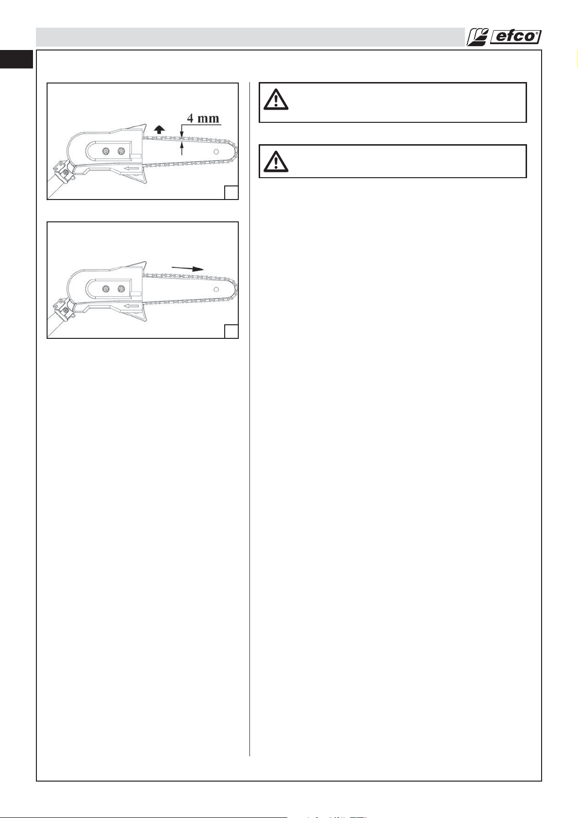
8. Remove all slack from chain by turning the chain tensioning
screw (D) clockwise, assuring that the chain seats into the
bar groove during tensioning.
9. Lift the tip of the guide bar up to check for sag, see Fig. 60,
pag. 24. Release the tip of the guide bar, and turn the chain
tensioning screw (D) 1/2 turn clockwise. Repeat this process
until sag does not exist.
10. Hold the tip of the guide bar up and tighten the bar nuts (A)
securely as shown in Fig. 55.
11. Chain is correctly tensioned when there is no slack on the
underside of the guide bar, the chain is snug, but it can be
turned by hand without binding, see Fig. 61.
59
NOTE: If chain is too tight, it will not rotate. Loosen bar nuts
slightly and turn adjusting screw 1/4 turn counterclockwise.
Lift the tip of the guide bar up and retighten bar nuts.
23
Page 24
en
MAINTENANCE
WARNING: If the pole pruner is operated with a
loose chain, the chain could jump off the guide bar
and result in serious injury.
WARNING: Never start the pole pruner with the
sprocket cover loose.
60
61
24
Page 25
MAINTENANCE
Chain Maintenance
For smooth and fast cutting, raker chain needs to be maintained
properly. The chain requires sharpening when the wood chips are
small and powdery, the chain must be forced through the wood
during cutting, or the chain cuts to one side. During maintenance
of your chain, consider the following:
1. Improper filing angle of the side plate can increase the risk of
62
a severe kickback.
2. Raker (depth gauge) clearance (A, Fig. 62): Too much increases
the potential for kickback; not enough decreases cutting
ability.
3. If cutter teeth have hit hard objects such as nails and stones,
or have been abraded by mud or sand on the wood, have
Servicing Dealer sharpen chain.
4. In rare instances drive tangs could flare resulting in chain not
rotating freely. Replace chain if necessary.
en
63
64
65
NOTE: Inspect the rim sprocket for wear or damage when
replacing the chain. If signs of wear or damage are present in the
areas indicated in Fig. 63, have the rim sprocket replaced by a
Servicing Dealer.
How to Sharpen the Cutters (Fig. 64)
Be careful to file all cutters to the specified angles and to the
same length, as fast cutting can be obtained only when all cutters
are uniform.
1. Wear gloves for protection. Tighten the chain tension enough
that the chain does not wobble. Do all of your filing at the
mid-point of the bar. See Operation-Chain Tension.
2. Use a 5/32" (4 mm) diameter round file and holder.
3. Keep the file level with the top plate of the tooth as shown in
Fig. 65. Do not let the file dip or rock.
4. Using light but firm pressure, stroke towards the front corner
of the tooth as shown in Fig. 66. Lift file away from the steel on
each return stroke.
5 Put a few firm strokes on every tooth. File all left hand cutters
(E, Fig. 67) in one direction. Then move to the other side and
file the right hand cutters (F) in the opposite direction.
Occasionally remove filings from the file with a wire brush.
66
67
CAUTION: Dull or improperly sharpened chain can
cause excessive engine speed during cutting which
may result in severe engine damage.
WARNING: It is absolutely essential to comply with
the angles and dimensions specified below. If the
pole pruner chain is incorrectly sharpened – and in
particular if the depth gauge is set too low – there is
a risk of increased kickback of the pole pruner, with
resulting risk of injury.
Failure to replace or repair damaged chain can
cause serious injury.
The pole pruner chain is very sharp, always wear
protective gloves when performing maintenance to
the chain.
25
Page 26
en
MAINTENANCE
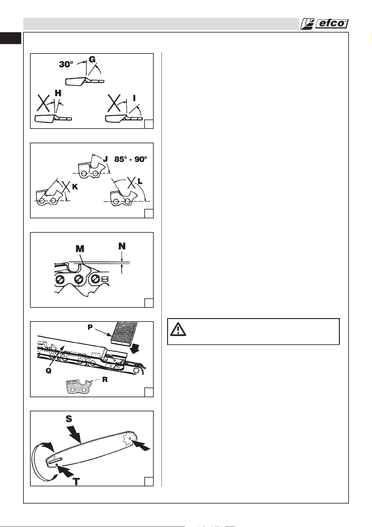
Top Plate Angle
File holders are marked with guide marks to align file properly to
produce correct TOP PLATE ANGLE (Fig. 68).
G) CORRECT- 30°
H) LESS THAN 30° - For Cross Cutting.
I) MORE THAN 30°- Feathered Edge Dulls Quickly.
Side Plate Angle (Fig. 69)
68
69
J) CORRECT- 85° - 90°
Produced automatically if correct diameter file is used in file
holder.
K) “HOOK”- “Grabs” and dulls quickly. Increases potential of
KICKBACK.
Results from using a file with diameter too small, or file held
too low.
L) BACKWARD SLOPE- Needs too much feed pressure, causes
excessive wear to bar and chain.
Results from using a file with diameter too large, or file held
too high.
Depth Gauge Clearance
1. The depth gauge (M, Fig. 70) should be maintained at a
clearance (N) between .020 (0.5 mm) and .024" (0.6 mm). Use
a depth gauge tool for checking the depth gauge clearances.
2. Every time the chain is filed, check the depth gauge
clearance.
70
71
72
Use a Flat File and a Depth Gauge Jointer to lower all gauges
uniformly (Fig. 71).
P) FLAT FILE
Q) DEPTH GAUGE JOINTER
Depth gauge jointers available in .020" to .035" (0.5mm to
0.9mm). After lowering each depth gauge, restore original
shape by rounding the front (R). Be careful not to damage
adjoining drive links with the edge of the file.
CAUTION: After sharpening, clean the chain
thoroughly, remove filings or grinding dust – lubricate
the chain thoroughly.
Guide Bar Maintenance
Every day of use, reverse the guide bar on the pole pruner to
distribute the wear for maximum bar life (see Fig. 72). The bar
should be cleaned every day of use and checked for wear and
damage.
Feathering or burring of the bar rails is a normal process of bar
wear. Such faults should be smoothed with a file or stone as soon
as they occur.
A bar with any of the following faults should be replaced:
• Wear inside the bar rails which permits the chain to lay over
sideways.
• Bent guide bar.
• Cracked or broken rails.
• Spread rails.
In addition, guide bars with a sprocket at their tip must be
lubricated periodically with a grease syringe to extend the guide
bar life. Turn the guide bar and check that the lubrication holes
(T) and chain groove (S) are free from impurities.
26
Page 27
MAINTENANCE
Carburetor Adjustment
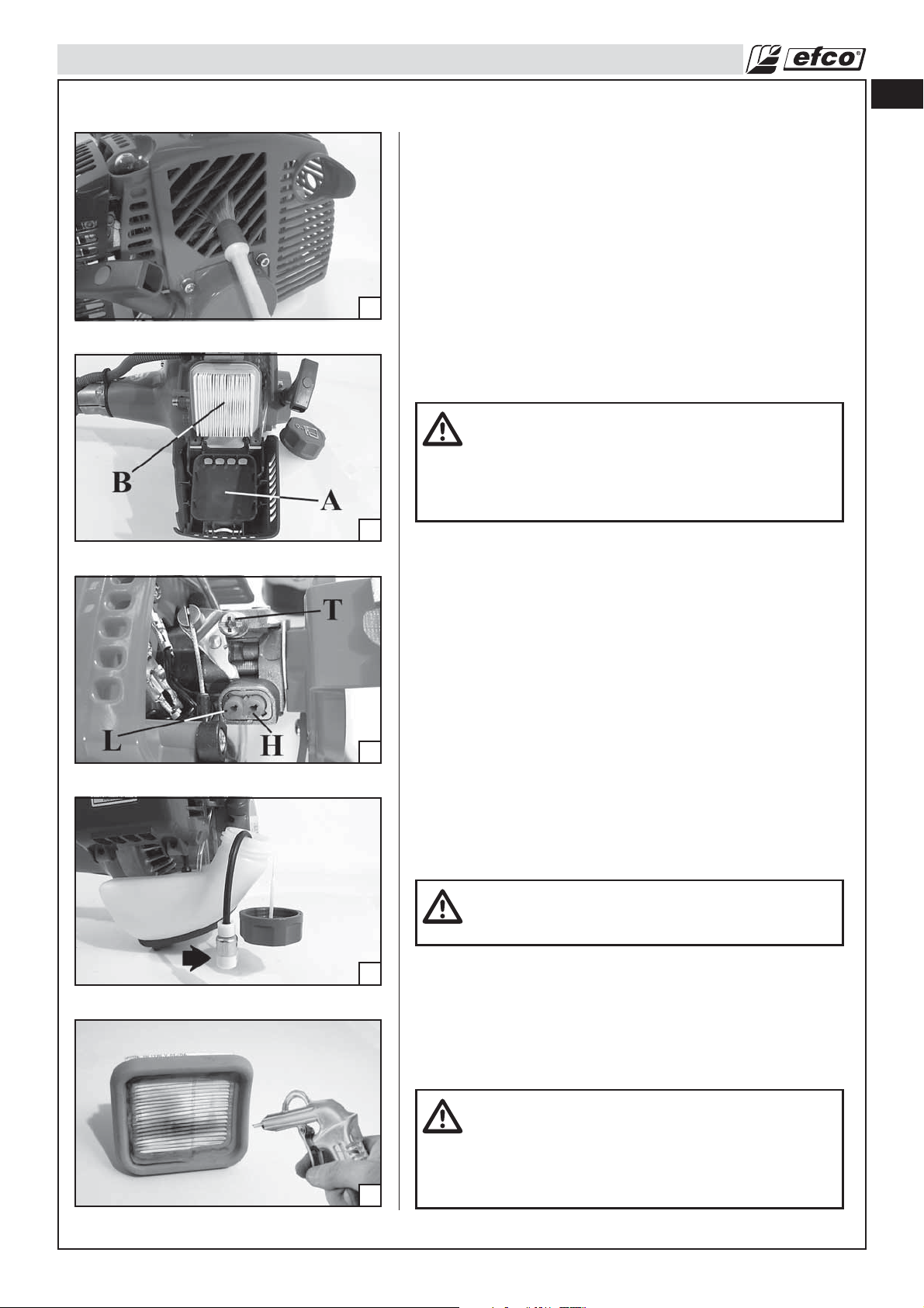
Before adjusting the carburetor, clean the starter cover vents as
shown in Illustration Fig. 73, and air filter as shown in Illustration
Fig. 74 (B), refer to Operation-Starting Unit and Maintenance-Air
Filter Sections for details. Allow the engine to warm up prior to
carburetor adjustment.
This engine is designed and manufactured in order to comply with
EPA (Environmental Protection Agency) Phase 2 regulations.
The carburetor is factory set and should not require adjusting.
73
74
The carburetor will permit only limited adjustment of the “L” (Low
Jet) and “H” (High Jet) needles (Fig. 75). Any adjustment should
be done by a Servicing Dealer.
Under no circumstances should the “L” (Low Jet) and “H” (High
Jet) needles be forced outside the range of adjustment.
en
WARNING: Serious damage can occur to the engine
if improper adjustments are made to the “L” and “H”
needles. Do not force the “L” and “H” needles
outside the adjustment range in such case the
engine will not run in compliance with emissions
regulations.
75
76
Idle Speed Adjustment
• If the engine starts, runs, and accelerates but will not idle; turn
the idle speed screw “T” clockwise to increase idle speed
(Fig. 75).
• If the chain turns at idle, turn the idle speed screw “T”
counterclockwise to reduce the idle RPM and stop the chain
movement. If the pole pruner chain still moves at idle speed,
contact a Servicing Dealer for adjustment and discontinue use
until the repair is made.
Fuel Filter
Check the fuel filter (Fig. 76) periodically. Replace it if contaminated
or damaged.
Air Filter
WARNING: Do not clean filter in gasoline or other
flammable solvent to avoid creating a fire hazard or
producing harmful evaporative emissions.
Remove air filter cover (A, Fig. 74) and check the air filter (B) each
day. Blow with compressed air, at a distance (Fig. 77). Reinstall
the air filter into cover. Place the air filter cover onto the pole
pruner. Tighten the air filter cover.
A used air filter can never be completely cleaned. It is advisable
to replace your air filter with a new one after six month of
operation.
77
CAUTION: Never run the engine without the air filter,
serious damage could result.
Make sure the air filter is correctly placed in the air
filter cover before reassembly.
Always replace damaged filters.
Do not clean a filter with a brush.
27
Page 28
en
MAINTENANCE
Starter Unit
Engine
78
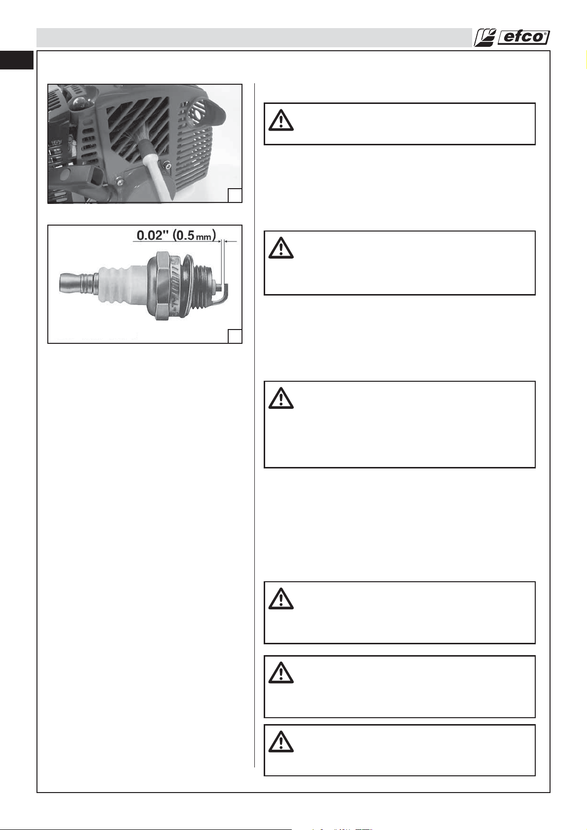
Clean the cylinder fins with compressed air or a brush periodically
(Fig. 78). Dangerous overheating of engine may occur due to
impurities on the cylinder.
WARNING: The coil spring is under tension and
could fly apart causing serious injuries. Never try to
disassembly or modify it.
WARNING: Never run the pole pruner without all the
parts, including the drivecase cover and starting
housing, securely in place. Because parts can fracture
and pose a danger of thrown objects, leave repairs to
the flywheel and clutch to trained Servicing Dealers.
CMR7A
79
Spark Plug
This engine uses a NGK CMR7A with .02” (0.5 mm) electrode gap
(Fig. 79). Use an exact replacement and replace every six months
or more frequently, if necessary.
WARNING: Never test the ignition system with
ignition wire connector removed from spark plug or
with unseated spark plug, since uncontained
sparking may cause a fire. A loose connection
between spark plug terminal and ignition wire
connector in the boot may create arcing that could
ignite combustible fumes and cause a fire.
Use only resistor type spark plugs of the approved range.
Factors such as:
- too much oil in fuel mix;
- dirty air filter;
- unfavourable running conditions, e.g. operating at part load;
may result in rapid deterioration of the spark plug.
Muffler
WARNING – This muffler incorporates a catalytic
converter, needed in order to ensure the engine
complies with current emissions standards. Never
attempt to modify or remove the catalytic converter: in
doing so, you will be breaking the law.
28
WARNING – Mufflers with catalytic converters become
very hot during operation, and retain heat for a long
time after the engine has been stopped. This is the
case even with the engine idling. Contact can burn
the skin. Always remember the potential fire risk!
CAUTION – If the catalytic converter is damaged, it
must be replaced. If the catalytic converter frequently
becomes blocked, this could be an indication that the
efficiency of the muffler is limited.
Page 29
MAINTENANCE
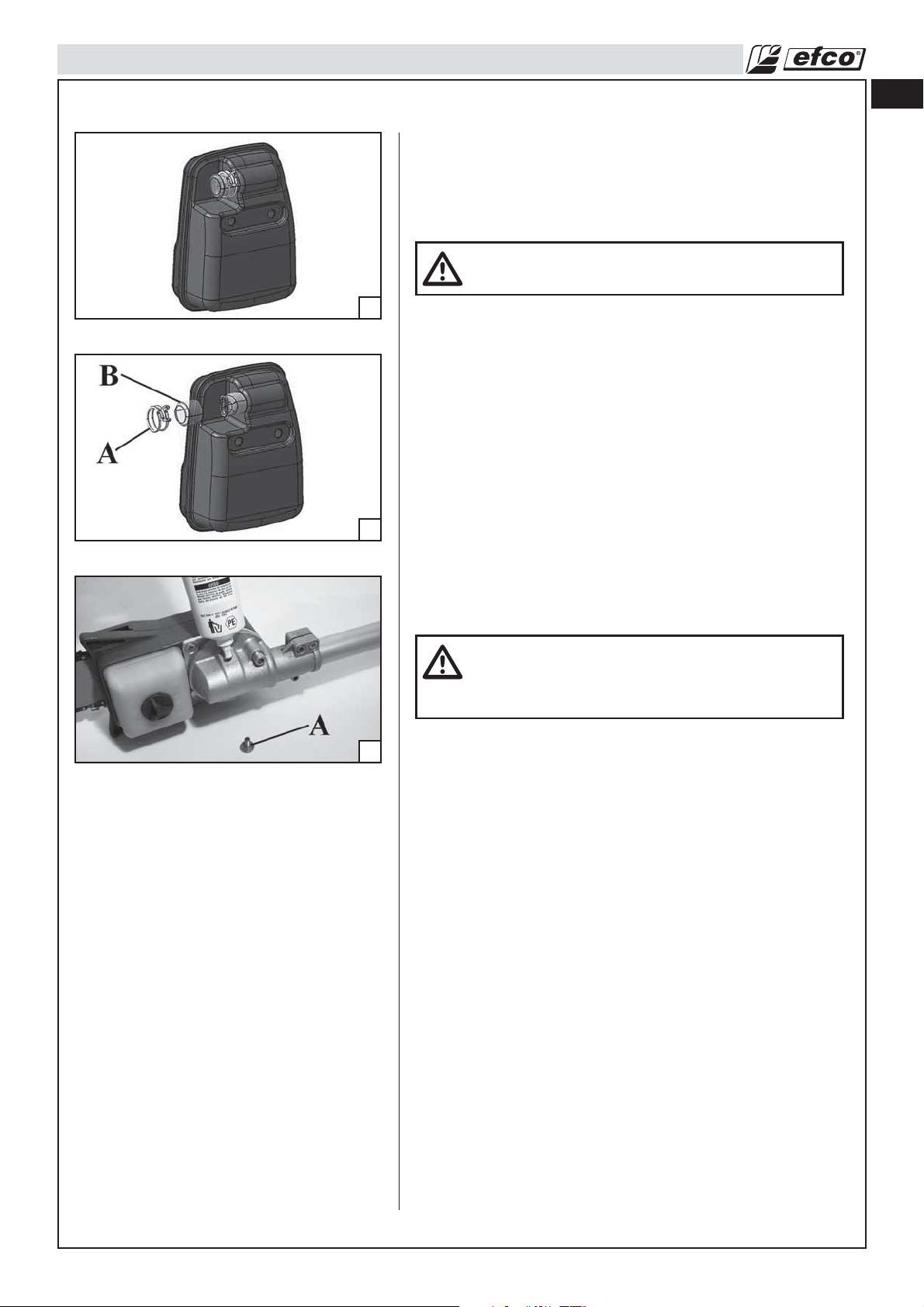
Spark Arresting Muffler
The pole pruner is provided with a Spark Arrester System
p.n. 61280087 (Fig. 80) complying with the requirements of SAE
J335 standard; you can check the p.n. of the Spark Arrester
System on the muffler itself.
WARNING: A faulty or altered spark arrester system
screen can create a fire hazard.
en
80
81
82
Through normal use the screen can become dirty and should be
inspected weekly and cleaned as required.
To clean:
• Allow the muffler to cool.
• Remove the stop spring (A, Fig. 81).
• Remove the spark arrester screen (B).
• Clean and inspect the spark arrester screen.
• Reassemble components in reversed order of removal.
The Spark Arrester System needs a periodic and accurate
maintenance and cleaning, in particular:
- check periodically the spark arrester screen and substitute it
when holes, bends or deformations appear;
- check carefully if dust, debris or organic material is in contact
with parts of the Spark Arrester System; check especially the
gap between the muffler and the shield; clean it often with
tools or shop air.
WARNING: Do not operate your pole pruner if the
muffler is damaged, missing or modified. An
improperly maintained muffler will increase the risk of
fire and hearing loss.
Gear Housing
Every 30 working hours, remove screw (A, Fig. 82) on the gear
housing and check the quantity of grease. Use high quality
molybdenum bisulfide grease.
29
Page 30

en
TROUBLESHOOTING
Using Trouble shooting Chart
WARNING: Always stop unit and disconnect spark plug before performing all of the
recommended remedies below except remedies that require operation of the unit.
When you have checked all the possible causes listed and you are still experiencing the problem, see your
Servicing Dealer. If you are experiencing a problem that is not listed in this chart, see your Servicing Dealer
for service.
PROBLEM POSSIBLE CAUSE SOLUTION
Engine will not start or will run only a
few seconds after starting.
(Make sure Ignition switch is in start
position “I”)
Engine starts but will not accelerate
properly:
Engine starts but will not run properly
at high speed.
Engine does not reach full speed and
/ or emits excessive smoke
Engine starts, runs, and accelerates
but will not idle.
Bar and Chain Running Hot and
Smoking
Engine starts and runs, but chain is
not rotating
WARNING: Never touch
the chain while the engine
is running.
1. No spark
2. Flooded engine.
Carburetor requires “L” (Low jet)
adjustment.
Carburetor requires “H” (High jet)
adjustment.
1. Check oil fuel mixture.
2. Air filter dirty.
3. Carburetor requires “H” (High jet)
adjustment.
Carburetor requires adjustment. Turn idle speed screw “T” clockwise to
1. Chain oil tank empty.
2. Chain tension too tight.
3. Oiler function.
1. Chain tension too tight.
2. Guide bar and chain assembly.
3. Chain and/or guide bar damaged.
4. Clutch drum and/or rim sprocket
damaged.
1. Check Spark. Remove air filter cover.
Remove spark plug from cylinder.
Reattach the spark plug wire and lay
spark plug on top of cylinder. Pull the
starter rope and watch for spark at
spark plug tip. If there is no spark,
repeat test with a new spark plug
(CMR7A).
2. With the ignition switch off, remove
spark plug. Move choke lever to Run
position (pushed in completely) and
pull starter cord 15 to 20 times. This
will clear excess fuel from engine.
Clean and reinstall spark plug. Pull the
choke lever all out and then insert it
completely in order to activate the
semi-acceleration device. Pull starter
three times with choke lever at run. If
engine does not start, move choke
lever to choke and repeat normal
starting procedure. If engine still fails to
start, repeat procedure with a new
spark plug.
* Contact a Servicing Dealer for
carburetor adjustment.
* Contact a Servicing Dealer for
carburetor adjustment.
1. Use fresh fuel and the correct 2-cycle
oil mix.
2. Clean per instruction in Maintenance-Air
Filter Section.
3. *Contact a Servicing Dealer for
carburetor adjustment.
increase idle speed. (If chain turns at idle,
turn idle speed screw “T” counterclockwise
to decrease speed); see OperationCarburetor Adjustment.
1. Oil tank should be filled every time
that fuel tank is filled.
2. Tension chain per instructions in
Operation-Chain Tension section.
3. Run at full throttle 15 to 30 seconds.
Stop pole pruner and check for oil
dripping from bar tip guard and guide
bar. If oil is present the chain may be
dull or bar may be damaged. If no oil
contact a Servicing Dealer.
1. Tension chain per instructions in
Operation-Chain Tension section.
2. Refer to Assembly-Assembling the
Bar and Chain Section.
3. Refer to Maintenance-Chain and/or
Maintenance-Guide Bar Section.
4. Replace if necessary - contact a
Servicing Dealer.
30
*Note: This engine complies with EPA (Environmental Protection Agency) regulations which require exhaust
emission control. As a result, the carburetor adjustment needles are equipped with plastic caps that limit the
rotation from the original factory adjustment. If your unit exhibits specific performance problems that can not be
corrected by the Trouble Shooting Section, the unit should be taken to a Servicing Dealer for repair.
Page 31

STORAGE
Storing Pole pruner
WARNING: Stop engine and allow to cool, and secure the unit before storing or transporting
in a vehicle. Store unit and fuel in an area where fuel vapors cannot reach sparks or open
flames from water heaters, electric motors or switches, furnaces, etc. Store unit with all
guards in place. Position so that any sharp object cannot accidentally cause injury to
passersby. Store the unit out of reach of children and other unauthorized persons.
1. Drain and clean the fuel tank in a well ventilated area.
2. Drain all fuel from tank into a container approved for gasoline. Run engine until it stops. This will remove all
fuel-oil mix which could become stale and leave varnish and gum in the fuel system.
3. Clean all foreign material from the pole pruner. Keep away from corrosive agents such as garden chemicals
and de-icing salts.
4. Abide by all Federal and local regulations for the safe storage and handling of gasoline. Excess fuel should
be used in other 2-cycle engine powered equipment.
CAUTION: It is important to prevent gum deposits from forming in essential fuel system parts
such as the carburetor, fuel filter, fuel hose, or fuel tank during storage. Alcohol blended fuels
(called gasohol or E10 or using ethanol, methanol) can attract moisture which leads to fuel
mixture separation and formation of acids during storage. Acidic gas can damage the
engine.
en
TECHNICAL DATA
PT 2700 - PTX 2700
ENGINE:
Displacement: 1.66 cu. in (27.2 cc)
Bore: 1.34 in (34 mm)
Stroke: 1.18 in (30 mm)
PERFORMANCE:
Idle Speed: 2,800 RPM
WOT (With Bar & Chain): 10,500 RPM
Power: 1.3 HP/1 kW (7,500 RPM)
FUEL AND OIL SYSTEMS:
Carburetor: Multi Position Diaphragm Carburetor
Fuel Tank Capacity: 19.6 oz. (580 ml)
Fuel Mix: See Operation-Fueling Section
Oil Tank Capacity: 6.12 oz. (182 ml)
Chain Lubrication: Automatic Speed Controlled Positive Displacement Pump
IGNITION SYSTEM:
Spark Plug: NGK CMR7A
Spark Plug Gap: 0.02 in. (0.5 mm)
OVERALL LENGHT MACHINE:
CHAIN:
BAR:
90"/2.3 m (PT 2700) - 102"-150"/2.6-3.8 m (PTX 2700)
3/8"x.043"
10" (25 cm)
31
Page 32

32
Page 33

INTRODUCTION
Pour un emploi correct de la perche élagueuse et pour éviter tout accident, ne
commencez pas le travail sans avoir préalablement lu ce manuel avec attention. Vous
trouverez les descriptions du fonctionnement des différents composants, ainsi que les
instructions relatives aux contrôles et aux procédures d'entretien requis.
Remarque: les illustrations et instructions présents dans ce manuel peuvent
varier en fonction des normes de chaque pays et sont sujettes à modifications
sans préavis par le fabricant.
MANUEL DE L'UTILISATEUR
Le manuel de l'utilisateur est destiné à votre propre protection. LISEZ-LE. Conservez-le
dans un endroit approprié de façon à pouvoir s'y référer au besoin. Ayez pris
connaissance des procédures avant de commencer le montage de l'unité. Une
préparation et un entretien corrects vont de paire avec de bonnes performances de la
machine et avec une sécurité optimale.
Contactez votre concessionnaire ou votre distributeur local si vous ne comprenez pas
fr
certaines des instructions délivrées par le présent manuel.
Outre les instructions relatives au fonctionnement, le présent manuel contient des
paragraphes requérant une attention particulière de votre part.
Ces paragraphes sont signalés par les symboles décrits ci-dessous:
Avertissement: présent en cas de risque d'accident, de blessure corporelle, ou de
dégâts matériels.
Mise en garde: présent en cas de risque d'endommagement de la machine ou de ses
composants.
AVERTISSEMENT : Afin de garantir un fonctionnement correct
et en toute sécurité de la perche élagueuse, il est recommandé
de toujours conserver le manuel de l'utilisateur à proximité de
la machine. Ne prêtez ou ne louez jamais votre perche
élagueuse sans fournir le présent manuel d'utilisation et
d'entretien.
AVERTISSEMENT : Seules les personnes ayant intégralement
compris le présent manuel sont habilitées à utiliser votre
perche élagueuse.
33
Page 34

SOMMAIRE
fr
IDENTIFICATION DU PRODUIT
Composants de la perche élagueuse . . . . . . . . . . . . . . . . . . . . . . . . . . . . . . . . . . . . . . . . . . . . . . 35
SÉCURITÉ
Comprendre les étiquettes de sécurité. . . . . . . . . . . . . . . . . . . . . . . . . . . . . . . . . . . . . . . . . . . . . 36
Réglementations nationales et locales . . . . . . . . . . . . . . . . . . . . . . . . . . . . . . . . . . . . . . . . . . . . . 36
RÈGLES DE SÉCURITÉ
Précautions de base . . . . . . . . . . . . . . . . . . . . . . . . . . . . . . . . . . . . . . . . . . . . . . . . . . . . . . . . . . . 38
Manipulation du carburant . . . . . . . . . . . . . . . . . . . . . . . . . . . . . . . . . . . . . . . . . . . . . . . . . . . . . . 39
Fonctionnement et sécurité . . . . . . . . . . . . . . . . . . . . . . . . . . . . . . . . . . . . . . . . . . . . . . . . . . . . . 39
Mesures de précaution pour réduire le risque de vibrations . . . . . . . . . . . . . . . . . . . . . . . . . . . . 41
Précautions d'entretien . . . . . . . . . . . . . . . . . . . . . . . . . . . . . . . . . . . . . . . . . . . . . . . . . . . . . . . . . 41
MONTAGE
Montage del'outil de coupe . . . . . . . . . . . . . . . . . . . . . . . . . . . . . . . . . . . . . . . . . . . . . . . . . . . . . 42
FONCTIONNEMENT
Preparation . . . . . . . . . . . . . . . . . . . . . . . . . . . . . . . . . . . . . . . . . . . . . . . . . . . . . . . . . . . . . . . . . . 43
Technique de coupe . . . . . . . . . . . . . . . . . . . . . . . . . . . . . . . . . . . . . . . . . . . . . . . . . . . . . . . . . . . 44
Tension de la chaîne . . . . . . . . . . . . . . . . . . . . . . . . . . . . . . . . . . . . . . . . . . . . . . . . . . . . . . . . . . . 45
Rodage de la chaîne . . . . . . . . . . . . . . . . . . . . . . . . . . . . . . . . . . . . . . . . . . . . . . . . . . . . . . . . . . . 45
Alimentation en carburant. . . . . . . . . . . . . . . . . . . . . . . . . . . . . . . . . . . . . . . . . . . . . . . . . . . . . . . 46
Système de lubrification de la chaîne. . . . . . . . . . . . . . . . . . . . . . . . . . . . . . . . . . . . . . . . . . . . . . 47
Préparation à la coupe . . . . . . . . . . . . . . . . . . . . . . . . . . . . . . . . . . . . . . . . . . . . . . . . . . . . . . . . . 48
Démarrage du moteur . . . . . . . . . . . . . . . . . . . . . . . . . . . . . . . . . . . . . . . . . . . . . . . . . . . . . . . . . . 50
Rodage du moteur . . . . . . . . . . . . . . . . . . . . . . . . . . . . . . . . . . . . . . . . . . . . . . . . . . . . . . . . . . . . 51
Arrêt du moteur . . . . . . . . . . . . . . . . . . . . . . . . . . . . . . . . . . . . . . . . . . . . . . . . . . . . . . . . . . . . . . . 52
Techniques de travail . . . . . . . . . . . . . . . . . . . . . . . . . . . . . . . . . . . . . . . . . . . . . . . . . . . . . . . . . . 52
Élagage . . . . . . . . . . . . . . . . . . . . . . . . . . . . . . . . . . . . . . . . . . . . . . . . . . . . . . . . . . . . . . . . . . . . . 53
ENTRETIEN
Tableau d'entretien . . . . . . . . . . . . . . . . . . . . . . . . . . . . . . . . . . . . . . . . . . . . . . . . . . . . . . . . . . . . 54
Montage du guide-chaîne et de la chaîne . . . . . . . . . . . . . . . . . . . . . . . . . . . . . . . . . . . . . . . . . . 55
Entretien de la chaîne . . . . . . . . . . . . . . . . . . . . . . . . . . . . . . . . . . . . . . . . . . . . . . . . . . . . . . . . . . 57
Entretien du guide-chaîne. . . . . . . . . . . . . . . . . . . . . . . . . . . . . . . . . . . . . . . . . . . . . . . . . . . . . . . 58
Réglage du carburateur . . . . . . . . . . . . . . . . . . . . . . . . . . . . . . . . . . . . . . . . . . . . . . . . . . . . . . . . 59
Filtre à carburant . . . . . . . . . . . . . . . . . . . . . . . . . . . . . . . . . . . . . . . . . . . . . . . . . . . . . . . . . . . . . . 59
Filtre à air . . . . . . . . . . . . . . . . . . . . . . . . . . . . . . . . . . . . . . . . . . . . . . . . . . . . . . . . . . . . . . . . . . . 59
Démarreur . . . . . . . . . . . . . . . . . . . . . . . . . . . . . . . . . . . . . . . . . . . . . . . . . . . . . . . . . . . . . . . . . . . 60
Moteur. . . . . . . . . . . . . . . . . . . . . . . . . . . . . . . . . . . . . . . . . . . . . . . . . . . . . . . . . . . . . . . . . . . . . . 60
Bougie . . . . . . . . . . . . . . . . . . . . . . . . . . . . . . . . . . . . . . . . . . . . . . . . . . . . . . . . . . . . . . . . . . . . . . 60
Silencieux déchappement. . . . . . . . . . . . . . . . . . . . . . . . . . . . . . . . . . . . . . . . . . . . . . . . . . . . . . . 61
Silencieux pare-étincelles . . . . . . . . . . . . . . . . . . . . . . . . . . . . . . . . . . . . . . . . . . . . . . . . . . . . . . . 61
Couple Conique . . . . . . . . . . . . . . . . . . . . . . . . . . . . . . . . . . . . . . . . . . . . . . . . . . . . . . . . . . . . . . 61
DIAGNOSTIC DES PANNES
Utilisation du tableau de diagnostic des pannes . . . . . . . . . . . . . . . . . . . . . . . . . . . . . . . . . . . . . 62
REMISAGE
Remisage de la perche élagueuse . . . . . . . . . . . . . . . . . . . . . . . . . . . . . . . . . . . . . . . . . . . . . . . . 63
CARACTÉRISTIQUES TECHNIQUES
PT 2700. . . . . . . . . . . . . . . . . . . . . . . . . . . . . . . . . . . . . . . . . . . . . . . . . . . . . . . . . . . . . . . . . . . . . 63
PTX 2700. . . . . . . . . . . . . . . . . . . . . . . . . . . . . . . . . . . . . . . . . . . . . . . . . . . . . . . . . . . . . . . . . . . . 63
34
Page 35

IDENTIFICATION DU PRODUIT
fr
Composants de le perche élagueuse
Sistème à courroie1.
Gâchette des gaz2.
Protection du silencieux d'échappement3.
Bougie4.
G5. âhette de verrouillage des gaz
Interrupteur Marche/Arrêt6.
Tuyau de trasmission7.
Bague de fixation8.
Outil de coupe EP 120 EF9.
Guide-chaîne10.
Chaîne11.
Vis de réglage de guide-chaîne12.
Poignée (PT 2700)13.
Poignée de lanceur14.
Bouchon du réservoir de carburant15.
Couvercle de filtre à air16.
Levier de l'étrangleur17.
Bouchon du réservoir d'huile18.
Cache-guide19.
Clé mixte20.
35
Page 36

fr
SÉCURITÉ
Comprendre les étiquettes de sécurité
- Ce symbole signale un
Avertissement et une Mise en
garde.
- Votre manuel contient des messages
spéciaux attirant votre attention sur
les problèmes liés à la sécurité, les
dégâts éventuels de la machine,
ainsi que des informations utiles sur
le fonctionnement et l'entretien.
VEUILLEZ LIRE TOUTES CES
INFORMATIONS AVEC ATTENTION
AFIN D'ÉVITER DE VOUS BLESSER
OU D'ENDOMMAGER LA
MACHINE.
- Portez des lunettes de sécurité,
des protège-tympans ainsi qu'un
masque de protection lorsque vous
utilisez cette machine.
- Portez des gants de protection
renforcés et antidérapants pour la
manipulation.
- Portez des chaussures ou des
bottes de sécurité équipées de
semelles antidérapantes et
coquées.
- L’appareil n’est pas conçu
pour isoler en cas de contact
avec des lignes électriques
- ATTENTION: Les surfaces risquent
d'être très chaudes.
suspendues sous tension.
Ne jamais approcher l’engin
à moins de 10 m des lignes
électriques. Personne doit
approcher à moins de 15 m.
Réglementations nationales et locales
Votre perche élagueuse est équipée d'un silencieux d'échappement à limiteur de température, d'un
pare-étincelles conformément à la directive de pratique recommandée SAE J335 et aux Codes californiens
4442 et 4443. La réglementation régissant tous les terrains forestiers et territoires gérés par les
états de Californie, Maine, Washington, Idaho, Minnesota, New Jersey et Oregon exige l'utilisation
de moteurs à combustion interne équipés de pare-étincelles. Les autres états et institutions
fédérales sont sur le point de promulguer une réglementation identique.
Si vous utilisez une perche élagueuse dans un état ou une région soumise à cette réglementation, vous
êtes légalement responsable du maintien en état de fonctionnement de ces pièces. Le non-respect de
cette réglementation constitue une violation de la loi. L'entretien du pare-étincelles est décrit dans la
section Entretien-Silencieux à pare-étincelles du présent manuel.
Remarque: pour ce qui concerne l'utilisation de perche élagueuse dans le cadre d'une exploitation
forestière, reportez-vous au Code de réglementation fédérale, Articles 1910 et 1928.
36
AVERTISSEMENT: Le système d'allumage de votre machine génère un champ
électromagnétique de très faible intensité. Il est possible de ce champ crée des
interférences sur le fonctionnement d'un stimulateur cardiaque. Afin de réduire le
risque de blessures graves, voire de mort, les personnes équipées d'un stimulateur
cardiaque sont vivement invitées à consulter leur médecin ainsi que le fabricant du
stimulateur avant d'utiliser la machine.
AVERTISSEMENT: les surfaces du silencieux deviennent très chaudes en cours de
fonctionnement et après arrêt de la perche élagueuse ; tenez-vous à distance du
silencieux. Tout contact avec le silencieux peut entraîner de graves brûlures.
Page 37

SÉCURITÉ
fr
AVERTISSEMENT : L'exposition aux vibrations générées lors de l'utilisation d'outils à
moteurs thermiques peut entraîner des lésions vasculaires ou nerveuses au niveau des
doigts, des mains et des poignets chez les personnes sujettes à des troubles de la
circulation ou à des phénomènes de tuméfactions anormaux. En outre, il a été démontré
que l'utilisation prolongée par temps froid entraînait des lésions des vaisseaux sanguins
chez les personnes saines. En cas d'apparitions de symptômes tels que des
engourdissements douleurs, pertes de force, changements de la couleur ou de la
texture de la peau ou pertes de sensation au niveau des doigts, des mains ou des
poignets, interrompez immédiatement l'utilisation de la machine et consultez un
médecin.
AVERTISSEMENT : Les vapeurs d'échappement du moteur de ce produit contiennent
des substances chimiques que l'état de Californie a reconnues à l'origine de cancers,
d'anomalies congénitales ou d'autres troubles de la reproduction. Utilisez votre perche
élagueuse en extérieur, exclusivement dans une zone bien ventilée.
37
Page 38

RÈGLES DE SÉCURITÉ
fr
50 ft
35 ft
Précautions de base
• Lisez attentivement le présent manuel jusqu'à ce que vous
ayez intégralement compris les règles de sécurité, les mesures
de précaution et les instructions relatives au fonctionnement,
et que soyez en mesure de les appliquer avant toute utilisation
de la machine.
• Limitez l'utilisation de la perche élagueuse à des utilisateurs
adultes capables de comprendre et d'appliquer les règles de
sécurité, les mesures de précaution et les instructions relatives
au fonctionnement indiquées par le présent manuel. L'utilisation
1
2
3
4
5
de la machine par des mineurs est fortement déconseillée.
• Ne manipulez et n'utilisez pas la machine lorsque vous êtes
fatigué, malade ou perturbé, ou sous l'emprise de l'alcool, de
drogues ou de médicaments. Vous devez être en bonne forme
physique et en pleine possession de vos capacités mentales.
L'utilisation d'une perche élagueuse est relativement ardue et
pénible. Si vous présentez un état susceptible d'être aggravé
par une tâche physiquement exigeante, consultez préalablement
votre médecin (Fig. 1). Soyez plus vigilant avant les périodes
de repos et en en proximité de la fin de votre tour de travail.
• Maintenez les enfants, passants et animaux à une distance
minimale de 10 mètres (35 pieds) de la zone de travail. Ne
tolérez la présence d'aucune personne ou animal à proximité
immédiate de la perche élagueuse lors du démarrage ou en
utilisation (Fig. 2).
• La plupart des accidents liés à l'utilisation d'une perche
élagueuse sont dus à une percussion de l'utilisateur par la
chaîne. Portez en permanence des équipements de sécurité
homologués lorsque vous utilisez la perche élagueuse.
Toutefois, le port de vêtements de sécurité n'élimine pas les
risques de blessures, mais il peut en réduire les effets en cas
d'accident. Demandez conseil à votre distributeur habituel
pour le choix des équipements conformes à la réglementation.
Les vêtements utilisés ne doivent en aucun cas entraver les
mouvements. Portez un vêtement anti-coupe près du corps.
La veste (Fig. 3), la salopette (Fig. 3) et les jambières sont
des équipements idéaux. Ne portez pas de vêtements,
écharpes, cravates ou bijoux susceptibles de s'accrocher au
bois ou aux buissons. Nouez les cheveux longs et protégez-les
(par exemple, à l'aide d'un foulard, d'une casquette, d'un
casque, etc.). Chaussure ou bottes de sécurité coquées et
équipées de semelles antidérapantes (Fig. 4). Portez un
casque de protection (Fig. 5) dans les zones où des objets
sont susceptibles de chuter. Portez des lunettes de
sécurité ou une visière de protection ! Utilisez des
protections anti-bruit, notamment un casque anti-bruit
(Fig. 5) ou des protège-tympans. L'utilisation de protections
anti-bruit requiert une attention supplémentaire en ce sens que
la perception des signaux sonores d'avertissement en cas de
danger (tels que cris, alarmes, etc.) est réduite. Portez des
gants anti-coupe (Fig. 6).
• Ne prêtez votre perche élagueuse qu'à des utilisateurs
expérimentés rompus au fonctionnement et à l'utilisation
corrects des perche élagueuses. Fournissez-leur le manuel
contenant le mode d'emploi qu'ils devront lire avant d'utiliser
la perche élagueuse.
• Contrôlez quotidiennement votre perche élagueuse afin de
garantir que chaque dispositif de sécurité ou autre fonctionne
correctement.
• Ne travaillez jamais avec une perche élagueuse endommagée,
modifiée ou mal réparée ou mal montée. Ne démontez,
endommagez ou neutralisez jamais l'un des dispositifs de
sécurité. Utilisez exclusivement des guide-chaîne de la
longueur indiquée dans le fabricant. Remplacez immédiatement
un guide-chaîne, cassés ou démontés pour toute autre
raison.
• Élaborez toujours votre plan de découpe à l'avance. Ne
débutez aucun tâche avant d'avoir une zone de travail
dégagée, une assise stable, et, en cas d'abattage, un chemin
de dégagement préalablement établi.
• Adressez-vous à un professionnel qualifié pour toute autre
intervention ne figurant pas dans le présent manuel.
38
Page 39

RÈGLES DE SÉCURITÉ
10 ft
• La perche élagueuse est exclusivement destinée à la coupe de
bois. Il est fortement déconseillé de couper un autre type de
matériau.
• Il est fortement déconseillé de raccorder à la prise de force de
la perche élagueuse tout outil ou accessoire non spécifié par
le fabricant.
fr
Manipulation du carburant
AVERTISSEMENT : L'essence est un carburant
6
• Manipulez le carburant avec une extrême précaution afin
• Faites le mélange et conservez le carburant dans un conteneur
• Faites le mélange de carburant en extérieur, en l'absence de
7
8
9
• Choisissez une surface dégagée, coupez le moteur et laissez
• Devissez lentement le bouchon de carburant afin de libérer la
• Resserrez fermement le bouchon de carburant après
• Essuyez toute trace de carburant sur la perche élagueuse.
• Ne tentez en aucun cas de brûler le carburant déversé.
• Ne fumez pas en manipulant le carburant ou en utilisant la
• Entreposez le carburant dans un endroit sec, frais et
• Ne placez jamais la perche élagueuse sur un matériau
• Entreposez la machine et le carburant dans un endroit exempt
• Ne retirez jamais le bouchon du réservoir de carburant lorsque
• N'utilisez jamais le carburant pour le nettoyage.
• Veillez à ne pas souiller vos vêtements de carburant.
hautement inflammable. Manipulez l'essence ou le
mélange de carburant avec une extrême précaution.
Ne fumez pas ou ne produisez pas de source de
flamme à proximité du carburant ou de la perche
élagueuse (Fig.7).
d'éviter tout risque d'incendie ou de brûlure. Le carburant
est hautement inflammable.
approuvé pour l'entreposage d'essence (Fig. 8).
toute source d'étincelles ou de flammes.
refroidir avant de faire le plein.
pression et d'empêcher le carburant de s'écouler par le
bouchon.
remplissage. Sous l'effet des vibrations de la machine, un
bouchon mal refermé peut se desserrer, voire s'ouvrir, entraînant
un déversement du carburant.
Déplacez-vous à 3 mètres (10 pieds) de la zone de remplissage
avant de démarrer le moteur (Fig. 9).
perche élagueuse.
suffisamment ventilé.
facilement inflammable, notamment sur des feuilles mortes, de
la paille, du papier, etc.
de sources d'étincelles ou de flammes nues, de moteurs
électriques, d'interrupteurs, de fours, etc., susceptibles
d'enflammer les vapeurs de carburant.
le moteur tourne.
10
Fonctionnement et sécurité
AVERTISSEMENT: Tenez toujours la perche
élagueuse à deux mains lorsque le moteur tourne.
Enserrer fermement les poignées de la perche
élagueuse entre les doigts et le pouce (Fig.10).
• Tenez toutes les parties du corps à distance de la chaîne
lorsque le moteur tourne.
• Transportez toujours la perche élagueuse moteur coupé et
frein de chaîne engagé, en plaçant le guide-chaîne et la chaîne
vers l'arrière, et le silencieux d'échappement à distance de
votre corps. Transportez toujours la perche élagueuse avec
son fourreau de guide-chaîne monté (Fig.11, page 40). Pour le
transport à bord d'un véhicule, montez toujours le fourreau de
guide et de chaîne. Fixez correctement la perche élagueuse
afin d'éviter qu'elle ne se renverse, que le carburant ne
39
Page 40

RÈGLES DE SÉCURITÉ
fr
50 ft
35 ft
11
12
13
s'écoule ou que la perche élagueuse ne soit endommagée.
• N'utilisez jamais la perche élagueuse d'une seule main !
Une telle manipulation peut blesser gravement l'utilisateur ou
les personnes se tenant dans la zone de travail. Une perche
élagueuse s'utilise à deux mains.
• Avant de démarrer le moteur, vérifiez que la chaîne n'est en
contact avec aucun objet. Ne tentez jamais de démarrer la
perche élagueuse avec le guide engagé dans un sillon de
coupe.
• Coupez le moteur avant de poser la perche élagueuse. Ne
laissez pas le moteur tourner sans surveillance.
• Utilisez exclusivement la perche élagueuse dans une zone
suffisamment ventilée, ne l'utilisez pas dans un environnement
explosif ou inflammable ou dans des zones confinées (Fig.12).
Faites attention à la possibilité d’empoisonnement par
monoxyde de carbone.
• N'utilisez pas la perche élagueuse sur une échelle ou
directement sur un arbre. Ayez toujours une assise stable et
une position appropriée.
• N'exercez pas de pression sur la perche élagueuse en fin de
coupe. Le fait d'appliquer une pression peut vous faire perdre
le contrôle en fin de coupe.
• N'effectuez aucune opération de coupe à proximité de câbles
électriques (Fig. 13).
• Tenez vos mains au sec, propres et exemptes d'huile ou de
carburant.
• Lorsque la perche élagueuse est en marche, saisissez
fermement la poignée avant de la main gauche et la poignée
arrière de la main droite. (Fig.10, page 39).
• Lors de la découpe d'une branche en tension, veillez à ne pas
vous faire surprendre par l'effet de retour élastique dès que la
tension de la fibre du bois est libérée.
• Les petites branches ou les arbustes peuvent bloquer la
chaîne puis être expulsés dans votre direction ou vous faire
perdre l'équilibre.
• Ne démarrez jamais la perche élagueuse si le carter de chaîne
n'est pas installé.
• N’utilisez pas la perche élagueuse comme levier pour lever,
déplacer ou casser quoi que ce soit.
• Entamez toujours votre coupe en mettant la pleine puissance
du moteur.
14
15
Comment garder le contrôle (Fig.14-15)
• Tenez fermement la perche élagueuse à deux mains lorsque le
moteur tourne et ne la lâchez pas. En maintenant fermement
la perche élagueuse, vous réduirez le risque de rebond et
garderez le contrôler de la machine. Saisissez la poignée
arrière de la main droite, que vous soyez droitier ou gaucher.
Votre bras gauche doit être tendu et le coude bloqué.
• Enserrez la poignée avant de la main gauche de telle façon
qu'elle soit en ligne droite avec la main droite saisissant la
poignée arrière lorsque vous effectuez une coupe de débitage.
N'inversez jamais la position des mains quel que soit le type
de coupe effectué.
• Tenez-vous sur vos deux pieds, le poids également réparti.
• Positionnez-vous légèrement sur la gauche de la perche
élagueuse de façon à éviter que votre corps soit directement
en ligne avec la chaîne.
• Ne vous penchez pas trop, sous peine de perdre l'équilibre et
le contrôle de la machine.
40
Page 41

RÈGLES DE SÉCURITÉ
Mesures de précaution pour réduire les risques liés aux vibrations
• La perche élagueuse est équipée d'un système anti-vibrations (AV) ; ne le modifiez jamais.
• Portez des gants et tenez vos mains au chaud.
• Tenez toujours la chaîne affûtée et effectuez correctement l'entretien de la perche élagueuse, notamment
le système AV. Une chaîne émoussée rallonge le temps de coupe, et le fait d'introduire une chaîne
émoussée dans une bille de bois augmente les vibrations transmises directement aux mains.
• Maintenez fermement la perche élagueuse sans pour cela "écraser" les poignées en continu; faites de
fréquentes pauses. Toutes les mesures de précautions citées ci-dessus ne garantissent pas que vous ne
souffrirez pas du syndrome des doigts morts ou canal carpien. Par conséquent, il est fortement
recommandé aux utilisateurs réguliers de surveiller l'état de leurs mains et de leurs doigts. En cas
d'apparition de l'un des symptômes précédemment cités, consultez immédiatement un médecin.
Précaution d'entretien
AVERTISSEMENT: n'utilisez jamais une perche élagueuse endommagée, mal réglée, ou
mal/partiellement montée.
• Vérifier que la chaîne s'arrête lorsque vous relâchez la gâchette des gaz. Si la chaîne se déplace au
régime de ralenti, il est peut-être nécessaire de procéder au réglage du carburateur ; Voir la section
Fonctionnement-Réglage du carburateur. Si la chaîne se déplace toujours après réglage du carburateur,
contactez un réparateur agréé pour effectuer les réglages et n'utilisez plus la machine tant que la
réparation n'a pas été effectuée.
AVERTISSEMENT : Hormis les instructions d'entretien fournies par le Manuel de
l'opérateur, toutes les autres procédures d'entretien de la perche élagueuse doivent être
effectuées par un personnel de maintenance qualifié. (En cas d'utilisation d'outils non
appropriés pour le démontage du volant-moteur ou de l'embrayage, ou pour le maintien
du volant-moteur en vue du démontage de l'embrayage, le volant-moteur peut subir des
dégâts structurels à l'origine de son éclatement pouvant causer de graves blessures).
fr
• Ne modifiez en aucune façon les caractéristiques de votre perche élagueuse.
• Tenez vos mains au sec, propres et exemptes d'huile ou de carburant.
AVERTISSEMENT: Utilisez exclusivement des accessoires et des pièces de rechange
préconisés.
• Ne touchez jamais la chaîne ou n'effectuez jamais l'entretien lorsque le moteur tourne.
• N'utilisez jamais le carburant pour le nettoyage.
• Entreposez la perche élagueuse dans un endroit sec et non directement sur le sol, avec le couvre-chaîne
monté et les réservoirs vides.
• Si votre perche élagueuse n'est plus utilisable, mettez-la au rebut de façon appropriée en respectant
l'environnement, en la retournant notamment à votre distributeur qui se chargera de sa mise au rebut
dans le respect de la réglementation.
• Remplacez immédiatement tout dispositif de sécurité endommagé ou cassé.
AVERTISSEMENT : le silencieux ainsi que d'autres pièces du moteur (notamment les
ailettes du cylindre, la bougie d'allumage) atteignent des températures très élevées en
fonctionnement et après arrêt de la machine. Afin de réduire les risques de brûlure, ne
touchez pas le silencieux ou les autres pièces lorsqu'elles sont encore chaudes.
41
Page 42

MONTAGE
fr
16
17
Montage de l’outil de coupe
Introduire le tube de transmission (A, Fig. 16) dans l’outil de
coupe (B), jusqu’à ce que l’orifice de centrage coïncide avec
celui de l’accessoire.
Fixer la vis de centrage (C, Fig. 16) puis les deux vis
(D, Fig. 17).
ATTENTION! – Avant d’utiliser l’appareil, consulter le
manuel de l’accessoire EP120 EF.
Réglage de la tige télescopique (PTX 2700)
ATTENTION! – Procéder au réglage de la tige moteur
éteint et avec la protection de la chaîne.
Desserrer la bague de fi xation (A, Fig. 18) en la tournant dans le sens
des aiguilles d’une montre. Régler la tige à la mesure nécessaire.
Serrer la bague (A, Fig. 19) en la tournant dans le sens inverse des
aiguilles d’une montre.
18
19
Réglage angulaire de l’outil de coupe (EP120 EF)
ATTENTION! – Procéder au réglage angulaire moteur
éteint et protection de chaîne montée.
Desserrer la vis (B, Fig. 20) pour modifi er l’orientation de l’outil de
coupe de 0° à 90°. L’outil dispose de trois crans intermédiaires entre
0° et 90° (22°-45°-67°) qui le bloquent sur les positions conseillées.
Resserrer la vis (B) après avoir choisi l’angle de coupe.
ATTENTION – Assurez-vous de verrouiller l'outil de
coupe dans l'un des cinq postes; de ne pas le laisser
dans une position intermédiaire.
42
20
Page 43

FONCTIONNEMENT
21
22
Preparation
LES COURROIES
Un bon réglage du système de courroies permet à la perche
élagueuse d'avoir un bon équilibre et d'être à une hauteur du sol
adéquate (Fig. 21).
- Enfi lez la courroie simple (Fig. 22).
- Accrochez la perche élagueuse à la courroie à l'aide du crochet
(A, Fig. 23).
- Placez la boucle (C, Fig. 24) de manière à ce que la perche
élagueuse soit à la bonne hauteur.
REGLES D'USAGE
- Enfi lez la courroie et gardez toujours les deux mains sur les
poignées pendant que la perche élagueuse est en marche
(Fig. 25A).
- Utilisez la perche elagueuse comme il est illustré à la
Fig. 25B.
ATTENTION: Avant d'utiliser la perche élagueuse, lisez
attentivements les régles de sécurité.
UTILISATION
fr
23
24
ATTENTION - La perche élagueuse ne doit être
utilisée que pour scier du rameau. Il est interdit
de couper d’autres matériaux. Les vibrations et
le rebond sont en effet différents et les mesures
de sécurité ne seraient pas respectées. N’utilisez
pas la perche élagueuse comme levier pour lever,
déplacer ou casser quoi que ce soit. Il est interdit
de brancher sur la prise de force de la perche
élagueuse des outils ou des applications autres que
ceux que le constructeur a indiqués.
25A 25B
43
Page 44

FONCTIONNEMENT
fr
26
27
Technique de coupe
Saisir la poignée de commande de la main droite et la tige de la
main gauche (Fig. 25A). Pour les modèles PT 2700, toujours saisir
la zone de la gaine (C, Fig. 26) de la main gauche.
Pour obtenir un équilibre parfait, tenir l’engin le plus près possible
du corps. La position la moins fatiguante s’obtient en faisant un
angle de 60° avec le terrain (Fig. 25B).
Pour faciliter la chute des branches coupées, commencer à couper
les branches par le bas.
En présence de grosses branches (plus de 10 cm de diamètre),
les couper en plusieurs tronçons (longueur maxi 20 cm) et jamais
tout entières (Fig. 27) en procédant selon la technique de la coupe
partielle.
Toujours couper à la puissance maxi.
ATTENTION! – Ne jamais rester sous la branche à
couper; tenir compte de l’espace de chute et du fait
que les morceaux peuvent rebondir sur le terrain
(Fig. 28A).
ATTENTION! – Faire très attention en travaillant
à proximité de lignes électriques aériennes. Les
branches pourraient causer un court-circuit en
tombant. Ne jamais approcher l’engin à moins de 10
m des lignes électriques (Fig. 28B).
28A 28B
29A 29B
Coupe partielle (Fig. 29A) – Pour éviter d’écorcer la branche, de
recevoir un contre-coup ou de bloquer la barre, procéder à une
coupe partielle sur la partie inférieure des grosses branches (1).
Passer ensuite au sciage (2).
Coupes particulières (PTX 2700)
Le grand rayon d’action de la perche élagueuse télescopique
permet de:
- couper des branches au-delà de certains obstacles (Fig. 29B),
par exemple, au-dessus des étangs, etc...
- couper des branches plus confortablement à partir d’une plateforme de levage (Fig. 30).
44
30
Page 45

FONCTIONNEMENT
.050" (1.25 mm)
31
32
33
Tension de la chaîne
AVERTISSEMENT: Ne touchez ou ne réglez jamais la
chaîne alors que le moteur tourne. La chaîne est
extrêmement affûtée ; portez en permanence des
gants de protection lorsque vous effectuez l'entretien
de la chaîne.
1. Coupez le moteur avant de procéder au réglage de la
tension de chaîne. Desserrez légèrement les écrous de
guide-chaîne, tournez la vis de tension de chaîne dans le
sens des aiguilles d'une montre pour tendre la chaîne. Voir
la section Montage-Montage du guide-chaîne et de la chaîne.
Resserrez les écrous de guide-chaîne. Une chaîne à froid est
tendue correctement lorsque la partie inférieure du guidechaîne ne présent aucun jeu; la chaîne est relativement serrée
mais peut être tournée à la main sans contrainte.
Reportez-vous au paragraphe 3 pour ce qui concerne une
chaîne chaude.
2. La chaîne doit être tendue lorsque les méplats (A) sur les
tenons des maillons-guides sortent de la rainure du
guide-chaîne. Voir Fig. 31.
3. En fonctionnement normal, la température de la chaîne
augmente. Les tenons des maillons-guides d'une chaîne
tendue correctement doivent dépasser d'environ 1,25 mm de
la rainure du guide-chaîne. Voir Fig. 32. Afin de déterminer la
tension correcte d'une chaîne chaude, il est possible d'utiliser
l'extrémité d'une clé mixte (Fig. 33) comme indicateur.
fr
34
35
MISE EN GARDE: Une chaîne tendue alors qu'elle
est chaude peut être trop serrée lorsqu'elle refroidit.
Contrôlez la "tension à froid" avant une utilisation
ultérieure.
MISE EN GARDE: Une chaîne neuve doit être
retendue plus fréquemment qu'une chaîne déjà
utilisée à plusieurs reprises.
Rodage de la chaîne
Les chaînes neuves ont tendance à s'étirer et doivent être
tendues fréquemment. Soulevez la chaîne hors de la rainure du
guide-chaîne et lubrifiez la rainure (Voir Fig. 34). Placez la perche
élagueuse sur un morceau de carton ou de contreplaqué.
Démarrez la perche élagueuse (Voir la section FonctionnementDémarrage du moteur) et laissez-le tourner à régime modéré
pendant une (1) minute environ. Coupez le moteur. Contrôlez le
bon fonctionnement de la pompe à huile. Le morceau de carton
doit recueillir l'excès d'huile de la chaîne en rotation si la pompe
à huile fonctionne correctement (Voir Fig. 35). Réglez la tension
de chaîne (Voir la section Fonctionnement-Tension de chaîne).
Redémarrez la perche élagueuse et effectuez quelques coupes
sur un rondin de façon à chauffer la chaîne. Coupez le moteur et
réglez à nouveau la chaîne. Répétez cette procédure jusqu'à ce
que la chaîne conserve un réglage de tension à chaud correct,
comme indiqué dans la Fig. 32 de la section FonctionnementTension de la chaîne. Ne touchez jamais le sol avec la chaîne.
45
Page 46

FONCTIONNEMENT
fr
36
37
Alimentation en carburant (Interdiction de fumer!)
(Fig. 38)
Ce produit est équipé d'un moteur deux temps et nécessite un
mélange préalable d'essence et d'huile pour moteurs deux
temps. Effectuez le mélange d'essence sans plomb et d'huile
pour moteur deux temps dans un conteneur propre et adapté
pour l'essence (Fig. 36).
CARBURANT RECOMMANDÉ: CE MOTEUR EST CERTIFIÉ
POUR FONCTIONNER AVEC DE L'ESSENCE SANS PLOMB
POUR USAGE AUTOMOBILE PRÉSENTANT UN INDICE
D'OCTANE DE 89 ([R + M] / 2) OU SUPÉRIEUR (Fig. 37).
Mélangez l'huile pour moteur deux temps à l'essence
conformément aux instructions fournies sur l'étiquette. Il est
vivement recommandé d’utiliser 2 % (1:50) d’huile Efco pour
moteurs deux temps, car cette huile est spécialement formulée
pour tous les moteurs Efco à deux temps à refroidissement par
air.
Les proportions d’huile / de carburant indiquées dans le tableau
ci-dessous conviennent en cas d’utilisation de l’huile Efco pour
moteurs deux temps ou d’une autre huile moteur de haute qualité
équivalente (JASO FD ou ISO L-EGD).
Si l’huile utilisée présente des spécifications NON équivalentes
ou inconnues, la proportion du mélange huile / carburant doit être
de 4 % (1:25).
MISE EN GARDE: N'UTILISEZ PAS D'HUILE POUR
AUTOMOBILE OU D'HUILE POUR MOTEUR DEUX
TEMPS DE HORS-BORD.
38
MISE EN GARDE: N'utilisez jamais de carburant dont
le taux d'alcool est supérieur à 10 % ; l'essence-alcool
jusqu'à 10 % ou le carburant E10 sont acceptables.
Une bonne pratique de la gestion des carburants est nécessaire
lors de l'utilisation d'essence oxygénée.
L'essence oxygénée avec de l'alcool retire facilement l'eau
lorsqu'elle est présente; cette eau peut se condenser dans l'air
humide et contaminer le circuit d'alimentation de carburant,
réservoir inclus.
MISE EN GARDE:
- Adaptez vos achats de carburant à votre
consommation; n'en achetez pas plus que vous
en consommerez en un ou deux mois;
- Entreposez l'essence dans un conteneur
hermétique et dans un endroit se et frais.
L'utilisation d'essence oxygénée peut faciliter le phénomène de
formation de tampon de vapeur.
46
Page 47

FONCTIONNEMENT
10 ft
39
40
REMARQUE: L'huile pour moteurs deux temps contient un
stabilisateur de carburant et peut être conservée pendant 30
jours. NE MÉLANGEZ PAS plus de carburant que vous pourrez
en utiliser sur une période de 30 jours. L'utilisation d'une huile
deux temps contenant un stabilisateur de carburant est
recommandée.
Mélange de carburant
Huile pour moteurs deux temps (25:1) 4%
Essence Huile
1 Gallon (US) . . . . . . . . . . . . . . . . . . . . . . . . . . . 5.2 oz.
1 Litre . . . . . . . . . . . . . . . . . . . . . . . . . . . . . . . . . 40 cc (40 ml)
Haute qualité huile pour moteurs deux temps (50:1) 2%
Essence Huile
1 Gallon (US) . . . . . . . . . . . . . . . . . . . . . . . . . . . 2.6 oz.
1 Litre . . . . . . . . . . . . . . . . . . . . . . . . . . . . . . . . . 20 cc (40 ml)
Remplissage du réservoir (Fig. 40)
AVERTISSEMENT: Respectez les mesures de
sécurité pour la manipulation du carburant. Coupez
toujours le moteur avant d'approvisionner la machine
en carburant. Ne faites jamais l'appoint de carburant
alors que le moteur tourne ou s'il est encore chaud.
Déplacez-vous à au moins 3 mètres (10 pieds) de la
zone de remplissage avant de démarrer le moteur
(Fig. 39). NE FUMEZ PAS !
fr
41
1. Nettoyez la surface autour du bouchon de carburant afin
d'éviter toute contamination.
2. Dévissez lentement le bouchon de carburant.
3. Versez le mélange de carburant dans le réservoir avec
précaution. Évitez de renverser du carburant.
4. Avant de remonter le bouchon de carburant, nettoyez et
inspectez le joint d'étanchéité.
5. Remontez et serrez immédiatement le bouchon de carburant.
Essuyez tout déversement de carburant.
REMARQUE: Lors de sa première utilisation, un moteur émet
une certaine quantité de fumée. Cela est normal.
AVERTISSEMENT: Contrôlez la présence éventuelle
de fuites de carburant, et rectifiez le cas échéant.
Contactez un réparateur agréé si nécessaire.
Système de lubrification de la chaîne (Fig. 41)
Le guide-chaîne et la chaîne doivent être lubrifiés en permanence.
Cette lubrification s'effectue par le biais d'un dispositif de
graissage automatique lorsque le réservoir d'huile est plein. Un
manque d'huile endommagera très rapidement le guide et la
chaîne. Une trop faible quantité d'huile entraîne une surchauffe
matérialisée par un échappement de fumée au niveau de la
chaîne et/ou une décoloration du guide-chaîne. Par temps très
froid, l'huile a tendance à s'épaissir, ce qui rend nécessaire
l'utilisation d'une petite proportion (5 à 10 %) de carburant diesel
ou de kérosène pour diluer l'huile du guide et de la chaîne. L'huile
de guide et de chaîne doit être non-agglomérante de façon à ce
que le circuit d'huile puisse pomper une quantité suffisante
d'huile pour garantir une lubrification adéquate.
47
Page 48

FONCTIONNEMENT
fr
42
43
MISE EN GARDE: N'utilisez jamais d'huile usagée !
Utilisez toujours un lubrifiant biodégradable
spécifique pour guide-chaîne et chaîne, qui respecte
davantage l'environnement et protège les pièces de
la perche élagueuse.
AVERTISSEMENT: N'utilisez pas d'huiles sales,
usagées ou contaminées. Cela pourrait endommager
la pompe à huile, le guide ou la chaîne.
AVERTISSEMENT: N'utilisez pas d'huile usagée! Des
essais médicaux ont démontré qu'un contact répété
avec de l'huile usagée peut être à l'origine de
cancers de la peau.
1. Faites le plein d'huile à chaque plein de carburant. La perche
élagueuse consomme approximativement un plein d'huile par
plein de carburant.
2. La pompe à huile automatique est une pompe volumétrique
actionnée par pignons entraînés par l'ensemble tambour
d'embrayage. La pompe ne fournit aucun graissage lorsque le
moteur est au ralenti.
Préparation à la coupe
Prise correcte des poignées.
Reportez-vous à la section Sécurité pour ce qui concerne
d'équipement de sécurité approprié.
1. Portez des gants antidérapants pour une adhérence et une
protection optimales.
AVERTISSEMENT: Tenez fermement la perche
élagueuse à deux mains. Tenez toujours la poignée
avant de la MAIN GAUCHE et la poignée arrière
(accélérateur) de la MAIN DROITE, comme indiqué
dans la Fig.42, de telle façon à placer votre corps sur
la gauche du plan de rotation de la chaîne. Ne
croisez jamais les mains, ou n'adoptez aucune
position qui placerait votre corps ou vos bras dans
le plan de rotation de la chaîne. Ces directives
s'appliquent également aux gauchers.
2. Gardez une bonne prise en main de la machine lorsque le
moteur tourne. Les doigts doivent venir enserrer la poignée.
Toute position de la main qui placerait les doigts et le pouce
du même côté de la poignée est dangereuse dans la mesure
où un léger a-coup de la perche élagueuse peut entraîner une
perte de contrôle.
AVERTISSEMENT:
Position correcte de coupe (Fig. 43)
- Le poids doit être équitablement réparti sur les
deux pieds reposant sur un sol stable.
- Le corps doit toujours se tenir à gauche du plan
de rotation de la chaîne.
48
Page 49

FONCTIONNEMENT
50 ft
35 ft
44
Méthode de coupe de base
Exercez-vous sur quelques rondins de faible diamètre en utilisant
la technique suivante afin de vous "familiariser" avec la prise en
main de votre perche élagueuse avant de débuter des travaux de
coupe plus conséquents.
1. Adoptez la position appropriée face à la bille de bois avec la
perche élagueuse tournant au ralenti.
2. Accélérez jusqu'au régime moteur maximal en appuyant sur la
gâchette des gaz avant d'enfoncer la chaîne dans la bille de
bois.
3. Maintenez le régime moteur maximal pendant toute la durée
de la coupe.
4. Laissez la chaîne agir; n'exercez qu'une faible pression vers le
bas. Le fait de forcer la coupe peut endommager le guide, la
chaîne ou le moteur.
5. Relâcher la gâchette des gaz dès que la coupe est terminée,
et laissez tourner le moteur au ralenti. Le guide, la chaîne ou
le moteur peuvent subir une usure inutile voire des dégâts
si vous faites tourner le moteur à plein régime sans aucune
charge de coupe.
6. N'appliquez aucun pression sur la perche élagueuse en fin de
coupe.
Précautions relatives à la zone de travail
AVERTISSEMENT: Ne coupez que du bois ou des
matériaux dérivés du bois. Ne coupez ni métaux, ni
plastiques, ni pièces de maçonnerie ou tout autre
matériau qui ne serait pas dérivé du bois.
fr
• Ne laissez jamais un enfant utiliser la perche élagueuse. Toute
autre personne susceptible d'utiliser la perche élagueuse doit
avoir préalablement lu le présent Manuel de l'opérateur ou
avoir pris connaissance des instructions appropriées à une
utilisation correcte et en toute sécurité de cette perche
élagueuse.
• Maintenez toute personne - assistant, entourage, enfants et
animaux - à une distance de sécurité de la zone de coupe
(Fig. 44).
• Gardez en permanence les deux pieds sur une assise stable
de façon à éviter toute perte d'équilibre.
• Ne coupez pas en dessus dans la hauteur de poitrine, car il est
toujours plus difficile de contrôler une perche élagueuse
placée en hauteur en cas de rebond.
• Ne travailler à proximité de lignes électriques ou de
constructions. Laissez agir des professionnels dans de pareilles
situations.
• Ne procédez à des travaux de coupe que si la visibilité et la
luminosité vous permettent d'y voir clairement.
• N'utilisez pas la perche élagueuse sur une échelle.
• Arrêtez la perche élagueuse si la chaîne heurte un corps
étranger. Inspectez la perche élagueuse et effectuez les
réparations si nécessaire.
• Éliminez la poussière et le sable déposés sur la perche
élagueuse. Même une très faible quantité de crasse peut très
rapidement émousser une chaîne et augmenter le risque de
rebond.
• Coupez le moteur avant de reposer la perche élagueuse.
• Soyez particulièrement vigilant lorsque vous portez des
protections anti-bruit car de tels équipements réduisent la
capacité d'entendre les signaux sonores d'avertissement en
cas de danger (tels que cris, alarmes et avertissements, etc.).
• Soyez extrêmement vigilant lorsque vous travaillez en pente
ou sur des surfaces irrégulières.
49
Page 50

FONCTIONNEMENT
fr
45
46
Démarrage du moteur
AVERTISSEMENT: Placez votre corps à gauche du
plan de rotation de la chaîne. Ne vous tenez jamais les
deux jambes écartées de part et d'autre de la perche
élagueuse ou de la chaîne, ou ne vous penchez jamais
au-delà du plan de rotation de la chaîne.
• Ne faites pas démarrer le moteur sans que le bras soit monté.
• Posez la perche élagueuse sur un sol de niveau et vérifiez
qu'aucun objet ou obstacle n'est en contact immédiat avec le
guide ou la chaîne. Maintenez le corps de la machine vers le
sol avec votre main gauche (ATTENTION! Jamais avec le
pied!), voir Fig.45.
• Remplir le carburateur en agissant sur la pompe (A, Fig. 40).
• Tirez le levier de l'accélérateur (B) et mettez l'interrupteur
(A, Fig.47) sur (
relâ-chez le levier (B).
• Mettez le levier starter (D, Fig.48) sur CLOSE.
• En tenant la perche élagueuse tirez lentement la cordelette
dedémarrage jusqu'à ce que vous sentiez une ceratine résistance
(Fig.45). Tirez énergiquement plusieurs fois et auxpremières
détonations du moteur remettez le levier du starter (D, Fig. 49)
dans sa position d'origine OPEN. Répétez cette manœuvre de
démarrage jusqu'à ce que le moteur parte.
• Une fois parti appuyez sur l'accélérateur (B, Fig.47) afin qu'il
sorte de sa position de demi-accélération et faites tournerle
moteur au ralenti.
) pour bloquer en demi-accélération; puis
47
48
ATTENTION: Quand le moteur est chaud n'utilisezpas
le starter pour le faire démarrer.
ATTENTION: N'utilisez le dispositif demi-accélération
que dans la phase de démarrage du moteur à froid.
• En cas de mise en marche à chaud du moteur, l’interrupteur (F)
doit être positionné comme il est indiqué sur la Fig.49.
AVERTISSEMENT: Ne procédez pas à la coupe alors
que le levier d'étrangleur/ralenti accéléré est en position
d'étranglement maximal (FULL CHOKE). N'utilisez pas
votre perche élagueuse alors que le blocage
d'accélérateur appliqué. Le fait de travailler avec le
blocage d'accélérateur de démarrage engagé ne permet
pas à l'utilisateur de contrôler correctement le régime
de la perche élagueuse ou la vitesse de la chaîne.
REMARQUE - DÉMARRAGE D'UN MOTEUR CHAUD:
Suivez les instructions pour le démarrage mais n'utilisez pas
la position d'étranglement maximal pour redémarrer un
moteur. Pour régler passer la machine au ralenti accéléré
pour le démarrage d'un moteur chaud, tirez complètement le
levier d'étrangleur et ramenez-le en position initiale de
fonctionnement.
50
49
AVERTISSEMENT: Les conditions climatiques et
l'altitude peuvent affecter la carburation. Tenez les
tierces personnes à distance de la perche élagueuse
lors du réglage du carburateur.
Page 51

FONCTIONNEMENT
51
AVERTISSEMENT: Ne tentez jamais de démarrer
votre perche élagueuse lorsque le guide-chaîne est
engagé dans une entaille de coupe ou un trait
d'abattage.
ATTENTION – Ne jamais mettre la perche élagueuse
en marche si la barre, la chaîne et le carter du
pignon ne sont pas montés – l'embrayage pourrait
se détendre ce qui pourrait mettre l'opérateur en
danger (risque de blessures).
Rodage du moteur
Le moteur atteint sa puissance maximale après 5 à 8 heures de
fonctionnement. Au cours de cette période de rodage, ne laissez
pas tourner la machine à vide à plein régime de façon à éviter toute
contrainte inutile.
MISE EN GARDE ! – Au cours de la période de rodage,
ne modifiez pas la carburation sous prétexte
d'obtenir une augmentation de la puissance; vous
risquez uniquement d'endommager le moteur.
Démarrage difficile (ou démarrage d'un moteur noyé)
Vous pouvez noyer le moteur par une alimentation en carburant
trop importante si le moteur ne démarre pas après avoir actionné
10 fois le lanceur. Il est possible d'éliminer l'excès de carburant
d'un moteur noyé en suivant la procédure de démarrage d'un
moteur chaud décrite ci-dessus. Vérifiez que 'interrupteur de
marche/arrêt est en position de marche (ON). Le démarrage peut
nécessiter un grand nombre d'actionnements du lanceur en
fonction de l'importance du noyage du moteur. Si vous ne
parvenez pas à démarrer le moteur, reportez-vous au TABLEAU
DE DIAGNOSTIC DES PANNES (page 62).
fr
Moteur noyé
Si vous n'avez pas passé le levier d'étrangleur en position de
démarrage à chaud assez rapidement après le début d'allumage
du moteur, la chambre de combustion est noyée.
• Basculez l'interrupteur de marche/arrêt sur la position STOP.
• Insérez un outil adapté dans la coiffe de bougie (Fig. 51).
• Faites levier sur la coiffe de bougie et retirez-la.
• Dévissez et séchez la bougie.
• Ouvrez l'accélérateur à fond.
• Actionnez le lanceur à plusieurs reprises de façon à vider la
chambre de combustion.
• Remontez la bougie et connectez la coiffe en l'enfonçant
fermement – Remontez les autres pièces.
• Basculer l'interrupteur de marche/arrêt sur I, la position de
démarrage.
• Passez le levier d'étrangleur sur la position de démarrage à
chaud – même si le moteur est froid.
• Démarrez à présent le moteur.
51
Page 52

FONCTIONNEMENT
fr
Arrêt du moteur
Relâchez la gâchette des gaz (B, Fig. 52) et laissez le moteur
tourner au ralenti.
Pour couper le moteur, basculez l'interrupteurde marche/arrêt (A)
sur la position STOP. Ne reposez pas ladébroussailleuse tant que
l'outil de coupe est encore enmouvement.
Au cas où la position STOP de l'interrupteur ne fonctionnerait
pas, coupez le moteur en ramenant le levier d'étrangleur sur la
position FERMER (CLOSE) (Fig.48).
52
MISE EN GARDE: La chaîne se rétracte en
refroidissant. Si elle n'est pas détendue, elle peut
endommager le arbre du pignon et les roulements.
Contrôle avant utilisation
AVERTISSEMENT: LA CHAÎNE NE DOIT JAMAIS
TOURNER LORSQUE LE MOTEUR EST AU RÉGIME
DE RALENTI. Tournez la vis de réglage du ralenti “T”
dans le sens inverse des aiguilles d'une montre pour
réduire le régime de ralenti et arrêter la rotation de
la chaîne, ou contactez un réparateur agréé pour
procéder au réglage; n'utilisez pas la machine avant
que la réparation n'ait été effectuée.
Le fait que la chaîne tourne au régime de ralenti peut
être à l'origine de graves blessures.
CHARGE
Première entaille
jusq'à un tiers du
diamètre
Coupe Finale
Deuxième coupe
53
Techniques de Travail
Conditions tchniques de travail dangereuses particulières
AVERTISSEMENT: Ne travailler par grand vent ou
par fortes précipitations.
AVERTISSEMENT: N'effectuez jamais à un travail de
coupe par faible visibilité ou par températures
extrêmement élevées ou basses, ou par grandes
gelées.
AVERTISSEMENT: Ne travailler à proximité de lignes
électriques ou de constructions. Avisez
immédiatement le fournisseur d'électricité en cas
de contact entre la ligne de service public.
AVERTISSEMENT: Vérifiez la présence éventuelle de
branches mortes ou endommagées susceptibles de
chuter et de vous heurter au cours de travail.
• Élaborez toujours votre plan de travail à l'avance.
• Dégagez la zone de travail. Une zone dégagée est nécessaire
tout autour de l'arbre de façon à ce que vous ayez une bonne
assise.
Recherchez toute trace de pourriture. Si le branche est pourri, il
peut casser net et chuter en direction de l'opérateur.
Assurez-vous de disposer de l'espace nécessaire pour la chute
de le branche. Tenez toute autre personne ou objet à une distance
de deux fois et demi la hauteur de l'arbre. Le bruit du moteur peut
couvrir un cri d'alerte. Retirez les obstacles, pierres, écorce
décrochée, clous, agrafes et fils métalliques de l'arbre à l'endroit
de la coupe.
Choisissez votre voie de retraite (ou vos voies de retraite si l'une
d'entre elle est bloquée). Dégagez la zone à proximité immédiate
de l'arbre et vérifiez qu'il n'y a aucun obstacle entravant votre
voie de retraite.
52
Page 53

FONCTIONNEMENT
AVERTISSEMENT: Ne retournez jamais la perche élagueuse pour le débitage par le bas. Il n'est pas
possible de contrôler la perche élagueuse dans une telle position. Effectuez toujours la première
entaille de débitage sur le souche en compression. Le souche en compression correspond à la zone
où se concentre la pression du souche.
Élagage
• Méfiez-vous de l'effet de retour élastique. Prenez garde aux branches pliées ou sous pression. Évitez d'être heurté
par la branche ou la perche élagueuse au moment où la tension des fibres du bois est relâchée.
• Maintenez la zone de travail dégagée. Évacuez fréquemment les branches afin d'éviter de trébucher contre elles.
AVERTISSEMENT : Ne grimpez jamais sur un arbre pour effectuer l'ébranchage ou l'élagage. Ne vous
tenez pas sur une échelle, ou un rondin, ou dans toute position susceptible de vous faire perdre
l'équilibre et le contrôle de la perche élagueuse.
Opération d'élagage (Fig. 53)
• Pour l'élagage, il est important de ne pas effectuez la coupe à ras à proximité de la branche maîtresse ou du tronc
avant d'avoir coupé une partie de la branche de façon à réduire le poids. Cela permet d'éviter d'arracher l'écorce
au niveau du membre principal.
• Coupez tout d'abord le premier tiers de la branche par le bas, puis le restant de la branche par le haut de façon à
faire tomber la branche.
• Vous pouvez à présent passer à la finition en procédant à la coupe à ras du membre principal soigneusement et
proprement, de telle sorte que l'écorce recouvrira la cicatrice.
fr
53
Page 54

ENTRETIEN
fr
Veuillez noter que les intervalles d'entretien suivant s'appliquent exclusivement à une utilisation
en conditions normales. Rapprochez ces intervalles en conséquence si votre travail quotidien
implique un fonctionnement plus long dans des conditions de coupe sévères.
Intégralité de la perche élagueuse
Commandes (Interrupteur d'allumage, levier d'étrangleur,
gâchette des gaz, gâchette de blocage des gaz)
Réservoir de carburant
Réservoir d'huile
Filtre à carburant Inspection
Lubrification de la chaîne Contrôle de la sortie
Chaîne
Guide-chaîne Inspection (dégâts et niveau d'usure)
Pignon à flasques Inspection (dégâts et niveau d'usure)
Tambour d'embrayage Inspection (dégâts et niveau d'usure)
Attrape-chaîne Inspection (dégâts et niveau d'usure)
Toute la visserie accessible (sauf vis de réglage) Inspect
Filtre à air Nettoyage
Ailettes de cylindre Nettoyage
Prises d'air du système de démarrage Nettoyage
Corde de lanceur Inspection (dégâts et niveau d'usure)
Carburateur
Bougie
Tableau d'entretien
Inspection (fuites, craquelures et niveau d'usure)
Nettoyage
Contrôle du fonctionnement
Inspection (fuites, craquelures et niveau d'usure)
Nettoyage
Inspection (fuites, craquelures et niveau d'usure)
Nettoyage
Nettoyage, remplacement de la cartouche
filtrante
Inspection (dégâts, affûtage et niveau d'usure)
Contrôle de la tension
Affûtage (Contrôle de l'indicateur de profondeur)
Nettoyage de la rainure du guide et des passages d'huile
Rotation
Graissage du pignon de renvoi
Ébavurage
Remplacement
Remplacement
Remplacement
Retighten
Remplacement
Remplacement
Contrôle du ralenti (la chaîne ne doit pas tourner au régime de ralenti)
Contrôle de l'écartement entre les électrodes
Remplacement
mois
utilisation
arrêt pour
Avant chaque
XX
XX
XX
XX
XX
XX
XX
XX
X
XX
X
XX
XX
ravitaillement
Après chaque
X
X
semaine
Une fois par
après le travail
Quotidiennement
X
X
X
X
X
X
X
X
Une fois par
Si endommagée
X
X
X
XX
XX
X
XX
X
X
X
X
X
Selon besoins
ou défectueuse
Tous les
6 mois
Remplacer
par la nouvelle
chaîne
Tous les
6 mois
Tous les
6 mois
54
Page 55

ENTRETIEN
55
56
Montage du guide-chaîne et de la chaîne
AVERTISSEMENT: Contrôlez fréquemment la tension de la chaîne lorsque vous utilisez la perche
élagueuse. Ne touchez ou ne réglez jamais la chaîne
lorsque le moteur tourne. La chaîne est extrêmement affûtée; portez en permanence des gants de
protection lorsque vous effectuez l'entretien de la
chaîne.
1. Retirez les deux (2) écrous de guide-chaîne (A, Fig. 55) et le
couvercle (B).
2. Réglez la goupille de tension de chaîne (C) à fond vers la
protection en tournant la vis de tension de chaîne (D) dans le
sens inverse des aiguilles d'une montre comme indiqué dans
l'insert de la Fig. 56.
3. Le guide-chaîne (E, Fig. 57) st équipé d'une fente dans
laquelle se montent les goujons pour guide-chaîne (F). Il est
également équipé de deux orifices pour la goupille de tension
de chaîne (G) et de deux orifices de graissage, un de chaque
côté. Le guide-chaîne est réversible et l'un ou l'autre orifice
pour goupille de tension de chaîne peut être utilisé
indifféremment.
4. Monter le guide-chaîne (E) sur les goujons (F) comme indiqué
dans la Fig. 57.
5. Insérer le guide-chaîne (E) dans la boucle de chaîne (H)
comme indiqué dans la Fig. 58. Les gouges sur la partie
supérieure du guide-chaîne doivent être orientées vers
l'extrémité avant du guide, dans le sens de rotation de la
chaîne. Voir l'insert (L) de la Fig. 59.
6. Passer la chaîne (H, Fig. 58) sur le pignon à flasques (M) puis
dans la rainure du guide-chaîne.
fr
57
58
59
MISE EN GARDE: Le pignon à flasques, le tambour
d'embrayage, le guide-chaîne et la chaîne peuvent
être sérieusement endommagés sir la chaîne n'est
pas correctement insérée dans le pignon à flasques.
7. Remontez le couvercle (B). Tournez la vis de tension de chaîne
(D) dans le sens des aiguilles d'une montre jusqu'à ce que la
goupille de tension de chaîne (C) se loge dans l'orifice de
goupille de tension de chaîne (G). Montez les deux écrous de
guide-chaîne (A). Serrez-les à la main. Le guide-chaîne doit
pouvoir se déplacer librement pour le réglage de la tension.
MISE EN GARDE: La perche élagueuse subira de
graves dégâts lors du remontage du couvercle du
pignon si la goupille de tension de chaîne n'est pas
correctement logée dans l'orifice de goupille de
tension de chaîne.
8. Éliminez tout jeu au niveau de la chaîne en tournant la vis de
tension de chaîne (D) dans le sens des aiguilles d'une montre,
en vérifiant que la chaîne est bien logée dans la rainure du
guide-chaîne lors du réglage de la tension.
9. Soulevez la partie supérieure du guide-chaîne pour vérifier le
jeu (Voir Fig. 60). Relâchez la partie supérieure du guide-chaîne
et tourner la vis de tension de chaîne (D) d'un demi-tour dans
le sens des aiguilles d'une montre. Répétez cette procédure
jusqu'à suppression de tout jeu.
55
Page 56

ENTRETIEN
fr
60
61
10. Maintenez l'extrémité du guide-chaîne et serrez les écrous de
guide (A) comme indiqué dans la Fig. 55.
11. La chaîne est tendue correctement lorsque la partie inférieure
du guide-chaîne ne présent aucun jeu; la chaîne est
relativement serrée mais peut être tournée à la main sans
contrainte (Voir Fig. 61).
REMARQUE: Si la chaîne est montée trop serrée, elle ne
pourra tourner. Desserrez légèrement les écrous de
guide-chaîne et tournez la vis de réglage d'un quart de tour
dans le sens inverse des aiguilles d'une montre. Soulevez
l'extrémité du guide-chaîne et resserrez les écrous.
AVERTISSEMENT: Si la perche élagueuse est utilisée
avec une chaîne détendue, celle-ci peut échapper
du guide-chaîne et entraîner de graves blessures.
AVERTISSEMENT: Ne démarrez jamais la perche
élagueuse alors que le couvercle de pignon est
desserré.
56
Page 57

ENTRETIEN
Plaque
supérieure
Trou de rivet
Talon
Queue
d'entraînement
Creux de la gouge
Parties de la gouge
Plaque
latérale
Limiteur de
profondeur
Pointe
62
63
64
65
Entretien de la chaîne
Pour obtenir une coupe rapide et en souplesse, il est nécessaire
d'entretenir correctement la chaîne à limiteur d'épaisseur. Cette
chaîne nécessite un affûtage lorsque les copeaux de bois sont
petits ou pulvérulents, lorsqu'il est nécessaire d'exercer une force
sur la bille de bois pour enfoncer la chaîne, ou lorsque la chaîne
coupe sur le côté. Prenez en compte les éléments suivants pour
l'entretien de votre chaîne:
1. Un angle d'attaque frontale incorrecte de la plaque latérale
peut accroître le risque d'un important effet de rebond.
2. Épaisseur du copeau (limiteur de profondeur) (A, Fig. 62): Trop
importante, augmente le risque de rebond ; insuffisante, réduit
la capacité de coupe.
3. Si les gouges ont heurté des objets durs tels que des clous ou
des pierres, ou si elles ont été élimées par de la boue ou du
sable présent dans le bois, faites affûter la chaîne par un
service d'entretien agréé.
4. Dans de rares circonstances, les tenons d'entraînement
peuvent s'évaser, empêchant la chaîne de tourner librement.
Remplacez la chaîne si nécessaire.
REMARQUE: Inspectez l'état et le niveau d'usure du pignon à
flasques lors du remplacement de la chaîne. En cas de signes
d'usure ou d'endommagements au niveau des zones indiquées
dans la Fig.63, faites remplacer le pignon à flasques par un
réparateur agréé.
Affûtage des gouges (Fig.64)
Veillez à affûter toutes les gouges aux angles spécifiés et à la
même longueur, car la caractéristique de coupe rapide ne peut
être assurée que si toutes les gouges sont uniformes.
1. Portez des gants de protection. Tendez suffisamment la chaîne
de sorte qu'elle n'oscille pas. Procédez à l'affûtage au niveau
du centre du guide-chaîne. Voir la section FonctionnementTension de la chaîne.
2. Utilisez une lime ronde de diamètre 5/32" (4 mm) et un portelime.
3. Tenez la lime de niveau avec la plaque supérieure de la dent,
comme indiqué dans la Fig. 65. Ne laissez pas la lime plonger
ou osciller.
4. En exerçant une pression légère mais ferme, limez en direction
du coin avant de la dent, comme indiqué dans la Fig. 66.
Soulevez la lime de la gouge à chaque retour de lime.
5 Mettez quelques fermes coups de limes sur toute la dent.
Limez toutes les gouges dont le tranchant est situé côté
gauche (E, Fig. 67) dans un seul sens. Passez ensuite aux
gouges dont le tranchant se situe côté droit et limez (F) dans
le sens opposé. Éliminez de temps en temps les copeaux de
la lime à l'aide d'une brosse métallique.
fr
66
67
MISE EN GARDE: Une chaîne émoussée ou mal
affûtée peut entraîner un régime excessif du moteur
lors de la coupe, et sévèrement endommager le
moteur.
AVERTISSEMENT: Le respect des angles et des
dimensions spécifiés ci-dessous et absolument
essentiel. Si la chaîne est mal affûtée, et tout
particulièrement si le limiteur d'épaisseur est trop
profond, le risque de rebond est accrû, ainsi que le
risque de blessures.
Le fait de ne pas remplacer ou réparer une chaîne
endommagée peut être à l'origine de graves
blessures.
La chaîne est extrêmement affûtée; portez en
permanence des gants de protection lorsque vous
effectuez l'entretien de la chaîne.
57
Page 58

ENTRETIEN
fr
68
69
Angle des plaques supérieures
Les porte-lime sont équipés de repères permettant d'aligner
correctement la lime afin d'obtenir l'ANGLE DE PLAQUE
SUPÉRIEURE correct (Fig. 68).
G) CORRECT- 30°
H) INFÉRIEUR À 30° - Pour débitage.
I) SUPÉRIEUR À 30°- Bord aminci, émoussage rapide.
Angle des plaques latérales (Fig.69)
J) CORRECT- 85° - 90°
Obtenu automatiquement lors de l'utilisation d'une lime de
diamètre correct dans un porte-lime.
K) “CROCHET”- "Broutage" et émoussage rapide. Augmente le
risque de REBOND.
Provient de l'utilisation d'une lime de diamètre insuffisant, ou
d'une lime tenue trop bas.
L) DÉCLIVITÉ VERS L'ARRIÈRE- Nécessite un effort
d'avancement trop important et entraîne une usure excessive
du guide et de la chaîne.
Provient de l'utilisation d'une lime de diamètre trop important,
ou d'une lime tenue trop haut.
Réglage du limiteur d'épaisseur
1. La hauteur (N, Fig. 70) du limiteur d'épaisseur (M) doit être
comprise entre 0,5 mm (0,020 po.) et 0,6 mm (0,024 po.).
Utilisez une cale d'épaisseur pour contrôler la hauteur des
limiteurs d'épaisseur.
2. Contrôlez la hauteur des limiteurs d'épaisseur à chaque
affûtage de la chaîne.
70
71
72
Utilisez une lime plate et une dégauchisseuse pour limiteur
d'épaisseur pour rabaisser uniformément tous les limiteurs
(Fig.71).
P) LIME PLATE
Q) DÉGAUCHISSEUSE POUR LIMITEURS D'ÉPAISSEUR
Les dégauchisseuses pour limiteurs d'épaisseur sont
disponibles en dimensions 0,5 mm à 0,9 mm (0,020 à 0,035
pouce). Après avoir rabaissé la hauteur de chacun des
limiteurs d'épaisseur, restituez la forme initiale en arrondissant
l'avant (R). Veillez à ne pas endommager les maillons-guides
adjacents avec le bord de la lime.
MISE EN GARDE: Après affûtage, nettoyez
soigneusement la chaîne, éliminez les copeaux de
limage ou la poussière de rectification. Lubrifiez
soigneusement la chaîne.
Entretien du guide-chaîne
Après chaque journée d'utilisation, retournez le guide-chaîne sur
la perche élagueuse de façon à répartir équitablement l'usure et
rallonger la durée de vie du guide-chaîne (voir Fig. 72). Nettoyez
le guide-chaîne quotidiennement en fin de journée de travail et
contrôlez son état et son niveau d'usure.
L'amincissement ou l'écrasement au niveau des rails du guide est
un processus normal d'usure du guide-chaîne. De tels défauts
doivent être rectifiés à la lime ou à la pierre dès qu'ils apparaissent.
Remplacez le guide-chaîne s'il présente les défauts suivants:
• Usure à l'intérieur des rails du guide-chaîne laissant passer la
chaîne de chaque côté.
• Guide-chaîne tordu.
• Rails fendillés ou cassés.
58
Page 59

ENTRETIEN
73
74
• Rails étirés.
En outre, les guide-chaîne équipés d'un pignon en leur pointe
doivent être lubrifiés périodiquement à l'aide d'une seringue à
huile afin de rallonger leur durée de vie.
Retournez le guide-chaîne et vérifiez que les orifices de lubrification
(T) et la gorge de chaîne (S) sont exempts d'impuretés.
Réglage du carburateur
Avant de procéder au réglage du carburateur, nettoyez les ouïes
d'aération du couvercle de démarreur comme indiqué dans la
Fig. 73, ainsi que le filtre à air comme indiqué dans la Fig. 74 (B).
Reportez-vous aux sections Fonctionnement-Démarrage de la
machine et Entretien-Filtre à air pour de plus amples détails. Laissez
chauffer le moteur avant de procéder au réglage du carburateur.
Ce moteur est conçu et fabriqué conformément aux
réglementations de Phase 2 de l'EPA (Agence de protection de
l'environnement). Le carburateur est réglé en usine et ne
nécessite normalement aucun réglage. Ce modèle de carburateur
ne permet que le réglage des aiguilles “L” (gicleur bas) et “H”
(gicleur haut) (Fig. 75). Tout réglage doit être effectué par un
service d'entretien agréé.
Ne forcez en aucun cas les aiguilles “L” (gicleur bas) et “H”
(gicleur haut) hors de leur plage de réglage.
AVERTISSEMENT: Un réglage incorrect des aiguilles
“L” et “H” peut entraîner de graves dégâts au niveau
du moteur. Ne forcez pas les aiguilles “L” et “H” hors
de leur plage de réglage sous peine de rendre le
moteur non conforme à la réglementation relative
aux émissions polluantes.
fr
75
76
77
Réglage du ralenti
• Si le moteur démarre, tourne et accélère mais ne tient pas le
ralenti, tournez la vis de réglage du ralenti “T” dans le sens des
aiguilles d'une montre pour augmenter le ralenti (Fig. 75).
• Si la chaîne tourne au régime de ralenti, tournez la vis de
réglage du ralenti “T” ans le sens inverse des aiguilles d'une
montre pour réduire le régime de ralenti et stopper la rotation
de la chaîne. Si la chaîne continuer à tourner au régime de
ralenti, contactez un service d'entretien agréé pour procéder
au réglage et n'utilisez pas la machine tant que la réparation
n'a pas été effectuée.
Filtre à carburant
Contrôlez le filtre à carburant (Fig. 76) périodiquement.
Remplacez-le s'il est contaminé ou endommagé.
Filtre à air
AVERTISSEMENT: Ne nettoyez pas le filtre à air à
l'essence ou avec tout autre produit inflammable
afin d'éviter tout risque d'incendie ou de générer
des vapeurs nocives.
Déposez le couvercle du filtre à air (A, Fig. 74) et contrôlez le
filtre à air (B) quotidiennement. Souffler avec de l'air comprimé à
une certaine distance, de l'intérieur vers l'extérieur (Fig. 77).
59
Page 60

ENTRETIEN
fr
Remontez le filtre à air dans le couvercle. Posez le couvercle de
filtre à air sur la perche élagueuse. Resserrez fermement le
couvercle de filtre à air.
Un filtre à air usagé ne peut jamais être complètement nettoyé.
Il est recommandé de remplacer le filtre à air après six mois
d'utilisation.
MISE EN GARDE: Ne faites jamais tourner le moteur
sans le filtre à air au risque de l'endommager.
Vérifiez que le filtre à air est correctement logé dans
le couvercle de filtre à air avant procéder au
remontage de l'ensemble.
Remplacez toujours un filtre à air endommagé.
Ne nettoyez pas le filtre à l'aide d'une brosse.
Démarreur
AVERTISSEMENT: Le ressort à enroulement est
sous tension et peut "sauter" à tout moment,
entraînant de graves blessures. Ne tentez jamais de
le démonter ou de le modifier.
Moteur
Nettoyez périodiquement les ailettes du moteur à l'air comprimé
ou à l'aide d'une brosse (Fig. 78). Les impuretés incrustées sur le
cylindre peuvent entraîner une surchauffe dangereuse du
moteur.
CMR7A
78
79
AVERTISSEMENT: Ne faites jamais fonctionner la
perche élagueuse si toutes les pièces ne sont pas
correctement montées, notamment le couvercle du
carter d'entraînement et le carter du démarreur.
Dans la mesure où les pièces peuvent se casser et
voler en éclat, faites réparer le volant-moteur et
l'embrayage à un réparateur agréé.
Bougie
Ce moteur utilise une bougie NGK CMR7A avec un espacement
entre les électrodes de 0,5 mm (0,02 pouce) (Fig. 79). Remplacezla par une bougie identique tous les six mois ou plus fréquemment
si nécessaire.
AVERTISSEMENT: Ne testez jamais le système
d'allumage alors que le connecteur du câble
d'allumage est débranché de la bougie ou si la
bougie n'est pas montée dans son logement, au
risque de produire un jaillissement d'étincelles non
contrôlé qui peut entraîner un risque d'incendie. Une
mauvaise connexion entre la borne de la bougie et
le connecteur du câble d'allumage au niveau de la
coiffe peut générer un arc électrique susceptible
d'enflammer les vapeurs de carburant à l'origine
d'un incendie.
Utilisez exclusivement des bougies antiparasites de la gamme
préconisée.
Les facteurs tels que:
- un excès d'huile dans le mélange de carburant;
- un filtre à air encrassé;
- des conditions de fonctionnement défavorables, notamment le
fonctionnement en charge partielle;
peuvent entraîner une détérioration rapide de la bougie.
60
Page 61

ENTRETIEN
80
81
Silencieux d'échappement
ATTENTION – Ce pot d'échappement est doté d'un
catalyseur ce qui assure au moteur la conformité
aux conditions sur les émissions requises. Ne jamais
modifier ni déposer le catalyseur : tout modification
est une violation à la loi.
ATTENTION – Les pots d'échappement dotés
de catalyseur deviennent très chauds durant
l’utilisation et restent ainsi longtemps après avoir
éteint le moteur. Cette situation se présente même
lorsque le moteur tourne au ralenti. Vous risquez
de vous brûler en le touchant. Risque d’incendie!
PRÉCAUTION – Si le catalyseur est endommagé
il doit être remplacé. S'il se bouche fréquemment,
le rendement du pot d'échappement catalytique
s'en trouve réduit.
Silencieux pare-étincelles
Votre perche élagueuse est équipée d'un dispositif pare-étincelles
Réf. 61280087 (Fig. 80) conforme aux exigences de la norme
SAE J335; vous avez la possibilité de vérifier le numéro de
référence du dispositif pare-étincelles apposé sur le silencieux.
fr
82
AVERTISSEMENT: Un dispositif pare-étincelles
défectueux ou modifié peut être à l'origine d'un
incendie.
En usage normal, ce dispositif peut s'encrasser et doit être
contrôlé toutes les semaines et nettoyé en fonction de son état.
Pour procéder au nettoyage:
• Laissez refroidir le silencieux.
• Retirez le printemps entrprise (A, Fig. 81).
• Déposez l'écran pare-étincelles (B).
• Nettoyez et contrôlez l'écran pare-étincelles.
• Remontez les composants dans l'ordre inverse de la dépose.
Le dispositif pare-étincelles nécessite un entretien et un
nettoyage périodiques et précis, notamment pour ce qui
concerne les points suivants:
- contrôlez périodiquement l'écran pare-étincelles et remplacezle s'il est perforé, tordu ou déformé;
- vérifiez minutieusement si de la poussière, des débris ou toute
substance organique est en contact avec les pièces du
dispositif pare-étincelles; contrôlez particulièrement l'espace
entre le silencieux et l'écran; nettoyez-le souvent à l'aide
d'otuils ou à l'air comprimé.
AVERTISSEMENT: N'utilisez jamais votre perche
élagueuse si le silencieux est endommagé, déposé
ou modifié. Un silencieux mal entretenu augment le
risque d'incendie et de perte auditive.
Couple Conique
Toutes les 30 heures de travail, ôtez la vis (A, Fig. 82) sur le
couple conique et contrôlez le niveau de graisse.
Utilisez de la graisse de qualité au bisulfure de molybdène.
61
Page 62

fr
DIAGNOSTIC DES PANNES
Utilisation du tableau de diagnostic des pannes
AVERTISSEMENT: Arrêtez toujours la machine et déconnectez la bougie avant de mettre en
application l'un des remèdes préconisés ci-dessous, à l'exception des opérations nécessitant
que la machine tourne.
Si le problème persiste après avoir vérifié toutes les causes possibles indiquées, contactez votre réparateur
agréé. En cas de problème non référencé dans ce tableau, contactez votre réparateur agréé.
PROBLÈME CAUSE POSSIBLE REMÈDE
Le moteur ne démarre pas ou il tourne
pendant quelques secondes puis
s'arrête.
(Vérifiez que l'interrupteur d'allumage
est sur la position de démarrage “I”).
Le moteur démarre mais n'accélère pas
correctement:
Le moteur démarre mais ne fonctionne
pas correctement à régime élevé.
Le moteur n'atteint pas son régime
maximal / ou fume excessivement
Le moteur démarre, tourne et accélère,
mais ne tient pas le ralenti.
Surchauffe et dégagement de fumée au
niveau du guide et de la chaîne.
Le moteur démarre et tourne, mais la
chaîne n'est pas entraînée
AVERTISSEMENT: Ne touchez
jamais la chaîne lorsque le
moteur tourne.
*Remarque: Ce moteur est conforme aux normes de l'EPA (Agence de protection de l'environnement) en matière de contrôle
des émissions polluantes. En conséquence, les aiguilles de réglage du carburateur sont équipées de capuchons en plastique
limitant la rotation par rapport au réglage d'usine initial. Si votre machine présente des problèmes spécifiques de performance
ne pouvant être rectifiés en suivant les instructions de la section Diagnostic des pannes, il est recommandé la porter à un service
d'entretien agréé pour réparation.
1. Absence d'étincelle.
2. Moteur noyé.
Le carburateur nécessite un réglage de
l'aiguille “L” (gicleur bas).
Le carburateur nécessite un réglage de
l'aiguille “H” (gicleur haut).
1. Contrôlez le mélange huile/carburant.
2. Filtre à air encrassé.
3. Le carburateur nécessite un réglage de
l'aiguille “H” (gicleur haut).
Le carburateur nécessite un réglage. Tournez la vis de réglage du ralenti “T” dans le
1. Réservoir d'huile de chaîne vide.
2. Chaîne trop tendue.
3. Fonction du dispositif de graissage.
1. Chaîne trop tendue.
2. Montage du guide-chaîne et chaîne.
3. Chaîne et/ou guide-chaîne
endommagés.
4. Embrayage et/ou pignon à flasques
endommagés.
1. Contrôlez la bougie. Déposez le couvercle de
filtre à air. Retirez la bougie du cylindre.
Reconnectez le fil de bougie et placez la
bougie sur le haut du cylindre. Tirez sur le
lanceur et observez la formation d'étincelles
à l'extrémité de la bougie. Si aucune étincelle
n'est produite, répéter l'essai en utilisant une
bougie neuve (CMR7A).
2. Passez l'interrupteur d'allumage en position
d'arrêt (OFF) et retirez la bougie. Passez le
levier d'étrangleur sur la position de
fonctionnement (complètement enfoncé) et
actionnez le lanceur 15 à 20 fois. Cela
permet d'évacuer l'excès de carburant dans
le moteur. Nettoyez et remontez la bougie.
Tirer le levier du starter jusqu’au bout et
ramener le levier complètement pour activer
le dispositif de demi accélération. Actionnez
le lanceur trois fois en mettant le levier
d'étrangleur en position de fonctionnement.
Si le moteur ne démarre pas, passez le levier
d'étrangleur sur la position de démarrage et
effectuez la procédure de démarrage normal.
Si le moteur ne démarre toujours pas, répétez
la procédure avec une bougie neuve.
* Contactez un service d'entretien agréé pour
le réglage du carburateur.
* Contactez un service d'entretien agréé pour
le réglage du carburateur.
1. Utilisez du carburant récent et la proportion
d'huile deux temps appropriée.
2. Procédez au nettoyage conformément aux
instructions de la section Entretien-Filtre à air.
3. *Contactez un service d'entretien agréé pour
le réglage du carburateur.
sens des aiguilles d'une montre pour augmenter
le régime de ralenti. (Si la chaîne tourne au
régime de ralenti, tournez la vis de ralenti “T”
dans le sens inverse des aiguilles d'une montre
pour réduire le régime de ralenti); voir la section
Fonctionnement-Réglage du carburateur.
1. Le réservoir d'huile doit être rempli à chaque
plein du réservoir de carburant.
2. Tendez la chaîne conformément aux
instructions de la section FonctionnementTension de la chaîne.
3. Faites tourner le moteur à plein régime
pendant 15 à 30 secondes. Arrêtez la perche
élagueuse et vérifiez que l'huile s'écoule au
niveau de la protection d'embout de guide et
du guide-chaîne. Si l'huile est présente, il se
peut que la chaîne soit émoussée ou que le
guide-chaîne soit endommagé. En cas
d'absence d'huile, contactez un service
d'entretien agréé.
1. Tendez la chaîne conformément aux
instructions de la section FonctionnementTension de la chaîne.
2. Voir la section Montage-Montage du guidechaîne et de la chaîne.
3. Voir la section Entretien-Chaîne et/ou
Entretien-Guide-chaîne.
4. Procédez au remplacement si nécessaire Contactez un réparateur agréé.
62
Page 63

REMISAGE
Remisage de la perche élagueuse
AVERTISSEMENT: Coupez le moteur et laissez-le refroidir, puis arrimez la machine avant
remisage ou transport dans un véhicule. Remisez la machine et le carburant dans un endroit
où les vapeurs de carburant ne seront en contact avec aucune source d'étincelles ou de
flammes nues, notamment à proximité de chaudières, de moteurs ou d'interrupteurs
électriques, de fours, etc. Montez toutes les protections fournies avec la machine pour le
remisage. Rangez la machine de telle sorte que les parties tranchantes ne puissent blesser
accidentellement toute personne passant à proximité. Remisez la machine hors de portée
des enfants ou de toute autre personne non habilitée à l'utiliser.
1. Vidangez et nettoyez le réservoir de carburant dans un lieu suffisamment aéré.
2. Vidangez l'intégralité du carburant dans un conteneur approprié au stockage de l'essence. Faites tourner le
moteur jusqu'à ce qu'il s'arrête de lui-même. Cela permet d'évacuer le mélange susceptible de s'éventer et
de laisser un dépôt de vernis et de gomme dans le circuit d'alimentation de carburant.
3. Nettoyez toutes les substances étrangères accumulées sur la perche élagueuse. Maintenez la machine à
distance de tout agent corrosif tels que les engrais de jardin ou les sels de déverglaçage.
4. Respectez la réglementation locale et nationale en matière de stockage et de manipulation de l'essence.
N'utilisez pas le surplus de carburant dans un autre équipement à moteur deux temps.
MISE EN GARDE: Il est important d'éviter le dépôt de gomme dans les composants du circuit
d'alimentation de carburant tels que le carburateur, le filtre à carburant, la conduite
d'alimentation de carburant ou le réservoir de carburant au cours du remisage. Les carburants
à base d'alcool (appelés essence-alcool ou E10, ou à base d'éthanol ou de méthanol) sont
hydrophiles, ce qui peut entraîner une séparation des composants du carburant et la
formation d'acides au cours du remisage. Les gaz acides peuvent endommager le moteur.
fr
CARACTÉRISTIQUES TECHNIQUES
PT 2700 - PTX 2700
MOTEUR:
Cylindrée: 1.66 cu. in (27.2 cc)
Alésage: 1.34 in (34 mm)
Course: 1.18 in (30 mm)
PERFORMANCES:
Régime de ralenti: 2,800 RPM
Régime maximal (Avec guide et chaîne)
Puissance: 1.3 HP/1 kW (7,500 RPM)
CIRCUITS D'ALIMENTATION DE CARBURANT ET D'HUILE:
Carburateur:
Capacité du réservoir de carburant
Proportions du mélange:
Capacité du réservoir d'huile
Lubrification de la chaîne:
SYSTÈME D'ALLUMAGE:
Bougie: NGK CMR7A
Écartement des électrodes: 0.02 in. (0.5 mm)
: 10,500 RPM
Carburateur à diaphragme toute position
: 19.6 oz. (580 ml)
Voir la section Fonctionnement-Alimentation de carburant
: 6.12 oz. (182 ml)
Pompe à huile volumétrique automatique
LONGUER HORS MACHINE:
CHAÎNE:
GUIDE:
90"/2.3 m (PT 2700) - 102"-150"/2.6-3.8 m (PTX 2700)
3/8"x.043"
10" (25 cm)
63
Page 64

64
Page 65

INTRODUCCIÓN
Para utilizar correctamente la podadora y evitar accidentes, lea primero este manual
atentamente antes de trabajar con ella. Encontrará explicaciones sobre el funcionamiento
de los distintos componentes, además de instrucciones para realizar las comprobaciones
y el mantenimiento necesarios.
Nota: Las ilustraciones y las especificaciones proporcionadas en este manual
pueden variar según los requisitos de cada país, y están sujetas a cambios sin
previo aviso por parte del fabricante.
MANUAL DEL OPERADOR
El manual del operador está destinado a proporcionar protección al usuario. LÉALO.
Guárdelo en un sitio seguro para consultarlo en el futuro. Conozca los procedimientos
necesarios antes de comenzar a montar la unidad. La preparación y el mantenimiento
adecuados juegan un papel fundamental para obtener la máxima seguridad y
rendimiento del podadora.
Póngase en contacto con el concesionario o el distribuidor local si no comprende
alguna de las instrucciones de este manual.
Además de las instrucciones de uso, este manual contiene párrafos que requieren una
es
especial atención.
Tales párrafos están marcados con los símbolos descritos a continuación:
Advertencia: si existe riesgo de accidente o lesiones personales o daños graves a la
propiedad.
Precaución: si existe riesgo de producirse daños en la máquina o en sus componentes
individuales.
ADVERTENCIA: Para garantizar el funcionamiento seguro y
correcto de la podadora, este manual del operador deberá
conservarse siempre con la máquina o estar cerca de ella. No
preste ni alquile la podadora sin el manual de instrucciones
del operador.
ADVERTENCIA: Sólo deberán utilizar la podadora las personas
que entiendan este manual.
65
Page 66

es
ÍNDICE DE CONTENIDOS
IDENTIFICACIÓN DEL PRODUCTO
Componentes de la podadora . . . . . . . . . . . . . . . . . . . . . . . . . . . . . . . . . . . . . . . . . . . . . . . . . . . 67
SEGURIDAD
Significado de las etiquetas de seguridad . . . . . . . . . . . . . . . . . . . . . . . . . . . . . . . . . . . . . . . . . . 68
Requisitos estatales y locales. . . . . . . . . . . . . . . . . . . . . . . . . . . . . . . . . . . . . . . . . . . . . . . . . . . . 68
REGLAS DE SEGURIDAD
Precauciones básicas de seguridad . . . . . . . . . . . . . . . . . . . . . . . . . . . . . . . . . . . . . . . . . . . . . . . 70
Manejo del combustible . . . . . . . . . . . . . . . . . . . . . . . . . . . . . . . . . . . . . . . . . . . . . . . . . . . . . . . . 71
Funcionamiento y seguridad. . . . . . . . . . . . . . . . . . . . . . . . . . . . . . . . . . . . . . . . . . . . . . . . . . . . . 71
Precauciones para reducir el riesgo de vibraciones. . . . . . . . . . . . . . . . . . . . . . . . . . . . . . . . . . . 73
Precauciones de mantenimiento . . . . . . . . . . . . . . . . . . . . . . . . . . . . . . . . . . . . . . . . . . . . . . . . . 73
ENSAMBLAJE
Montaje de equipo de corte . . . . . . . . . . . . . . . . . . . . . . . . . . . . . . . . . . . . . . . . . . . . . . . . . . . . . 74
FUNCIONAMIENTO
Preparativos . . . . . . . . . . . . . . . . . . . . . . . . . . . . . . . . . . . . . . . . . . . . . . . . . . . . . . . . . . . . . . . . . 75
Técnica de trabajo . . . . . . . . . . . . . . . . . . . . . . . . . . . . . . . . . . . . . . . . . . . . . . . . . . . . . . . . . . . . 76
Tensión de la cadena . . . . . . . . . . . . . . . . . . . . . . . . . . . . . . . . . . . . . . . . . . . . . . . . . . . . . . . . . . 77
Rodaje de la cadena . . . . . . . . . . . . . . . . . . . . . . . . . . . . . . . . . . . . . . . . . . . . . . . . . . . . . . . . . . . 77
Alimentación de combustible . . . . . . . . . . . . . . . . . . . . . . . . . . . . . . . . . . . . . . . . . . . . . . . . . . . . 78
Sistema de lubricación de la cadena . . . . . . . . . . . . . . . . . . . . . . . . . . . . . . . . . . . . . . . . . . . . . . 79
Preparación para cortar . . . . . . . . . . . . . . . . . . . . . . . . . . . . . . . . . . . . . . . . . . . . . . . . . . . . . . . . 80
Arranque del motor . . . . . . . . . . . . . . . . . . . . . . . . . . . . . . . . . . . . . . . . . . . . . . . . . . . . . . . . . . . . 82
Rodaje del motor . . . . . . . . . . . . . . . . . . . . . . . . . . . . . . . . . . . . . . . . . . . . . . . . . . . . . . . . . . . . . 83
Parada del motor . . . . . . . . . . . . . . . . . . . . . . . . . . . . . . . . . . . . . . . . . . . . . . . . . . . . . . . . . . . . . 84
Técnicas de trabajo. . . . . . . . . . . . . . . . . . . . . . . . . . . . . . . . . . . . . . . . . . . . . . . . . . . . . . . . . . . . 84
Poda . . . . . . . . . . . . . . . . . . . . . . . . . . . . . . . . . . . . . . . . . . . . . . . . . . . . . . . . . . . . . . . . . . . . . . . 85
MANTENIMIENTO
Tabla de mantenimiento . . . . . . . . . . . . . . . . . . . . . . . . . . . . . . . . . . . . . . . . . . . . . . . . . . . . . . . . 86
Montaje de la barra y la cadena . . . . . . . . . . . . . . . . . . . . . . . . . . . . . . . . . . . . . . . . . . . . . . . . . . 87
Mantenimiento de la cadena. . . . . . . . . . . . . . . . . . . . . . . . . . . . . . . . . . . . . . . . . . . . . . . . . . . . . 89
Mantenimiento de la barra guía . . . . . . . . . . . . . . . . . . . . . . . . . . . . . . . . . . . . . . . . . . . . . . . . . . 90
Ajuste del carburador . . . . . . . . . . . . . . . . . . . . . . . . . . . . . . . . . . . . . . . . . . . . . . . . . . . . . . . . . . 91
Filtro de combustible . . . . . . . . . . . . . . . . . . . . . . . . . . . . . . . . . . . . . . . . . . . . . . . . . . . . . . . . . . 91
Filtro de aire . . . . . . . . . . . . . . . . . . . . . . . . . . . . . . . . . . . . . . . . . . . . . . . . . . . . . . . . . . . . . . . . . 91
Unidad de motor de arranque . . . . . . . . . . . . . . . . . . . . . . . . . . . . . . . . . . . . . . . . . . . . . . . . . . . 92
Motor. . . . . . . . . . . . . . . . . . . . . . . . . . . . . . . . . . . . . . . . . . . . . . . . . . . . . . . . . . . . . . . . . . . . . . . 92
Bujía . . . . . . . . . . . . . . . . . . . . . . . . . . . . . . . . . . . . . . . . . . . . . . . . . . . . . . . . . . . . . . . . . . . . . . . 92
Silenciador . . . . . . . . . . . . . . . . . . . . . . . . . . . . . . . . . . . . . . . . . . . . . . . . . . . . . . . . . . . . . . . . . . 93
Silenciador de supresión de chiapas . . . . . . . . . . . . . . . . . . . . . . . . . . . . . . . . . . . . . . . . . . . . . . 93
Par conico . . . . . . . . . . . . . . . . . . . . . . . . . . . . . . . . . . . . . . . . . . . . . . . . . . . . . . . . . . . . . . . . . . . 93
SOLUCIÓN DE PROBLEMAS
Utilización de la tabla de solución de problemas. . . . . . . . . . . . . . . . . . . . . . . . . . . . . . . . . . . . . 94
ALMACENAMIENTO
Almacenamiento de la podadora . . . . . . . . . . . . . . . . . . . . . . . . . . . . . . . . . . . . . . . . . . . . . . . . . 95
DATOS TÉCNICOS
PT 2700. . . . . . . . . . . . . . . . . . . . . . . . . . . . . . . . . . . . . . . . . . . . . . . . . . . . . . . . . . . . . . . . . . . . . 95
PTX 2700. . . . . . . . . . . . . . . . . . . . . . . . . . . . . . . . . . . . . . . . . . . . . . . . . . . . . . . . . . . . . . . . . . . . 95
66
Page 67

IDENTIFICACIÓN DEL PRODUCTO
es
Componentes de la podadora
Conexión del correaje1.
Activador2.
Protecci3. ón del silenciador
Bujia4.
Bloqueo del activador5.
Interruptor de masa6.
Tubo de transmisión7.
Manguito de fijación8.
Equipo de corte EP 120 EF9.
Barra guía10.
Cadena11.
Tornillo de ajuste de la barra guía12.
Empuñadura (PT 2700)13.
Empuñadura del motor de arranque14.
Tapón del depósito de combustible15.
Cubierta del filtro de aire16.
Palanca cebador17.
Tapón del depósito de aceite18.
Funda de la barra19.
Llave de combinación20.
67
Page 68

SEGURIDAD
Significado de las etiquetas de seguridad
es
- Este símbolo indica Advertencia y
Precaución.
- Este manual contiene mensajes
especiales para llamar la atención
sobre cuestiones de seguridad,
daños en la máquina, así como
información útil relativa al
funcionamiento y al mantenimiento.
PARA EVITAR QUE SE PRODUZCAN
LESIONES Y DAÑOS EN LA
MÁQUINA, LEA ATENTAMENTE
TODA LA INFORMACIÓN
PROPORCIONADA.
- La máquina no está protegida
del contacto con líneas
eléctricas aéreas. No acercarla
nunca a menos de 10 metros
de las línea. La gente a más de
15 m.
- Utilice protección para los ojos,
oídos y cabeza cuando emplee
este equipo.
- Utilice guantes protectores
antideslizantes y de gran resistencia
cuando maneje la podadora y la
cadena.
- Utilice zapatos o botas de seguridad
resistentes con suelas
antideslizantes y añadidos
antiperforación.
- ¡ATENCIÓN! Las superficies
pueden estar calientes.
Requisitos estatales y locales
La podadora está equipada con un amortiguador de limitación de temperatura, una pantalla de supresión
de chispas para cumplir los requisitos de la Práctica Recomendada por SAE J335 y los Códigos de
California 4442 y 4443. Para trabajar en todos los terrenos forestales nacionales y en los terrenos
gestionados por los estados de California, Maine, Washington, Idaho, Minnesota, Nueva Jersey y
Oregón, la ley requiere que los motores de combustión interna estén equipados con una pantalla
de supresión de chispas. Otras agencias estatales y federales están promulgando regulaciones
similares.
Si utiliza una podadora en un estado o localidad en los que existan tales regulaciones, será legalmente
responsable del mantenimiento del estado de funcionamiento de estos componentes. En caso contrario,
estará violando la ley. El mantenimiento del supresor de chispas se describe en la sección
correspondiente al mantenimiento del amortiguador de supresión de chispas.
Nota: Cuando utilice una podadora para la tala de árboles, consulte el Código de Regulaciones
Federales, Partes 1910 y 1928.
ADVERTENCIA: El sistema de encendido de la unidad genera un campo electromagnético
de muy baja intensidad. Dicho campo puede afectar al funcionamiento de ciertos
marcapasos. Para reducir el riesgo de lesiones graves o mortales, las personas que
tengan un marcapasos deben consultar a su médico y al fabricante del marcapasos
antes de utilizar esta herramienta.
ADVERTENCIA: Mantenga todos los miembros corporales alejados del amortiguador,
ya que sus superficies están muy calientes durante y después de la utilización de la
podadora. Si entra en contacto con el amortiguador, pueden producirse quemaduras
graves.
68
Page 69

SEGURIDAD
ADVERTENCIA: La exposición a vibraciones por el uso prolongado de herramientas
manuales alimentadas con gasolina podría provocar daños en los nervios o en los
vasos sanguíneos de los dedos, manos y muñecas de personas propensas a sufrir
problemas de circulación o hinchazones anormales. El uso prolongado en climas fríos
se ha relacionado con daños en los vasos sanguíneos de personas sanas. Si aparecen
síntomas tales como pérdida de sensibilidad, dolor, pérdida de fuerza, cambio en la
textura o color de la piel, o pérdida de sensibilidad en los dedos, manos o muñecas,
deje de utilizar esta herramienta y acuda a un médico.
ADVERTENCIA: Los gases de escape del motor de este producto contienen sustancias
químicas que, según el Estado de California, provocan cáncer, defectos en recién nacidos
u otros daños reproductivos. Utilice la podadora solamente en el exterior en un lugar bien
ventilado.
es
69
Page 70

es
50 ft
35 ft
REGLAS DE SEGURIDAD
Precauciones básicas de seguridad
• Antes de utilizar la unidad, lea este manual atentamente hasta
que comprenda por completo todas las reglas de seguridad,
precauciones e instrucciones de manejo y sepa cómo
seguirlas.
• La podadora sólo la deben utilizar adultos que comprendan y
puedan seguir las reglas de seguridad, precauciones e
instrucciones de manejo indicadas en este manual. Los
menores no deben utilizar nunca una podadora.
• No maneje ni utilice una podadora si está cansado, enfermo o
1
2
3
4
5
indispuesto. Tampoco la utilice si ha tomado alcohol, drogas o
medicamentos. Debe encontrarse en buen estado físico y con
la mente despierta. Trabajar con una podadora es agotador. Si
se encuentra en algún estado que se pueda ver agravado por
un trabajo agotador, consulte a su médico antes de utilizar una
podadora (Fig.1). Prestar atención antes de descansar y a la
fin del vuestro turno de trabajo.
• Los niños, transeúntes y animales deben mantenerse a una
distancia mínima de 35 pies (10 metros) del lugar de trabajo.
No permita que personas o animales se acerquen a la
podadora cuando la arranque o la utilice (Fig.2).
• Los casos más importantes de accidentes con podadoras se
producen cuando la cadena golpea al operador. Mientras
trabaje con la podadora, utilice siempre prendas protectoras
de seguridad homologadas. El uso de prendas protectoras no
elimina el riesgo de lesiones, pero reduce los efectos de las
lesiones en caso de accidente. Consulte a su proveedor a la
hora de elegir equipos conformes con la legislación. Las
prendas deben ser las adecuadas y no ser un obstáculo.
Utilice prendas adherentes a prueba de cortes. Las chaquetas
a prueba de cortes (Fig.3), los pantalones de peto (Fig.3) y
los leggings son prendas ideales. No lleve prendas, pañuelos,
corbatas o pulseras que puedan quedar atrapados en la
madera o en las ramas. Si tiene el pelo largo, recójaselo y
protéjaselo (por ejemplo, con un pañuelo, gorra, casco, etc.).
Utilice zapatos o botas de seguridad con suelas
antideslizantes y añadidos antiperforación (Fig.4). Utilice
un casco protector (Fig.5) en lugares en los que puedan
caer objetos. Utilice gafas protectoras o protectores
faciales. Emplee protecciones contra el ruido: por ejemplo,
protectores para los oídos que reduzcan el nivel de ruido
(Fig.5) o tapones para los oídos. Si se utilizan protecciones
para los oídos, se deberá tener mucho más cuidado y prestar
más atención, ya que la percepción de señales sonoras de
peligro (gritos, alarmas, etc.) quedará limitada. Utilice guantes
a prueba de cortes (Fig. 6).
• Preste la máquina únicamente a usuarios expertos que estén
completamente familiarizados con su funcionamiento y uso
correcto. Proporcione a los demás usuarios el manual con las
instrucciones de uso, el cual deberán leer antes de utilizar la
máquina.
• Compruebe la podadora cada día para asegurarse de que
todos sus dispositivos se encuentran en perfecto estado de
funcionamiento.
• No utilice nunca la podadora si está dañada, modificada o si
se ha reparado o montado incorrectamente. No desmonte,
dañe ni desactive ninguno de los dispositivos de seguridad.
Utilice únicamente barras de la longitud indicada da el
fabricante. Sustituya siempre la barra, cadena inmediatamente
si se dañan, se rompen o se extraen.
• Planifique previamente con cuidado la operación de poda. No
se ponga a cortar hasta que el área de trabajo esté despejada
y el suelo en el que vaya a trabajar sea seguro. Igualmente
debe haber planificado un sendero de retirada.
• Todos los trabajos de mantenimiento de la podadora, que no
sean las operaciones mostradas en este manual, los deben
realizar personal competente.
• La podadora sólo se debe utilizar para cortar madera. No se
aconseja cortar otros tipos de material.
• No se recomienda enganchar herramientas o aplicaciones a la
toma de fuerza que no estén especificados por el fabricante.
70
Page 71

REGLAS DE SEGURIDAD
Manejo del combustible
ADVERTENCIA: La gasolina es un combustible muy
inflamable. Tenga mucho cuidado cuando maneje
mezclas de gasolina o combustible. No fume ni
acerque llamas o fuego al combustible ni a la
podadora (Fig.7).
• Para reducir el riesgo de incendios y quemaduras, maneje
6
7
8
el combustible con cuidado. Es altamente inflamable.
• Mezcle y guarde el combustible en un contenedor homologado
para gasolina (Fig.8).
• Mezcle el combustible en el exterior donde no haya chispas ni
llamas.
• Seleccione un terreno desnudo, pare el motor y deje que se
enfríe antes de recargar combustible.
• Afloje lentamente el tapón del depósito de combustible para
liberar la presión y para evitar que el combustible se escape
alrededor del tapón.
• Apriete firmemente el tapón del depósito de combustible tras
recargar combustible. Si el tapón del depósito no está
correctamente apretado, las vibraciones de la unidad pueden
provocar que el tapón se afloje o se salga y se derrame
combustible.
• Elimine de la unidad el combustible que se haya derramado.
Aléjese 10 pies (3 m) del lugar de recarga de combustible
antes de arrancar el motor (Fig.9).
• No queme nunca el combustible que se haya derramado.
• No fume mientras maneje combustible ni mientras utilice la
podadora.
• Guarde el combustible en un lugar fresco, seco y bien
ventilado.
• No sitúe nunca la podadora en un lugar donde haya elementos
combustibles, tales como hojas secas, paja, papel, etc.
• Guarde la unidad y el combustible en un lugar donde los
vapores del combustible no puedan ponerse en contacto con
chispas o llamas de calentadores de agua, motores o
interruptores eléctricos, hornos, etc.
• No quite nunca el tapón del depósito con el motor en
funcionamiento.
• No utilice nunca combustible para operaciones de limpieza.
• Tenga cuidado para que el combustible no entre en contacto
con su ropa.
es
9
10 ft
10
Funcionamiento y seguridad
ADVERTENCIA: Agarre siempre la podadora con las
dos manos cuando el motor esté en funcionamiento.
Sujete firmemente la podadora con los pulgares y
los dedos alrededor de las empuñaduras (Fig.10).
• Mantenga todas las partes del cuerpo alejadas de la cadena
cuando el motor esté en marcha.
• Transporte siempre la podadora con el motor parado, la barra
guía y la cadena hacia la parte trasera y el amortiguador
alejado del cuerpo. Cuando transporte la podadora, ponga la
funda adecuada en la barra guía (Fig.11, página 72). Cuando
la transporte en un vehículo, mantenga la cadena y la barra
cubiertas con la protección para la cadena. Asegure
correctamente la podadora para evitar vuelcos, derramamiento
de combustible y daños en dicha podadora.
• No utilice la podadora con una mano. Si lo hace, usted, los
ayudantes y los transeúntes pueden sufrir lesiones graves. La
podadora está diseñada para utilizarse con las dos
manos.
• Antes de arrancar el motor, compruebe que la cadena no toca
ningún objeto. No arranque nunca la podadora cuando la
barra guía se encuentre en un corte.
71
Page 72

es
REGLAS DE SEGURIDAD
• Apague el motor antes de dejar la podadora en el suelo. No
deje el motor en marcha desatendido.
• Utilice la podadora únicamente en lugares bien ventilados, y
no la emplee en atmósferas explosivas o inflamables ni en
entornos cerrados (Fig.12). Prestar atencion a la posbilidad de
envelenamento de monoxido de carbono.
• No utilice la podadora subido a una escalera o a un árbol.
Corte siempre desde una posición segura y firme sobre el
suelo.
• No ejerza presión sobre la podadora al final del corte. Si ejerce
presión, puede perder el control al finalizar el corte (Fig. 13).
11
12
• No corte cerca de cables eléctricos.
• Mantenga las empuñaduras secas, limpias y sin mezclas de
combustible o aceite.
• Cuando la podadora esté en funcionamiento, agarre firmemente
la empuñadura delantera con la mano izquierda y la empuñadura
trasera con la mano derecha (Fig.10, página 71).
• Cuando corte una rama que esté bajo tensión, tenga cuidado
con la recuperación elástica para no resultar golpeado cuando
se libere la tensión existente en la fibra de madera.
• Tenga mucho cuidado cuando corte ramas pequeñas o
arbustos que puedan bloquear la cadena, salir despedidos
hacia usted o hacer que pierda el equilibrio.
• No arranque nunca la podadora sin estar puesta la funda de la
cadena.
• No usar la podadora como palanca para levantar, mover o
partir objetos.
• Comience siempre a cortar con el motor a velocidad máxima.
50 ft
35 ft
13
14
Mantenga el control (Fig.14-15)
• Mantenga la podadora firmemente agarrada con ambas
manos cuando el motor esté en marcha y no la suelte. Al
agarrar la unidad firmemente, se reduce la posibilidad de que
se produzcan rebotes y se mantiene el control de la podadora.
Mantenga la mano derecha por completo alrededor de la
empuñadura trasera ya sea diestro o zurdo. Mantenga el brazo
izquierdo recto con el codo fijo.
• Ponga la mano izquierda en la empuñadura delantera de forma
que quede en línea recta con la mano derecha en la
empuñadura trasera cuando haga cortes de tronzado. No
invierta nunca las posiciones de la mano derecha e izquierda
para ningún tipo de corte.
• Mantenga su peso equitativamente equilibrado sobre ambos
pies.
• Sitúese ligeramente hacia el lado izquierdo de la podadora
para que su cuerpo no esté en línea directa con la cadena de
corte.
• No eleve la podadora. Podría perder el equilibrio y el control
de la podadora.
72
15
Page 73

REGLAS DE SEGURIDAD
Precauciones para reducir el riesgo de vibraciones
• La podadora dispone de un sistema antivibración (AV); no lo modifique nunca.
• Utilice guantes y mantenga las manos calientes.
• Mantenga la cadena afilada y la podadora, incluido el sistema AV, bien mantenida. Si la cadena ha
perdido brillo, el tiempo de corte aumentará, y las vibraciones que reciben las manos aumentarán al
ejercer presión en ella para que entre en la madera.
• Agarre firmemente la unidad en todo momento, pero no apriete las empuñaduras con una presión
constante y excesiva. Haga pausas con frecuencia. Todas las precauciones indicadas anteriormente no
garantizan que no vaya a sufrir alguna dolencia por vibraciones en las manos o el síndrome de canal
carpiano. Por tanto, los usuarios que utilicen la unidad de forma continua y regular deberán supervisar
atentamente el estado de sus manos y dedos. Si aparece alguno de los síntomas indicados anteriormente,
acuda inmediatamente a un médico.
Precauciones de mantenimiento
ADVERTENCIA: No utilice nunca una podadora que esté dañada, ajustada incorrectamente
o que no esté montada por completo y de forma segura.
• Asegúrese de que la cadena deja de moverse al soltar el activador de control de la aceleración. Si la
cadena se mueve a velocidad de ralentí, es posible que sea necesario ajustar el carburador; consulte la
sección de funcionamiento y ajuste del carburador. Si la cadena sigue moviéndose a velocidad de ralentí
tras realizar el ajuste, póngase en contacto con un concesionario de servicio para que efectúe el ajuste
y deje de utilizar la unidad hasta que se haya realizado la reparación correspondiente.
es
ADVERTENCIA: Todos los trabajos de revisión de la podadora, que no sean los elementos
especificados en las instrucciones de mantenimiento del manual del operador, los deberá
realizar personal de servicio competente. (Si se utilizan herramientas inadecuadas para
extraer el volante o el embrague, o si se utiliza una herramienta incorrecta para sostener
el volante a fin de extraer el embrague, se podrían producir daños estructurales en el
volante, lo cual podría provocar posteriormente que dicho volante reviente, dando como
resultado lesiones graves.).
• No modifique nunca la podadora de ninguna manera.
• Mantenga las empuñaduras secas, limpias y sin mezclas de combustible o aceite.
ADVERTENCIA: Utilice solamente los accesorios y las piezas de repuesto
recomendadas.
• No toque nunca la cadena ni intente revisar la podadora con el motor en marcha.
• No utilice nunca combustible para operaciones de limpieza.
• Guarde la podadora en un lugar seco, sin tocar el suelo con la protección de la cadena puesta y los
depósitos vacíos.
• Cuando finalice la vida útil de la podadora, deséchela adecuadamente sin dañar el medioambiente; con
esta finalidad, llévela al concesionario de su localidad para que la desechen de forma correcta.
• Sustituya inmediatamente los dispositivos de seguridad que estén rotos o dañados.
ADVERTENCIA: El amortiguador y otras piezas del motor (por ejemplo, las aletas del
cilindro y la bujía) se calientan durante el funcionamiento y permanecen calientes algún
tiempo después de parar el motor. Para reducir el riesgo de quemaduras, no toque el
amortiguador ni otras piezas mientras estén calientes.
73
Page 74

es
ENSAMBLAJE
Montaje del equipo de corte
Introduzca el tubo de transmisión (A, Fig. 16) en el equipo de
corte (B) hasta que el orificio de centrado del tubo coincida
con el del equipo.
Apriete el tornillo de centrado (C, Fig. 16) y después los dos
tornillos (D, Fig. 17).
16
Regulación de el tubo telescópico (PTX 2700)
Desenrosque el manguito de fi jación (A, Fig. 18) en el sentido de
17
las agujas del reloj. Ajuste el tubo a la medida deseada. Enrosque
el manguito (A, Fig. 19) en el sentido contrario al de las agujas
del reloj.
¡ATENCIÓN! – Para las operaciones que deben
realizarse antes de utilizar el equipo de corte
EP120 EF, consulte el manual respectivo.
¡ATENCIÓN! – Ajuste siempre el tubo con el motor
apagado y la protección de la cadena instalada.
18
19
Regulación angular del equipo de corte (EP120 EF)
¡ATENCIÓN! – Ajuste siempre la posición angular del
equipo de corte con el motor apagado y la protección
de la cadena instalada.
Desenroscando el tornillo (B, Fig. 20) es posible variar el ángulo
del equipo de corte de 0° a 90°. Hay tres posiciones fi jas entre
0° y 90°: a 22°, 45° y 67°. Una vez elegida la inclinación, apriete
otra vez el tornillo (B).
ATENCIÒN – Asegúrese de bloquear la herramienta
de corte en uno de los cinco puestos; no lo deje en
una posición intermedia.
74
20
Page 75

FUNCIONAMIENTO
Preparativos
CORREAJE
Una correcta regulación del correaje permite un buen balanceo de
la podadora y una distancia correcta entre el terreno y el aparato
cortante (Fig. 21).
- Use siempre el correaje de tipo sencillo (Fig. 22).
- Enganche la podadora al correaje mediante el gancho
(A, Fig. 23).
21
- Ponga la hebilla (C, Fig. 24) en la posición justa para una correcta
altura de la podadora.
NORMAS DE EMPLEO
- Utilice el correaje y mantenga siempre las dos manos sobre
la empuñadura cuando la podadora está funcionando
(Fig. 25A).
- Utilice la podadora como se indica en la Fig. 25B.
ATENCIÓN: Antes de usar la podadora lea atentamente
las normas de seguridad.
es
22
23
24
NORMAS DE TRABAJO
ATENCION - La podadora se debe utilizar sólo para
cortar ramo. Está prohibido cortar otros tipo de
materiales. Las vibraciones y el contragolpe son
diferentes y los requisitos de seguridad no serián
respetados. No usar la podadora como palanca
para levantar, mover o partir objetos. Está prohibido
aplicar a la toma de fuerza de la podadora utensilios
o accesorios que no sean los indicados por el
constructor.
25A 25B
75
Page 76

es
FUNCIONAMIENTO
Técnica de trabajo
Sujete la empuñadura de mando con la mano derecha y el tubo
con la mano izquierda (Fig. 25A). En los modelos PT 2700, agarre
siempre con la mano izquierda la zona de la funda (C, Fig. 26).
El mejor equilibrio se obtiene con la máquina lo más cerca posible
del cuerpo. La posición más descansada es con un ángulo de 60°
respecto al suelo (Fig. 25B).
Para facilitar la caída de las ramas, corte primero las de abajo.
26
27
Si las ramas son gruesas (más de 10 cm de diámetro), córtelas
en varios trozos de 20 cm de largo como máximo, nunca enteras
(Fig. 27), empleando la técnica del corte de distensión.
Corte siempre a potencia máxima.
¡ATENCIÓN! – No se ubique nunca debajo de la rama
que esté cortando; tenga en cuenta el espacio de caída
y los rebotes imprevistos en el suelo (Fig. 28A).
¡ATENCIÓN! – Tenga la máxima precaución cuando
trabaje en proximidad de líneas eléctricas aéreas. Las
ramas que caen pueden causar un cortocircuito. No
acerque nunca el equipo a menos de 10 metros de
las líneas eléctricas (Fig. 28B).
28A 28B
29A 29B
Corte de distensión (Fig. 29A) – Para evitar que la rama se
descortece, que produzca un contragolpe o que bloquee la espada,
realice un corte de distensión (1) en la parte inferior de las ramas
gruesas. A continuación, efectúe el corte de seccionamiento (2).
Cortes especiales (PTX 2700)
El gran alcance de la podadora telescópica permite:
- cortar más allá de un obstáculo, por ejemplo en la orilla de un
espejo de agua (Fig. 29B);
- cortar las ramas más cómodamente desde una plataforma de
elevación (Fig. 30).
76
30
Page 77

FUNCIONAMIENTO
Tensión de la cadena
.050" (1.25 mm)
31
32
33
ADVERTENCIA: No toque nunca ni ajuste la cadena
con el motor en marcha. Puesto que la cadena está
muy afilada, utilice siempre guantes protectores
cuando realice trabajos de mantenimiento en ella.
1. Pare el motor antes de ajustar la tensión de la cadena.
Afloje ligeramente las tuercas de la barra guía, y gire el tornillo
de tensión de la cadena en el sentido de las agujas del reloj
para tensar la cadena. Consulte la sección correspondiente al
montaje de la barra y la cadena. Vuelva a apretar las tuercas de
la barra guía. La cadena en frío estará correctamente tensada
cuando no esté floja en el lado inferior de la barra guía; la
cadena estará ajustada, pero se podrá girar de forma manual
sin agarrotarse.
Con respecto a la cadena en caliente, consulte el elemento 3.
2. La cadena se deberá tensar de nuevo cuando las partes planas
(A) de las lengüetas del eslabón de transmisión cuelguen más
allá de la ranura de la barra. Consulte la Fig. 31.
3. Durante el funcionamiento normal de la podadora, la temperatura
de la cadena aumentará. Las lengüetas del eslabón de
transmisión de una cadena en caliente correctamente tensada
colgarán aproximadamente .050” (1.25 mm) más allá de la
ranura de la barra. Consulte la Fig. 32. Como ayuda para
determinar si la tensión de la cadena en caliente es correcta, se
puede utilizar la punta de la llave de combinación (Fig. 33)
como guía.
es
34
35
PRECAUCIÓN: Si la cadena se tensa en caliente, es
posible que esté demasiado tensa al enfriarse.
Compruebe la "tensión en frío" antes del siguiente
uso.
PRECAUCIÓN: Si la cadena es nueva, se deberá
volver a tensar con mayor frecuencia que una que
se haya utilizado durante algún tiempo.
Rodaje de la cadena
Las cadenas nuevas se estiran, por lo que se deben tensar
con frecuencia. Levante la cadena para sacarla de la ranura de
la barra y lubrique dicha ranura con aceite adicional (consulte la
Fig. 34). Coloque la podadora sobre un trozo de cartón o madera
contrachapada. Arranque la podadora (consulte la sección de
funcionamiento correspondiente al arranque del motor) y déjela
en funcionamiento a una velocidad moderada durante un (1)
minuto aproximadamente. Pare el motor. Compruebe que la
bomba de aceite funciona correctamente. Si la bomba de aceite
funciona correctamente, en el cartón debe haber un exceso de
aceite procedente del giro de la cadena (consulte la Fig. 35).
Ajuste la tensión de la cadena (consulte la sección de
funcionamiento correspondiente a la tensión de la cadena).
Arranque la podadora de nuevo y haga unos cuantos cortes en
un tronco para calentar la cadena. Pare el motor y ajuste de
nuevo la cadena. Repita este proceso hasta que la cadena
conserve el ajuste adecuado de tensión en caliente como se
muestra en la Fig. 32 de la sección correspondiente a la tensión
de la cadena. No toque nunca el suelo con la cadena.
77
Page 78

es
FUNCIONAMIENTO
Alimentación de combustible (¡No fume!) (Fig. 38)
Este producto se alimenta mediante un motor de 2 ciclos y
requiere que se mezcle previamente gasolina y aceite de 2 ciclos.
Mezcle previamente gasolina sin plomo y aceite de motor de 2
ciclos en un contenedor limpio homologado para gasolina
(Fig.36).
COMBUSTIBLE RECOMENDADO: ESTE MOTOR CUENTA
CON LA CERTIFICACIÓN PARA FUNCIONAR CON GASOLINA
36
37
SIN PLOMO DESTINADA A SU USO EN AUTOMOCIÓN CON UN
ÍNDICE DE OCTANO DE 89 ([R + M] / 2) O MÁS (Fig. 37).
Mezcle aceite de motor de 2 ciclos con gasolina según las
instrucciones indicadas en el envase.
encarecidamente el uso de aceite de motor Efco de dos ciclos al 2%
(1:50) formulado especialmente para todos los motores Efco de dos
tiempos refrigerados por aire.
Las proporciones correctas de combustible y aceite de la tabla siguiente
son v·lidas para cuando se usa un aceite de motor Efco de dos ciclos o
un aceite de calidad equivalente (con especificación JASO FD o con
especificación ISO L-EGD).
Si las especificaciones del aceite NO son equivalentes o son desconocidas,
utilice una mezcla de aceite y combustible al 4% (1:25).
Recomendamos
38
PRECAUCIÓN: NO UTILICE ACEITE DE AUTOMOCIÓN
NI ACEITE FUERA BORDA DE 2 CICLOS.
PRECAUCIÓN: No utilice nunca combustible con un
porcentaje de alcohol superior al 10%; se puede
utilizar gasohol con un máximo de 10% de alcohol o
combustible E10.
Al utilizar gasolina oxigenada, se deberá aplicar una buena
práctica de tratamiento del combustible.
La gasolina oxigenada con alcohol absorbe agua fácilmente
cuando está presente; el agua se puede condensar a partir del
aire húmedo o ser un contaminante en el sistema de combustible,
incluido el depósito.
PRECAUCIÓN:
- Compre el combustible según la cantidad que
vaya a consumir; no compre más del que vaya a
utilizar en uno o dos meses;
- Guarde la gasolina en un contenedor hermético
en un lugar fresco y seco.
78
El uso de gasolina oxigenada puede provocar la aparición de
bolsas de vapor con mayor facilidad.
NOTA: El aceite de motor de 2 ciclos contiene un estabilizador
de combustible y se conservará en perfecto estado durante un
máximo de 30 días. NO mezcle cantidades mayores de las que
se puedan utilizar en un período de 30 días. Se recomienda
utilizar un aceite de 2 ciclos que contenga estabilizador de
combustible.
Page 79

FUNCIONAMIENTO
10 ft
39
40
Mezcla de combustible
Aceite de motor de 2 ciclos (25:1) 4%
Gasolina Aceite
1 Galón (US) . . . . . . . . . . . . . . . . . . . . . . . . . . . . 5.2 oz.
1 Litro . . . . . . . . . . . . . . . . . . . . . . . . . . . . . . . . . 40 cc (40 ml)
Alta calidad aceite de motor de 2 ciclos (50:1) 2%
Gasolina Aceite
1 Galón (US) . . . . . . . . . . . . . . . . . . . . . . . . . . . . 2.6 oz.
1 Litro . . . . . . . . . . . . . . . . . . . . . . . . . . . . . . . . . 20 cc (40 ml)
Llenado del depósito (Fig. 40)
ADVERTENCIA: Siga las instrucciones de seguridad
correspondientes al manejo de combustible. Apague
siempre el motor antes de repostar. No añada nunca
combustible a una máquina cuando el motor esté en
marcha o caliente. Aléjese al menos 10 pies (3 m) del
lugar de recarga de combustible antes de arrancar
el motor (Fig. 39). ¡NO FUME!
1. Limpie la superficie alrededor del tapón del depósito de
combustible para evitar la contaminación.
2. Afloje lentamente el tapón del depósito de combustible.
3. Vierta con cuidado la mezcla de combustible en el depósito.
Evite derramamientos.
4. Antes de volver a poner el tapón del depósito, limpie e
inspeccione la junta.
5. Vuelva a poner inmediatamente el tapón del depósito y
apriételo con la mano. Limpie el combustible que se haya
derramado.
es
41
NOTA: Es normal que un motor nuevo emita humo durante y
después del primer uso.
ADVERTENCIA: Compruebe la existencia de fugas
de combustible; si detecta alguna, corríjala antes de
utilizar la unidad. Póngase en contacto con un
concesionario de servicio si es necesario.
Sistema de lubricación de la cadena (Fig. 41)
La barra y la cadena se deben lubricar de forma continua. La
lubricación la proporciona el sistema lubricador automático
cuando el depósito de aceite se mantiene lleno. Si no hay aceite,
la barra y la cadena se deteriorarán rápidamente. Si la cantidad
de aceite es demasiado pequeña, se producirá sobrecalentamiento
que será obvio por el humo que desprenderá la cadena o por la
decoloración de la barra. Con temperaturas bajo cero, el aceite
se espesa, por lo que será necesario diluir el aceite de la barra y
la cadena con una pequeña cantidad (entre 5 y 10%) de
combustible diesel o queroseno. El aceite de la barra y la cadena
debe fluir libremente al sistema de lubricación para bombear
suficiente aceite a fin de obtener una lubricación adecuada.
PRECAUCIÓN: No utilice nunca aceite de desecho.
Utilice siempre lubricante biodegradable específico
para la barra y la cadena y que no perjudique el
medioambiente ni las piezas de la podadora.
79
Page 80

es
FUNCIONAMIENTO
PRECAUCIÓN: No utilice aceites sucios, utilizados
ni contaminados. Si lo hace, se pueden producir
daños en la bomba de aceite, en la barra o en la
cadena.
ADVERTENCIA: No utilice aceite de desecho. Los
estudios médicos realizados han demostrado que el
contacto prolongado con aceite de desecho puede
provocar cáncer de piel.
1. Llene el depósito de aceite cada vez que añada combustible
al motor. La podadora debe utilizar aproximadamente un
42
depósito de aceite por cada depósito de combustible.
2. La bomba de lubricación automática es una bomba de
desplazamiento y funciona mediante engranajes accionados
desde el conjunto de tambor del embrague. La bomba no
lubricará a velocidades de ralentí.
Preparación para cortar
Agarre correctamente las empuñaduras.
Consulte la sección de seguridad con respecto al equipo de
seguridad adecuado.
43
1. Utilice guantes antideslizantes para obtener el máximo agarre
y protección.
ADVERTENCIA: Agarre firmemente la podadora con
las dos manos. Mantenga siempre la MANO
IZQUIERDA en la empuñadura delantera y la MANO
DERECHA en la empuñadura trasera (acelerador)
como se muestra en la Fig. 42, de forma que el
cuerpo quede a la izquierda de la línea de la cadena.
No cruce nunca las manos al agarrar la unidad;
tampoco adopte una postura que haga que el
cuerpo o el brazo queden en la línea de la cadena.
Los zurdos deben seguir también estas
instrucciones.
2. Mantenga la podadora correctamente agarrada cuando el
motor esté en marcha. Los dedos deben rodear la empuñadura.
Resultará peligroso si agarra la unidad de forma que el pulgar
y los dedos queden en el mismo lado de la empuñadura, ya
que un ligero rebote de la podadora puede hacer que pierda el
control.
ADVERTENCIA:
Postura adecuada para cortar (Fig. 43)
- El peso debe estar equilibrado sobre ambos pies
y éstos deben estar sobre un terreno firme.
- El cuerpo debe estar siempre a la izquierda de la
línea de la cadena.
80
Page 81

50 ft
35 ft
FUNCIONAMIENTO
Procedimiento de corte básico
Practique cortando algunos troncos pequeños utilizando la
siguiente técnica para familiarizarse con el uso de la podadora
antes de iniciar una operación de corte importante.
1. Adopte la postura adecuada delante de la madera con la
podadora a ralentí.
2. Ponga el motor a aceleración máxima justo antes de entrar en
el corte apretando para ello el activador.
3. Mantenga el motor a aceleración máxima mientras realiza el
44
corte.
4. Deje que la cadena corte por usted; ejerza únicamente una
ligera presión hacia abajo. Si fuerza el corte, se pueden
producir daños en la barra, cadena o motor.
5. Suelte el activador en cuanto finalice el corte, y deje que el
motor se ponga a ralentí. Si pone la podadora a aceleración
máxima sin haber una carga de corte, se pueden producir
daños o desgaste innecesarios en la cadena, barra y
motor.
6. No aplique presión en la podadora al final del corte.
Precauciones sobre el lugar de trabajo
es
ADVERTENCIA: Corte solamente madera o
materiales de madera. No corte metal, plástico,
mampostería ni materiales de construcción que no
sean de madera.
• No permita nunca que un niño utilice la podadora. Permita
únicamente utilizar esta podadora a aquellas personas que
hayan leído este manual del operador o que hayan recibido las
instrucciones adecuadas para el uso seguro y correcto de esta
podadora.
• Haga que los ayudantes, transeúntes, niños y animales se
mantengan a una distancia segura del lugar donde realiza el
corte (Fig. 44).
• Corte siempre con los dos pies sobre un terreno firme para no
perder el equilibrio.
• No corte con la podadora por encima de la altura del pecho,
puesto que si está en una posición más alta resultará difícil
controlarla frente a fuerzas de rebote.
• No trabajar próximos a cables eléctricos o edificios. Deje esta
operación a los profesionales.
• Corte solamente cuando la visibilidad y la iluminación sean las
adecuadas para ver con claridad.
• No corte subido a una escalera, ya que es muy peligroso.
• Pare la podadora si la cadena golpea algún objeto extraño.
Inspeccione la podadora y repare las piezas según sea
necesario.
• Mantenga la cadena limpia y sin arena. Incluso una pequeña
cantidad de suciedad hará que la cadena pierda brillo
rápidamente y aumentará la posibilidad de que se produzcan
rebotes.
• Pare el motor antes de soltar la podadora.
• Esté especialmente atento cuando utilice protección para los
oídos, puesto que tal equipo puede limitar su capacidad para
oír sonidos que indiquen peligro (gritos, señales, advertencias,
etc.).
• Tenga mucho cuidado cuando trabaje en pendientes o en
terrenos desnivelados.
81
Page 82

es
FUNCIONAMIENTO
Arranque del motor
ADVERTENCIA: Mantenga el cuerpo a la izquierda
de la línea de la cadena. No separe nunca la
podadora ni la cadena; tampoco se debe inclinar
más allá de la línea de la cadena.
• No ponga en marcha el motor sin haber antes montado el
brazo.
45
46
• Sitúe la podadora sobre un terreno nivelado y compruebe que
no hay objetos ni obstrucciones cerca que puedan entrar en
contacto con la barra y la cadena. Mantenga el bastidor de la
máquina sobre el suelo con la mano izquierda. (PRECAUCIÓN:
No utilice el pie). Consulte la Fig.45.
• Cebar el carburador pulsando la burbuja transparente
(A, Fig.40).
• Tire la palanca del acelerador (B) y fíjela en semiaceleración ponga
el interruptor (A, Fig.47) en posición (
• Ponga la palanca del cebador (D, Fig.48) en posición CLOSE.
• Manteniendo firme la podadora, tire lentamente la cuerda
de arranque hasta que encuentre resistencia (Fig.45). Tire
enérgicamente cuantas veces sea necesario, hasta oir las
primeras explosiones ponga la palanca del cebador (D, Fig.49)
en la posición original OPEN. Repita la maniobra hasta que
elmotor arranque.
• Una vez arrancado, apriete el acelerador (B, Fig.47) para
desbloquearlo de la posición de semiaceleración y déjelo
funcionar al mínimo.
• Cuando tire de la cuerda del motor de arranque, no utilice la
longitud total de la cuerda, ya que se puede romper. No deje
que la cuerda del motor de arranque se enrolle rápidamente.
Agarre la empuñadura y deje que la cuerda vuelva a enrollarse
lentamente
); suelte la palanca (B).
47
48
49
ATENCIÓN: Cuando el motor está caliente, no
accione el cebador para su arranque.
ATENCIÓN: Emplear el dispositivo de semiacelaración
exclusivamente en la fase de puesta en marcha del
motor en frío.
• Para la puesta en marcha del motor en caliente, el interruptor
(F) ha de situarse como en la Fig.49.
ADVERTENCIA: No corte material con la palanca de
ralentí rápido/estrangulación en la posición de la
difusión completa (FULL CHOKE). No ponga la
podadora en marcha con el bloqueo del acelerador
de arranque accionado. Al cortar con el bloqueo del
acelerador de arranque accionado, el operador no
puede controlar correctamente la velocidad de la
cadena o la podadora.
NOTA - ARRANQUE DEL MOTOR EN CALIENTE:
Siga las instrucciones de arranque indicadas anteriormente,
pero no utilice la posición de difusión completa para volver a
arrancar la unidad. A fin de fijar el ralentí rápido para arrancar
el motor en caliente, saque por completo el estrangulador y
empújelo para ajustarlo en la posición de funcionamiento
original.
82
Page 83

FUNCIONAMIENTO
ADVERTENCIA: Las condiciones meteorológicas y
la altitud pueden afectar a la carburación. No
permita que nadie se acerque a la podadora mientras
ajusta el carburador.
ADVERTENCIA: No intente nunca arrancar la
podadora cuando la barra guía esté en un corte.
ATENCIÓN – No arrancar la podadora si la barra, la
cadena y el cárter de pinion no están montados; el
embrague podría aflojarse y provocar lesiones.
Rodaje del motor
El motor alcanza su potencia máxima tras un período de actividad
de 5 a 8 horas.
Durante este período de rodaje, no ponga la máquina a
aceleración máxima si no está cortando, a fin de evitar tensiones
de funcionamiento excesivas.
es
51
PRECAUCIÓN: Durante el período de rodaje, no
varíe la carburación para obtener un incremento de
potencia; el motor puede dañarse.
Arranque difícil (o arranque de un motor ahogado)
El motor puede estar ahogado con demasiado combustible si no
arranca tras 10 tirones. El exceso de combustible de los motores
ahogados se puede eliminar siguiendo el procedimiento de
arranque del motor en caliente indicado anteriormente. Asegúrese
de que el interruptor se encuentra en la posición ON. Para el
arranque, es posible que sea necesario tirar varias veces de la
empuñadura de la cuerda del motor de arranque en función del
grado de ahogamiento de la unidad. Si el motor no arranca,
consulte la TABLA DE SOLUCIÓN DE PROBLEMAS (página 94).
El motor está ahogado
Si no ajusta la palanca cebador en la posición de arranque en
caliente, con la suficiente rapidez una vez que el motor comienza
a encenderse, la cámara de combustión se ahoga.
• Ajuste el interruptor de masa en la posición STOP.
• Acople una herramienta adecuada en la funda de la bujía
(Fig. 51).
• Haga palanca para sacar la funda de la bujía.
• Desenrosque la bujía y séquela.
• Abra el acelerador por completo.
• Tire de la cuerda del motor de arranque varias veces para
desahogar la cámara de combustión.
• Vuelva a poner la bujía y conecte su funda; presiónela
firmemente y monte de nuevo las demás piezas.
• Ajuste el interruptor de masa en I (posición del acelerador de
arranque).
• Ajuste la palanca cebador en la posición de arranque en
caliente aunque el motor esté frío.
• Ahora, arranque el motor.
83
Page 84

es
FUNCIONAMIENTO
Parada del motor
Suelte el activador (B, Fig. 52) y deje que el motor vuelva al
estado de ralentí.
Para parar el motor, ponga el interruptor de activación /
desactivación (A) en la posición “STOP”. No deje la podadora en
el suelo si el accesorio de corte está aún en movimiento. Si la
posición “STOP” del interruptor no funciona, lleve la palanca de
estrangulación hasta la posición CLOSE (Fig.48) para detener el
motor.
52
Comprobación previa al funcionamiento
PRECAUCIÓN: La cadena se contrae según se
enfría. Si no se afloja, podría dañar el árbor del pinion
y los cojinetes.
ADVERTENCIA: LA CADENA NO DEBE GIRAR
NUNCA AL RALENTÍ. Gire el tornillo de velocidad de
ralentí “T” en el sentido contrario a las agujas del
reloj para reducir las RPM de ralentí y pare la
cadena. O bien, póngase en contacto con el
concesionario de servicio para su ajuste y no utilice
la unidad hasta que se haya realizado la
reparación.
Se pueden producir daños personales graves si la
cadena gira al ralentí.
CHARGE
Primero corte
1/3 del diá
Corte de
finalización
Segundo corte
Técnicas de trabajo
Condiciones inusuales peligrosas en la técnicas de trabajo
ADVERTENCIA: No trabajar si hay vientos o
precipitaciones intensas.
ADVERTENCIA: No corte nunca si la visibilidad no
es buena, si las temperaturas son muy altas o bajas
ni con temperaturas bajo cero.
53
ADVERTENCIA: No corte cerca de cables eléctricos
o edificios. Si el árbol entra en contacto con alguna
línea eléctrica, informe inmediatamente a la empresa
de electricidad.
ADVERTENCIA: Compruebe el árbol para ver si tiene
ramas dañadas o muertas que puedan caer y
golpearle mientras realiza el trabajo.
• Planifique previamente con cuidado la operación de poda.
• Despeje el área de trabajo. El área alrededor del árbol debe
estar despejada para que el terreno sea seguro.
Compruebe la existencia de descomposición y putrefacción. Si la
rama está podrido, puede partirse y caer hacia el operador.
Compruebe que hay suficiente espacio para que la rama caiga.
Mantenga una longitud de 2 1/2 árboles de distancia con
respecto a la persona más cercana o a otros objetos. El ruido del
motor puede ahogar una llamada de advertencia. Elimine
suciedad, piedras, cortezas sueltas, clavos, grapas y cables del
árbol en el que vaya a cortar.
Fije una ruta de escape (o rutas por si la ruta fijada queda
bloqueada). Despeje el área inmediata alrededor del árbol, y
compruebe que no hay obstáculos en la ruta de retirada
planificada.
84
Page 85

FUNCIONAMIENTO
ADVERTENCIA: No ponga nunca la podadora boca abajo para hacer cortes sesgados. La máquina
no se puede controlar en esta posición. Haga siempre el primer corte en el lado de compresión de
la rama. El lado de compresión es donde se concentra la presión del peso de la rama.
Poda
• Esté alerta ante recuperaciones elásticas. Tenga cuidado con las ramas que estén dobladas o bajo presión. Evite
que la rama o la podadora le golpee al liberarse la tensión existente en las fibras de madera.
• Mantenga el área de trabajo despejada. Para evitar tropezar y caerse, retire con frecuencia las ramas que haya en
el suelo.
ADVERTENCIA: No se suba nunca a un árbol para cortar ramas o podar. No se suba a una escalera,
o tronco; tampoco se ponga en ninguna posición que pueda hacer que pierda el equilibrio o el control
de la podadora.
Operación de poda (Fig. 53)
• Al podar árboles, es importante no realizar el corte alineado junto al tronco o rama principal hasta que haya cortado
la rama situada más al exterior para reducir el peso. De esta forma se evita quitar la corteza del miembro
principal.
• En el primer corte, tronce la rama por abajo 1/3; en el segundo corte, tronce por arriba para que la rama caiga.
• Ahora, haga el corte final suavemente y con cuidado contra el miembro principal de forma que la corteza vuelva
a crecer para cerrar la herida.
es
85
Page 86

es
MANTENIMIENTO
Tabla de mantenimiento
Tenga en cuenta que los siguientes intervalos de mantenimiento se aplican solamente en
condiciones de funcionamiento normales. Si para su trabajo diario es necesario utilizar la
podadora durante más tiempo del normal, o si las condiciones de corte son duras, los intervalos
sugeridos se deberán ajustar en consecuencia.
Toda la máquina Inspeccionar (fugas, grietas y desgaste)
Limpiar
Controles (interruptor de encendido, palanca de
estrangulación, activador, interbloqueo del activador)
Depósito de combustible Inspeccionar (fugas, grietas y desgaste)
Depósito de aceite Inspeccionar (fugas, grietas y desgaste)
Filtro de combustible Inspeccionar
Lubricación de la cadena Comprobar el rendimiento
Cadena de la sierra
Barra guía Inspeccionar (daños y desgaste)
Rueda dentada Inspeccionar (daños y desgaste)
Tambor del embrague Inspeccionar (daños y desgaste)
Sujetador de la cadena Inspeccionar (daños y desgaste)
Todas las tuercas y tornillos accesibles
(no los tornillos de ajuste)
Filtro de aire Limpiar
Aletas del cilindro Limpiar
Salidas de ventilación del sistema del motor de arranque
Cuerda del motor de arranque Inspeccionar (daños y desgaste)
Carburador
Bujía
Comprobar el funcionamiento
Limpiar
Limpiar
Limpiar, sustituir el elemento de filtro
Inspeccionar (daños, afilado y desgaste)
Comprobar la tensión
Afilar (comprobar el calibre de profundidades)
Limpiar la ranura de la barra y los conductos de aceite
Girar
Lubricar la parte delantera de la rueda dentada
Desbarbar
Sustituir
Sustituir
Sustituir
Inspeccionar
Volver a apretar
Sustituir
Limpiar
Sustituir
Comprobar el ralenti (la cadena no debe girar al
ralentí)
Comprobar la separación de las puntas del electrodo
Sostituir
uso
Tras
repostaje
Antes de cada
XX
XX
XX
XX
XX
XX
XX
XX
X
XX
X
XX
XX
trabajo diario
Semanalmente
Tras finalizar el
cada parada de
X
X
X
X
X
X
X
X
X
X
X
X
X
X
defectos
Mensualmente
Sy hay daños o
X
XX
XX
Reemplazar
cadena nueva
X
XX
X
X
X
necesario
Según sea
Cada 6
meses
con cada
Cada 6
meses
Cada 6
meses
86
Page 87

MANTENIMIENTO
Montaje de la barra y la cadena
55
56
ADVERTENCIA: Compruebe la tensión de la cadena
con frecuencia cuando utilice la podadora. No toque
nunca ni ajuste la cadena con el motor en marcha.
Puesto que la cadena está muy afilada, utilice
siempre guantes protectores cuando realice trabajos
de mantenimiento en ella.
1. Extraiga las dos (2) tuercas de la barra (A, Fig. 55) y la cubierta
(B).
2. Ajuste el pasador de tensión de la cadena (C) por completo
hacia la protección girando el tornillo de tensión de la cadena
(D) en el sentido contrario a las agujas del reloj, como se
muestra en el recuadro Fig. 56.
3. La barra guía (E, Fig. 57) contiene una ranura que se encaja
sobre los espárragos de la barra (F). La barra guía contiene
también dos orificios para pasador de tensión de la cadena
(G) y dos orificios de lubricación, uno en cada lado. La barra
es reversible y cualquiera de los orificios para pasador de
tensión se puede utilizar con el pasador de tensión de la
cadena.
4. Coloque la barra guía (E) en los espárragos (F) como se
muestra en la Fig. 57.
5. Introduzca la punta de la barra guía (E) por el bucle de la
cadena (H) como se muestra en la Fig. 58. Los cortadores de
la parte superior de la barra guía deben quedar orientados
hacia la parte delantera de la barra, en el sentido de giro de la
cadena. Consulte el recuadro (L) de la Fig. 59.
6. Encaje la cadena (H, Fig. 58) sobre la rueda dentada (M) y
dentro de la ranura de la barra.
es
57
58
59
PRECAUCIÓN: Se pueden producir daños
importantes en la rueda dentada, tambor del
embrague, barra guía y cadena si la cadena no se
asienta correctamente en la rueda dentada.
7. Vuelva a poner la cubierta (B). Gire el tornillo de tensión de la
cadena (D) en el sentido de las agujas del reloj hasta que el
pasador de tensión de la cadena (C) encaje en su orificio (G).
Instale las dos tuercas de la barra (A). Apriete las tuercas de
forma manual únicamente. La barra se debe mover libremente
para ajustar la tensión.
PRECAUCIÓN: Si no se asegura de que el pasador
de tensión de la cadena está en su orificio, se
producirán daños importantes en la podadora al
volver a montar la cubierta del pinion.
8. Tense la cadena girando el tornillo de tensión (D) en el
sentido de las agujas del reloj, asegurándose de que la
cadena se asienta en la ranura de la barra mientras se
tensa.
9. Levante la punta de la barra guía para comprobar si hay
combadura (consulte la Fig. 60). Suelte la punta de la barra
guía y gire el tornillo de tensión de la cadena (D) 1/2 vuelta
en el sentido de las agujas del reloj. Repita este proceso
hasta que la combadura desaparezca.
10. Mantenga levantada la punta de la barra guía y apriete las
tuercas de la barra (A) firmemente como se muestra en la
Fig. 55.
87
Page 88

es
MANTENIMIENTO
11. La cadena estará correctamente tensada cuando no esté
floja en el lado inferior de la barra guía; la cadena estará
ajustada, pero se podrá girar de forma manual sin agarrotarse
(consulte la Fig. 61).
NOTA: La cadena no girará si está demasiado tensa. Afloje
ligeramente las tuercas de la barra y gire el tornillo de ajuste
1/4 de vuelta en el sentido contrario a las agujas del reloj.
Levante la punta de la barra guía y vuelva a apretar las
tuercas de la barra.
60
ADVERTENCIA: Si la podadora se utiliza estando la
cadena floja, ésta podría saltar de la barra guía y
podrían producirse lesiones graves como
resultado.
ADVERTENCIA: No ponga nunca la podadora en
marcha con la cubierta de la rueda dentada suelta.
61
88
Page 89

Placa
superior
Orificio de
remache
Talon
Componentes de un cortador
Esquina de corte
Garganta
Pestaña
de arrastre
Placa lateral
Reguladores de
profundidad
Base
MANTENIMIENTO
Mantenimiento de la cadena
Para obtener un corte rápido y uniforme, la cadena de dientes
debe recibir un mantenimiento adecuado. La cadena se debe
afilar cuando las partículas de madera son pequeñas y
pulverulentas. Dicha cadena se debe forzar para atravesar la
madera durante el corte, o cuando corta a un lado. Cuando
realice el mantenimiento de la cadena, tenga en cuenta lo
siguiente:
62
63
64
65
1. Si el ángulo de corte de la placa lateral es inadecuado, la
probabilidad de que se produzcan rebotes importantes puede
aumentar.
2. Holgura del diente (calibre de profundidades) (A, Fig. 62): si es
excesiva, la probabilidad de que se produzcan rebotes
aumenta; si es insuficiente, la capacidad de corte disminuye.
3. Si los dientes del cortador han golpeado objetos duros como
clavos y piedras, o si se han erosionado al haber barro o arena
en la madera, lleve la unidad a un concesionario de servicio
para que afilen la cadena.
4. En casos poco comunes, las lengüetas de transmisión podrían
deteriorarse, por lo que la cadena no giraría libremente.
Sustituya la cadena si es necesario.
NOTA: Cuando sustituya la cadena, inspeccione la rueda
dentada para ver si está desgastada o dañada. Si hay señales de
desgaste o daños en las partes indicadas en la Fig. 63, lleve la
unidad a un concesionario de servicio para que sustituyan la
rueda dentada.
Cómo afilar los cortadores (Fig. 64)
Tenga cuidado para limar todos los cortadores según los ángulos
especificados y a la misma longitud, ya que para que los
cortes se realicen con rapidez es necesario que todos los
cortadores sean uniformes.
1. Utilice guantes de protección. Tense la cadena lo suficiente
para que no baile. Realice toda la operación de limado en el
punto medio de la barra. Consulte la sección de funcionamiento
correspondiente a la tensión de la cadena.
2. Utilice un soporte y una lima redonda con un diámetro de 5/32"
(4 mm).
3. Mantenga la lima nivelada con la placa superior del diente
como se muestra en la Fig. 65. No permita que la lima se baje
o balancee.
4. Con una presión ligera pero firme, pase la lima hacia la esquina
delantera del diente como se muestra en la Fig. 66. Levante la
lima y retírela del acero en cada pasada de retorno.
5 Pase la lima con firmeza varias veces en cada diente. Lime
todos los cortadores izquierdos (E, Fig. 67) en un sentido. A
continuación, pase al otro lado y lime los cortadores derechos
(F) en el sentido contrario. Ocasionalmente, retire las limaduras
de la lima con un cepillo metálico.
es
66
67
PRECAUCIÓN: Si la cadena no está correctamente
afilada o ha perdido brillo, puede provocar que la
velocidad del motor sea excesiva durante el corte,
lo cual podría dañar gravemente el motor.
ADVERTENCIA: Es fundamental ajustarse a los
ángulos y dimensiones que se especifican a
continuación. Si la cadena está incorrectamente
afilada y, en particular, si el calibre de profundidades
se ajusta demasiado bajo, la probabilidad de que se
produzcan rebotes puede aumentar, con el riesgo
de lesiones resultante.
Si la cadena se daña y no se sustituye o se repara,
se pueden producir lesiones graves.
Puesto que la cadena está muy afilada, utilice
siempre guantes protectores cuando realice trabajos
de mantenimiento en ella.
89
Page 90

es
MANTENIMIENTO
Ángulo de la placa superior
Los soportes de lima se marcan con marcas guía para alinear la
lima correctamente a fin de obtener el ángulo correcto de la placa
superior (Fig. 68).
G) CORRECTO: 30°
H) INFERIOR A 30° : Para corte transversal
I) SUPERIOR A 30° : El borde en bisel pierde brillo rápidamente.
Ángulo de la placa lateral (Fig. 69)
68
J) CORRECTO: 85° - 90°
Se obtiene automáticamente si en el soporte de lima se utiliza
una lima con el diámetro correcto.
K) GANCHO”: Se “agarra” y pierde brillo rápidamente. Aumenta
la posibilidad de que se produzca REBOTE.
Ocurre cuando se utiliza una lima con un diámetro demasiado
pequeño, o si la lima se pone demasiado baja.
L) INCLINACIÓN HACIA ATRÁS: Requiere demasiada presión
de alimentación; provoca un desgaste excesivo en la barra y
la cadena.
Ocurre cuando se utiliza una lima con un diámetro demasiado
grande, o si la lima se pone demasiado alta.
69
70
71
72
Holgura del calibre de profundidades
1. El calibre de profundidades (M, Fig. 70) se debe mantener con
una holgura (N) comprendida entre .020 (0.5 mm) y .024" (0,6
mm). Utilice una herramienta para calibres de profundidades a
fin de comprobar las holguras del calibre de profundidades.
2. Cada vez que lime la cadena, compruebe la holgura del calibre
de profundidades.
Utilice una lima plana y una ensambladora para calibres de
profundidades a fin de bajar todos los calibres uniformemente
(Fig. 71).
P) LIMA PLANA
Q) ENSAMBLADORA PARA CALIBRES DE PROFUNDIDADES
Ensambladoras para calibres de profundidades disponibles
en .020" a .035" (0.5 mm a 0.9 mm). Tras bajar cada uno de
los calibres de profundidades, recupere la forma original
redondeando la parte delantera (R). Tenga cuidado para no
dañar los eslabones de transmisión adyacentes con el borde de
la lima.
PRECAUCIÓN: Tras afilar la cadena, límpiela a
fondo, elimine las limaduras o el polvo de
rectificación, y lubrique la cadena a conciencia.
Mantenimiento de la barra guía
Cada día que utilice la unidad, invierta la barra guía de la
podadora para distribuir el desgaste a fin de prolongar el máximo
posible la vida útil de la barra (consulte la Fig. 72). Limpie la barra
todos los días que la utilice, y compruébela para ver si está
desgastada o dañada.
El biselado o rebabado de los raíles de la barra forma parte del
proceso normal de desgaste. Tales defectos se deben eliminar
con una lima o una piedra en cuanto aparezcan.
Sustituya la barra si presenta cualquiera de los siguientes
defectos:
• Desgaste dentro de los raíles de la barra que permite que la
cadena se coloque en perpendicular.
• Barra guía doblada.
• Raíles agrietados o rotos.
90
Page 91

MANTENIMIENTO
• Raíles abiertos.
Además, las barras guía que tengan una rueda dentada en la
punta se deben lubricar periódicamente con una jeringa de
engrase para aumentar su vida útil.
Gire la barra guía y compruebe que los orificios de lubricación (T)
y la ranura de la cadena (S) no tienen impurezas.
Ajuste del carburador
Antes de ajustar el carburador, limpie las salidas de ventilación
de la cubierta del motor de arranque como se muestra en la
73
74
Fig. 73 y el filtro de aire como se indica en la Fig. 74 (B). Para
obtener más información, consulte las secciones de
funcionamiento (unidad de arranque) y de mantenimiento (filtro
de aire). Deje que el motor se caliente antes de ajustar el
carburador.
Este motor está diseñado y fabricado para cumplir las regulaciones
de Fase 2 de la EPA (Agencia de protección del medio ambiente
de EE.UU.). El carburador se ha ajustado en fábrica y no debe
requerir ningún ajuste. El carburador sólo permitirá realizar un
ajuste limitado de las agujas “L” (chorro bajo) y “H” (chorro alto)
(Fig. 75). Los ajustes se deberán realizar en un concesionario de
servicio.
Las agujas “L” (chorro bajo) y “H” (chorro alto) no se deberán
forzar para fijarlas fuera del rango de ajuste bajo ninguna
circunstancia.
es
75
76
ADVERTENCIA: El motor puede sufrir daños
importantes si se realizan ajustes inadecuados en
las agujas “L” y “H”. No fuerce las agujas “L” y “H”
para fijarlas fuera del rango de ajuste; en tal caso, el
motor no funcionará en conformidad con las
regulaciones sobre emisiones.
Ajuste de la velocidad de ralentí
• Si el motor arranca, se pone en marcha y acelera pero no se
pone a ralentí, gire el tornillo de velocidad de ralentí “T” en el
sentido de las agujas del reloj para aumentar la velocidad de
ralentí (Fig. 75).
• Si la cadena gira al ralentí, gire el tornillo de velocidad de
ralentí “T” en el sentido contrario a las agujas del reloj para
reducir las RPM de ralentí y parar la cadena. Si la cadena sigue
moviéndose a velocidad de ralentí, póngase en contacto con
un concesionario de servicio para su ajuste, y no utilice la
unidad hasta que se haya realizado la reparación.
Filtro de combustible
Compruebe periódicamente el filtro de combustible (Fig. 76).
Sustitúyalo si está contaminado o dañado.
Filtro de aire
77
ADVERTENCIA: No limpie el filtro con gasolina u
otros disolventes inflamables a fin de evitar que se
cree el peligro de incendio o que se generen
emisiones de evaporación perjudiciales.
Retire la cubierta (A, Fig. 74) y compruebe el filtro de aire (B)
cada día. Soplara distancia con aire comprimido desde el interior
hacia el exterior (Fig. 77). Vuelva a instalar el filtro de aire en la
cubierta. Ponga la cubierta del filtro de aire en la podadora.
Apriete firmemente la cubierta.
91
Page 92

ENTRETIEN
Un filtro de aire utilizado nunca se puede limpiar por completo. Se
recomienda sustituir el filtro de aire por otro nuevo tras seis meses
de funcionamiento.
es
PRECAUCIÓN: No ponga nunca el motor en marcha
sin el filtro de aire, ya que se pueden producir daños
importantes.
Compruebe que el filtro de aire está correctamente
colocado en su cubierta antes de volver a
montarlo.
Sustituya siempre el filtro si está dañado.
No limpie el filtro con un cepillo.
Unidad de motor de arranque
ADVERTENCIA: El resorte de la bobina está bajo
tensión y podría salir despedido provocando lesiones
graves. No intente nunca desmontarlo ni
modificarlo.
Motor
Limpie periódicamente las aletas del cilindro con aire comprimido
o con un cepillo (Fig. 78). Si hay impurezas en el cilindro, es
posible que el motor se sobrecaliente de forma peligrosa.
ADVERTENCIA: No ponga nunca la podadora en
marcha sin estar todas las piezas correctamente
colocadas en su sitio, incluyendo la cubierta de la
carcasa de transmisión y el alojamiento de
arranque.
Puesto que las piezas se pueden romper y salir
despedidas, los trabajos de reparación del volante y
el embrague los debe realizar personal de un
concesionario de servicio con la formación
adecuada.
78
CMR7A
92
79
Bujía
Este motor utiliza una bujía NGK CMR7A con una separación de
las puntas del electrodo de .02” (0.5 mm) (Fig. 79). Utilice una bujía
de repuesto exactamente igual a la original y sustitúyala cada seis
meses o con mayor frecuencia, si es necesario.
ADVERTENCIA: No someta nunca el sistema de
encendido a pruebas con el conector del cable de
encendido desconectado de la bujía o sin estar
correctamente puesta la bujía, ya que las chispas no
contenidas pueden provocar un incendio. Una
conexión floja entre el terminal de la bujía y el
conector del cable de encendido en la funda puede
generar formación de arco, que puede inflamar los
gases combustibles y provocar un incendio.
Utilice solamente bujías de tipo resistor de gama homologada.
Factores tales como:
- Demasiado aceite en la mezcla de combustible;
- Filtro de aire sucio;
- Condiciones de funcionamiento desfavorables (por ejemplo,
funcionamiento con carga parcial);
Pueden provocar que la bujía se deteriore rápidamente.
Page 93

ENTRETIEN
Silenciador
80
Silenciador de supresión de chispas
La podadora dispone de un sistema de supresión de chispas, nº
81
de referencia 61280087, (Fig. 80) que cumple los requisitos de la
norma SAE J335; puede comprobar el nº de referencia del
sistema de supresión de chispas en el propio silenciador.
ATENCIÓN – Este silenciador está dotado de
catalizador, elemento necesario para que el motor
cumpla con los niveles de emisión permitidos. No
modifique ni quite el catalizador: si lo hace, viola la ley.
ATENCIÓN - Los silenciadores dotados de
catalizador se calientan mucho durante el uso
y permanecen calientes durante mucho tiempo
después de la parada del motor. Esto ocurre
incluso si el motor funciona al régimen mínimo.
El contacto puede causar quemaduras de piel.
¡Recuerde el riesgo de incendio!
PRECAUCIÓN – Si el catalizador está dañado,
hay que sustituirlo. Si el catalizador se obstruye
con frecuencia, esto puede ser indicio de que el
rendimiento del silenciador catalítico es limitado.
es
82
ADVERTENCIA: Si la pantalla del sistema de supresión
de chispas es defectuosa o se ha modificado, puede
existir el riesgo de incendios como resultado.
Por el uso normal, la pantalla puede ensuciarse y se deberá
inspeccionar semanalmente y limpiarse según sea necesario.
Para limpiarla:
• Deje que el silenciador se enfríe.
• Quite la resorte de empresa (A, Fig. 81).
• Extraiga la pantalla de supresión de chispas (B).
• Limpie e inspeccione la pantalla de supresión de chispas.
• Vuelva a montar los componentes en el orden inverso al de
desmontaje.
El sistema de supresión de chispas necesita un mantenimiento
periódico y preciso y limpieza, en particular:
- Compruebe periódicamente la pantalla de supresión de
chispas y sustitúyala si aparecen orificios, partes dobladas o
deformaciones;
- Compruebe cuidadosamente si el polvo, residuos o material
orgánico entran en contacto con piezas del sistema de
supresión de chispas; compruebe especialmente el espacio
entre el silenciador y el protector; límpielo a menudo con
herramientas o aire de taller.
ADVERTENCIA: No utilice la podadora si el
silenciador está dañado, si falta o si se ha
modificado. Si el silenciador no recibe un
mantenimiento adecuado, aumentará el riesgo de
incendios y de pérdida de la capacidad de audición.
Par conico
Cada 30 horas de trabajo, quite los tornillos (A, Fig. 82) del par
cónico y controle el nivel de la grasa. Utilice grasa de calidad al
bisulfuro de molibdeno.
93
Page 94

es
SOLUCIÓN DE PROBLEMAS
Utilización de la tabla de solución de problemas
ADVERTENCIA: Pare siempre la unidad y desconecte la bujía antes de aplicar las siguientes
soluciones recomendadas, excepto para las soluciones que requieran poner la unidad en
funcionamiento.
Si el problema persiste tras comprobar todas las causas posibles indicadas, póngase en contacto con el
concesionario de servicio. Si surge un problema que no aparece en esta tabla, póngase en contacto con el
concesionario de servicio para obtener asistencia.
PROBLEMA CAUSA POSIBLE SOLUCIÓN
El motor no arranca o funciona sólo
durante unos segundos tras arrancarlo.
(Compruebe que el interruptor de masa
se encuentra en la posición de arranque
“I”)
El motor arranca pero no acelera
correctamente:
El motor arranca pero no funciona
adecuadamente a alta velocidad.
El motor no alcanza la velocidad máxima
o echa demasiado humo.
El motor arranca, se pone en marcha y
acelera pero no se pone a ralentí.
La barra y la cadena se calientan y echan
humo.
El motor arranca y se pone en marcha,
pero la cadena no gira.
ADVERTENCIA: No toque
nunca la cadena mientras el
motor esté en funcionamiento.
*Nota: Este motor cumple las regulaciones de la EPA (Agencia de protección del medio ambiente de EE.UU.) que tratan el control
de las emisiones de gases de escape. Como resultado, las agujas de ajuste del carburador cuentan con tapas de plástico que
limitan el giro con respecto al ajuste original de fábrica. Si la unidad presenta problemas de rendimiento específicos que no se
puedan solucionar con las instrucciones indicadas en la sección de solución de problemas, llévela a un concesionario de servicio
para su reparación.
1. No hay chispa.
2. El motor está ahogado.
Es necesario ajustar el chorro bajo “L” del
carburador.
Es necesario ajustar el chorro alto “H” del
carburador.
1. Compruebe la mezcla de aceite y
combustible.
2. El filtro de aire está sucio.
3. Es necesario ajustar el chorro alto “H”
del carburador.
Es necesario ajustar el carburador. Gire el tornillo de velocidad de ralentí “T” en el
1. El depósito de aceite de la cadena está
vacío.
2. La cadena está demasiado tensa.
3. Funcionamiento del sistema de
lubricación.
1. La cadena está demasiado tensa.
2. Conjunto de cadena y barra guía.
3. La cadena o la barra guía están
dañadas.
4. El tambor del embrague o la rueda
dentada están dañados.
1. Compruebe la chispa. Extraiga la cubierta
del filtro de aire. Extraiga la bujía del cilindro.
Vuelva a conectar el cable de la bujía y
ponga la bujía en la parte superior del
cilindro. Tire de la cuerda del motor de
arranque y compruebe si se ve la chispa en
la punta de la bujía. Si no hay chispa, repita
la prueba con una bujía nueva (CMR7A).
2. Con el interruptor de masa en la posición de
apagado, extraiga la bujía. Ponga la palanca
cebador en la posición de funcionamiento
(empujada por completo hacia adentro), y
tire de la cuerda del motor de arranque 15 a
20 veces. De esta forma, se eliminará el
exceso de combustible del motor. Limpie la
bujía y vuelva a instalarla. Tire la palanca del
arrancador, luego la empuse toda para
activar el dispositivo de semi aceleración.
Tire de la cuerda del motor de arranque tres
veces con la palanca cebador en la posición
de funcionamiento. Si el motor no arranca,
ponga la palanca cebador en la posición de
estrangulación, y repita el procedimiento de
arranque normal. Si el motor sigue sin
arrancar, repita el procedimiento con una
bujía nueva.
* Póngase en contacto con un concesionario
de servicio para que ajusten el carburador.
* Póngase en contacto con un concesionario
de servicio para que ajusten el carburador.
1. Utilice combustible nuevo y la mezcla
correcta de aceite de 2 ciclos.
2. Límpielo según las instrucciones indicadas
en la sección de mantenimiento
correspondiente al filtro de aire.
3. * Póngase en contacto con un concesionario
de servicio para que ajusten el carburador.
sentido de las agujas del reloj para aumentar la
velocidad de ralentí. (Si la cadena gira al ralentí,
gire el tornillo de velocidad de ralentí “T” en el
sentido contrario a las agujas del reloj para
disminuir la velocidad); consulte la sección de
funcionamiento correspondiente al ajuste del
carburador.
1. El depósito de aceite se debe llenar cada vez
que se llene el depósito de combustible.
2. Tense la cadena según las instrucciones
indicadas en la sección de funcionamiento
correspondiente a la tensión de la cadena.
3. Póngalo a aceleración máxima entre 15 y 30
segundos. Pare la podadora y compruebe si
gotea aceite del protector de la punta de la
barra y de la barra guía. Si hay aceite, es
posible que la cadena haya perdido brillo o
que la barra esté dañada. Si no hay aceite,
póngase en contacto con un concesionario
de servicio.
1. Tense la cadena según las instrucciones
indicadas en la sección de funcionamiento
correspondiente a la tensión de la cadena.
2. Consulte la sección correspondiente al
montaje de la barra y la cadena.
3. Consulte la sección de mantenimiento
correspondiente a la cadena o a la barra
guía.
4. Sustitúyalos si es necesario; póngase en
contacto con un concesionario de servicio.
94
Page 95

ALMACENAMIENTO
Almacenamiento de la podadora
ADVERTENCIA: Pare el motor y deje que se enfríe, y asegure la unidad antes de guardarla o
de transportarla en un vehículo. Guarde la unidad y el combustible en un lugar donde los
vapores del combustible no puedan ponerse en contacto con chispas o llamas de calentadores
de agua, motores o interruptores eléctricos, hornos, etc. Guarde la unidad con todas las
protecciones en su sitio. Colóquela de forma que ningún objeto afilado pueda causar lesiones
de forma accidental a los transeúntes. Guarde la unidad fuera del alcance de los niños y de
otras personas no autorizadas.
1. Vacíe y limpie el depósito de combustible en un sitio bien ventilado.
2. Vacíe todo el combustible del depósito en un contenedor homologado para gasolina. Ponga el motor en
marcha hasta que se pare. De esta forma, se eliminará toda la mezcla de combustible y aceite que podría
deteriorarse y dejar barniz y goma en el sistema de combustible.
3. Limpie todo el material extraño de la podadora. Manténgala alejada de agentes corrosivos tales como
productos químicos de jardinería y sales antihielo.
4. Cumpla todas las regulaciones estatales y locales relativas al almacenamiento y manejo seguros de
gasolina. El exceso de combustible se debe utilizar en otros equipos accionados por motores de 2 ciclos.
PRECAUCIÓN: Es importante evitar que durante el almacenamiento se formen depósitos de
goma en los componentes fundamentales del sistema de combustible tales como el
carburador, el filtro, el manguito o el depósito de combustible. Los combustibles mezclados
con alcohol (denominados gasohol o E10 o que utilizan etanol, metanol) pueden atraer
humedad, lo cual provoca la separación de la mezcla de combustible y la formación de
ácidos durante el almacenamiento. El gas ácido puede dañar el motor.
es
DATOS TÉCNICOS
PT 2700 - PTX 2700
MOTOR:
Cilindrada: 1.66 cu. in (27.2 cc)
Calibre: 1.34 in (34 mm)
Carrera: 1.18 in (30 mm)
RENDIMIENTO:
Velocidad de ralentí: 2,800 RPM
Acelerador en máxima apertura (con barra y cadena):
Potencia: 1.3 HP/1 kW (7,500 RPM)
SISTEMAS DE COMBUSTIBLE Y ACEITE:
Carburador:
Capacidad del depósito de combustible
Mezcla de combustible: Consulte la sección de funcionamiento correspondiente a la
Capacidad del depósito de aceite
Lubricación de la cadena: Bomba de desplazamiento con control automático de la
SISTEMA DE ENCENDIDO:
Bujía: NGK CMR7A
Separación de la bujía: 0.02 in. (0.5 mm)
: 19.6 oz. (580 ml)
: 6.12 oz. (182 ml)
10,500 RPM
Carburador de diafragma de posición múltiple
alimentación de combustible
velocidad
LONGITUD TOTAL MÁ:
CADENA:
BARRA:
90"/2.3 m (PT 2700) - 102"-150"/2.6-3.8 m (PTX 2700)
3/8"x.043"
10" (25 cm)
95
Page 96

en
WARNING:
To ensure safe and correct operation of the pole pruner, this
operator's manual should always be kept with or near the machine. Do not
lend or rent your pole pruner without the operator's instruction manual.
fr
es
AVERTISSEMENT:
Afin de garantir un fonctionnement correct et en toute
sécurité de la perche élagueuse, il est recommandé de toujours conserver le
manuel de l'utilisateur à proximité de la machine. Ne prêtez ou ne louez
jamais votre perche élagueuse sans fournir le présent manuel d'utilisation et
d'entretien.
ADVERTENCIA:
Para garantizar el funcionamiento seguro y correcto de la
podadora, este manual del operador deberá conservarse siempre con la
máquina o estar cerca de ella. No preste ni alquile la podadora sin el manual
de instrucciones del operador.
EMAK s.p.a. - Member of the YAMA group
42011 BAGNOLO IN PIANO (REGGIO EMILIA) ITALY
EMAK U.S.A. - http://www.emak.us
E
I
F
I
T
R
E
C
ISO 9001
Q
U
A
L
Mod. 61220023 - Set/2010
D
M
E
T
S
Y
S
Y
T
I
 Loading...