

Page 1

Series 955 Tech Set storefront
Installation Instructions
Part NO. Y008
February 2013
Page 2

SECTION
GENERAL NOTES AND GUIDELINES
I
TABLE OF CONTENTS
PAGE
1-2
II
III
IV
V
VI
VIII
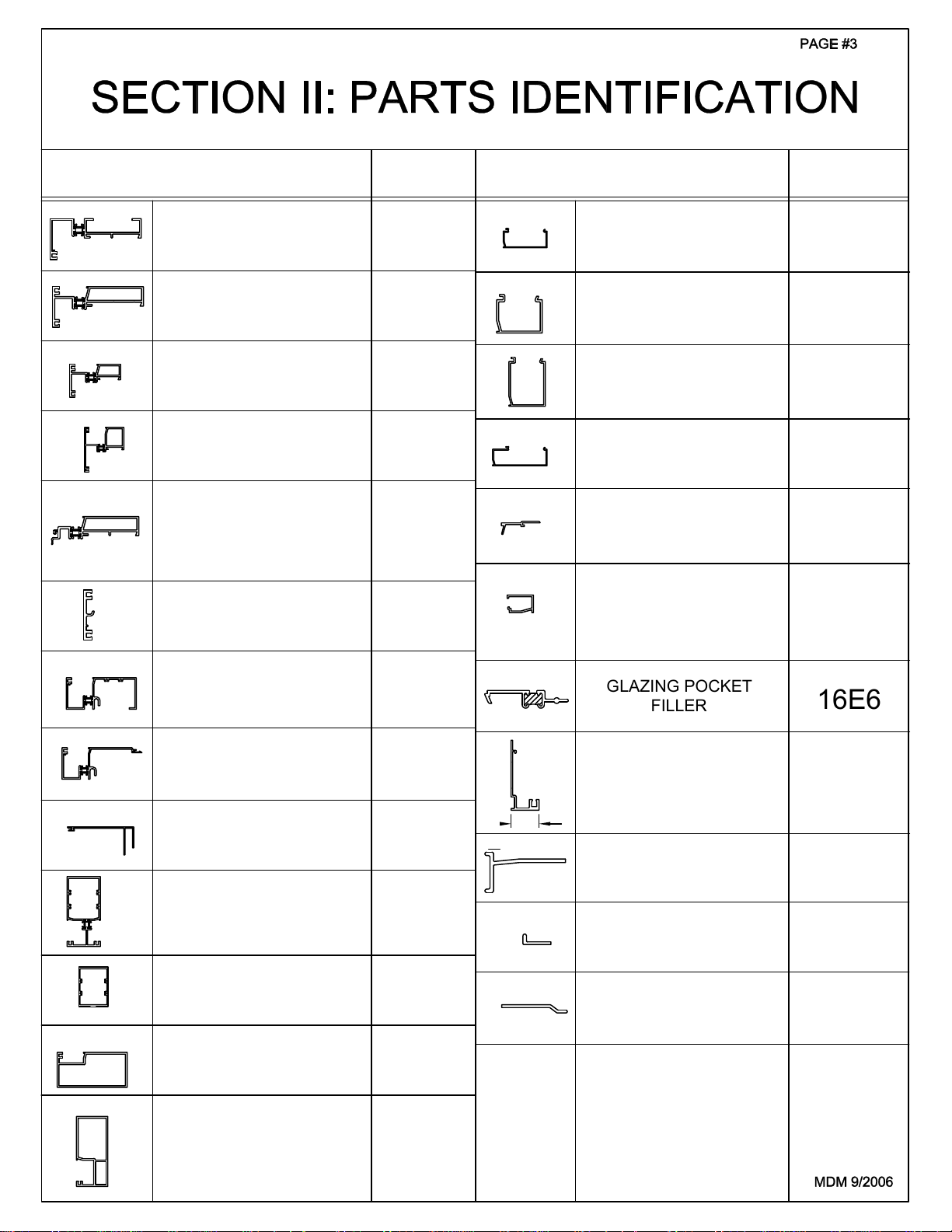
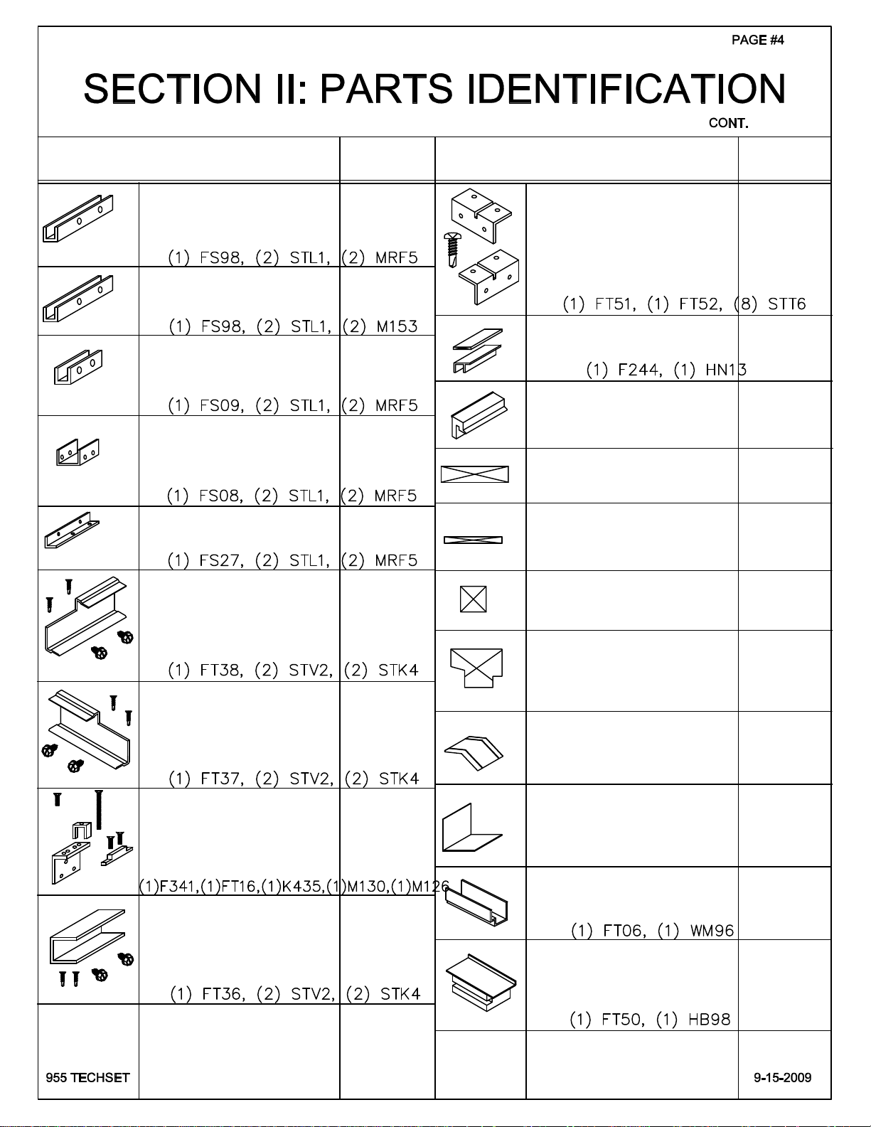
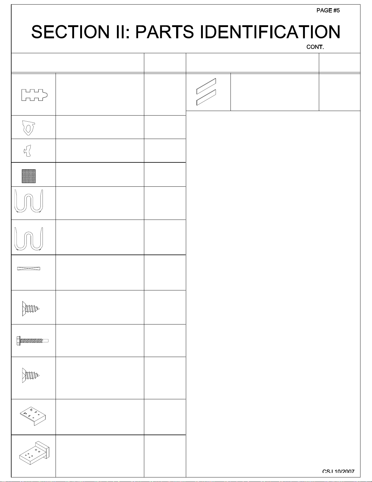
PARTS IDENTIFICATION
DRILL JIGS
DRILL JIG GUIDES
FABRICATION
ASSEMBLY
FRAME INSTALLATION
GLASS INSTALLATIONVII
DOOR FRAME INSTALLATION
3-5
6-7
8-11
12-21
22-26
27-30
31-39
40-43
Minimizing Condensation
NOTE: Please reference EFCO's "Understanding Condensation" brochure which can be obtained through your EFCO representative.
Condensation will form on any surface when unfavorab le con dition s (interior temperature an d relative humidity and exterior
temperature) are present. When the formation of excessive condensation is a concern, it is highly recommended that a design
professional is utilized to perform an analysis of the shop drawings to recommend the best installation methods. Please contac t
EFCO representative for information on EFCO's Thermal Analysis Servi c es .
Many current installation practices lead to an increase in the possibility of the formation of condensation. Though not all
inclusive, the list of examples below illustrates conditions under which condensation is likely to occur:
1. Bridging system thermal br eak with non-thermally br o ke n meta l flashing or lintel s th a t are exposed to the
exterior.
2. System exposure to cold air cavities.
3. Interior relative humidity levels not maintained at recommended levels, see EFCO's "Understanding
Condensation" brochure.
4. Inadequate separation between system and surrounding condition at perim eter.
5. Product combinations during the shop dra wing stage that result in bri d ging thermal brea ks of one or all pr oduct s
involved.
JWH 8/2011
Page 3

SECTION I - GENERAL NOTES AND GUIDELINES
SERIES 955 5" TECH SET
NOTE:
1.
THESE INSTALLATION INSTRUCTIONS ARE A SUP P L EM E NT TO
THE APPROVED SHOP DRAWINGS AND MUST BE USED IN
CONJUNCTION WITH THOSE DRAWINGS.
THESE INSTALLATION INSTRUCTIONS ARE ALSO WRITTEN TO
ACCOMMODATE THE STOCK LENGTH PURCHASE OF ALL
MATERIALS, PARTS, AND EXTRUSIONS.
HANDLING-S TORING-PRO TE CT IN G ALUMINUM- The foll owing
precautions are recommende d to assure ea rly accept an ce of your pro du ct s
and workmanship.
A. HANDLE CAR EFULLY- Store with adequate separation between com-
ponents so material will not become scratched or rubbed at points
of contact. Store off the ground. Protect against weather elements
and other construction trades in adjacent areas of the job site.
B. KEEP MATERIAL AWAY FROM WATER, MUD, AND SPRAY- Prevent
cement, plaster, and other materials from coming in contact with and
damaging the finish. Do no t allow moisture to be trapped between the
finished surface and the wrapping material.
C. PROTECT MATERIALS AFTER ER ECTI ON- Wr ap or erect visqueen
screens. Cement, plaster, terrazzo, and other alkaline materials are
very harmful to the finish and must be removed with water and mild
soap before setting occurs. Under no circumstances should these
materials be allowed to dry or permanent staining will occur.
GENERAL GUIDE LINES- The fol lowing practices are recommended for all
2.
installations.
A. Review the approved shop drawings to become thoroughly famillar
with the project.
B. All thermal strut horizontal and sill members require sealant applied
to the upper most cavity of the thermal strut race.
Refer to typical details of this system.
C. Install all framing mat erials plumb, level, and true.
Proper alignment and relationships to benchmarks and column center
lines, as established by the architectural drawings and the general
contractor, must be maintained.
BAH 4/2005
Page 4

PAGE #2
SECTION I - GENERAL NOTES AND GUIDELINES
CONT.
D. The sequence of erection should be coordinated with the project
superintendent so delays are prevented and the risk of material
damage is minimized. If preset anchors are required, coordinate
with the general contractor and supervise the locations.
E. Verify that all job site conditions and accompanying substrates
receiving the installation are in accordance with the contract documents. If deviations occur, notification must be given IN WRITING
to the general contractor and differences resolved before proceeding
further with the installation in the questionable area.
F. Coat all aluminum, to be placed directly in contact with masonry or
dissimilar materials, with a heavy coating of bituminous primer such
as zinc chromate.
G. Follow EFCO’s framing installation and glazing instructions.
H. Verify the contents of all material shipments upon arrival. Verify
quantities and correct finishes.
NOTIFY EFCO IMMEDIATELY OF ANY DESCREPANCIES OR
DAMAGES WHICH MAY HAVE OCCURRED.
I. Throughout these instructions the term SEALANT will appear. For the
purpose of these instructions, sealant is defined as follows:
SEALANT- A weather resistant, gunnable, liquid filler which when dry
provides a resilient, flexible air and water seal between similar and
dissimilar materials. Use Dow Corning 795 or equal. All sealant must
meet FEDERAL SPECIFICATION TT-S-00227E, TT-S-001543A, AND
TT-S-00230G.
NOTE:
NOTE:
All sealant must be compatible with all surfaces on which adhesion
is required, including other sealant surfaces. All frame surfaces
should be clean and dry. All perimeter substrate shall be cleaned
and properly treated to receive sealant.
DUE TO THE SCREW TENSIONS REQUIRED FOR CORRECT
INSTALLATION, IT WILL BE NECESSARY TO ’WAX’ THE FRAME
ASSEMBLY SCREWS TO PREVENT GALLING AND BREAKAGE.
TOOLS NEEDED:
1. Wedge hammer and/or gasket roller
2. Putty knife
3. Level and square
4. Cutting tool, hand pruner, etc.
5. #2 Phillips tipped screwdriver
6. Flat pry bar
7. Soft faced mallet
8. Tube wax
JDA 11/2000
Page 5
8687
8633
8554
DESCRIPTION
8686
8634
8633
8666
8687
8664
8667
8634
8688
FRAME HEAD
2 1/4" X 5" DEEP
USE 8685 STOP
INT. HORIZONTAL
2 1/4" X 5" DEEP
USE 8685 STOP
INT. HORIZONTAL
2 1/4" X 3 1/2" DEEP
USE #8665 GLASS STOP
INT. HORIZONTAL
4" X 3 1/2" DEEP
USE #8668 GLASS STOP
INT. HORIZONTAL
for BUTT GLAZE APPS.
2 1/4" X 5" DEEP
USE 8553 EXT. FACE
USE 8685 STOP
EXTERIOR FACE for
INT. HORIZONTAL 2G23
FRAME SILL/JAMB
2 1/4" X 5" DEEP
PART
NO.
IG58
IG67
IG72
IG73
2G23
8553
IG59
DESCRIPTION
REMOVABLE STOP
8685
USE w/ IG58, IG67 or 2G23
REMOVABLE STOP
8665
8685
8652
8651
1 INCH GLAZING
REMOVABLE STOP
1 INCH GLAZING
REMOVABLE STOP
1/4 INCH GLAZING
USE w/ IG58 or IG67
1/4" GLAZING
AT HORZ. AND VERT.
w/ SFZ5 SCREW
HOOK ON GLAZING
STOP for APPLIED
GLAZING at TRANSOM
GLAZING POCKET
1 INCH GLAZING
USE w/ IG72
USE w/ IG73
ADAPTOR
USE w/#8579
FILLER
PART
NO.
8685
8665
8668
8652
8651
8578
16E6
8687
8691
8690
8692
8693
8663
FRAME SILL for
STOOL TRIM
USE 8691 STOOL TRIM
SILL STOOL TRIM
4 3/4" DEEP
USE IG60 SILL
INT. VERT. MULL
2 3/8" X 5" DEEP
BUTT GLAZE
VERT. MULLION
2 3/8" X 5" DEEP
2 1/2" SIGHT LINE
TRANSOM BAR
FOR C.O.C. APLICATIONS
2 1/4" SIGHT LINE
DOOR JAMB
or TRANSOM BAR for
SURFACE CLOSER
IG60
8691
IG61
8663
8580
8581
1"
8695
8694
8635
SCREW APPLIED
STOP for TRANSOM
USE w/#8578
HEAD ANCHOR
3" LONG
SLIDE FIT w/ 1G58
HORZ. SILL ANCHOR
USE IG59 OR IG60 SILL
3" LONG
VERT. SILL ANCHOR
USE IG59 OR IG60 SILL
3" LONG
8579
FS97
FS99
FT01
Page 6
DESCRIPTION
PART
NO.
DESCRIPTION
PART
NO.
FT38
M130
F340
FT36
FS98
FS98
FS08
FS09
FS27
FT16
FT37
M126
K435
SHEAR BLOCK PKG.
for 1G67 & 2G23 HORIZ.
to VERTICALS
(HEAD & SILL RUN THRU)
SHEAR BLOCK PKG.
for 1G59 SILL at
VERT. INTER. THRU
SHEAR BLOCK PKG.
for 1G72 HORIZ.
to VERTICALS
(HEAD & SILL RUN THRU)
SHEAR BLOCK PKG.
for 1G73 HORIZ.
to VERTICALS
(HEAD & SILL RUN THRU)
SHEAR BLOCK PKG.
for HEAD & SILL
at VERT. THRU APP.
SHEAR BLOCK PAC KAGE
for S955 TRANSOM
BAR # 8580
CLEAR & BRONZ E
LEFT JAMB
SHEAR BLOCK PAC KAGE
for S955 TRANSOM
BAR # 8580
CLEAR & BRONZ E
RIGHT JAMB
SHEAR BLOCK PAC KAGE
for S955 TRANSOM
BAR # 8580
DORMA 88 COC
OFFSET PIVOTS
SHEAR BLOCK PAC KAGE
for S955 DOOR JAMB
# 8581 when used
as TRANSOM BAR
SURFACE CLOSER
K368
K319
K198
K197
K193
K451
K450
K453
K452
HN13
HB98
1918
1783
FT50
TRANSOM HEADER
CLIP PACKAGE
for 1G58
INCLUDES-
(1)FT51 & (1) FT52
& (8) STT6 SCREWS
SETTING CHAIR P KG.
for 1G73 HORIZ.
SETTING CHAIR P KG.
FOR 1G59 & 1G 60
GLASS SETTING B LOCK
AT TRANSOM BAR #8580
1/8" x 1" GLASS
SETTING BLOC K
USE w/ 1G67, 1G72 & 2G23
1/4" X 1/4" GLASS
SETTING BLOC K
USE w/ 8651 ADAPT OR
GLASS SETTING B LOCK
AT TRANSOM BAR #8581
DOOR JAMB AS TRANSOM BAR
w/ SURFACE CLOSER
WATER DEFLE C TOR
@ INT. HORIZONTAL
END CAP AT
HEAD & SILL
AT GLAZING POCKET
ALL 4 CORNERS
SPLICE JOINT
(BRAKE METAL)
AT GLAZING POCKET
HEAD & SILL
HORIZ. BRIDGE
ASSEMBLY for
BUTT GLAZE APPLICATIONS
K462
K196
HN35
HEP0
HN92
HEP2
H190
HWD1
FS96
K424
K461
Page 7
DESCRIPTION
PART
NO.
DESCRIPTION
PART
NO.
BUTT GLAZE
SPACER
1/2" x 1/4"
INTERIOR GLAZING
GASKET
EXTERIOR GLAZING
GASKET
WEEP BAFFLE
AT IG59 OR IG60 SILL
1/2" ANTIWALK BLOCK
USED AT 1/4" G L ASS
7/8" ANTIWALK BLOCK
USED AT 1" GLASS
WSA1
W105
WNB9
HCW3
HN50
HN53
FACE SPLICE
CAULK BACKER TAPE
(2) 1" X 3" PC. REQUIRED
PER SPLICE JOINT
WM96
1/8" X 1"
ANTIWALK BLOCK
AT VERTICAL
SHALLOW POCKET
1/4" G LAZING ADAPTOR
ATTACHMENT SCREW
USE w/ 8651
#8-15 x 3/8"
SCREW SPLINE
FRAME SCREW
#10-16 x 1 1/4"
TRANSOM JAMB
GLAZING ADAPTOR
ATTACHMENT SCREW
USE w/ 8579
#8-15 x 3/8"
DRILL JIG
FOR SHEAR BLOCK
& SCREW SPLINE
HN92
SFZ5
STV3
SFZ5
H262
DRILL JIG
FOR SHEAR BLOCK &
HORIZONTAL END PREP
WHEN USING 1G72 & 1G73
DJ06
Page 8
PAGE #6
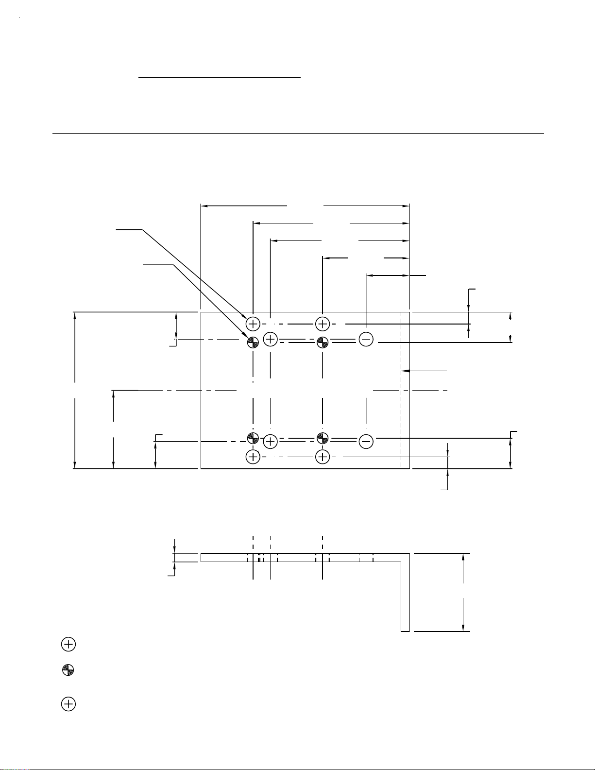
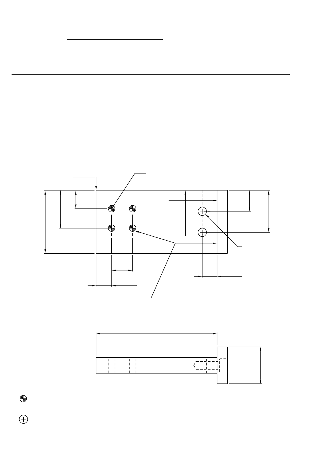
SECTION III - DRILL JIGS
DRILL JIG #H262 CAN ALSO BE PURCHASED
DRILL FIXTURE FOR INTERMEDIATE HORIZONTALS, VERTICALS AND JAMBS
The drill guide shown below is designed to be field prepared from 1" x 3"
aluminum angle. The drill guide is used by aligning off the back and
ends of the member being prepared.
3.000
#7 DRILL
.201 dia. (8)
#21 DRILL
.159" dia. (4)
LOCATE JIG EDGE AT
END OF HORIZONTAL
2.250
2.000
1.250
.625
.178
.375
2.375
1.188
.375
LOCATE JIG EDGE AT
END OF HORIZONTAL
.125
A
B
CENTER LINE OF MULLION
B
C
B
C
A
B
AA
.431
C
LOCATE JIG AT
BACK OF MULLION
.431
C
.178
1.000
= A = #7 (.201 dia.) drill for all screw spline
= B = #21 (.159 dia.) drill shear block to vertical mullion
REF. TOOLING DRAWING (001052 S.B. TO VERT. PREP)
= C = #7 (.201 dia.) intermediate horizontal to shear block
REF. TOOLING DRAWING (001051 HORIZ. END PREP)
KDE 12/2002955 Tech Set
Page 9
PAGE #7
SECTION III - DRILL JIGS
DRILL JIG #DJ06 FOR INTERMEDIATE HORIZONTALS #1G72 AND #1G73
The drill guide is used by aligning off the back and ends of the members being
prepared for shear blocks.
For the left side vertical members, drill from this side as shown below.
For the right side vertical members, turn the drill jig over and drill from the
opposite side.
TOP OF 1G72 or 1G73
HORIZONTAL
INTERMEDIATE
.438
.900
1.500
VERTICAL PREP FOR
HORIZONTAL INTERMEDIATE
SHEAR BLOCK ATTACHMENT
B
B
.500
.369
.159 DIA.
(#21 DRILL)
1G72
1G73
2.875
C
C
END PREP
HORIZONTAL
.500
1.000
.201 DIA.
(#7 DRILL)
.350
= B = #21 (.159 dia.) drill shear block to vertical mullion
= C = #7 (.201 dia.) intermediate horizontal to shear block
.875
JDA 9/2000
Page 10
PAGE #8
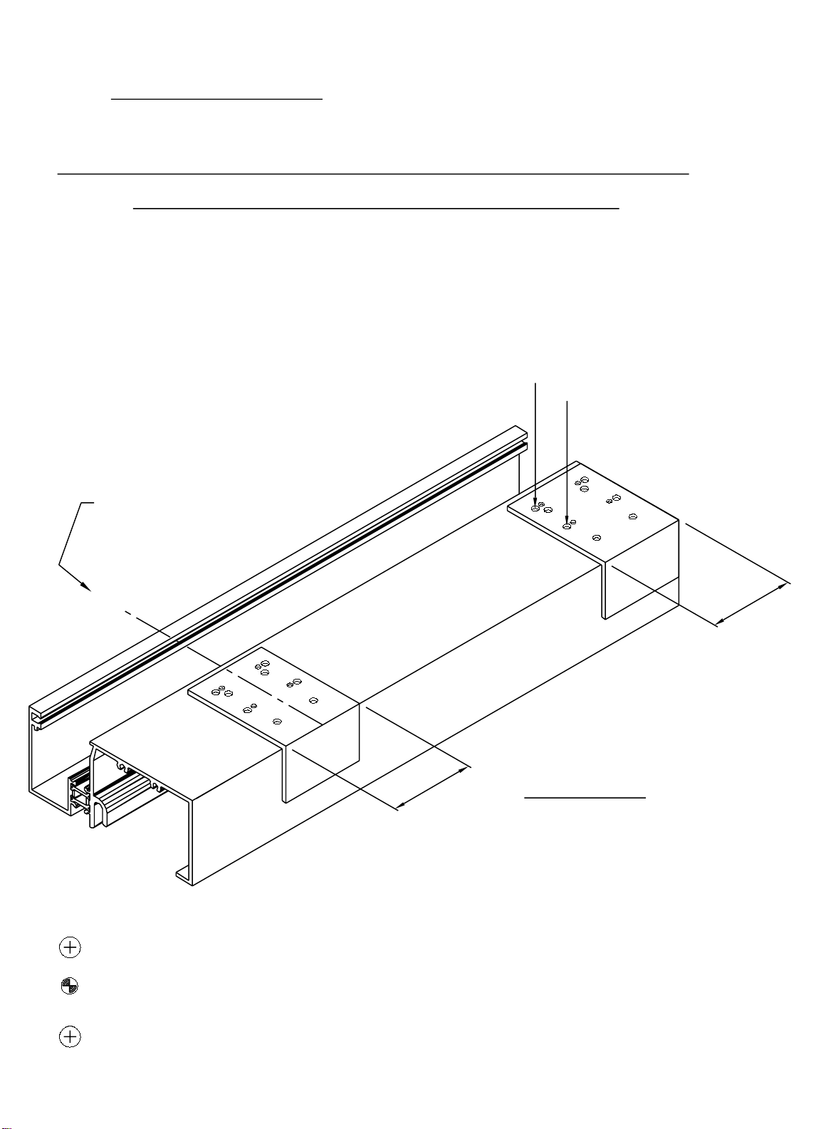
SECTION III - DRILL JIG GUIDE
CONT.
DRILL FIXTURE FOR INTERMEDIATE HORIZONTALS,
INTERMEDIATE VERTICALS AND JAMBS
The drill guide is used by aligning off the back and
ends or center lines of the member being prepared.
JAMB LOCATION
LOCATE DRILL JIG AT
END OF SILL AND HEAD.
APPLICATION
SCREW SPLINE
CENTER LINE OF
VERTICAL MULLION
C
L
2 3/8"
2 3/8"
SILL SHOWN,
HEAD SIMILAR
Detail #1
REFER TO PAGE #6 FOR SPECIFIC HOLE LOCATIONS.
= A = #7 (.201 dia.) drill for all screw spline
= B = #21 (.159 dia.) drill shear block to vertical mullion
REF. TOOLING DRAWING (001052 S.B. TO VERT. PREP)
= C = #7 (.201 dia.) intermediate horizontal to shear block
REF. TOOLING DRAWING (001051 HORIZ. END PREP)
JDA 11/2000
Page 11
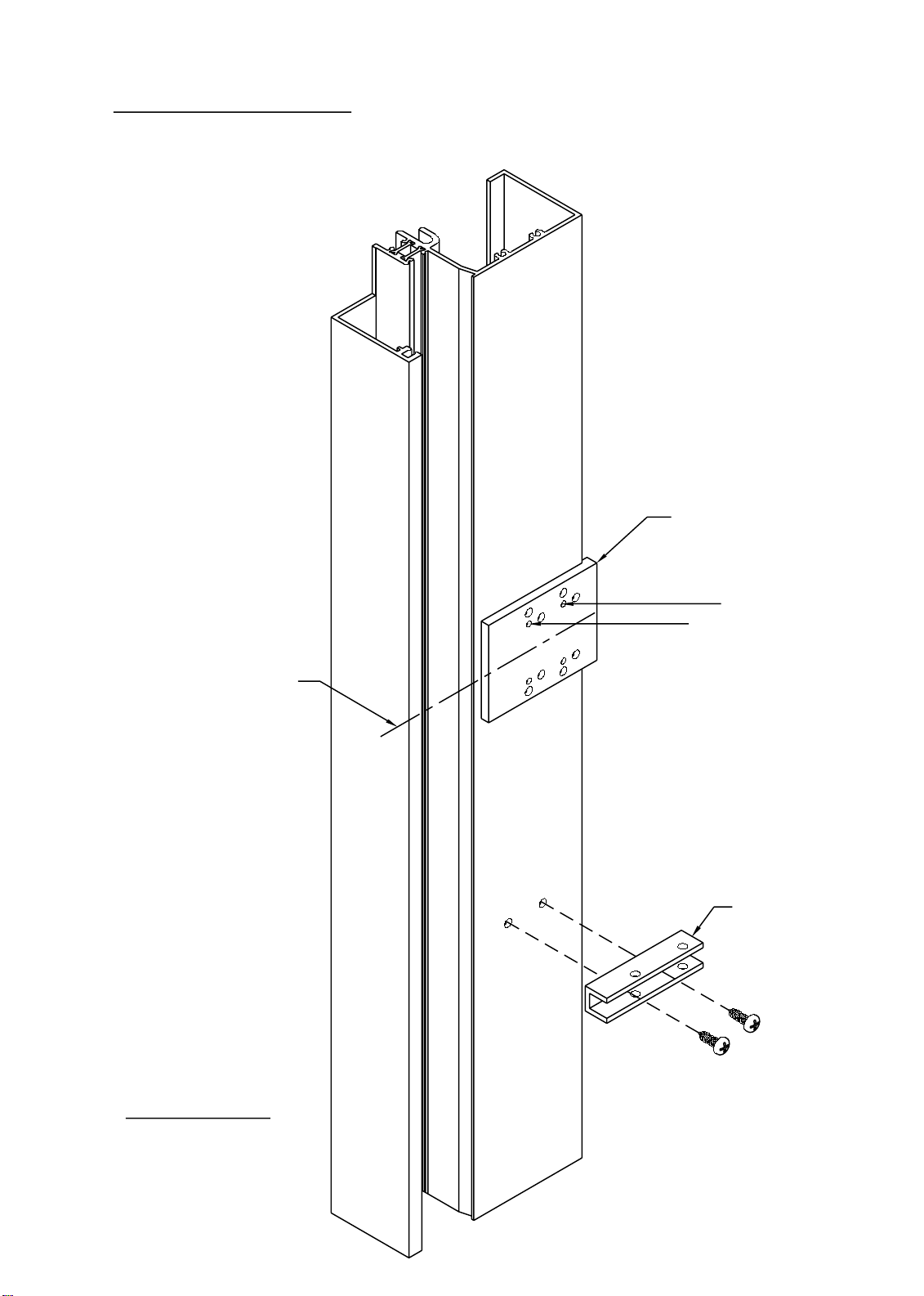
SECTION III - DRILL JIG GUIDE
LEFT JAMB SHOWN,
RIGHT JAMB AND
INTERMEDIATE VERTICALS
ARE PREPPED SIMILAR.
PAGE #9
CONT.
CENTER LINE OF
HORIZONTAL
INTERMEDIATE
REFER TO PAGE #6
FOR SPECIFIC HOLE
LOCATIONS ON THE
DRILL JIG.
1G59
H262
DRILL JIG
SHEAR BLOCK
APPLICATION
C
L
K368 SHEAR BLOCK
SHOWN
Detail #2
JDA 9/2000
Page 12
PAGE #10
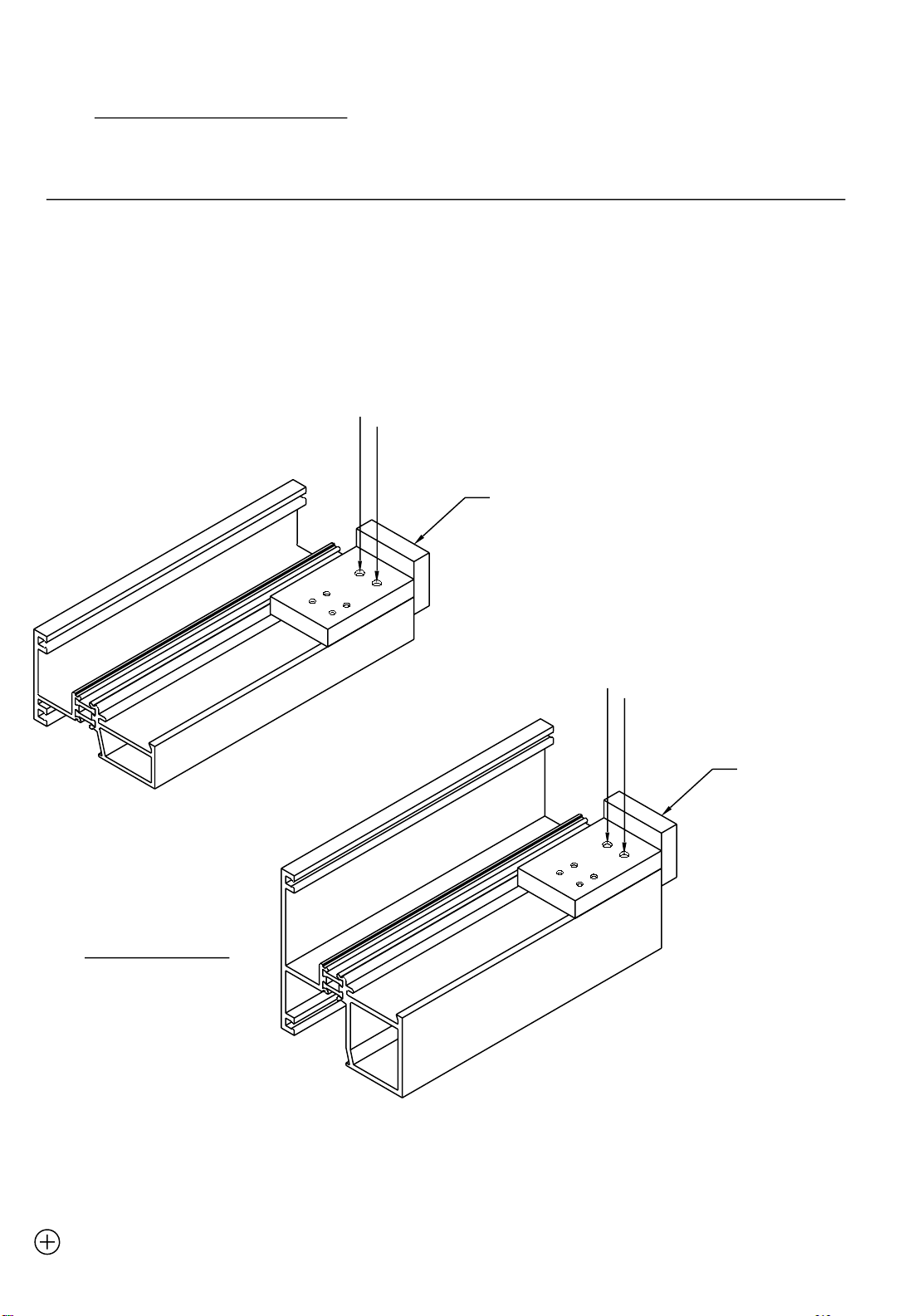
SECTION III - DRILL JIG GUIDE
CONT.
DRILL JIG #DJ06 FOR INTERMEDIATE HORIZONTALS #1G72 AND #1G73
INTERMEDIATE HORIZONTAL TO SHEAR BLOCK ATTACHMENT
This drill guide is used by aligning off the ends of the
horizontal intermediate member being prepared.
See Detail #3 below.
C
C
DJ06
DRILL JIG
Detail #3
1G72
1G73
C
C
DJ06
DRILL JIG
= C = #7 (.201 dia.) intermediate horizontal to shear block
JDA 9/2000
Page 13
SECTION III - DRILL JIG GUIDE
LEFT JAMB SHOWN,
RIGHT JAMB AND
INTERMEDIATE VERTICALS
ARE PREPPED SIMILAR.
PAGE #11
CONT.
TOP OF
HORIZONTAL
INTERMEDIATE
REFER TO PAGE #7
FOR SPECIFIC HOLE
LOCATIONS ON THE
DRILL JIG.
1G59
DJ06
DRILL JIG
FOR 1G72 (B)
FOR 1G73 (B)
K198 SHEAR BLOCK
SHOWN,
K197 IS SIMILAR.
Detail #4
= B = #21 (.159 dia.) drill shear block to vertical mullion.
JDA 9/2000
Page 14
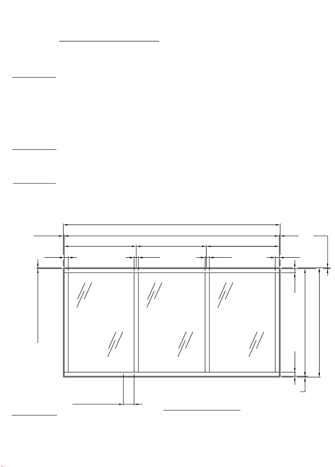
SECTION IV - FABRICATION
HEAD AND SILL FABRICATION AND PREPARATION
STEP #1
The series 955 Tech Set system is designed to be fabricated with the head
and sill running through. The jambs and vertical mullions will meet at the
top of the sill and at the snap location of the removable stop at the head.
Cut the head and sill members to the rough opening measurement minus
(-) the vertical caulk joints. This dimension could be 1/4" through 3/4"
depending upon the condition. See Elevation #1 below.
STEP #2
Establish and mark the mullion center lines and jamb locations on the head
and sill. Mullion widths are 2 3/8" as shown below.
STEP #3
PAGE #12
Position the drill guides over the mullion and jamb locations and drill as
required. See pages #6 thru #11 for the drill jigs and drill jig guides required
for assembling this system.
ROUGH OPENING WIDTH
CAULK
JOINT
2 1/4"
3/4" TOP CAULK JOINT
MULL. CENTER
FRAME WIDTH
MULL. CENTER
2 3/8"
MULL. CENTER
2 3/8"
CAULK
JOINT
2 1/4"
2 1/4"
FRAME HEIGHT
2 1/4"
ROUGH OPENING HEIGHT
WEEP 6"
FROM MULL
TYPICAL
1/2" BTM. CAULK JOINT
ELEVATION #1
STEP #4
Drill the sill member for two 1/4" weep holes per daylight opening, at 6" from each mullion.
See Elevation #1 above and Detail #5 & #6 on page #13.
JDA 9/2000
Page 15

1/4" dia.
WEEP
C
L
APPLY A CONTINU OUS
BEAD OF SEALANT A ND
TOOL INTO THE TH ERMAL
STRUT RACE.
DO NOT BLOCK
1/4"
THE WEEP HOL E
WITH SEALANT
APPLY A SMALL AMOUNT OF
SILICONE SEALANT TO BOTH SIDES
OF THE WEEP HOLE LOCA TION.
USE ONE BLOCK PER WEEP HOLE,
AS REQUIRED.
CENTER LINE
3/4"
OF WEEP HOLE
4"
2"
Detail #5
FS96
1"
#HCW3
CUT IN HALF
Detail #6
1/2"
GAP
Detail #7
SEAL ALL
INTERIOR
CORNERS WIT H
SEALANT
K424
Detail #8
FS96
BAH 4/2005
Page 16

PAGE #14
SECTION IV - FABRICATION
CONT.
INTERMEDIATE HORIZONTAL FABRICATION AND PREPARATION
STEP #7
Cut the intermediate horizontals to D.L.O. width. Cut the glass stops for the
intermediate horizontals and head member to D.L.O. minus (-) 1/32" for
ease of installation.
STEP #8
Prep the ends of the intermediate horizontals for the horizontal to shear block prep.
See detail #9 below. See page #6 for the drill guide required to correctly
identify the holes required for the shear block attachment.
2G23
1G67
K368
SHEAR BLOCK
PKG.
Detail #9
1.875
.500
CB
A
A
B C
.375
C
A
B
DRILL GUIDE
A
BC
.201" DIA. THRU (1) WALL
(2 PLACES)
955 Tech Set
KDE 01/2003
Page 17

PAGE #15
SECTION IV - FABRICATION
(CONT.)
INTERMEDIATE HORIZONTAL FACE
STEP #9
Cut horizontal face member (#8553) to span 3 lites (or a maximum of 15’-0"). Allow
1/4" at splice joints for expansion. Splice ONLY at center lines of vertical mullions.
See Detail #10 below.
1G59
NOTE:
D.L.O. 2 3/8"
INTERIOR
8663
HORIZONTAL FACE LENGTH (15 ft. max.)
D.L.O.
K461 BRIDGE
REQUIRED
2 3/8"
8663
D.L.O.
Detail #10
Due to the expansion characteristics of the aluminum face member
and also to maintain the 1/4" splice joint, 15 feet is the recommended
cut length for the face member. Use #WM96 bond breaker tape,
{
3" long and trimmed to fit, for the face splice caulk backer.
1/4"
D.L.O.2 3/8"
8663
1/4"
BOND BREAKER TAPE APPLIED
TO INSIDE OF FACE MEMBER
CENTERED ON GAP
GAP DETAIL EXAGGERATED
STEP #10
FOR CLARITY
Weep baffles are cut from (1) HCW3, halved and then quartered. This provides
8) weep baffles per HCW3 to be used at the horizontal face. See Detail #11 below.
3/8"
3/4"
4"
2"
1"
1/2"
Detail #11
HCW3
JDA 11/2000
Page 18
PAGE #16
SECTION IV - FABRICATION
(CONT.)
INTERMEDIATE HORIZONTAL FACE
STEP #11
Drill 1/4" diameter weep holes in the horizontal face member at 48" on center or
2 per D.L.O. at quarter points. Install weep baffles over the holes with silicone.
Do not plug the weep holes with silicone.
See Detail #12 below.
1/4" DIA.
WEEP
HOLES
15/16"
C
L
8553 FACE
WNB9
WNB9
APPLY BAFFLES WITH A SMALL
AMOUNT OF SILICONE TYPE SEALANT.
DAYLIGHT OPENING
48" O.C.
Detail #12
STEP #12
Install the exterior glazing gasket into the face member at this time, (WNB9).
Be sure to add 2% to the cut length to prevent gaps at gasket intersections.
See Detail #12 above.
JDA 9/2000
Page 19

PAGE #17
SECTION IV - FABRICATION
(CONT.)
INTERMEDIATE HORIZONTAL FACE
JAMB AND VERTICAL MULLION FABRICATION AND PREPARATION
STEP #13
If the project is being built as head and sill thru, the vertical members will be cut to
D.L.O. plus (+) 1 3/16".
STEP #14
The vertical members must also be coped to fit into the head.
See details #13 and #14 below.
Detail #13
Detail #14
1G59 JAMB
1G61
VERTICAL MULLION
1.187
1G58 HEAD
1.187
TO HEAD
STEP #15
If there are NO horizontal members being used, the vertical members are
now ready to be screw spline attached to the head and sill members.
Refer to page 22 for assembly procedures.
JDA 9/2000
Page 20

PAGE #18
SECTION IV - FABRICATION
CONT.
STEP #16
If horizontal intermediates are being incorporated, the verticals must be
prepped for the horizontal shear block attachment.
See detail #15 below to determine the horizontal location.
Refer to pages #6 through #11 for the drill jigs and the drill jig guides to correctly
identify the required holes to drill for the particular horizontal / shear block
being used.
THIS PREP FOR
1G67 & 2G23
HORIZONTALS
C
L
1.187
1.187
TO HEAD
.431
2.250
.159 DIA. (#21) DRILL
THRU (1) WALL
(2 PLACES)
REF.
Detail #15
955 Tech Set
2.125
1.125
H262
DRILL JIG
KDE 12/2002
Page 21

PAGE #19
SECTION IV - FABRICATION
HORIZONTAL INTERMEDIATE
SHEAR BLOCK FABRICATION
STEP #17
The intermediate horizontal shear blocks are to be prepped from #EX43.
One (1) #EX43 is required at each end of the intermediate horizontal.
See detail #16 below for preparation.
2.750
1.000
#7 DRILL (.201) THRU
CLEAR HOLE FOR
#10 SCREW
#STL1 - TYP.
{K368 FABRICATED PACKAGE}
.968
C
L
.350
CONT.
EX43
# 25 DRILL (.1495)
Detail #16
1.375
.360
.350
THRU 2 WALLS
PILOT HOLE FOR
#10 SCREW
#MRF5 - TYP.
SILL ANCHOR FABRICATION
{FS99 & FT01 ARE
STEP #18
There are two (2) types of sill anchors used for the 955 system. Cut and
fabricate #8694 or #8635 as shown in detail #17 below.
3.000"
1.500"
.313" DIA. (5/16")
DRILL THRU
FABRICATED PARTS}
(5/16" x 13/16" SLOT)
1.500"
3.000"
FS99
.875"
8694
FT01
8635
Detail #17
.500"
1.000"
JDA 9/2000
Page 22

PAGE #20
SECTION IV - FABRICATION
HEAD ANCHOR FABRICATION
STEP #19
Cut and fabricate the head anchors from #8695 as shown in detail #18
below.
FS97
.500"
{FS97 - FABRICATED PART}
CONT.
1.000"
5/16" x 13/16"
SLOT
1.500"
Detail #18
1/2 SIZE
SETTING BLOCK
FABRICATION
3.000"
K196 FOR 1G73
FABRICATED PACKAGE IS AVAILABLE.
STEP #20
Cut and fabricate the setting blocks from #1918 extrusions. Two (2) setting
blocks are required per daylight opening. See detail #19 below for fabrication.
STEP #21
Install one (1) #HN13 to the top of #1918 for use with 1G73 intermediate horizontal.
Detail #19
HN13
APPLY A SMALL
AMOUNT OF
SILICONE TO THE
SETTING CHAIR TO
SET THE BLOCK IN.
1/2 SIZE
4.000"
BAB 3/2001
Page 23

PAGE #21
SECTION IV - FABRICATION
CONT.
1/4" GLAZING ADAPTOR FABRICATION AND PREPARATION
STEP #22
Cut the #8651 glazing adaptor to daylight opening minus 1/16" for verticals and
horizontals. See detail #20 below.
STEP #23
Notch the #8651 horizontal glazing adaptors to clear the vertical adaptors as shown
in detail #21 below.
Prep the glazing adaptors for the attachment screws as shown below.
Butt the horizontal adaptor to the vertical and fasten with SFZ5 screws as shown.
DAYLIGHT OPENING
HORIZONTAL & VERTICAL
.128" DIA. (#30)
DRILL THRU
& CNTR SINK
for SFZ5
2" FROM END 12" O.C. 2" FROM END12" O.C.
VERTICAL ADAPTOR
RUNS THROUGH
NOTCH HORIZONTAL
ADAPTOR AROUND
VERTICAL ADAPTOR
Detail #20
#SFZ5
.125
.687
8651
Detail #21
SEE TOOLING DRAWING
001096 FOR END PREP
JDA 9/2000
Page 24

1G67
Apply a continuous
bead of silicone and
tool into the thermal
strut race .
1G67 SHOWN,
SEALANT APPLICATION
TYPICAL AT ALL
HORIZONTALS.
Apply silicone sealant
to the ends of the
intermediate horizontals
Detail #22
Apply a continuous
bead of silicone and
tool into the thermal
strut race .
2G23
Apply silicone sealant
to the ends of the
intermediate horizontals
Detail #23
BAH 4/2005
Page 25

PAGE #23
SECTION V - ASSEMBLY
CONT.
FRAME PREASSEMBLY
with standard verticals and horizontals.
STEP #26
Attach the intermediate horizontal shear blocks to the vertical mullions and
jambs. See detail #24 below.
STEP #27
Attach the intermediate horizontals to the vertical mullions and jambs.
See detail #24 below.
JAMB
1G59
#K368 SHEAR BLOCK
(1) PER END OF
HORIZONTAL INTERMEDIATE
VERTICAL
MULLION
1G61
STANDARD
HORIZONTAL
INTERMEDIATE
1G67
Detail #24
JDA 9/2000
Page 26

PAGE #24
SECTION V - ASSEMBLY
CONT.
STEP #28
Butter the top ends of the jambs and vertical mullions. Then attach the head
to the verticals with #STV3 screws. It will be necessary to coat the screws with
wax before installation to prevent stripping. See details #25 and #26 below.
STEP #29
Butter the bottom ends of the jambs and vertical mullions. Then attach the sill
to the verticals with #STV3 screws. It will be necessary to coat the screws with
wax before installation to prevent stripping. See details #27 and #26 below.
Detail #25
Detail #26
Detail #27
STEP #30
Depending on the height of the assembled frame, it may be easier to install the exterior
glazing gasket (WMB9) with the frame laying flat. This is at the discretion of the installer.
Be sure to add approximately 2% of the cut length to prevent gaps at the gasket
intersections.
JDA 8/2000
Page 27

PAGE #25
SECTION V - ASSEMBLY
CONT.
FRAME PREASSEMBLY
with butt glazed vertical intermediates and roll on
face horizontals.
STEP #31
Attach the intermediate horizontal shear blocks to the vertical mullions and
jambs. See detail #28 below.
STEP #32
Attach the intermediate horizontals to the vertical mullions and jambs. See
detail #28 below.
JAMB
1G59
Detail #28
#K368 (1)
PER SIDE
ROLL ON FACE
HORIZONTAL
2G23
ROLL ON FACE
HORIZONTAL
2G23
BUTT GLAZE
MULLION
8663
JDA 9/2000
Page 28

PAGE #26
SECTION V - ASSEMBLY
CONT.
STEP #33
Butter the top ends of the jambs and vertical butt glaze mullions. Then attach the head
to the verticals with #STV3 screws. It will be necessary to coat the screws with
wax before installation to prevent stripping. See details #29 and #30 below.
STEP #34
Butter the bottom ends of the jambs and vertical butt glaze mullions. Then attach the
sill to the verticals with #STV3 screws. It will be necessary to coat the screws with
wax before installation to prevent stripping. See details #31 and #30 below.
NOTE THE GAP BETWEEN
THE HORIZONTALS. THIS
WILL BE FILLED WITH
THE K461 BRIDGE ASSEMBLY.
REFERENCE SECTION VII
Detail #29
1G59 STD. JAMB
FRAME SILL
1G59 or 1G60
2G23
VERTICAL
8663 BUTT GLAZE
2G23
VERTICAL
8663 BUTT GLAZE
2G23
1G59 STD. JAMB
1G58 STD. HEAD
Detail #30
Detail #31
STEP #35
Depending on the height of the assembled frame, it may be easier to install the exterior
glazing gasket (WMB9) with the frame laying flat. This is at the discretion of the installer.
Be sure to add approximately 2% of the cut length to prevent gaps at the gasket
intersections.
JDA 9/2000
Page 29

PAGE #27
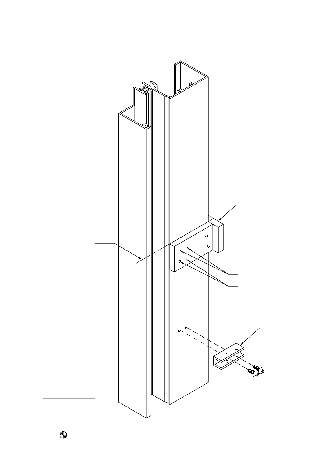
SECTION VI - FRAME INSTALLATION
CONT.
HORIZONTAL SILL ANCHOR INSTALLATION
STEP #36
At both ends of the rough opening, mark where the face of the frame is
intended to be located. Snap a chalk line from both marks. From this
dimension, snap another line 3 1/8" back toward the interior of the opening.
This will be the center line of the sill anchor prep. See detail #32 below.
STEP #37
Mark the center lines of the frame mullions on the rough opening. Measure
over from the mullion and jamb centers 6" and 16" O.C. and mark the interior line. This will be the center line of the anchor fastener. Drill the holes
for 1/4" diameter fasteners. Shim and install the anchor. See detail #33 below.
R.O. HEIGHT
6" 6"6"
ROUGH OPENING WIDTH
EXTERIOR FACE
OF OPENING
Detail #32
FACE OF
FRAME
CENTER LINE
OF ANCHOR
{FS99}
1/2" SHIM
3 1/8"
MULLION
CENTER
CENTER LINE
OF SILL ANCHOR
TYPICAL BOTH SIDES
OF VERT. MULLION
AND FROM JAMBS
6"6"
MULLION
CENTER
Detail #33
JDA 9/2000
Page 30

PAGE #28
SECTION VI - FRAME INSTALLATION
CONT.
HEAD ANCHOR AND VERTICAL SILL ANCHOR INSTALLATION
{FS97 & FT01 - FABRICATED PARTS}
STEP #38
Mark the center lines of the frame mullions on the rough opening. Measure
over from the mullion and jamb centers 6" and 16" O.C.
The vertical sill anchors, FT01, will be installed prior to
setting the assembled frame, as shown in Detail #35 below.
The silde in head anchors, FS97, are installed into the assembled frame head,
2 per D.L.O. and maintain the anchor dimensions as above.
Refer to Detail #34 below and page #29.
2 1/2"
MIN.
Detail #34
IG58
FS97
3"
L
C
ANCHOR
LOCATIONS
16" O.C.
5" MIN.
3/4"
16" O.C.
6"
6"6"6"
6"
MULLION
CENTER
2 1/2"
MIN.
INTERIOR FACE
OF OPENING
1G59
1G60
3/4"
MULLION
CENTER
Detail #35
FT01
3"
4" MIN.
JDA 9/2000
Page 31

PAGE #29
SECTION VI - FRAME INSTALLATION
CONT.
FRAME INSTALLATION INTO THE OPENING
{FS97, FT01 & FS99 - FABRICATED PARTS}
STEP #39
Slide the FS97 head anchor into the head as shown in Detail #36 below.
SLIDE THE HEAD
ANCHOR INTO THE
HEAD MEMBER 6"
OFF EACH MULLION
AND 16" ON CENTER.
Detail #36
FS97
6" FROM
VERTICALS
6" FROM
VERTICALS
16" O.C.
MAX.
INTERIOR
Detail #37
Detail #38
STEP #40
The 955 system is designed to rotate into the opening from the interior of
the building. Align the sill over the sill anchors and rotate the frame
into the opening and fasten as required. See details #37 and #38 above.
FS99
FT01
JDA 9/2000
Page 32

PAGE #30
SECTION VI - FRAME INSTALLATION
CONT.
BACKER ROD / EXTERIOR SEAL AND EXTERIOR GASKET
STEP #41
Install a continuous row of backer rod at the exterior side of the frame
and seal with silicone sealant. See the various details below.
STEP #42
If the exterior glazing preset gasket (WNB9) has not been installed at this time,
do so now. Be sure to add 2% of the cut length to the gasket to prevent gaps
at the gasket ends due to gasket shrinkage.
CUT LENGTH FORMULA
FOR WNB9 = D.L.O. + 2%
JAMB
WNB9
WNB9
HEAD ANCHOR
(FS97)
HEAD
SILL
HORIZ. SILL
ANCHOR
(FS99)
WNB9
3/4"
1/2"
WNB9
SILL
3/4"
VERT. SILL
ANCHOR
(FT01)
1/2"
Detail #39
JDA 9/2000
Page 33

PO
1
IN
HN07
SETTING BLO CK
SEAL HN92
IN PLACE
/4
T
1
/4
PO
IN
T
HN3
PO
1
IN
/4
T
1
/4
PO
IN
T
Page 34

PAGE #32
SECTION VII - GLASS INSTALLATION
CONT.
STEP #46
HWD1 WATER DEFLECTOR
AT VERTICAL INTERMEDIATE,
LEFT JAMB, AND RIGHT JAMB
1G61
Remove the paper backing and
position the water deflector
as shown in this figure.
It will be necessary to set the water deflector
in a small amount of sealant, to ensure
that it stays in place when setting the lower
glass unit.
1G67 STD.
Detail # 44
This end extends into
the vertical glazing pocket
and over the lower glass
unit’s corner.
1G72, 1G73,
& 2G23 OPT.
TYP. VERTICAL
HWD1
WATER DEFLECTOR
SET IN SEALANT
TYP. HORIZONTAL
Detail # 45
GLASS UNIT BELOW
955 TECH SET
DPS 12/2001
Page 35

PAGE #33
SECTION VII - GLASS INSTALLATION
USING BUTT GLAZED MULLIONS
CONT.
STEP #47
The horizontal bridge is intended to prevent any water in the glazing
pocket from running down the butt glazed vertical intermediate at the
horizontal connection. Correct sealing is important in this step.
Apply a bead of sealant around the opening of the left and right horizontals and
across the vertical butt glaze mullion. This is to set the bridge assembly into.
See detail #47 below.
FT51
K461
Detail #46
BEAD OF
SEALANT
HORIZONTAL BRIDGE
HB98
BUTT GLAZE
MULLION
8663
HORIZONTAL
2G23
Detail #47
JDA 9/2000
Page 36

PAGE #34
SECTION VII - GLASS INSTALLATION
USING BUTT GLAZED MULLIONS
CONT.
BUTT GLAZE
MULLION
8663
HORIZONTAL
2G23
K461
STEP #48
AFTER THE BRIDGE IS SET IN PLACE,
SEAL AROUND BRIDGE PERIMETER
WITH A NONHARDENING
BUTYL TYPE SEALANT.
Detail #48
JDA 9/2000
Page 37

PAGE #35
SECTION VII - GLASS INSTALLATION
USING BUTT GLAZED MULLIONS
STEP #49
Follow the glass setting procedure as shown in
Detail #50 below and Detail #51 on page #36.
8663 1G688663
BUTT GLAZED
MULLION
INSTALL THIS UNIT
BUTT GLAZED
MULLION
- LAST -
CONT.
JAMB
INSTALL THIS UNIT
- 2nd TO LAST -
EXTERIOR GLAZING GASKET
WNB9 INSTALLED
STEP #50
Position the glass units as shown in Detail #50 below maintain the
appropriate glass bite per mullion.
Detail #49
8663 8663
1/2"
GAP
15/16"
GLASS
BITE
1/2"
GAP
15/16"
GLASS
BITE
1G68
1/2"
GLASS
BITE
Detail #50
JDA 9/2000
Page 38

PAGE #36
SECTION VII - GLASS INSTALLATION
USING BUTT GLAZED MULLIONS
CONT.
STEP #51
Install the butt glazing spacer (WSA1) between the butt glaze mullion and the
glass unit. This gap should be small enough to provide tension on the spacer
to hold it in place. The space will bottom out against the locator on the mullion.
K368
WSA1
Detail #51
WSA1
K368
8663
1/2"
GAP
NOTE:
Any type of temporary glazing retainer will have to be field fabricated and
installed by the contractor.
STEP #52
Be sure the glass units are set correctly and the butt glaze spacer is bottomed
out, before proceeding with the application of the structural silicone.
Fill the cavity created by the spacer with structural silicone, tying the glass unit,
the spacer, and the butt glaze mullion together.
A clean professional application of the structural silicone is required here.
This structural silicone joint will require an overnight cure.
8663
MULLION
WSA1
STRUCTURAL
SILICONE
Detail #52
GLASS
UNIT
JDA 9/2000
Page 39

PAGE #37
SECTION VII - GLASS INSTALLATION
USING BUTT GLAZED MULLIONS
CONT.
STEP #53
After the interior structural joint has cured overnight the exterior joint seal
can then be applied. Use backer rod to fill the cavity to 2/3 full leaving
enough void to seal the exterior glass panes together. See Detail # 53 below.
A clean professional application of the structural silicone is required here.
8663
MULLION
WSA1
STRUCTURAL
SILICONE
Detail #53
GLASS
UNIT
JDA 9/2000
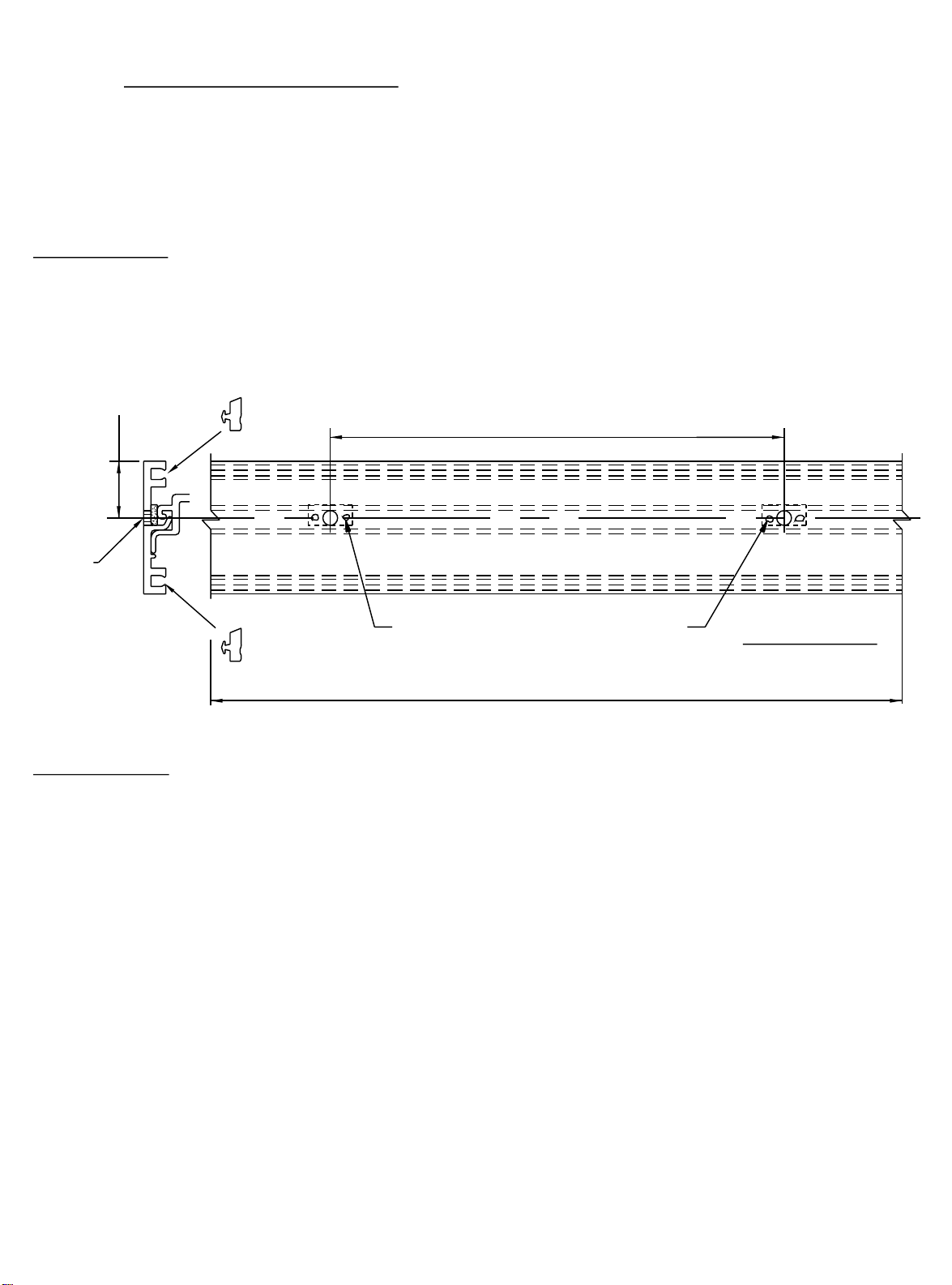
Page 40

PAGE #38
SECTION VII - GLASS INSTALLATION
CONT.
HORIZONTAL GLASS SIZE FORMULA (D.L.O. + 1.000")
VERTICAL GLASS SIZE FORMULA (D.L.O. + 1" or D.L.O. + 7/8")
STEP #54
The glass size formulas for the 955 system are based on D.L.O. plus 1", horizontally
and D.L.O. plus 1" or 7/8", vertically. This applies to both 1" and 1/4" glazed systems.
If only a head and sill are used, use D.L.O. + 1". If any intermediate horizontals
are used, the formula should be D.L.O. + 7/8". See detail #54 below.
TYP.
1/2"
8685 GLZ. STOP
Detail #54
D.L.O.
GLASS SIZE = D.L.O. + 1"
TYP.
1/2"
GLASS INSTALLATION
TYP.
7/16"
D.L.O.
GLASS SIZE =
TYP.
7/16"
D.L.O.
D.L.O. + 7/8" D.L.O. + 7/8"
GLASS SIZE =
TYP.
7/16"
8685 GLZ. STOP
8685 GLZ. STOP
STEP #55
From the interior of the system, install the glass into the deep glass pocket.
Swing the opposing end of the glass around to align with the glass pocket.
Shift the glass into the shallow glass pocket until there is equal glass bite
at both sides of the glass. Rest the glass on the setting blocks.
See Detail #55 below.
1
Detail #55
2
8651
3
955 TECHSET
DPS 4/2004
Page 41

PAGE #3
9
SECTION VII - GLASS INSTALLATION
CONT.
ANTIWALK BLOCK INSTALLATION
STEP #56
Choose the appropriate antiwalk block for the required glass type. Use
block #HN50 at 1/4" glass and #HN53 at 1" glass. Compress the anti-
walk and insert into the deep pocket at midpoint. See the details below.
#HN50 OR
#HN53
#8685 OR
#8652 STOP
Detail #56
ANTIWALK
BLOCK
REQUIRED AT
DEEP POCKET
ONLY
ANTIWALK
INTERIOR GASKET INSTALLATION
LOCATE AT THE
MIDPOINT OF LITE
Detail #57
BLOCK
Detail #58
STEP #57
Install the horizontal removable glass stops to the openings at the head and
intermediate horizontals. See detail #57 above.
STEP #58
Cut the drive-in wedge gasket (W105) to the height and width D.L.O (+) 2%.
Install the vertical gasket first, then follow with the horizontal gasket.
Insert the ends of the gasket first, then set the middle and proceed to set
the middle of the loops until the gasket is installed.
JDA 9/2000
Page 42

PAGE #40
SECTION VIII - DOOR FRAME INSTALLATION
NOTE: If an entrance frame is required, it must be installed first.
See the parts description pages for the appropriate door jamb
and transom bar for the system being used.
STEP 1)
STEP 2)
STEP 3)
STEP 4)
Correctly locate the entrance frame in the opening.
Apply a bead of sealant around the interior portion of the jamb
to set the member into, and tie the side lite sealant or condition
sealant into the bead of sealant to be applied under the threshold.
The concept is to have a continuous bead of sealant at the interior
and connected from the sill flashing condition through the door
jamb and continuing under the threshold to the opposite door jamb.
Set assembled door frame in opening, plumb, and level.
Anchor the door frame as indicated below in Detail #59 and also in
Detail #60, #62, and #64 through Detail #66 on page # 41.
SIDE LITE SILL MEMBER
NOTE:
The door jamb runs to the
floor and is cut longer
than any other vertical
member.
K-124/K-125 Threshold Clip & Screws
@ Offset Pivots & Butt Hinges
K-153/K-154 Threshold Clip & Screws
@ Concealed Rod Panic
THRESHOLD
Continuous bead
of sealant
(9950)
Detail # 59
JDA 9/2000
Page 43

PAGE #41
SECTION VIII - DOOR FRAME INSTALLATION
CONT.
C.O.C. APPLICATION
5/8"
1/4" Dia. Weep
K450 RJ
K451 LJ
8580
At condition attach through
at 1/4 Points
K450 RJ
K451 LJ
8580
W138 W138
Detail # 60
the header with flat head
screws, located 6" from
the ends and 24" on center,
maximum spacing.
SURFACE CLOSER
K452
8581
APPLICATION
9154/9155
W138
Detail # 62
Attach through the threshold
with flat head screws. #9950 Shown.
EXTERIOR INTERIOR
Detail # 64
Detail # 61
1/4" Dia. Weep
at 1/4 Points
1.000"
Detail # 63
Continuous bead of sealant at
the back of the threshold and sides of the
jambs and tied into the mullion sealant
at the condition.
K452
9154/9155
W138
8581
955 Tech Set
Door jamb set in sealant.
8581
SIDELITE
9154/9155
W138
FRAMING
Anchor through the jamb
at the door location.
THRESHOLD
CLIP
Detail # 65
SEE THE DOOR INSTALLATION INSTRUCTIONS # Y015
8581
9154/9155
W138
Detail # 66
JDA 3/2002
Page 44

T
PAGE #42
SECTION VIII - DOOR FRAME INSTALLATION
CONT.
TRANSOM JAMB APPLIED GLAZING
8581
DRILL & CNTR. SINK for
SFZ5 #8-15 X 3/8
8578
PL-FH-SMS 18-8 AB UC
4" FROM ENDS
& 16" ON CENTER
W105
BEAD OF SEALANT
WNB9
8579
BEAD OF SEALANT
Detail # 67
VERTICAL CUT LENGTH FORMULA
for 8579 / 8578 APPLIED GLAZING
8578
8579
1.000
= D.L.O. minus 1/16"
955 Tech Set
BEAD OF SEALANT
Detail # 68
WEEP
APPLY SEALANT TO
INSIDE OF GLAZING POCKE
TO SEAL END CUTS
JDA 3/2002
Page 45

N
PAGE #43
SECTION VI A - DOOR FRAME INSTALLATIO
CONT.
TRANSOM HEADER AND APPLIED TRANSOM GLAZING
K462 CLIP
ATTACHED WITH
STT6 SCREWS
1G58
TRANSOM HEADER
SEALANT
8579
TRANSOM
GLAZING STOP
SET IN A BEAD OF
SEALANT VERTICALLY
1G58 HEAD
8581
DOOR JAMB
Detail # 69
Locate the header clip onto the end of the header, fasten the clip to the header
with the screws provided in the clip package.
Apply sealant to the ends of the header and install with the screws provided.
Attach the header to the condition with 1/4" dia. fasteners (min.), 6" from the jambs
and 16" on center maximum.
Apply a thin bead of sealant vertically to set the screw applied glazing stop into. Then
fasten into place with #STU8 screws, 4" from ends and 12" on center.
Apply sealant to the ends of the header and vertical glazing adaptor as shown in
Detail #69 above.
JDA 9/2000
 Loading...