

Page 1

945 quick set storefront
Installation Instructions
Part NO. Y019
February 2013
Page 2

TABLE OF CONTEN TS
SECTION PAGE
I GENERAL NOTES
II PARTS IDENTIFIC ATION
III FABRICATION
A. DRILLING TEMPLATE
(CAPTURED MULLIONS)
B. DRILLING TEMPLATE
(CAPTURED MULLION FILLER)
C. DRILLING TEMPLATE
(STRUCTURAL GLAZED MULLIONS)
D. DRILLING TEMPLATE
(STRUCTURAL GLAZED FILLER)
IV UNIT ASSEMBLY
V SUBSILL FABRICATI ON
1
2-4
5
6
7
8
9 - 12
13 - 20
VI CORNERS
VII DOOR FRAME INSTALLATION
VIII INSTALLATION
IX GLAZING
X DOOR FRAMES
Minimizin g Co nd ensation
NOTE: Please reference EFCO's "Understanding Condensation" brochure which can be obtained through your EFCO representative.
Condensation wil l form on any surface wh en unfavorable con di ti on s (i nt er ior temperature an d re lative humidity and exterior
temperature) are present. When the formation of excessive condensation is a concern, it is highly recommended that a design
professional is utilized to perform an analysis of the shop drawings to recommend the best installation methods. Please contact
EFCO representat i ve for information on EFCO's Thermal Analysis Servi ces.
Many current installation practices lead to an increase in the possibility of the formation of condensation. Though not all
inclusive, the list of examples below illustrates conditions under which condensation is likely to occur:
1. Bridging system thermal break with non-thermally broken metal flashing or lintels that are exposed to the
exterior.
2. System exposure to cold air cavities.
3. Interior relative humidity levels not maintained at recommended levels, see EFCO's "Understanding
Condensation" brochure.
4. Inadequate separation between system and surrounding condition at perimeter.
5. Product combinations during the shop drawing stage that result in bridging thermal breaks of one or all products
involved.
21 - 22
23 - 24
25 - 33
34 - 46
47 - 48
JWH
8/2011
Page 3

PAGE 1
SECTION I - GENERAL NOTES
The "QUICK SET" storefront family is a ribbon window system,
having many advantages over other systems due to the minimum
fabrication and installation steps.
The Quick Set family contains primarily stock length systems with
in-the-field fabrication. Entrance doors are also a designed part of
these systems, utilizing frames that can accommodate many types
of doors and hardware combinations.
1.) Check the shop drawings, installation instructions, and glazing instructions to
become thoroughly familiar with the project. The shop drawings take precedence and
include specific details for the project. The installation instructions are of a general
nature and cover the most common conditions encountered.
2.) Check all materials on arrival and be sure you have everything required to begin
installation. See Section II "PARTS IDENTIFICATION" for parts cross reference.
3.) All work should start from bench marks and/or column center lines as established by
the architectural drawings and the general contractor. Installers should check building
construction for compliance with architectural documents to ensure the proper window
system foundation is available before installation.
4.) The term "sealant" as used in these instructions is defined as: A weather resistant,
gunnable, liquid filler which when dry provides a resilient, flexible air and water seal
between similar and dissimilar materials. Use Dow Corning 795 or equivalent when
silicone sealant is required, and PTI 707 or equivalent when butyl type sealant is
required.
All sealant must be compatible with all surfaces on which adhesion is required, including
other sealant surfaces. All frame surfaces should be clean and dry. All perimeter
substrate shall be cleaned and properly treated to receive sealant.
5.) All materials are to be installed plumb, level, and true.
6.) Protect materials after erection. Cement, plaster, alkaline solutions, and acid based
materials can be harmful to the finish. Clean exposed finished surfaces with a mild
detergent and water. No abrasive cleaning agent should be used.
BAB 11/2000
Page 4
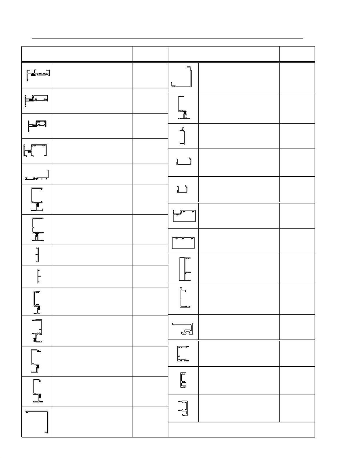
SECTION II - PARTS IDENTIFICATION CHART
PAGE 2
DESCRIPTION
STANDARD HEAD
USE W/ 8314, 8326, FT46,
FT47
STANDARD INTERMEDIATE
HORIZONTAL
USE W/ 8314, 8323, 8326
STANDARD INTERMEDIATE
BLIND PASS HORIZONTAL
USE W/ 8315, 8323, 8325
STANDARD SILL
USE W/ 8324, 2G22
STANDARD SUBSILL
STANDARD JAMB
USE W/ 8310, 8324
STANDARD INTERMEDIATE
VERTICAL MULLION
USE W/ 8309, 8323, 8324
MULLION SNAP IN FILLER
STD. INT. VERT. & STRUCT. MULLION
USE W/ 8307, 8311, 8320, 8340
PERIMETER JAMB
OPEN BACK FILLER
USE W/ 8307, 8339
SHALLOW POCKET
EXPANSION MULLION HALF
USE W/ 8313, 8323
PART NO.
8300
8301
8302
8344
2G22
8307
8308
8309
8310
8312
90˚ OUTSIDE CORNER
"COVER"
USE W/8334
90˚ OUTSIDE CORNER
MULLION HALF
USE W/ ITSELF, 8324
90˚ OUTSIDE CORNER
SNAP IN FILLER
USE W/ 8334
1" GLASS STOP FOR HEAD
& INT. HORIZONTAL
USE W/ 8300, 8301, 8327, 8329,
8338, 8341
1" GLASS STOP FOR INT.
BLIND PASS HORIZONTAL
USE W/ 8302, 8337
STANDARD DOOR
HEADER
USE W/ 8323
C.O.C. DOOR HEADER
USE W/ 8316, 8317, 8328
DOOR JAMB
USE W/ 8309, 8316, 8317, 8324,
8328
TRANSOM LITE GLASS
STOP
USE W/ 8304, 8311, 8317,
8328
PART NO.DESCRIPTION
8333
8334
8342
8314
8315
8303
8304
8311
8316
DEEP POCKET EXPANSION
MULLION HALF
USE W/ 8312, 8324
90˚ INSIDE CORNER
FEMALE MULLION
USE W/ 8324, 8332, 9297
90˚ INSIDE CORNER MALE
MULLION
USE W/ 8324, 8331, 9297
90˚ INSIDE CORNER
"COVER"
USE W/ 8331, 8332
8313
8331
8332
9297
TRANSOM LITE 1"
GLAZING BEAD
USE W/ 8316
STRUCTURAL GLAZED
MULLION
USE W/ 8309, 8327, 8330, EY83
STRUCTURAL GLAZED
EXPANSION MULLION
FEMALE HALF
USE W/ 8468
STRUCTURAL GLAZED
EXPANSION MULLION
FEMALE HALF
USE W/ 8469
8317
8320
8469
8468
BAB 11/2000
Page 5
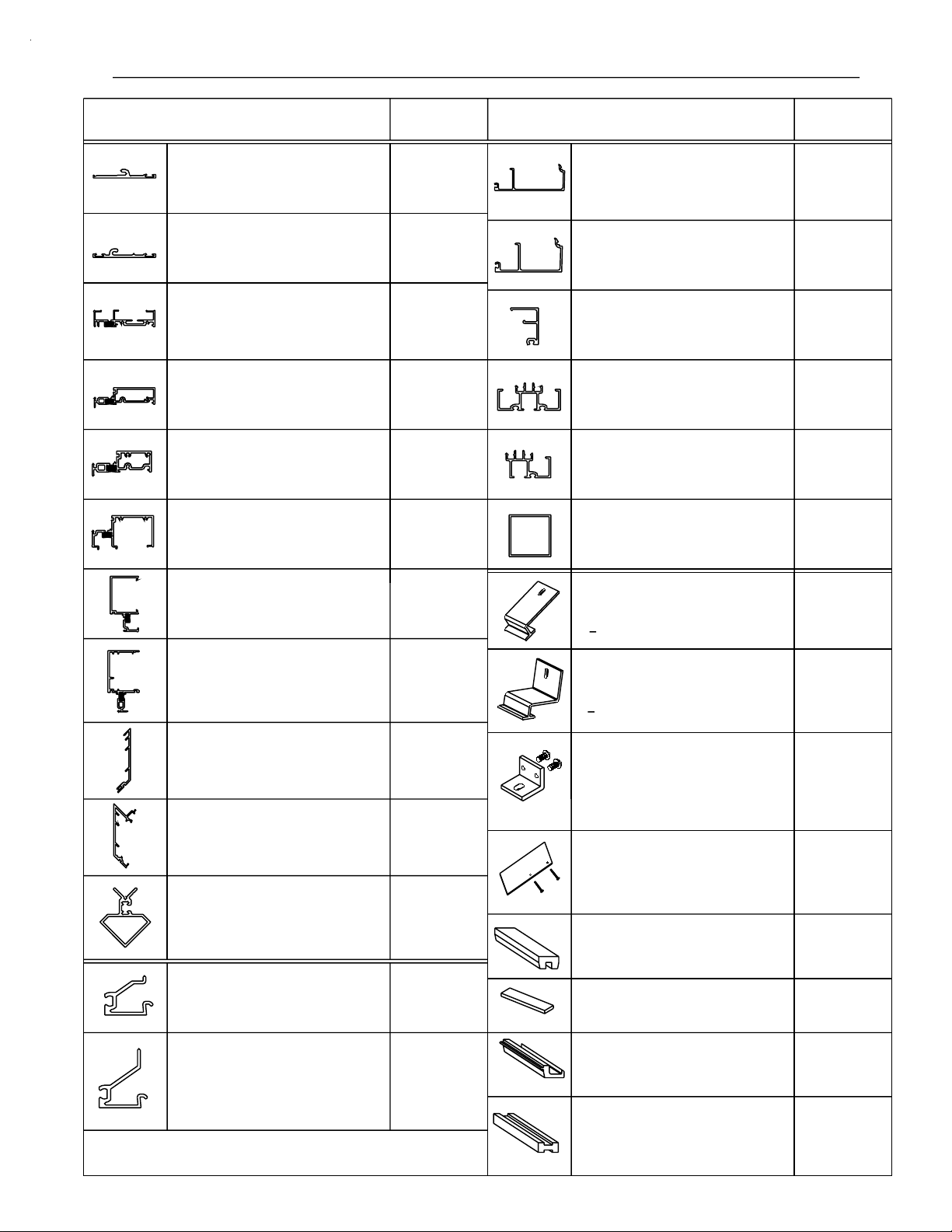
SECTION II - PARTS IDENTIFICATION CHART
PAGE 3
DESCRIPTION
TWO COLOR / STRUCT.
GLAZED FACE COVER
USE W/ 8329, 8338, 8339, 8343
TWO COLOR / STRUCT.
GLAZED FACE COVER
USE W/ 8337, 8340, 8341
STRUCT. GLAZED / TWO
COLOR STANDARD HEAD
USE W/ 8314, 8326, 8335, FT46,
FT47
STRUCT. GLAZED / TWO
COLOR INT. HORIZONTAL
USE W/ 8314, 8323, 8326, 8336
STRUCT. GLAZED / TWO
COLOR BLIND PASS INT.
HORIZONTAL
USE W/ 8315, 8323, 8325
STRUCT. GLAZED /
TWO COLOR SILL
USE/ 8324, 8335
8335
8336
8338
8341
8337
8343
DESCRIPTIONPART NO.
1/4" GLASS STOP FOR
INT. HORIZONTAL
USE W/ 8300, 8301, 8321,
8338, 8341
1/4" GLASS STOP FOR
BLIND PASS INT.
HORIZONTAL
USE W/ 8302, 8337
1/4" TRANSOM LITE
GLAZING BEAD
USE W/ 8316
1/4" GLAZING ADAPTER
FOR STRUCT. GLAZED
MULLION
USE W/ 8320
1/4" ADAPTER FOR 90˚
STRUCT. GLAZED
MULLION
USE W/ 8320, EY83
90˚ S.S.G. INSIDE
CORNER TUBE
USE W/ 8320
PART NO.
8326
8325
8328
8327
8330
EY83
STRUCT. GLAZED /
TWO COLOR JAMB
USE W/ 8324, 8335
TWO COLOR INT.
VERTICAL MULLION
USE W/ 8323, 8324, 8336
STRUCTURAL GLAZED 90˚
OUTSIDE CORNER
MULLION FEMALE HALF
USE W/ 8466, 8467
STRUCTURAL GLAZED 90˚
OUTSIDE CORNER
MULLION MALE HALF
USE W/ 8465, 8467
STRUCTURAL GLAZED 90˚
OUTSIDE CORNER COVER
USE W/ 8465, 8466
1/4" GLAZING
ADAPTER FOR
SHALLOW POCKET
8339
8340
8465
8466
8467
8323
"L" SHAPED ANCHOR
STRAP @ HEAD
> 36" D.LO. = 2 ANCHORS REQ.
< 36" D.L.O. = 3 ANCHORS REQ.
"Z" SHAPED ANCHOR
STRAP @ HEAD
> 36" D.L.O. = 2 ANCHORS REQ.
< 36" D.L.O. = 3 ANCHORS REQ.
VERTICAL ANCHOR
PACKAGE
USES FT68, MPD2
USE @ SILL END OF VERT.
MULLIONS FOR H.D. ANCHORS
SUBSILL END DAM
PACKAGE
INCLUDES FT48,SLQ1
USE W/ 2G22
1" SILL SETTING
BLOCK
1" SETTING BLOCK
FT46
FT47
K473
K458
HN37
HEP1
1/4" GLAZING
ADAPTER FOR DEEP
POCKET
8324
1/4" SILL SETTING
BLOCK
APPLIED TRANSOM
SETTING BLOCK
HN36
HN38
DPS 8/2001
Page 6
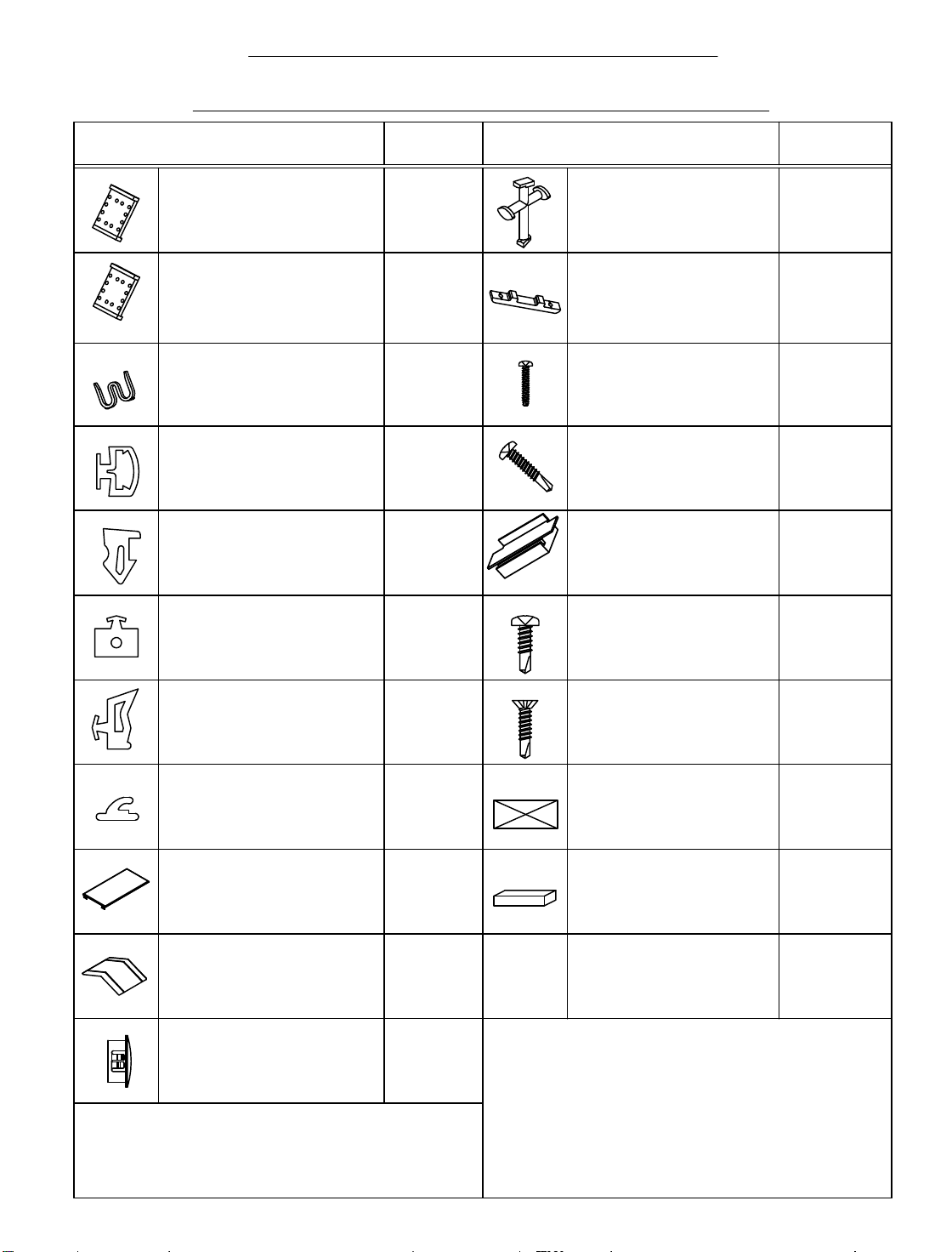
SECTION II - PARTS
IDENTIFICATION CHART
PAGE 4
DESCRIPTION
CAPTURED VERTICAL
FILLER / MULL IO N
DRILL FIXTURE
STRUCTURAL GLAZ ED
VERTICAL FILLER /
MULLION DRILL
FIXTURE
1/2" ANTIWALK
BLOCK
EXTERIOR
GLAZING
GASKET FOR
INSIDE GLAZED
INTER IOR GASKET FOR
INSID E GLAZED /
EXTERIOR GASKET FOR
OUTSIDE GLAZED
INTERIOR STRUCTURAL
GLAZED GLAZING
GASKET @ STRUCTURAL
MULLION
PART
NO.
DJ04
DJ05
HN50
WC12
W160
WEP0
DESCRIPTION
S.S.G. TEMPORARY
RETAINER
USED W/ SSG MULLIONS
SPACER SHIM FOR
DORMA R.T.S. 88
CONCEALED OVERHEAD
CLOSURE
#12-14 X 1 1/4"
PL-PH-SMS 18- 8
TYPE 25
ASSEMBLY SCREW
#10-16 X 1"
PL-PH-SMS SG TEK 3
MISC. F A STENER
S.S.G. INTERMEDIATE
HORIZONTAL BRIDGE
(USES FT77 AND HB99)
#8-18 X 9/16"
PL-PH-SMS ZC TEK/2
MISC. F A STENER
PART
NO.
HGR1
FT71
STC8
SLQ8
K483
STT6
INTERIOR GLAZING
GASKET FOR OUTSIDE
GLAZED
WEATHER SEAL
GASKET @ EXPANSION
MULLIONS
VERTICAL MULLION
CAULK BACKER /
SECONDARY WATER
END CAP @ HEAD
WATER
DEFLECTOR @
INT. HORIZONTAL
HOLE PLUG FOR
3/4" ACCESS
HOLE @ DOOR
JAMB
WNE0
W104
HEC1
HWD1
IM09
#8-18 X 3/4"
PL-FH- SMS 410 TEK/2
MISC. F A STENER
SETTING BLOCK
(FOR 1/4" GLAZING)
WEEP BAFFLE
USED @ SUB SILL
BOND BREAKER TAPE
USED @ SUB SILL SPLICES
4" X .062"
SLQ8
HDR6
HCW3
WM01
JWH
5/6/2014
Page 7
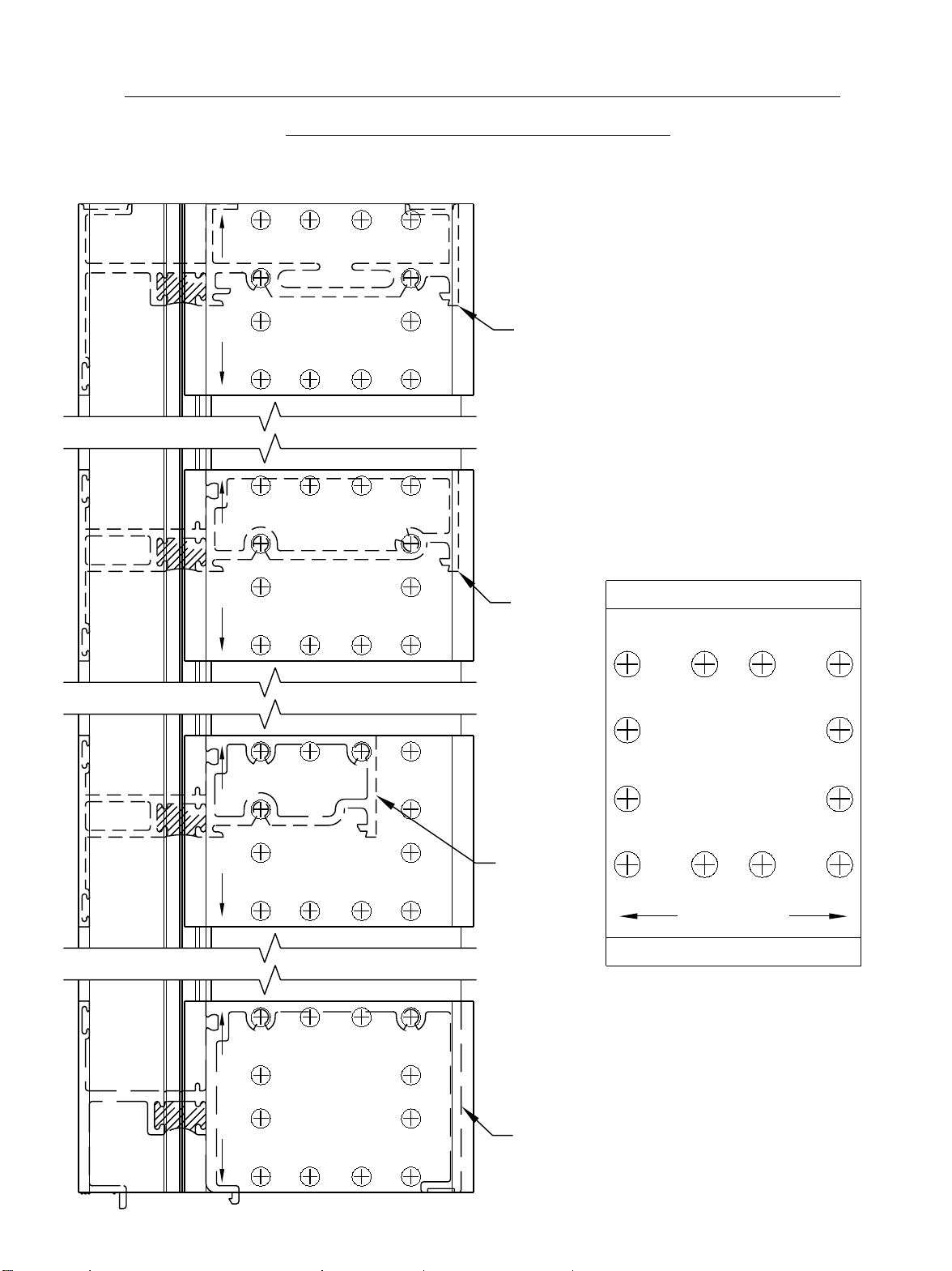
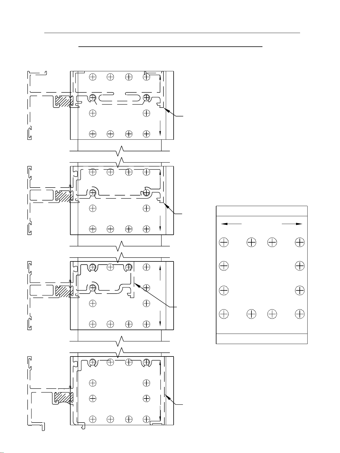
SECTION III A - DRILLING TEMPLATE FOR
CAPTURED MULLIONS
LEFT HAND STANDARD INT. VERTICAL (8308) SHOWN. RIGHT HAND OPPOSITE.
PAGE 5
B C
LH
RH
LH
RH
#2 DRILL
B C
A CCA
A C C A
B C
#2 DRILL
B C
(2)
(2)
DJO4
DJO4
F945
F945
ACA C
B
B
USE SIDE #2 OF JIG FOR FABRICATION
OF CAPTURED MULLIONS.
8300
USE THE INTERIOR SIDE OF THE GLASS
POCKET EDGE TO ALIGN JIG. MAKE
SURE THAT THE FABRICATION HOLES
ARE IN THE CORRECT POSITION BEFORE
DRILLING.
B
B
A C A C
8301
B
A
B
A C A C
F945
C
DJO4
LH
LH
A C
B C
#2 DRILL
RH
B C
A CCA
A C
B C
#2 DRILL
RH
B C
A C
(2)
(2)
C
DJO4
F945
C
DJO4
F945
CA
A
B
(2)
#2 DRILL
B C
B
8302
A C
B C
RH
LH
A = SILL HOLE LOCATIONS
A
B
B = HEAD AND INTERMEDIATE
HORIZONTAL HOLE
LOCATIONS
B
8344
C = BLIND PASS HORIZONTAL
HOLE LOCATIONS
BAB 11/2000
Page 8
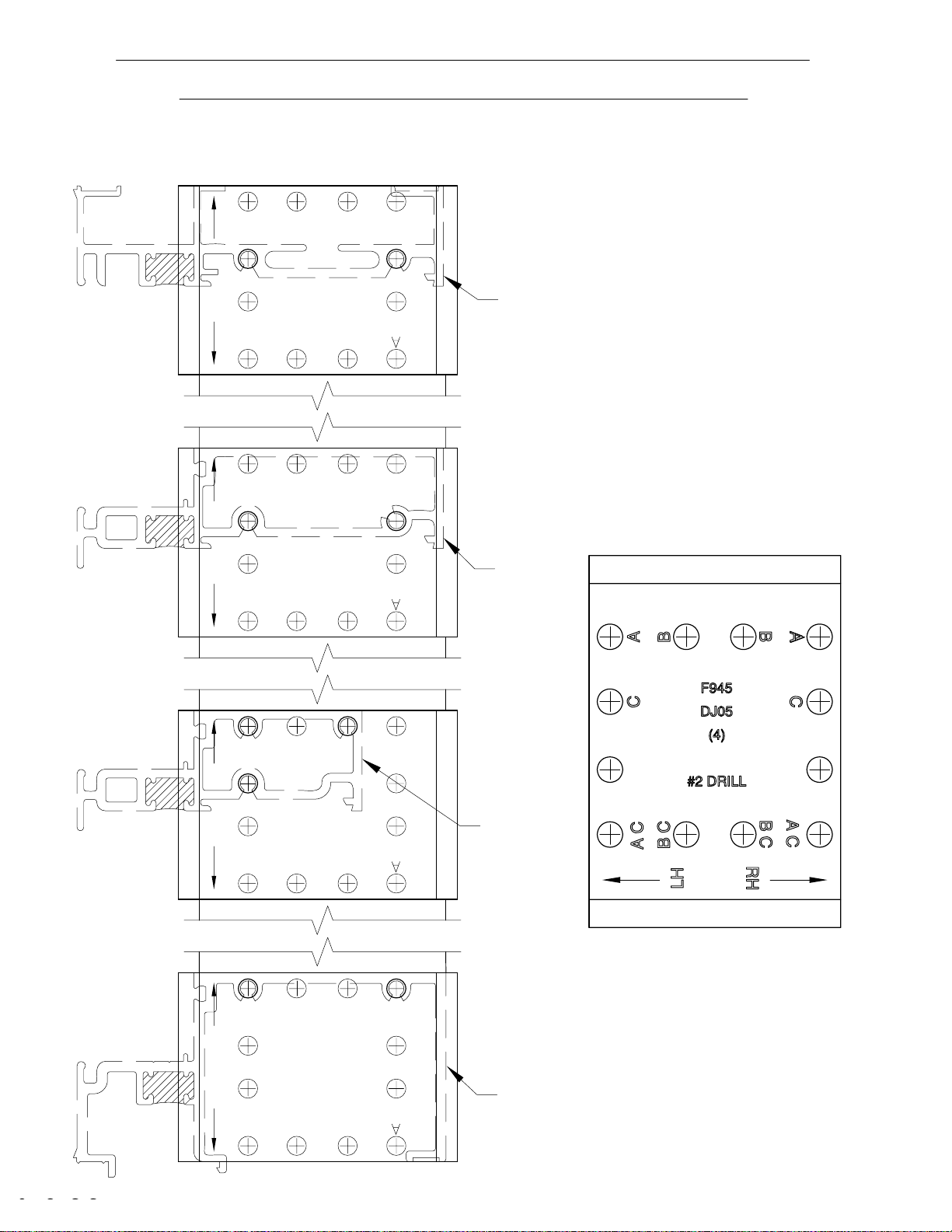
SECTION III B - DRILLING TEMPLATE FOR
CAPTURED MULLION FILLERS
LEFT HAND MULLION FILLER (8309) SHOWN. RIGHT HAND OPPOSITE.
PAGE 6
A C C A
B C
#2 DRILL
B C
A C C A
B C
#2 DRILL
B C
A C
(1)
(1)
DJO4
F945
DJO4
F945
CA
USE SIDE #1 OF JIG FOR FABRICATION
B
LH
RH
B
A C A C
OF CAPTURED MULLION FILLERS.
8300
USE THE EXTERIOR EDGE OF FILLER TO
ALIGN JIG. MAKE SURE THAT THE
FABRICATION HOLES ARE IN THE
CORRECT POSITION BEFORE DRILLING.
B
LH
RH
B
8301
RH
LH
B
B
A C
B C
#2 DRILL
B C
A CCA
A C
B C
#2 DRILL
B C
A CC
(1)
(1)
C
DJO4
C
DJO4
F945
F945
F945
CA
A
B
LH
DJO4
(1)
CA
#2 DRILL
RH
B
8302
A C
B C
B C
A C
A = SILL HOLE LOCATIONS
A
B
LH
B = HEAD AND INTERMEDIATE
HORIZONTAL HOLE
LOCATIONS
RH
B
A
8344
C = BLIND PASS HORIZONTAL
HOLE LOCATIONS
BAB 11/2000
Page 9
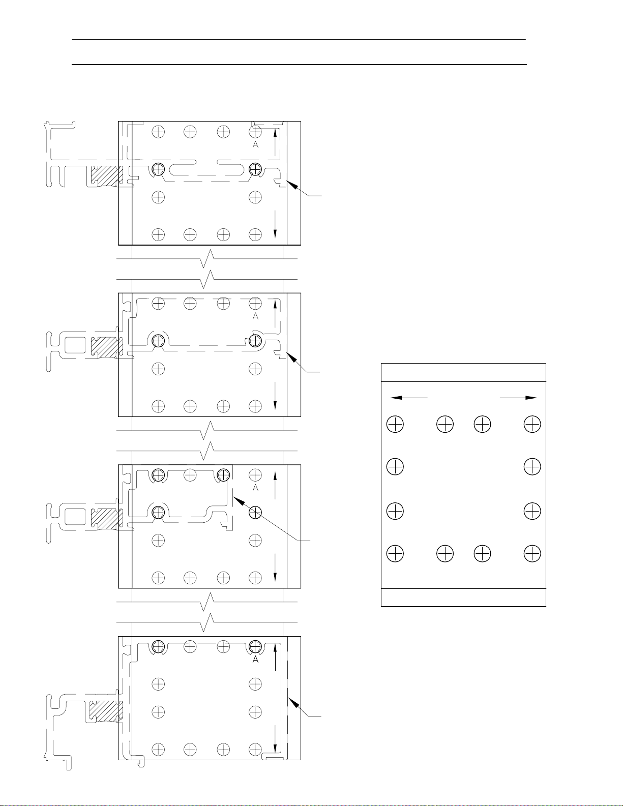
SECTION III C - DRILLING TEMPLATE FO R
STRUCTURAL GLAZED MULLIONS
LEFT HAND STRUCTURAL GLAZED MULLION (8320) SHOWN. RIGHT HAND OPPOSITE.
PAGE 7
LH
LH
RH
RH
A C
B C
A C
B C
B C
A C
B C
A C
CA
#2 DRILL
DJ05
(4)
B
F945
USE SIDE #4 OF JIG FOR FABRICATION
OF STRUCTURAL GLAZED MULLIONS.
8300
B
C
A
USE THE EXTERIOR EDGE TO ALIGN JIG.
MAKE SURE THAT THE FABRICATION
HOLES ARE IN THE CORRECT POSITION
BEFORE DRILLING.
AC
#2 DRILL
DJ05
(4)
B
F945
B
C
A
8301
LH
LH
RH
RH
A C
B C
A C
B C
B C
A C
B C
A C
C
#2 DRILL
DJ05
(4)
A
B
F945
B
C
A
8302
A = SILL HOLE LOCATIONS
B = HEAD AND INTERMEDIATE
C
#2 DRILL
DJ05
(4)
A
HORIZONTAL HOLE
B
F945
LOCATIONS
C = BLIND PASS HORIZONTAL
B
C
A
8343
HOLE LOCATION
Page 10
SECTION III D - DRILLING TEMPLATE FO R
STRUCTURAL GLAZED MULLION FILLERS
LEFT HAND STRUCTURAL GLAZED MULLION FILLER (8309) SHOWN. RIGHT HAND OPPOSITE.
PAGE 8
A C C
B C
A C C
B C
#2 DRILL
(3)
B C
A C
#2 DRILL
(3)
B C
A C
DJ05
F945
CA
DJ05
F945
CA
A
B
LH
OF STRUCTURAL G LAZED MULLION
FILLERS.
USE SIDE #3 OF JIG FOR FABRICATION
RH
B
8300
USE THE EXTERIOR EDGE OF FILLER TO
ALIGN JIG. MAKE SURE THAT THE
FABRICATION HOLES ARE IN THE
CORRECT POSITION BEFORE DRILLING.
A
B
LH
RH
B
8301
RH
LH
B
A
B
A
A C
B C
A C
B C
B C
A C
B C
A C
F945
B C
C
A C
C
C
#2 DRILL
(3)
DJ05
F945
CA
A
B
LH
RH
B
8302
A C
DJ05
(3)
#2 DRILL
B C
A = SILL HOLE LOCATIONS
B = HEAD AND INTERMEDIATE
C
#2 DRILL
(3)
A
B
DJ05
F945
LH
HORIZONTAL HOLE
LOCATIONS
C = BLIND PASS HORIZONTAL
8343
HOLE LOCATION
CA
RH
B
Page 11
PAGE 9
SECTION IV - UNIT ASSEMBLY
INCLUDES CAPTURED AND STRUCTURAL GLAZED MULLION SYSTEMS
STEP 1) GENERAL NOTES
A. Ensure that all tooling is correct before assembly. For each D.L.O. there
should be a deep pocket and a shallow pocket. If only one D.L.O. is required,
both pockets will be deep. The glass will not be able to be loaded with two
shallow pockets. Also, keep all deep pockets on center D.L.O.'s on the same
side of the D.L.O. See Fig. 1 below.
VERT.
JAMB
EXPANSION
MULLION
VERT.
MULLION
JAMB
8310
8307
HN50
WALK
BLOCK
OPTIONAL
8313
8312
DEEP
POCKET
SHALLOW
POCKET
8309
8308
DEEP
POCKET
SHALLOW
POCKET
8307
8310
DEEP
POCKET
[FIG. 1]
B. Check the fabrication to ensure that the vertical mullion and vertical mullion
filler are fabricated opposite of each other. If the mullion is fabricated for the
right, the filler should be fabricated for the left. The vertical expansion mullion
should be fabricated the same way. See Fig. 2 below.
FABRICATED
AS LEFT JAMB
FABRICATED
AS RIGHT
INTERMEDIATE
FABRICATED
AS LEFT
INTERMEDIATE
FABRICATED
AS RIGHT
INTERMEDIATE
FABRICATED
AS RIGHT
JAMB
945 QUICKSET
FABRICATED
AS LEFT
INTERMEDIATE
[FIG. 2]
KDE 11/2003
Page 12
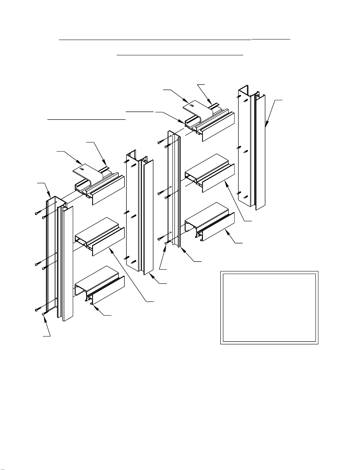
SECTION IV - UNIT ASSEMBLY (CON’T)
CAPTURED MULLION SYSTEMS
STEP 2) HORIZONTALS TO JAMB ASSEMBLY
HEAD
(8300)
FT46 (SHOWN)
FT47 (OPTION)
APPLY BUTYL TYPE SEALANT TO THE END
OF ALL THE HORIZONTALS BEFORE
ATTACHING TO THE JAMBS.
HEAD
ANCHOR
FT46 (SHOWN)
FT47 (OPTION)
(8300)
JAMB
(8307)
ANCHOR
PAGE 10
JAMB
(8307)
INT. HORIZONTAL
8301 - STANDARD
(8302 - OPTIONAL)
SILL
(8344)
VERT. MULLION FILLER
(8309)
STC8
GENERAL NOTE: If the D.L.O.
is 36" wide or less, 2 strap
anchors are required. D.L.O.’s
greater than 36" require 3
anchors. Anchor widths and
locations should be verified by
a structural engineer for job
specific conditions.
STC8
SILL
(8344)
VERTICAL INT.
8308
INT. HORIZONTAL
8301 - STANDARD
(8302 - OPTIONAL)
[FIG. 3]
Apply butyl type sealant to the ends of all horizontal members. Before assembly, apply wax
lubricant to all STC8 fasteners. Fasten one end of the horizontals to the vertical member.
Install anchors into the head. Fasten the opposite vertical member to all horizontal members.
Make sure that butyl type sealant has been applied to that end of the horizontal members.
Wipe off all excess sealant.
To ensure that the unit will assemble correctly, verify that the intermediate verticals and the
fillers are fabricated opposite of each other.
If strap anchors are to be used, slide them into the head before assembling the ladder.
NOTE: For inside glazed systems, install exterior glazing gasket (WC12) prior to assembly.
For outside glazed systems, install interior glazing gasket (WNE0) prior to assembly of units.
BAB 11/2000
Page 13
PAGE 11
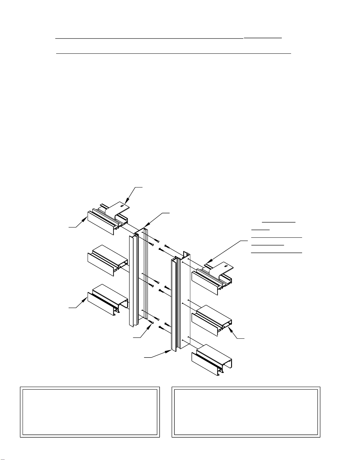
SECTION IV - UNIT ASSEMBLY
(CON’T)
CAPTURED AND STRUCTURAL GLAZED MULLION SYSTEMS
STEP 3) HORIZONTALS TO EXPANSION MULLION
ASSEMBLY
(CAPTURED SYSTEM SHOWN, STRUCTURAL GLAZED SYSTEM SIMILAR)
To ensure that the unit will assemble correctly, verify that the expansion mullion
halves are fabricated opposite of each other. See Fig. 4. Apply butyl type sealant to the
ends of all horizontal members that come in contact with the expansion mullion. Install
anchors into the head. Before assembly, apply wax lubricant to all STC8 fasteners.
Fasten the expansion mullion to all horizontal members. Fasten the other vertical mullion,
jamb, etc. to the other end of the horizontals. Make sure that you have applied butyl type
sealant to the other ends of the horizontal members. Wipe off all excess sealant.
ANCHOR
FT46 (SHOWN)
HEAD
(8300)
FT47 OPTIONAL
EXPANSION MULLION
HALF (SHALLOW
POCKET)
(8312)
APPLY BUTYL
TYPE SEALANT
TO THE AREA
THAT
CONTACTS THE
VERTICAL
MULLION FILLER
BEFORE
ATTACHING TO
THE EXPANSION
MULLION.
SILL
(8344)
STC8
EXPANSION MULLION
HALF (DEEP POCKET)
(8313)
NOTE: For inside glazed systems, install
exterior glazing gasket (WC12) prior to
assembly. For outside glazed systems,
install interior glazing gasket (WNE0) prior
to assembly of units.
INT. HORIZONTAL
8301 - (SHOWN)
8302 - OPTIONAL
[FIG. 4]
GENERAL NOTE: If the D.L.O. is 36" wide or less, 2
strap anchors are required. D.L.O.’s greater than 36"
require 3 anchors. Anchor widths and locations
should be verified by a structural engineer for job
specific conditions.
BAB 11/2000
Page 14
PAGE 12
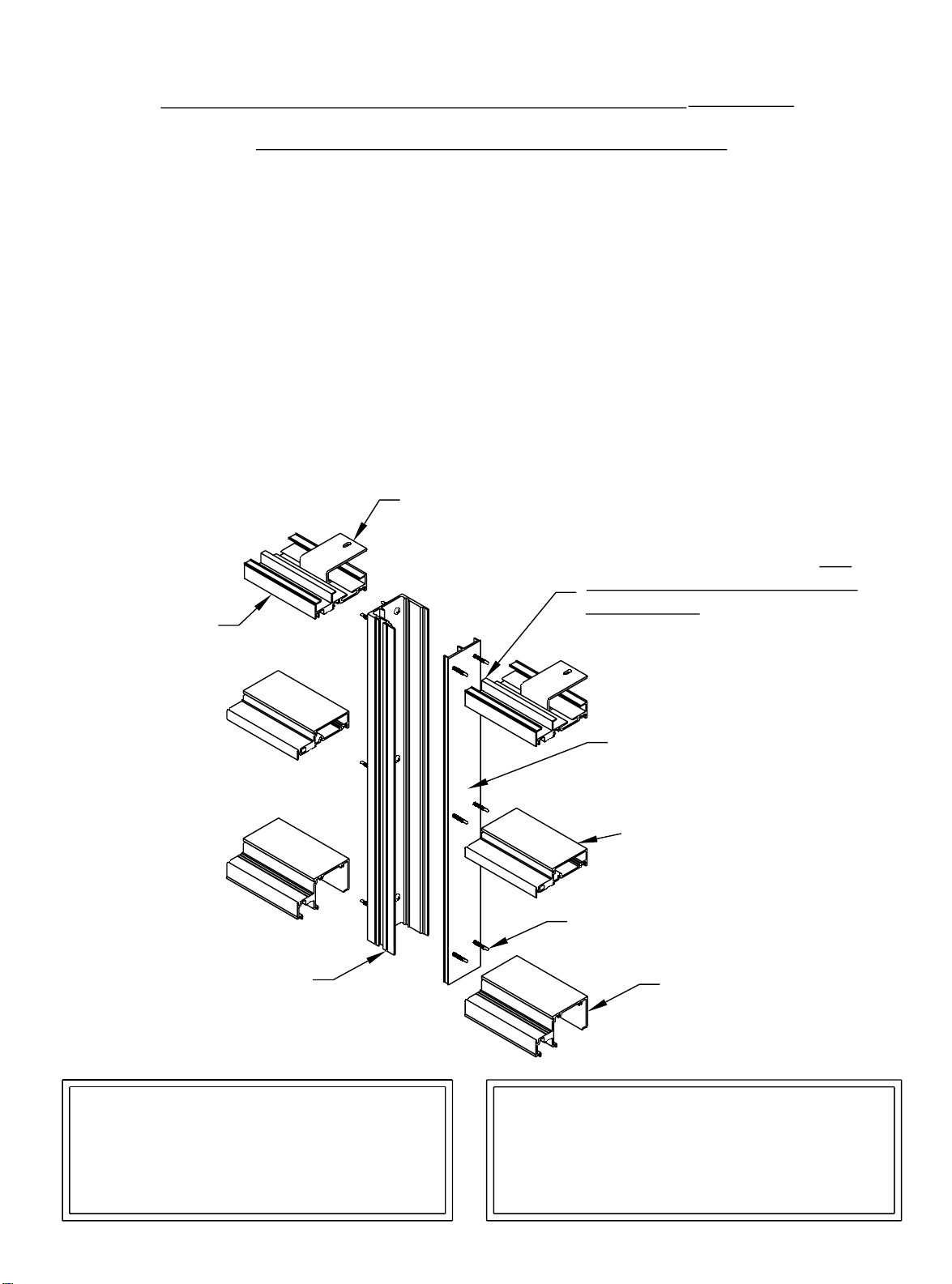
SECTION IV - UNIT ASSEMBLY
(CON’T)
STRUCTURAL GLAZED MULLION SYSTEMS
STEP 4) STRUCTURAL GLAZED SYSTEM ASSEMBLY
To ensure that the unit will assemble correctly, verify that the structural glazed mullion
and filler are fabricated opposite of each other. Apply butyl type sealant to the end of all
horizontal members that come into contact with the structural glazed mullion. Install
anchors into the head. Before assembly, apply wax lubricant to all STC8 fasteners.
Fasten the structural glazed mullion to all horizontal members. Fasten the opposite
vertical mullion, jamb, etc. to the other end of the horizontals. Make sure that butyl type
sealant has been applied to the other ends of the horizontal members. Ensure that
anchor straps have been installed if required. Wipe off all excess sealant.
ANCHOR
FT46 (SHOWN)
FT47 OPTIONAL
APPLY BUTYL TYPE SEALANT TO THE
AREA THAT CONTACTS THE VERTICAL
HEAD
(8338)
MULLION FILLER BEFORE ATTACHING
TO THE VERTICAL MULLION FILLER.
STRUCTURAL GLAZED
MULLION
(8320)
[FIG. 5]
NOTE: For inside glazed systems, install
exterior glazing gasket (WC12) prior to
assembly. For outside glazed systems,
install interior glazing gasket (WNE0) prior
to assembly of units.
MULLION SNAP-IN
FILLER
(8309)
INT. HORIZONTAL
8341 (SHOWN)
8337 OPTIONAL
STC8
SILL
(8343)
GENERAL NOTE: If the D.L.O. is 36" wide or less, 2
strap anchors are required. D.L.O.’s greater than 36"
require 3 anchors. Anchor widths and locations
should be verified by a structural engineer for job
specific conditions.
BAB 11/2000
Page 15
PAGE 13
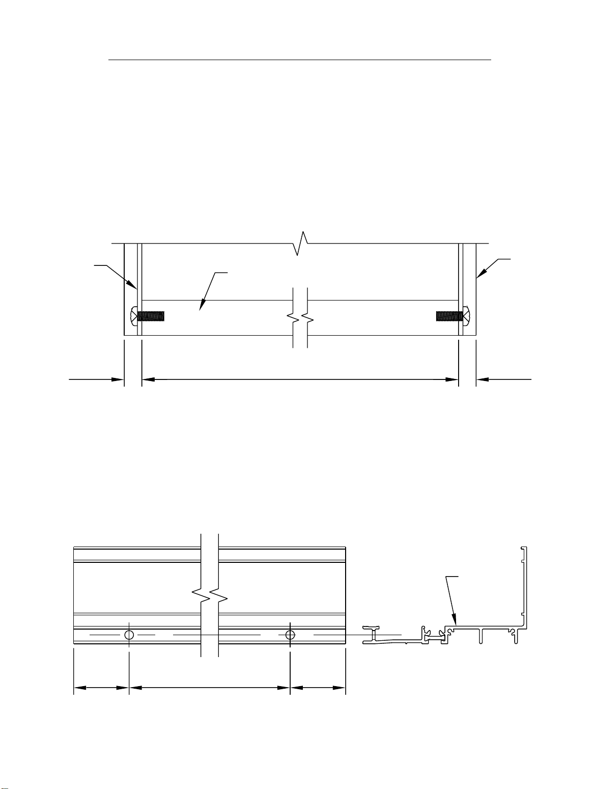
SECTION V - SUBSILL FABRICATION
INCLUDES CAPTURED AND STRUCTURAL GLAZED MULLION SYSTEMS
STEP 1) CUT LENGTH
Measure the opening to determine the cut length of the subsill.
Subtract 1/4" for the width of the end dam and fastener head from
the rough opening for each end. Cut the subsill to the determined length.
CUT LENGTH = R.O. - 1/2"
K458
END DAM
1/4"
SUBSILL
2G22
ROUGH OPENING - 1/2"
STEP 2) WEEP FABRICATION
Drill 5/16" weep holes in the subsill 6" from jambs and no more than
42" apart.
+1/8"
- 0
ROUGH
OPENING
1/4"
[FIG. 6]
6" 42" MAXIMUM O.C.
SUBSILL
2G22
6"
[FIG. 7]
BAB 11/2000
Page 16

PAGE 14
SECTION V - SUBSILL FABRICATION
(CON'T)
INCLUDES CAPTURED AND STRUCTURAL GLAZED MULLION SYSTEMS
STEP 3) BAFFLE FABRICATION
Weep baffles are cut from (1) HCW6, halved. This provides (2)
weep baffles per HCW6. See Fig. 8 below.
3/8"
1/2"
2"
1/2"
3/4"
2"
HCW6
[FIG. 8]
STEP 4) WEEP BAFFLE INSTALLATION
Apply a small amount of silicone type sealant to the baffles, and locate
them over the weep holes.
-- DO NOT PLUG THE WEEP HOLES WITH SEALANT--
WEEP BAFFLE
2G22
SEALANT
WEEP BAFFLE
945 Quick Set DPS 8/2001
[FIG. 9]
Page 17

PAGE 15
SECTION V - SUBSILL FABRICATION
(CON’T)
INCLUDES CAPTURED AND STRUCTURAL GLAZED MULLION SYSTEMS
STEP 5) END DAM INSTALLATION
The end dam is to be attached to the subsill with 2 SLQ1 fasteners on
each end. Seal the end of the subsill with silicone sealant before
attaching the end dam to the subsill. Tool the sealant at the interior joint
of the end dam to ensure a good watertight seal. See Figure 10 below.
APPLY
SEALANT
TO ENDS
OF THE
SUBSILL
TOOL SEALANT
AT JOINT
BEFORE
ATTACHING
END DAM
2G22
K458
END DAM
SLQ1
[FIG. 10]
STEP 6) CHALK LINE FOR SUBSILL
Before installing the subsill, measure the distance from the exterior of
the condition to the desired location at the EXTERIOR of the subsill. (The
exterior of the subsill will be flush with the rest of the system.) Do this at
both ends of the condition. Snap a chalk line between the two marks to
align the subsill. If the condition is too wide for just two marks, measure
every 15 feet and snap a chalk line.
BAB 11/2000
Page 18

SECTION V - SUBSILL FABRICATION (CON’T)
INCLUDES CAPTURED AND STRUCTURAL GLAZED MULLION SYSTEMS
PAGE 16
STEP 7) SEALANT BED
Apply sealant to the subsill as shown in
Figure 11. Place the subsill into the rough
opening, and rotate the exterior face down
into position. Apply enough sealant to
ensure a complete seal as shown in
Figure 12.
SEALANT
SUBSILL
2G22
CONDITION
SUBSILL
2G22
Wipe off any excess sealant from the exterior of the subsill.
SEALANT
[FIG. 11]
SUBSILL
2G22
[FIG. 12]
BAB 11/2000
Page 19

PAGE 17
SECTION V - SUBSILL FABRICATION (CON’T)
INCLUDES CAPTURED AND STRUCTURAL GLAZED MULLION SYSTEMS
STEP 8) SUBSILL ANCHOR INSTALLATION
At a minimum, anchor at 6" from jambs and corners, (1) on each side
of vertical mullions, and 24" O.C. between verticals. These are general
guidelines. Size fasteners as required to meet structural loads.
K473 HD ANCHOR
(OPTIONAL)
(FASTENERS NOT
SUPPLIED BY EFCO)
3"±
[FIG. 13]
8308
SUBSILL
2G22
[FIG. 13A]
3/4"
For standard applications utilize anchorage shown in Figure 13. If
heavy-duty anchorage is required, refer to the location of K473 heavy-duty
anchor as shown in Figure 13A.
3" ±
6"
24" O.C.
MAX.
24" O.C.
MAX.
[FIG. 14]
6" 6"
BAB 11/2000
Page 20

PAGE 18
SECTION V - SUBSILL FABRICATION
(CON’T)
INCLUDES CAPTURED AND STRUCTURAL GLAZED MULLION SYSTEMS
STEP 9) SUBSILL ANCHOR SEAL
The subsill anchor must be sealed with a silicone type sealant. To
ensure a good seal, tool the sealant onto the fastener.
SILICONE TYPE SEALANT
SUBSILL
2G22
[FIG. 15]
STEP 10) SUBSILL PERIMETER SEAL
The subsill interior should be sealed with a silicone type sealant.
Apply sealant and tool the sealant to ensure a good seal. Clean off all
excess sealant. At this time, use a silicone type sealant to seal the
thermal break area as shown in Figure 16. Tool the sealant into the
thermal break area, and ensure that the sealant does not interfere with
the subsill anchor leg notch. See Detail "A."
SUBSILL
ANCHOR
LEG
SILICONE
TYPE
SEALANT
SUBSILL
2G22
[FIG. 16]
SILICONE
TYPE
SEALANT
DETAIL "A"
BAB 11/2000
Page 21

PAGE 19
SECTION V - SUBSILL FABRICATION
(CON’T)
INCLUDES CAPTURED AND STRUCTURAL GLAZED MULLION SYSTEMS
STEP 11) SUBSILL SPLICING
Verify that the subsill has been installed according to the instructions on Pages 9
through 14. Splice areas are to be centered at a vertical mullion only. Maximum
subsill length between splices is 20’. If a splice is required, leave a 1/4" gap between
the subsill ends at the splice area. Install and anchor the next run of subsill. Use a
silicone type sealant and a strip of, WM01, bond breaker tape 2" wide and
approximately 7 3/4" long to create the splice material. Apply silicone to both sides
of the subsill ends and fill the void between the subsills as shown in Figure 17.
Ensure that the bond breaker tape is centered over the 1/4" gap, and set the bond
breaker tape into the sealant. Tool the silicone over the bond breaker tape to create
a water tight seal. If more sealant is required to cover the bond breaker tape, apply
the required amount. Ensure that the splice joint does not interfere with the anchor
legs of the sill and subsill. This is done by making sure that the splice joint is located
at the center of the vertical mullions. Refer to the shop drawings or architectural
drawings for mullion center lines.
APPLY SILICONE TYPE
SEALANT TO CREATE A
THIN BED TO SET THE
BOND BREAKER TAPE
INTO.
[FIG. 17]
SUBSILL
2G22
SUBSILL
2G22
FILL VOID BETWEEN
SUBSILLS WITH A SILICONE
TYPE SEALANT FROM THE
INTERIOR LEG TO THE BACK
OF THE EXTERIOR LEG.
AFTER INSTALLING THE BOND BREAKER TAPE,
TOOL THE SEALANT OVER THE EDGE OF THE TAPE
TO PRODUCE A WATER TIGHT SEAL.
AFTER THE SPLICE IS INSTALLED, APPLY
A COSMETIC SEAL TO THE INTERIOR
GAP, VERTICALLY.
945 Quick Set
BAB 11/2001
Page 22

SECTION V - SUBSILL FABRICATION (CON’T)
INCLUDES CAPTURED AND STRUCTURAL GLAZED MULLION SYSTEMS
STEP 12) SUBSILL CORNER MITER AND SPLICING
When mitering the subsill for corner applications, cut the subsill material at the
appropriate angle required to form the correct corner. Install the subsill by following
the previous subsill installation instructions. Once the subsill is installed and a tight
miter joint is achieved, use the instructions on Page 19 for creating a splice joint seal.
Ensure that the bond breaker tape and sealant used to create the seal are smooth,
so they do not interfere with the anchor legs on the sill and subsill.
PAGE 20
SUBSILL
2G22
[FIG. 18]
BAB 11/2000
Page 23

PAGE 21
SECTION VI - CORNERS
CORNER IDENTIFICATION AND ASSEMBLY
Proper identification of the required corner members is necessary to ensure a timely
installation process.
1) 90˚ captured outside corner
2) 90˚ captured inside corner
3) 90˚ S.S.G. inside corner
4) 90˚ S.S.G. outside corner
5) 135˚ S.S.G. outside corner
Determine that the subsill has been installed according to the instructions listed on Pages 13
through 20. Assemble the appropriate extrusions to create the required corner member.
Utilize the fasteners shown in Figures 19 through 21A on Pages 21 and 22. The fasteners
should be installed 6" from each end and 12" on center. Install the appropriate assembled
corner member into the subsill. It may be necessary to temporarily brace the vertical corner
member until the adjacent ladders are installed and anchored.
If door openings are required on a run that incorporates a corner member, begin at the door
frame and assemble towards the corner area with the required ladders. Unassembled
corner extrusions must be attached to the ladders, and the corner member must be
assembled after installation of both adjacent ladders.
8334
S
8334
W160
WC12
W160
S
STC8
STK8
STK8
8342
8333
S
WC12
W160
8332
WC12
STC8
9297
S
S
STK4
S
STC8
[FIG. 19]
WC12
8331
W160
DPS 04/2001
Page 24

SECTION VI - CORNERS (cont.)
PAGE 22
CORNER IDENTIFICATION AND ASSEMBLY
8320
STC8
STT6
STT6
WEP0
8309
STC8
[FIG. 20]
STT6
STC8 STC8
(CON’T)
EY83
STT6
8320
WEP0
8309
8466
WEP0
8467
STT6
STC8
WEP0
8465
WEP0
[FIG. 21]
2G69
STC8
8309
STC8
STC8
8309
WEP0
STC8
[FIG. 21A]
DPS 04/2001
Page 25

PAGE 23
SECTION VII - DOOR FRAME INSTALLATION
STEP 1) GENERAL NOTES
If a door opening is required, the subsill must be installed into the opening from the door
framing, ensuring that the appropriate clearance is available for the door frame. All
subsequent ladders must be installed from the door jamb out.
INSTALL 1ST
(AFTER SUBSILL)
1 3/16"
1 3/16"
SUBFRAME CLEARANCE HOLE =
[DOOR OPENING WIDTH + 2 3/8"]
[FIG. 22]
STEP 2) SUBSILL INSTALLATION AT DOOR OPENING
Where a door opening is required, use the equation in Figure 22. Install the subsill in
the same manner as illustrated on Pages 13 through 20, leaving the appropriate
clearance in the subsill for all door framing. End dams are not required at the door
frame end of the subsill. See Figure 23 on Page 24 for subsill sealant requirements at
door framing.
BAB 11/2000
Page 26

PAGE 24
SECTION VII - DOOR FRAME INSTALLATION
(cont.)
STEP 3) SUBSILL SEALANT AT DOOR FRAME
Before installing the door frame to the subsill, seal the end of the subsill with a silicone type
sealant. Install the door frame, and tool all excess sealant into the joint. If required, add
more sealant to create a smooth water tight seal.
DOOR FRAME
1/2"
NOTCH FOR
SUBSILL
SEALANT
SUBSILL
[FIG. 23]
BAB 11/2000
Page 27

PAGE 25
SECTION VIII - INSTALLATION
INCLUDES CAPTURED AND STRUCTURAL GLAZED MULLION SYSTEMS
STEP 1) SEALING THE SILL ONTO THE SUBSILL
Apply a silicone type sealant to the subsill in the location shown in Figure 24
before installing the first ladder. Make sure that enough sealant is applied to seal
the areas shown in Figure 25. After installing the ladder and anchoring it, clean off all
excess sealant.
SEALANT
2G22
SEALANT
[FIG. 24]
8344
2G22
SEALANT
SEALANT
[FIG. 25]
BAB 11/2000
Page 28

PAGE 26
SECTION VIII - INSTALLATION (CON’T)
INCLUDES CAPTURED AND STRUCTURAL GLAZED MULLION SYSTEMS
STEP 2) INSTALLING JAMB SIDE LADDER
Make sure that the anchors are installed into the head. Place the ladder on the
subsill at an approximate 30˚ angle. While applying pressure upwards, rotate the
ladder into the condition. See Figure 25 on Page 25 for sill placement into the subsill.
When rotated correctly, the exterior face of the sill should be flush with the exterior
face of the subsill.
LADDER
CONDITION
[FIG. 26]
CONDITION
LADDER
[FIG. 27]
BAB 11/2000
Page 29

PAGE 27
SECTION VIII - INSTALLATION
(CON’T)
INCLUDES CAPTURED AND STRUCTURAL GLAZED MULLION SYSTEMS
STEP 3) ANCHORING THE HEAD
For D.L.O.’s 36" and narrower, the anchors must be spaced 6" from the jamb or
vertical members. For D.L.O.’s 36" and wider, the outside anchors must be spaced
6" from the jamb with the center anchor centered on the D.L.O. See Figure 28. If no
strap anchor is used, anchor the head as shown in Figure 29, and use the same
anchor spacing requirements. These are general anchoring guidelines. All actual
anchor requirements should be verified by a structural engineer.
6" "VARIES" 6"
EQUAL
6"
EQUAL
6"
FDFD
LESS THAN OR EQUAL 36"
FDFDFD
GREATER THAN 36"
[FIG. 28]
8300
[FIG. 29]
1 1/2
" REF.
BAB 11/2000
Page 30

PAGE 28
SECTION VIII - INSTALLATION (CON’T)
INCLUDES CAPTURED AND STRUCTURAL GLAZED MULLION SYSTEMS
STEP 4) ANCHORING THE JAMB
Anchors must be spaced 6" from the sill or head, and 24" O.C. ± 4", so they do
not interfere with the horizontal members. The size and type of anchors depend on
structural loads and surrounding condition. Anchors are not by EFCO.
6"
FD
8307
24" ± 4"24" ± 4"
24" ± 4"
6"
FD
FD
FD
[FIG. 31]
1/2"
REF
[FIG. 30]
BAB 11/2000
Page 31

PAGE 29
SECTION VIII - INSTALLATION
(CON’T)
INCLUDES CAPTURED AND STRUCTURAL GLAZED MULLION SYSTEMS
STEP 5) SEALING THE EXPANSION MULLION
If installing an expansion mullion, apply silicone type sealant in the locations
shown below. The interior should be sealed up 6" from the subsill, and the entire
exterior joint should be sealed. Apply enough sealant so that when the expansion
mullion is collapsed, it will squeeze the sealant out and create a good seal. Clean off
any excess sealant. See Figures 32 and 33.
SEAL 6" UP
SEALANT
FROM
SUBSILL
8469
8312
8313
SEALANT
8312
SEAL
ENTIRE
JOINT
SEAL ENTIRE
JOINT
8469
8468
[FIG. 32]
SEALANT
[FIG. 33]
STEP 6) SEALING THE INTERMEDIATE VERTICAL MULLION
SNAP IN FILLER
If installing an intermediate vertical mullion, apply silicone type sealant to the
intermediate vertical mullion in the locations shown below. Both sides of the entire
mullion should be sealed. Apply enough sealant so that when the filler is snapped, it
will create a good seal. Wipe off excess sealant. See Figures 34 and 35.
SEALANT
8308
[FIG. 34]
SEALANT
8308
[FIG. 35]
8309
SEALANT
BAB 11/2000
Page 32

PAGE 30
SECTION VIII - INSTALLATION
(CON’T)
INCLUDES CAPTURED AND STRUCTURAL GLAZED MULLION SYSTEMS
STEP 7) INSTALLING THE SECOND LADDER
(CAPTURED SYSTEM SHOWN, STRUCTURAL GLAZED SYSTEM SIMILAR)
Make sure that the anchors are installed into the head. Apply silicone type
sealant to the interior leg clip 6" from the subsill, and seal the entire exterior face as
shown in Figure 37. Apply sealant to the subsill as shown on Page 25. Place the
second ladder on the subsill at an approximate 30˚ angle. Rotate the ladder into the
condition approximately 1/4" away from the female expansion mullion half. See
Figures 36 and 38.
CONDITION
8312
SEAL
ENTIRE
JOINT
SEALANT 6" UP
FROM SILL END
APPROX. 1/4"
LADDER
[FIG. 36]
CONDITION
8313
[FIG. 37]
[FIG. 38]
LADDER
BAB 11/2000
Page 33

n
PAGE 31
SECTION VIII - INSTALLATION (CON'T)
INCLUDES CAPTURED AND STRUCTURAL GLAZED MULLION SYSTEMS
STEP 8) SNAPPING THE EXPANSION MULLION
(CAPTURED SYSTEM SHOWN, STRUCTURAL GLAZE D SYSTEM SIM IL AR )
To snap the expansion mullion together, line up the mullion halves and
gaskets. See Figure 39. Place one clamp at the bottom of the expansion
mullion using wood blocks to protect the extrusions. Tighten the C-clamp until
the expansion mullion halves begin to snap together. Place another set of
wood blocks and a C-clamp at the middle of the expansion mullion and tighten
it. Then repeat the same process on the top. Tighten the C-clamps until the
sight line becomes 2 1/2". It may be necessary to work from one clamp to the
next several times, or move the clamps, to ensure the mullions are snapped
together evenly. S ee Fig ure 40 . DO NOT try to hamme r the expansion mullio
together! This will dent, bend, scratch, or deform the expansion mullion and
may cause it to leak. Anchor the head using the requirements on Page 27
before installing the next ladder using the requirements on Page 30. If this is
the last ladder, anchor the jambs as required on Page 28 and proceed to the
perimeter sealing process, Step 11 on Page 33.
C-CLAMP
WOOD BLOCK
8313
8312
8312
WOOD BLOCK
8313
[FIG. 39]
[FIG. 40]
3-2009
Page 34

PAGE 32
SECTION VIII - INSTALLATION
(CON'T)
INCLUDES CAPTURED AND STRUCTURAL GLAZED MULLION SYSTEMS
STEP 9) SNAPPING THE SNAP-IN FILLER
To snap the snap-in filler, place the ladder in the subsill and align the snap-in
filler with the intermediate vertical, ensuring that the ladders are as tight together as
possible before continuing. Using a rubber mallet, gently tap the filler into place if
necessary. Work from the head to the sill, verifying that the ladder is completely
engaged before anchoring the head. See Figure 42.
8308
8308
945 QUICKSET
2 1/2"
[FIG. 41]
[FIG. 42]
8309
SEAL AS REQUIRED. SEE FIG.
34-35 PAGE 29.
8309
When completely snapped, the
filler should be flush with the
interior and exterior legs of the
vertical.
The same action is required for
structural glazed mullions also.
KDE 11/2003
Page 35

PAGE 33
SECTION VIII - INSTALLATION
(CON’T)
INCLUDES CAPTURED AND STRUCTURAL GLAZED MULLION SYSTEMS
STEP 10) ANCHORING THE SECOND LADDER
After the filler is snapped correctly, anchor the head and jamb as shown on
Pages 27 and 28.
STEP 11) PERIMETER SEAL
When the unit is installed and anchored, begin placing caulk rope into the gap
between the perimeter and the frame. Then apply a generous amount of silicone
type sealant to the gap between the frame and rough opening. Tool off all excess
sealant to ensure a good seal and to achieve an appropriate appearance. See
Figure 43.
SEALANT
8300
SEALANT
HEAD (W/ STRAP
ANCHOR)
[FIG. 43]
SEALANT
8307
JAMB
8300
FT46
SEALANT AROUND
ANCHOR AND AT
PERIMETER
SEALANT
HEAD (W/O STRAP
ANCHOR)
SEALANT
8310
The same action is required for outside glazed and
structural glazed mullions also. Make sure that the
face covers are installed prior to the perimeter seal
for these members. This step will be completed
after glass installation.
BAB 11/2000
Page 36

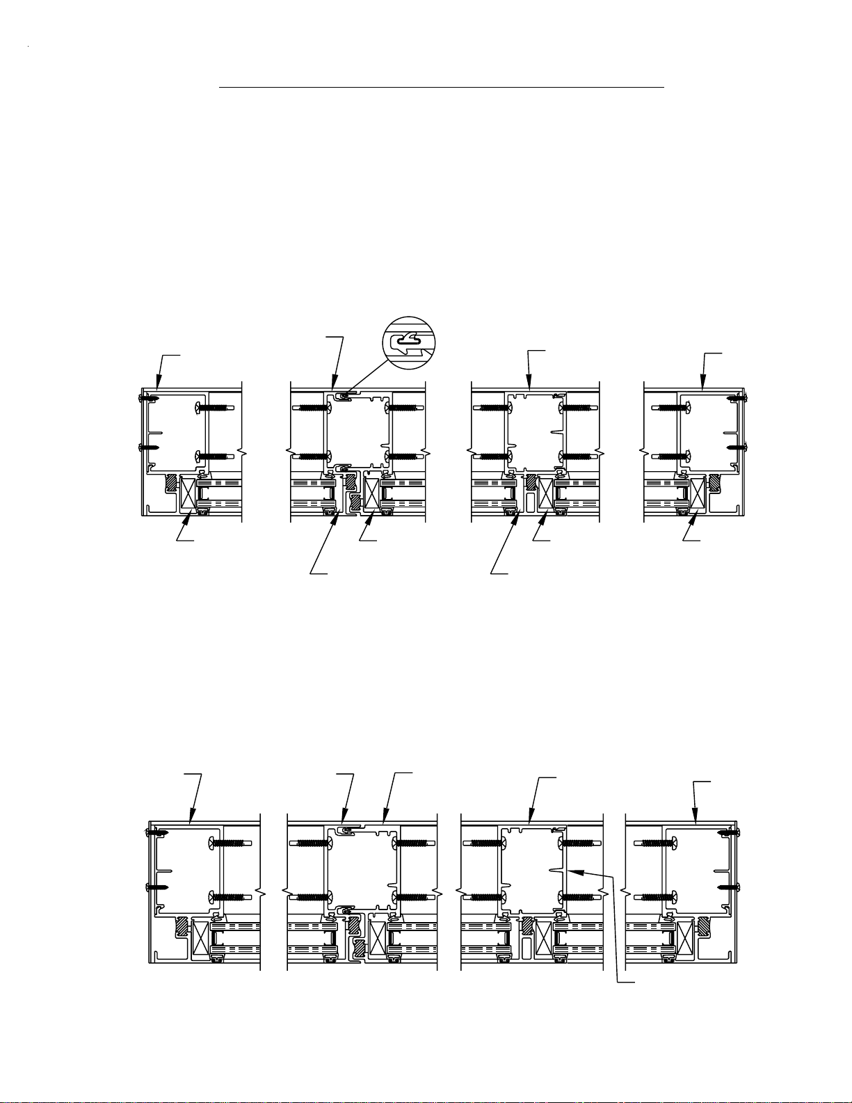
SECTION IX - GLAZING
FOR INSIDE GLAZED CAPTURED FRAMING SYSTEMS
STEP 1A) IDENTIFICATION OF GLASS POCKETS
1" GLAZING FOR INSIDE GLAZED CAPTURED FRAMING SYSTEM
TYP. VERTICAL
1" GLASS
1" GLASS
W160
W160
WC12
W160
PAGE 34
WC12
1" GLASS
WC12
TYP. 1"
GLASS
STOP
TYP. HORIZONTAL
WC12
W160
[FIG. 44]
1" GLASS
1/4" GLAZING FOR INSIDE GLAZED CAPTURED FRAMING SYSTEM
TYP. VERTICAL
1/4" GLASS
W160
8323
W160
8323
8324
W160
1/4" GLASS
HDR6
WC12
WC12
1/4" GLASS
WC12
TYP. HORIZONTAL
[FIG. 45]
WC12
TYP. 1/4"
GLASS
STOP
W160
1/4" GLASS
BAB 11/2000
Page 37

PAGE 35
SECTION IX - GLAZING
(cont.)
FOR OUTSIDE GLAZED AND STRUCTURAL GLAZED FRAMING SYSTEMS
STEP 1B) IDENTIFICATION OF GLASS POCKETS
1" GLAZING FOR OUTSIDE GLAZED AND STRUCTURAL SILICONE GLAZED
FRAMING SYSTEM
TYP. O.G. VERTICAL
1" GLASS
1" GLASS
WNE0
W160
1" GLASS
WNE0
W160
TYP. FACE COVER
TYP. FACE COVER
W160
W160
WNE0
WNE0
TYP.
HORIZONTAL
TYP. 1"
GLASS
STOP
WNE0
W160
1" GLASS
[FIG. 46]
1" GLASS
TYP. JAMB
TYP. S.S.G. VERTICAL
WEP0
TYP. FACE COVER
[FIG. 47]
1" GLASS
BAB 11/2000
Page 38

PAGE 36
SECTION IX - GLAZING
(cont.)
FOR OUTSIDE GLAZED AND STRUCTURAL GLAZED FRAMING SYSTEMS
STEP 1C) IDENTIFICATION OF GLASS POCKETS
1/4" GLAZING FOR OUTSIDE GLAZED AND STRUCTURAL SILICONE
GLAZED FRAMING SYSTEM
TYP. O.G. VERTICAL
1/4" GLASS
TYP. HORIZONTAL
WNE0
8323
TYP. 1/4"
GLASS
STOP
WNE0
8323
WNE0
W160
1/4" GLASS
8324
WNE0
W160
TYP. FACE COVER
TYP. FACE COVER
1/4" GLASS
W160
HDR6
W160
8324
WNE0
W160
1/4" GLASS
[FIG. 49]
[FIG. 48]
TYP. JAMB
TYP. FACE COVER
1/4" GLASS
TYP. S.S.G. VERTICAL
8327
WEP0
1/4" GLASS
BAB 11/2000
Page 39

SECTION IX - GLAZING
)
(cont.)
PAGE 37
INCLUDES CAPTURED AND STRUCTURAL GLAZED MULLION SYSTEMS
CUT LENGTH FOR ALL REMOVABLE GLASS STOPS = D.L.O. - 1/32"
STEP 2) GLASS SIZE FORMULAS
CAPTURED:
GLASS SIZE = [D.L.O. + 7/8"]
STRUCTURAL GLAZED:
(TWO STRUCTURAL GLAZED MULLIONS) GLASS SIZE = [D.L.O. + 1 3/4"]
(ONE STRUCTURAL GLAZED MULLION AND ONE CAPTURED MULLION) GLASS SIZE = [D.L.O. + 1 5/16"]
ALL VERTICAL GLASS SIZES = [D.L.O. + 7/8"]
CAPTURED
8307
CAPTURED
8308 (SHOWN)
STD. HEAD
8300 (SHOWN)
D.L.O.
GLASS SIZE (D.L.O. + 7/8")
STRUCT.
GLAZED
8320/8309
7/8" 7/8"
GLASS SIZE (D.L.O. + 1 3/4")
CAPTURED
8307
STRUCT.
GLAZED
8320/8309
D.L.O.
STRUCT.
GLAZED
8320/8309
7/16"7/16"
7/16"
D.L.O.
GLASS SIZE (D.L.O. + 7/8")
7/16"
STD. SILL
8344 (SHOWN
7/16" 7/8"
GLASS SIZE (D.L.O. + 1 5/16")
D.L.O.
[FIG. 50]
JDA 2/2002945 Quick Set
Page 40

PAGE 38
SECTION IX - GLAZING (cont.)
INCLUDES CAPTURED AND STRUCTURAL GLAZED MULLION SYSTEMS
STEP 3) INSTALLING THE WATER DEFLECTOR
TYP. JAMB/
VERTICAL
8307 (SHOWN)
HWD1 - WATER DEFLECTOR
TRIM THE HWD1 TO THE REQUIRED
WIDTH. INSTALL AT THE ENDS OF INT.
HORIZONTAL. USE A SILICONE TYPE
SEALANT TO ADHERE HWD1 ONTO THE
INT. HORIZONTAL.
8301
(SHOWN)
8302
OUTSIDE OF DIE
REMOVED FOR
CLARITY.
(SHOWN)
8337
8341
TYP. VERTICAL
This end extends into
the vertical glazing pocket
and over the lower glass
unit’s corner.
[FIG. 51]
TYP. HORIZONTAL
HWD1 WATER DEFLECTOR
[FIG. 52]
GLASS UNIT BELOW
BAB 11/2000
Page 41

PAGE 39
SECTION IX - GLAZING (cont.)
INCLUDES CAPTURED AND STRUCTURAL GLAZED MULLION SYSTEMS
STEP 4) APPLYING SEALANT AT GLAZING BEAD AND
VERTICAL MULLION
NOTE: THIS STEP MUST BE
OUTSIDE
GLAZE
DONE TO ENSURE A
WATERTIGHT SEAL AT THE
INTERIOR OF THE UNIT
AROUND THE HORIZONTAL
GLAZING BEAD.
AFTER GLAZING BEAD IS
INSTALLED, RUN A BEAD OF
SEALANT DOWN THE SEAM OF
THE BEAD AND 1" UP THE
GASKET RACE. TOOL THE
SEALANT ALONG THE SEAM SO
A WATERTIGHT SEAL IS MADE.
(FOR OUTSIDE GLAZED OR SSG
THIS IS DONE PRIOR TO GLASS
INSTALLATION)
[FIG. 53]
INSIDE
GLAZE
GLAZING NOT SHOWN
FOR CLARIT Y
AFTER GLASS IS INSTALLED,
APPLY A HEAVY BEAD OF
SEALANT TO THE FLAT SIDE OF
THE VERTICAL WHERE THE UP
TURNED LEG OF THE GLAZING
BEAD WILL ALIGN WHEN
INSTALLED AFTER BEING GLAZED.
ROTATE AND SNAP THE GLAZING
BEAD INTO PLACE.
[FIG. 54]
MDM
01/2007
Page 42

SECTION IX - GLAZING (cont.)
INCLUDES CAPTURED AND STRUCTURAL GLAZED MULLION SYSTEMS
STEP 4) INSTALLING THE S.S.G. MULLION HORIZONTAL
BRIDGE ASSEMBLY
NOTE: USE THIS PROCEDURE
WHERE THE STRU CT URAL GLAZE D
EXPANSION MULL ION IS USED.
Press the bridge assembly into
the sealant and apply a bead of
sealant to the perimeter seam of
the bridge. Tool into the
8308
8309
horizontal and vertical to achieve
a water seal at the bridge.
PAGE 40
8341
8341
[FIG. 54]
Tool sealant smooth and
K483
Apply silicone type sealant to the
ends of horizontals and across
S.S.G. mullion before installing
the bridge assembly.
flat, as not to interfere with
glazing.
[FIG. 53]
STEP 5) SEALING THE IN TERIOR GASKET FOR OUTSIDE
GLAZING
Before installation of the glass units, seal 1" of the interior gasket horizontall y and vertically at
all intersections. Pull the W NE0 out of the race at the intersection, seal with a silicone type
sealant, and reinstall in the gasket race. After reinstalling the gasket, seal the ends of all
gaskets. See Figure 65 on page 43.
MDM
01/2007
Page 43

SECTION IX - GLAZING (cont)
PAGE 41
INCLUDES CAPTURED AND STRUCTURAL GLAZED MULLION SYSTEMS
STEP 6A) GLASS INSTALLATION (INSIDE GLAZED)
A) Make sure the setting blocks are placed at 1/4 points in each D.L.O. or as required on the
architectural drawings. (See Figure 57)
- For the followin g steps, use Figures 58 and 59.
B) Position the glass on the interior of the framing without the removable stop installed. Shift
the glass into the deep pocke t to begin glass installation.
C) Swing the opposite edge of the glass around to align with the glazing pocket.
D) Slide the glass into the shallow pocket and lower onto the setting blocks. Shift the glass
until there is equal glass bite on both edges of the D.L.O.
E) Snap-on the removable stop and install the glazing gasket. See Step 8 on page 45.
CUT LENGTH FO R ALL REMOVABLE GLASS STOPS = D.L.O. - 1/32"
C
B
D
[FIG. 58]
D
SETTING
BLOCKS
A
B
E
1/4
D.L.O.
D.L.O.
[FIG. 57]
1/4
D.L.O.
[FIG. 59]
MDM
01/2007
Page 44

SECTION IX - GLAZING (cont.)
PAGE 42
INCLUDES CAPTURED AND STRUCTURAL GLAZED MULLION SYSTEMS
STEP 6B) GLASS INSTALLATION (OUTSIDE GLAZED)
- For the followin g steps, use Figures 61 and 62.
A) Make sure the setting blocks are placed at 1/4 points in each D.L.O. or as
required on the architectural drawings. (See Figure 57 on Page 41)
B) Position the glass at the exterior of the framing with all the face covers removed.
Lift the glass into the frame and onto the setting blocks.
C) Shift the glass until there is equal glass bite on both edges of the D.L.O.
D) Install the vertic al and horizontal face covers . Place temporary pieces of the
glazing gasket along them, as shown in Figure 60 below. Install all glazing gaskets.
See Step 8 on Page 45.
CUT LENGTH FO R ALL REMOVABLE GLASS STOPS = D.L.O. - 1/32"
C
D
TEMPORARY
PIECES
OF
GLAZING
GASKET
[FIG. 61]
D
B
D
[FIG. 62]
[FIG. 60]
D
A
MDM
01/2007
Page 45

SECTION IX - GLAZING (cont.)
PAGE 43
INCLUDES CAPTURED AND STRUCTURAL GLAZED MULLION SYSTEMS
STEP 6C) GLASS INSTALLATION (STRUCTURAL GLAZED)
- For the followin g steps, use Figures 64 and 65.
A) Make sure the setting blocks are placed at 1/4 points in each D.L.O. or as required on the
architectural drawings. (See Figure 57 on Page 41)
B) Position the glass at the exterior of the framing with the head and sill face covers removed.
Lift the glass into the frame and onto the setting blocks.
C) Shift the glass into the poc ket in the perimeter jamb until there is the correct glass bite on
both edges of the D.L.O. (7/16" captured vertical or 7/8" SSG vertical)
D) Install the appropriate covers. Place temporary pieces of the glazing gasket along the head,
perimeter jamb, and sill. Place the temporary glazing clips in the structural mullio n r a ce a n d
rotate to hold glass at the structural mullion. See Figure 64. Install all glazing gaskets. See
Step 8 on Page 45. Install the next lite before filling the structural glazing gap. See Step 9 on
Page 46.
D
TEMPORARY
GLAZING
CLIPS (HGR1)
TEMPORARY
PIECES
OF
GLAZING
GASKET
C
GLAZING
GASKET
[FIG. 64]
D
B
[FIG. 65]
[FIG. 63]
D
A
MDM
01/2007
Page 46

PAGE 44
SECTION IX - GLAZING (cont.)
STEP 7) FACE COVER SPLICING
Splicing of the head and sill face covers can be accomplished at any place along the horizontal
span. Splicing of the intermediate horizontal face covers must be done at the center line of a
vertical mullion. Ensure that the face cover end cuts are square, clean of burrs or sharp edges,
and clean of all cutting oils or other contaminants. Space the face covers 1/4" apart at the
required splice area. If necessary, use small diameter backer rod to support the splice joint
sealant. Fill the splice joint gap with a silicone type sealant, and tool smooth to create a
weather tight and cosmetic seal. See Figure 66.
FACE COVER
FACE COVER
FACE COVER
SEALANT
FACE COVER
[FIG. 66]
MDM
01/2007
Page 47

PAGE 45
SECTION IX - GLAZING (cont.)
INCLUDES CAPTURED AND STRUCTURAL GLAZED MULLION SYSTEMS
STEP 8) INSTALLATION OF GLAZING GASKET
INSIDE GLAZED
Install W160 gasket at the vertical members. See note below. Install W160 gasket into the
horizontal members so th ey fit tightly into the vertical gaskets. (D.L.O. + 2%)
OUTSIDE GLAZED
Install W160 gasket at the vertical members. See note below. Install W160 gasket into the
horizontal members so th ey fit tightly into the vertical gaskets. (D.L.O. + 2%)
STRUCTURAL GLAZED
Install W160 gasket at the vertical members. See note below. Install W160 gasket into the
horizontal members so they run c ontinuously from perimeter to perimeter across the structural
glazed mullion.
NOTE: To install W160 gasket, start by pushing the gasket in place at the ends. Move to the
middle, then to quarter points and work the "WAVES" toward the ends.
DO NOT STRETCH
THE GASKET OR IT WILL RETURN TO ITS ORIGINAL FORM, CREATING GAPS AT THE
GASKET INTERSECTIONS.
See Figure 67 below.
8" - 12"
JAMB
INSIDE
GLAZED
VARIES
JAMB GASKET
RUNS THRU
SEALANT
HEAD
SILL
SEAL 1" VERTICALLY AND HORIZONTALLY
IN THE GASKET RACES WITH SILICONE
TYPE SEALANT AT ALL CORNERS. SEAL
THE ENDS OF ALL GASKETS. CLEAN OFF
ANY EXCESS SEALANT.
NOT USED FOR
STRUCTURAL GLAZED
VERTICAL
OUTSIDE GLAZED
[FIG. 67]
MDM
01/2007
Page 48

PAGE 46
SECTION IX - GLAZING (cont.)
STRUCTURAL GLAZED MULLION SYSTEMS
STEP 9) FILLING TH E ST RUCTURAL GLAZI N G GAP
- THIS PROCEDURE APPLIES TO THE STANDARD STRUCTURAL GLAZED
VERTICAL AND THE STRUCTURAL GLAZED EXPANSION MULLION. -
After the int erior sealant has cured, typically an overnight setup is required. Mask off the
glass edges with masking tape to minimize cleanup and provide a professional
appearance. Then remove the temporary glazing clips and proceed with filling the void
between the glass units at the exterior with backer rod and structural silicone sealant for
a weather tight seal. At the horizontal members, fill the cavity with sealant to fill th e vo id
out to the gasket. See Figure 68. Tool sealant using a putty knife across the glass
edges. Remove excess silicone from the glass surface by rem o vi n g the ma ski n g tape
before a skin begins to form. Any ex cess sealant on the glass units can be removed with
a razor blade.
STRUCTURAL SILICONE
1" GLASS
FACE COVER
TYP. S.S.G. VERTICAL
8320
STRUCTURAL
SILICONE
1" GLASS
W160
STRUCTURAL
SILICONE
[FIG. 68]
NOTE:
THE SUCCESS OF STRUCTURAL SILICONE GLAZED PRO J E C T S H A S BEEN THE RESULT
OF COMPATIBILITY TESTS PERFORMED ON ACTUAL MATERIALS SUPPLIED TO THE
PROJECT. THE INSTALLER MUST MAKE SURE THAT SUCCESSFUL COMPATIBILITY
TESTS ARE PERFORMED IN ACCORDANCE WITH THE SILICONE MANUFA CTURER' S
RECOMMENDATIONS AND PROCEDURES.
01/2007
MDM
Page 49

SECTION X - DOOR FRAMES
PAGE 47
STEP 1) DOOR STOP CUT LENGTH AND INSTALLATION
DOOR STOP
Install the applied door stop into position on the door frame by spacing it off the exterior face of
the door frame at the appropriate dimension, depending on door thickness. Using STT6
fasteners, 3" from each end and 12" O.C., fasten the door stop to the door jamb and door header.
After determining that the door stop is in the correct position, apply the door stop cover by
snapping it into the door stop raceway. See Figure 69.
HORIZONTAL CUT LENGTH = DOOR OPENING WIDTH
VERTICAL CUT LENGTH =
[DOOR OPENING HEIGHT - HORIZONTAL DOOR STOP HEIGHT]
APPLIED
DOOR STOP
(9154/9155)
STANDARD
DOOR JAMB
(8311)
VARIES
2 1/4"
STANDARD
9/16"
1/4" Dia. WEEP
at 1/4 POINTS
DOOR HEADER
(8303)
2 1/4"
[FIG. 69]
VARIES
APPLIED DOOR
STOP
(9154/9155)
MDM
01/2007
Page 50

SECTION X - DOOR FRAMES (con't)
PAGE 48
STEP 2) TRANSOM GLASS STOP CUT LENGTH AND
INSTALLATION
TRANSOM LITE GLASS STOP
Install the transom lite glass stop with the long glass stop leg flush to the exterior of the door
framing at the transom area. Use a silicone type sealant the full perimeter of the transom lite
glass stop in the sealant raceway and at the ends to provide a water tight seal. Make sure that
all horizontal members run through. This will ensure that a water dam is established. Using
STT6 fasteners, 3" from each end and 12" on center, fasten the transom glass stop to the
appropriate door frame member. Drill 1/4" diameter weep holes 6" from each end in the face of
the transom lite glass stop or in the face of the transom lite door header, whichever is applicable.
In concealed overhead closure applications, install a transom lite glass stop horizontally on the
door header. See Figure 70.
HORIZONTAL CUT LEN GTH = TRANSOM FRAME OPEN ING WID TH
VERTICAL CUT LENGT H = TR AN SO M FR AM E OPENING HEI G H T (FOR
STANDARD HEADER)
VERTICAL CUT LENGT H = TR ANSOM FRAME OPENING HE IGHT - 1"
(FOR C.O.C. HEADER)
TRANSOM LITE
GLASS BEAD &
STOP
(8316 &
8317)
STANDARD
DOOR JAMB
(8311)
3 1/4"
1/4" Dia. WEEP
at 1/4 POINTS
SEALANT RACEWAY
13/16"
TRANSOM
LITE GLASS
BEAD & STOP
(8316 & 8317)
C.O.C. DOOR
HEADER
[FIG. 70]
VARIES
2 1/4"
APPLIED
DOOR STOP
(9154/9155)
MDM
01/2007
 Loading...