

Page 1

Quick Set can system
Installation Instructions
Part NO. Y003
February 2013
Page 2

SECTION
TABLE OF CONTENTS
PAGE
I GENERAL NOTES
II PARTS IDENTIFICATION
A) 901 PARTS IDENTIFICATION
B) 902 PARTS IDENTIFICATION
C) 903 PARTS IDENTIFICATION
D) 904 PARTS IDENTIFICATION
III FABRICATION
A) DRILLING TEMPLATE
(901/902 INTERMEDIATE HORIZONTAL)
B) DRILLING TEMPLATE
(903/904 INTERMEDIATE HORIZONTAL)
C) HEAD AND SILL CAN
D) HEAD AND SILL CAN FILLER
1) CAPTURED MULL ION SYSTEM
2) BUTT GLAZED SYSTEM
E) VERTICAL INTERMEDIAT E AN D 2 PIECE JAMB
F) THERMAL STRUT INTERM ED IA TE VERTICAL
G) INTERMEDIATE HORIZONTAL
IV INSTALLATION
A) HEAD AND SILL CAN ANCHORING
HEAD AND SILL CAN SPLICE
B) 2 PC. JAMBS AND I NTERMEDIATE VER TICALS
C) BUTT GLAZED VERTICALS
D) INTERMEDIATE HORIZONTAL
1
2-3
4-6
7-8
9-10
11
12
13-15
16
16
17-19
20-21
22-24
25
26-27
28-31
32-34
35-36
V GLAZING PROCEDURES
A) WITH BUTT GLAZED VERTICAL
B) WITH BUTT GLAZED VERTICAL AND
INTERMEDIATE HORIZONTAL
C) WITH CAPTURED VERTICAL MULLION AND
INTERMEDIATE HORIZONTAL
VI DOOR FRAME INSTALLATION
A) DOOR FRAME ANCHORING
Minimizing Condensation
NOTE: Please reference EFCO's "Understanding Condensation" brochure which can be obtained through your EFCO representative.
Condensation will form on any surface when unfavorable condition s (interior temperature and relative humidity and exterior
temperature) are present. When the formation of excessive condensation is a concern, it is highly recommended that a design
professional is utilized to perform an analysis of the shop drawings to recommend the best installation methods. Please contact
EFCO representative for information on EFCO's Thermal Analysis Servi c es .
Many current installation practices lead to an increase in the possibility of the formation of condensation. Though not all
inclusive, the list of examples below illustrates conditions under which condensation is likely to occur:
1. Bridging system thermal br eak with non-thermall y broken metal flashi ng or l intels that are exposed to the
exterior.
2. System exposure to cold air cavities.
3. Interior relative humidity levels not maintained at recommended levels, see EFCO's "Understanding
Condensation" brochure.
4. Inadequate separation between system and surrounding condition at perimet er.
5. Product combinations during the shop dra wing stage that result in br i dging thermal br eaks of one or al l products
involved.
37-44
45
46
47-50
JWH 8/2011
Page 3

SECTION I - GENERAL NOTES
EFCO Series 901 (4 1/2" Nonthermal System)
EFCO Series 902 (5 1/4" Thermal System)
EFCO Series 903 (3 1/4" Nonthermal System)
EFCO Series 904 (4" Thermal System)
Series 901 & 903 accommodates 1/4" glazing.
Series 902 & 904 accommodates 1" glazing.
PAGE 1
The storefront family is a ribbon window system,
having many advantages over other systems due to the minimum
fabrication and installation steps.
The Quick Set family contains primarily stock length systems
with in-the-field fabrication. Entrance doors are also a designed
part of the 901 & 902 systems, utilizing frames that can accommodate
many types of doors and hardware combinations.
Check the shop drawings, installation instructions, and glazing
1)
instructions to become thoroughly familiar with the project.
The shop drawings take precedence and include specific details
for the project. The installation instructions are of a general
nature and cover the most common conditions encountered.
Check all materials on arrival and be sure you have everything
2)
required to begin installation.
See Section II "PARTS IDENTIFICATION".
"QUICK SET"
All work should start from bench marks and/or column center
3)
lines as established by the architectural drawings and the
general contractor. Check construction for compliance with
the contract documents.
Sealants must be compatible with all surfaces. Consult with
4)
the sealant manufacturer for recommendatons regarding
compatibility and adhesion.
All materials are to be installed plumb, level, and true.
5)
Protect materials after erection. Cement, plaster, alkaline
6)
solutions, and acid based materials can be harmful to the finish.
Clean exposed finished surfaces with a mild detergent and water.
No abrasive agent shall be used.
DPS 7/2001
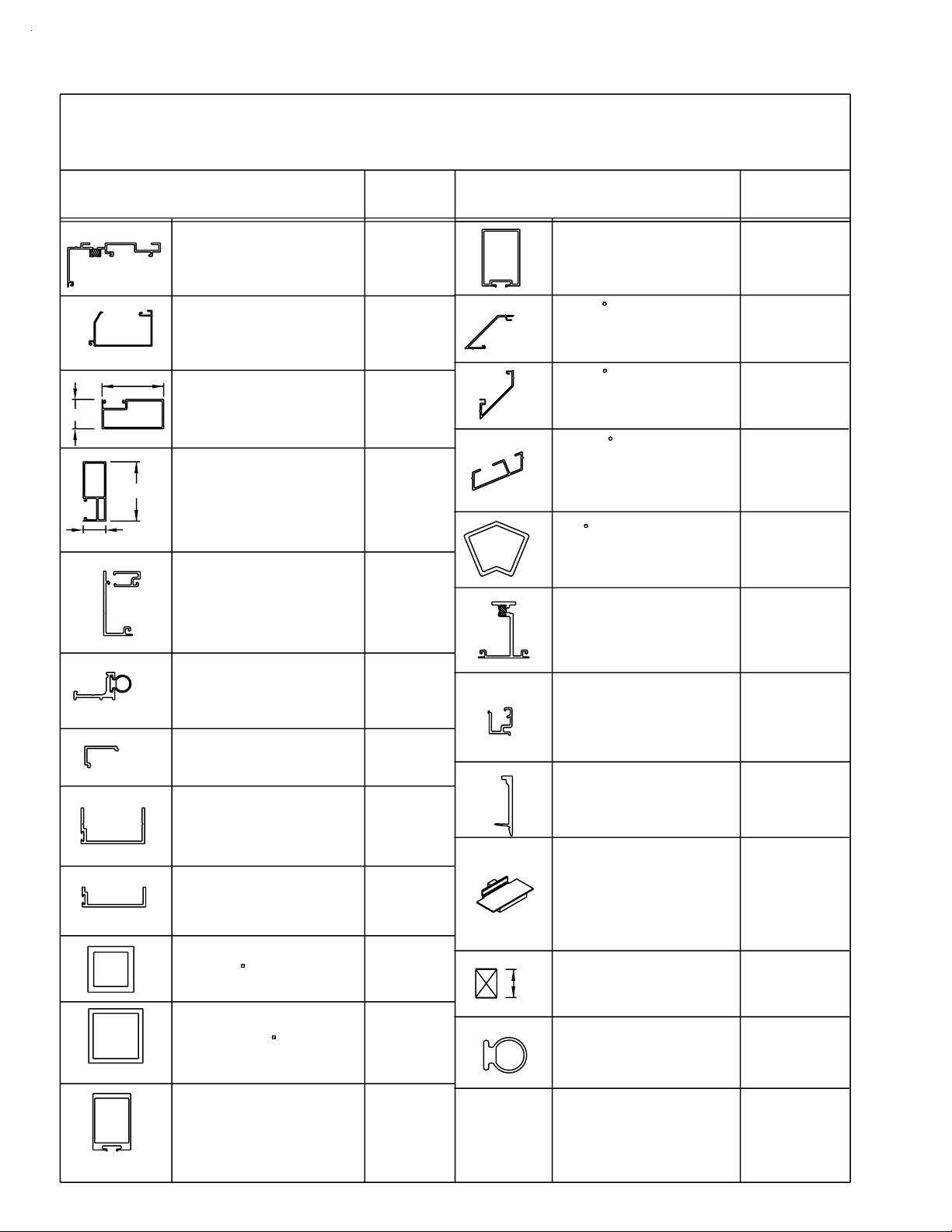
Page 4

PAGE 2
SECTION II A -
4 1/2" NONTHERMAL FRAMING
DESCRIPTION
HEAD AND SILL
4 1/2" CAN
USE 9485 CAN FILLER
CAN FILLER
USE w/ 9479
INTERMEDIATE
HORIZONTAL
USE 9587 & 9565
INTERMEDIATE
HORIZONTAL FACE
USE w/ 9469
PARTS IDENTIFICATION CHART
SERIES 901 QUICK SET
1/4" GLAZING
PART NO.
9479
9485
9469
9565
DESCRIPTION
BUTT GLAZED
VERTICAL MULLION
90 CORNER
MULLION HALF
MATES w/ 7256
90 CORNER
MULLION HALF
MATES w/ 7255
135 CORNER
MULLION HALF
2 REQUIRED
PART NO.
7253
7255
7256
7260
INTERMEDIATE
HORIZONTAL STOP
USE w/ 9469
CAPTURED MULLION/
JAMB BACK
8593 2 pc. JAMB
9579 VERT. FACE
CAPTURED
VERT. MULLION
FACE
USE w/ 9578
CAPTURED VERT.
MULLION STOP
2 REQUIRED w/ 9578 - 9579
CAPTURED
2 PC JAMB
SLIDE on FACE
USE w/ 9578
2 PC. JAMB
GLAZING STOP
USE w/ 8593
2 COLOR COVER
USE w/ 9479
HEAD/SILL CAN
9587
9578
9579
9580
8593
8589
9571
4 1/2"
2 1/2"
2"
4 1/2"
TRANSOM HEAD
1/4" GLAZING
USE 7861 STOP
TRANSOM HEAD
GLAZING STOP
1/4" GLAZING
2" DOOR JAMB or
DOOR HEADER W/
SURFACE CLOSER
USE w/ 9154/9155 STOP
2 1/2" DOOR HEADER
for C.O.C.
USE 9914 STOP/COVER
OR 9933 STOP/COVER
APPLIED DOOR STOP
USE w/ 9155. USE W138
WEATHER STRIP
ATTACH w/ STT6 SCREW
APPLIED DOOR STOP
COVER
USE w/ 9154
DOOR STOP FOR C.O.C.
DOOR HEADER
USE w/ DORMA RTS 88 C.O.C.
OR INTERNATIONAL C.O.C.
DOOR STOP FOR C.O.C.
DOOR HEADER
USE w/ LCN 2030 C.O.C.
9472
7861
9597
9598
9154
9155
9914
9933
HEAVY-DUTY
BUTT GLAZED
VERTICAL MULLION
7028
DPS 7/2001
Page 5

PAGE 3
SECTION II A - PARTS IDENTIFICATION CHART
SERIES 901 QUICK SET 4 1/2" NONTH ERMAL FRAMING
1/4" GLAZING
DESCRIPTION PART NO. DESCRIPTION PART NO.
EX32
9470
F076
F077
FS67
FT14
INTERMEDIATE
HORIZONTAL SH EAR
BLOCK USE
w/ 9469 (1) F365, (3) MRF8, (1) S110
2 1/2" C.O.C. DOOR
HEADER SHEAR BLOCK
901 - 9598
(2) STV2, (1) F076/(1) F077
(2) S117/(2) STD8
2" DOOR JAMB as DOOR
HEADER SHEAR BLOCK
901 - 9597
(1) FS67, (2) STV2, (2) MRF1/(2)
MRF6
TRANSOM HEADER SHE AR
BLOCK PACKAGE USE w/
9472
(1)F259,(1)F260,(6)STT6,(4)MRF6
HEAD/SILL CAN ANCHOR
CLIP (USE w/ 9578 at
JAMBS)
(1) FT14, (4) SFP8
HORIZONTAL BRIDGE
ASSEMBLY 1/4" GLAZING
at BUTT GLAZE
MULLIONS ONLY w/ INT.
HORIZ.
(1) F023, (1) H189, (1) WM76
K176
K309/K311
(CLR. - R / L )
K310/K312
(BRZ. - R / L)
K278
(CLR.)
K279
(BRZ.)
K277
K433
K143
SHEAR BLOCK PKG. F OR
#8583 HORIZ. at 135°
S.S.G. OUTSIDE CORNER
(1) FT92, (1) FT93, (2) MTZ4, (4) SPC9,
(1) S110
SHEAR BLOCK PKG. F OR
#8583 HORIZ. at 135°
S.S.G. INSIDE CORNER
(1) FT94, (1) FT95, (4) MTZ4, (2) SPC9,
(1) S110
1/4" SETTING BLOCK A T
SILL CAN
WEEP BAFFLES
25 PER PKG.
INTERMEDIATE
HORIZONTAL SETTING
BLOCK US E w/ 9469
BUTT GLAZED SPACER
3/8" x 1/2" TAPE USE w/
7028 & 7253
TEMPORARY GLAZING
CLIP USE w/ 7028 & 7253
K490
K491
HNA1
HCW6
HEP2
WM10
HV11
7885
FT98
FT99
Q-SET
INTERMEDIATE
HORIZONTAL FACE SPLICE
USE w/ 9565 FACE
(1) F024, (1) F025
HEAD/SILL SPLICE for 901
(USE w/ 9479)
25 PER PACKAGE (1) F014, (1) WM96,
(1) WM01
SHEAR BLOCK PKG. F OR
#8583 HORIZ. @ 90° S.S.G.
INSIDE/OUTSIDE CORNER
(1) FT98, (1) FT99, (4) STV2, (4) ST K4
K146
K376
K493
HORIZONTAL END DAM
at 2 PC JAMB INSTALLS
IN GLAZING POCKET IN
HEAD & SILL CAN
GLAZING GASKET
500' PER ROLL
STANDARD WEATHER
SEAL @ DOOR STOPS
HN30
W164
W138
CDB 9/2009
Page 6

PAGE 4
SECTION II B -
DESCRIPTION
HEAD and SILL
5 1/4" CAN
USE 9485 CAN FILLER
CAN FILLER
USE w/ 9484, 9845 OR 1G66
THERMAL STRUT
HEAD and SILL
5 1/4" CAN
USE 9485 CAN FILLER
OUTSIDE GLAZED
HEAD/SILL CAN
USE 9485 CAN FILLER
9846 or 9847 FACE
OUTSIDE GLAZED
SILL CA N FA CE
USE w/ 9845
OUTSIDE GLAZED
HEAD C A N FACE
USE w/ 9845
INTERMEDIATE
HORIZONTAL
USE w/ 8499, 8584, 9541
INTERMEDIATE
HORIZONTAL FACE
USE w/ 8583 or 8500
INTERMEDIATE
HORIZONTAL
GLAZING STOP
USE w/ 8583
OPT. H.D. HORIZONTAL
INTERMEDIATE
USE K176 S.B.
8499 FACE & 9587 STO P
H.D. INTERMEDIATE
HORIZONTAL
GLAZING STOP
USE w/ 8500
OPT. INTERMEDIATE
HORIZONTAL
GLAZING STOP
1/4" GLASS W/ 8583/8500
PARTS IDENTIFICATION CHART
SERIES 902 QUICK SET
5 1/4" THERMAL FRAMING
1" GLAZING
PART NO.
9484
9485
1G66
9845
9846
9847
8583
8499
8584
8500
9587
9541
DESCRIPTION
CAPTURED
MULLION BACK
USE w/ 9576 & 8594
CAPTURED MULLION
SLIDE ON FACE
USE w/ 9578
CAPTURED
MULLION STOP
2 REQUIRED w/
9578 & 1G41
2 PC JAMB
SLIDE on FACE
USE w/ 9578
& 8589
2 PC JAMB
GLASS STOP
USE w/
9578 & 8594
CAPTURED VERTICAL
'I' BAR (2) COLOR
USE WITH
(2) 9580 STOPS
OPTIONAL
CAPTURED VERTICAL
MULLION & JAMB STOP
for 1/4" GLASS
USE w/
9578 & 1G41
1/2" GLAZING ADPT.
at 1" GLAZING PO CK ETS
1/4" GLAZING ADPT.
at 1" GLAZING PO CK ETS
2 COLOR COVER
(9484 HEAD/SILL CAN)
PART NO.
9578
9576
9580
8594
8589
1G41
9542
9260
9261
9570
BAH 4/2005
Page 7
PAGE 5
SECTION II B -
DESCRIPTION
TRANSOM HEAD
USE w/ 7861
& K267 CLIP
TRANSOM HEAD
GLAZING STOP
1" GLAZING
5 1/4"
2 1/2"
5 1/4"
2"
APPLIED DOOR STOP
USE W138 WEATHERING
ATTACH w/ STT6 SCREW
APPLIED DOOR STOP
C.O.C. DOOR HEADER
C.O.C. DOOR HEADER
USE w/ (1) 7255 &(1) 7256
For C.O.C.
DOOR HEADER
2 1/2"
SURFACE CLOSER
DOOR HEADER w/
2" DOOR JAMB
TRANSOM JAMB
APPLIED GLAZING
1" SIGHT LINE
(USE w/ 9592)
USE w/ 9155
COVER
USE w/ 9154
DOOR STOP FOR
USE w/ DORMA RTS 88
OR INTERNATIONAL
DOOR STOP FOR
USE w/ LCN 2030 C.O.C.
1" x 1" x 1/8" TUBE
@ 90 CORNER
PARTS IDENTIFICATION CHART
SERIES 902 QUICK SET
5 1/4" THERMAL FRAMING
1" GLAZING
PART NO.
9539
7861
9593
9592
9133
9295
9154
9155
9914
9933
EY54
DESCRIPTION
BUTT GLAZED
VERTICAL MULLION
90 CORNER
MULLION HALF
(MATES w/ 7256)
90 CORNER
MULLION HALF
(MATES w/ 7255)
135 CORNER
MULLION HALF
(2 REQUIRED
SELF-MATING)
45 BUTT GLAZED
CORNER ADAPTOR
USE w/ (2) 7260
BUTT GLAZED ADAPT.
USE w/ 7028 or 7253
for BUTT GLAZE ABOVE
CAPTURED BELOW
1/4" GLAZING ADPT.
USE at BUTT
GLAZED MULLS
USE w/ 7253 or 7028
TEMPORARY
GLAZING CLIP
for 7028 or 7253
25 PER PKG.
HORIZONTAL
BRIDGE ASSEMBLY
1" GLAZING at BUTT
GLAZE MULLIONS ONLY
w/ INT. HORIZ.
USE w/ 9558 & 9559
BUTT GLAZED SPACER
1/2"
3/8 x 1/2 TAPE USED
w/ 7028 & 7253
CONT.
PART NO.
7253
7255
7256
7260
9258
9471
9574
HV10
K142
WM10
Q-SET
1 1/2" x 1 1/2" x 1/8"
TUBE @ 90 CORNER
USE w/ (2) 7253 OR 7028
HEAVY-DUTY
BUTT GLAZED
VERTICAL MULLION
EX85
7028
STANDARD
WEATHER SEAL
@ DOOR STOPS
W138
DPS 12/2002
Page 8

PAGE 6
SECTION II B - PARTS IDENTIFICATION CHART
SERIES 902 QUICK SET 5 1/4" THERMAL FRAMING
1" GLAZING
EX32
FT14
DESCRIPTION
INTERMEDIATE HORIZONTAL
SHEAR BLOCK USE w/ 8583
or 8500
(1) F365, (3) MRF8, (1) S110
HEAD/SILL CAN ANCHOR
CLIP USE w/ 9578 at JAMBS
(1) FT14, (4) SFP8
TRANSOM HEADER SHEAR
BLOCK PACKAGE USE w/ 9539
(1) F344, (1) F345, (8) STT6, (4) MRF6
2" DOOR JAMB as DOOR
HEADER SHEAR BLOCK 902
- 9592
FS67
FT98
FT99
(1) FS67, (2) STV2, (2) MRF1/(2) MRF6
F078
2 1/2" - C.O.C. DOOR HEADER
F079
SHEAR BLOCK 902 - 9593
(1) F078, (1) F079, (4) STV2, (4) S117/(4)
STD8
SHEAR BLOCK PKG. FOR
#8583 HORIZ. at 135°
S.S.G. OUTSIDE CORNER
(1) FT92, (1) FT93, (2) MTZ4, (4) SPC9,
(1) S110
SHEAR BLOCK PKG. FOR
#8583 HORIZ. at 135°
S.S.G. INSIDE CORNER
(1) FT94, (1) FT95, (4) MTZ4, (2) SPC9,
(1) S110
SHEAR BLOCK PKG. FOR
#8583 HORIZ. @ 90° S.S.G.
INSIDE/OUTSIDE CORNER
(1) FT98, (1) FT99, (4) STV2, (4) STK4
1" SETTING BLOCK for
INTERMEDIATE HORIZONTAL
PART NO.
K176
K433
K267
K278
(CLR.)
K279
(BRZ.)
K273
(CLR.)
K274
(BRZ.)
K490
K491
K493
HN90
DESCRIPTION
HEAD/SILL CAN SPLICE
(USE WITH 9484)
25 PER PACKAGE (1) F015, (1) WM96,
(1) WM01
HEAD/SILL CAN SPLICE
(USE WITH 1G66)
(1) FU12, (1) WM96
OUTSIDE GLAZED
HEAD/SILL SPLICE (USE
WITH 9845)
(1) F001, (1) WM96
WEEP BAFFLES
INTERMEDIATE
HORIZONTAL FACE
SPLICE USE w/ 8499
(2) FT49
WATER DEFLECTOR @ INT.
HORIZONTAL
GLAZING GASKET
500' PER ROLL
1" SETTING BLOCK at
1G66 SILL CAN
25 PER PACKAGE
SETTING BLOCK for 9592
JAMB when used as
TRANSOM
PART NO.
K377
K917
K375
HCW6
K460
HWD1
W164
FU08
HN32
HORIZONTAL END DAM for
1" GLZ. @ 2 PC. JAMB
1" SETTING BLOCK at SILL
CAN
25 PER PACKAGE
HN31
HN33
CDB 9/2009
Page 9

PAGE 7
SECTION II C -
SERIES 903 QUICK SET
3 1/4" NONTHERMAL FRAMING
DESCRIPTION
HEAD and SILL
3 1/4" CAN
USE 9478 FILLER
CAN FILLER
USE w/ 9476
INTERMEDIATE
HORIZONTAL
USE W/ 9565 & 9566
INTERMEDIATE
HORIZONTAL STOP
USE W/ 9586
INTERMEDIATE
HORIZONTAL FACE
USE w/ 9586
PARTS IDENTIFICATION CHART
1/4" GLAZING
PART NO.
9476
9478
9586
9566
9565
DESCRIPTION
BUTT GLAZED
VERTICAL MULLION
HEAVY-DUTY
BUTT GLAZED
VERTICAL MULLION
90 CORNER
MULLION HALF
(2 REQUIRED)
135 CORNER
MULLION HALF
(2 REQUIRED)
PART NO.
9558
9559
9563
9562
CAPTURED VERTICAL
MULLION / JAMB
BACK
9579 VERT. FACE
8593 2 pc. JAMB FACE
CAPTURED
MULLION FACE
USE W/ 9575
CAPTURED
MULLION STOP
USE (2) w/ 9575 & 9579
2 PC JAMB
SLIDE on FACE
USE W/ 9575
2 PC JAMB
GLASS STOP
USE w/ 9575 & 8593
2 COLOR COVER
at HEAD and SILL CAN
USE w/ 9476
9575
9579
9577
8593
8590
9572
DPS 7/2001
Page 10

PAGE 8
SECTION II C - PARTS IDENTIFI CATION CHART
SERIES 903 QUICK SET 3 1/4" NONTHERMAL FRAMING
1/4" GLAZING
CONT.
FT15
7885
DESCRIPTION PART NO. PART NO.
INTERMEDIATE HORIZONTAL
SHEAR BLOCK USE w/ 958
(1) F021, (3) MRF7
HEAD/SILL CAN ANCHOR
CLIP USE w/ 9575 at JAMB
(1) FT15, (4) SFP8
HEAD/SILL CAN SPLICE
USE w/ 9476
25 PER PACKAGE
INTERMEDIATE
HORIZONTAL FA CE
SPLICE USE w/ 9565 FACE
(1) F024, (1) F025
HORIZONTAL BRIDGE
ASSEMBLY 1/4" GLAZING at
BUTT GLAZE MULLIONS ONLY
w/ INT. HORIZ. USE w/ 9558
and 9559
(1) F023, (1) H189, (1) WM76
ANCHOR CLIP @ PERIMETER
JAMBS
(1) FT15, (4) SFP8
K141
K434
K378
K146
K143
K434
DESCRIPTION
1/4" SETTING BLOCK
USE w/ 9476
HORIZONTAL END DAM
for 1/4" GLZ. at 2 PC.
JAMB INSTALLS in
GLAZING POCKET in HEAD
and SILL CAN
WEEP BAFFLES
25 PER PKG.
GLAZING GASKET
500' PER ROLL
INTERMEDIATE
HORIZONTAL SETTING
BLOCK USE w/ 9586
BUTT GLAZED SPACER 3/8"
x 1/2" TAPE USE w/ 9558
and 9559
TEMPORARY GLAZING
CLIP USE w/ 9558 and
9559
HNA2
HN30
HCW6
W164
H191
WM10
HV11
CDB 9/2009
Page 11

PAGE 9
SECTION II D -
SERIES 904 QUICK SET
4" THERMAL FRAMING
DESCRIPTION
HEAD and SILL CAN
FLAT BOTTOM
USE 9478 CAN FILLER
HEAD and SILL CAN
CONCEALED WEEP
USE 9478 CAN FILLER
CAN FILLER
USE w/ 9477 & 9468
OUTSIDE GLAZED
HEAD / SILL CAN
USE 9478 CAN FILLER
PARTS IDENTIFICATION CHART
1" GLAZING
PART NO.
9477
9468
9478
8716
DESCRIPTION
2 PC JAMB
SLIDE on FACE
(USE w/ 9575)
2 PC JAMB
GLASS STOP
USE w/ 9575
HEAVY-DUTY
BUTT GLAZED
VERTICAL MULLION
BUTT GLAZED
VERTICAL MULLION
PART NO.
8594
8590
9559
9558
OUTSIDE GLAZED
SILL CAN
USE w/ 8716 CAN
OUTSIDE GLAZED
HEAD CAN
USE w/ 8716 CAN
INTERMEDIATE
HORIZONTAL
USE w/ 9565 & 9566
INTERMEDIATE
HORIZONTAL STOP
USE w/ 9564
INTERMEDIATE
HORIZONTAL FACE
USE w/ 9564
CAPTURED VERT.
MULLION / JAMB
BACK
9576 VERT. FACE
8594 2 pc. JAMB FACE
CAPTURED VERT.
MULLION FACE
USE w/ 9575
CAPTURED VERT.
MULLION STOP
USE (2) w/ 9575
9846
9847
9564
9566
9565
9575
9576
9577
90 CORNER
MULLION HALF
(2 REQUIRED)
135 CORNER
MULLION HALF
(2 REQUIRED)
1" x 1" x 1/8" TUBE
@ 90 CORNER
USE w/ (2) 9563
at 90 CORNER
45 BUTT GLAZED
CORNER ADAPTOR
USE w/ (2) 9562
1 1/2"x1 1/2"x1/8"
TUBE @ 90 CORNER
USE w/ (2) 9558 or 9559
BUTT GLAZED
ADAPTOR
USE w/ 9558 or 9559
for BUTT GLAZED ABOVE
CAPTURED BELOW
1/2" GLAZING ADPT.
at 1" GLAZING POCKETS
1/4" GLAZING ADPT.
at 1" GLAZING POCKETS
9563
9562
EY54
9258
EX85
9471
9260
9261
DPS 7/2001
Page 12

PAGE 10
9
SECTION II D - PARTS IDENTIFICATION CHART
SERIES 904 QUICK SET 4" THERMAL
FRAMING 1" GLAZING
CONT.
PART NO.DESCRIPTIONPAR T NO.DESCRIPTION
INTERMEDIATE HORIZONTAL
SHEAR BLOCK USE w/ 9564
(1) F021, (3) MRF7
1/4" GLAZING ADPT. at
BUTT GLAZED MUL L USE w/
9558 or 9559
OUTSIDE GLAZED HEAD/SILL
SPLICE USE w/ 8716 O.G.
CAN
(1) F001, (1) WM96
HEAD/SILL CAN SPLICE USE
w/ 9477 & 9468 25 PER
PACKAGE
(1) F017, (1) WM96, (1) WM01
HORIZONTAL BRIDGE
ASSEMBLY 1" GLAZING at
BUTT GLAZE MULLIONS
ONLY w/ INT. HORIZ. USE w/
(1) F022, (1) H189, (1) WM76
9564
K141
9574
K375
K379
K142
WATER DEFLECTOR @
INT. HORIZONTAL
1" SETTING BLOCK at
SILL CAN
GLAZING GASKET
500' PER ROLL
BUTT GLAZED SPACER
3/8" x 1/2" TAPE USE w/
1/2"
TEMPORARY GLAZING
CLIP for 7028 or 7253
25 PER PKG.
7028 & 7253
HWD1
HN34
W164
WM10
HV10
INTERMEDIATE HORIZONTAL
FACE SPLICE USE w/ 9565
(1) F024, (1) F025
FACE
ANCHOR CLIP @ PERIMETER
JAMBS
(1) FT15, (4) SFP8
HORIZONTAL END DAM for 1"
GLZ. at 2 PC. JAMB INSTALLS
in GLAZING POCKET in HEAD
and SILL CAN
WEEP BAFFLES
25 PER PKG.
1" SETTING BLOCK for
INTERMEDIATE
HORIZONTAL
K146
K434
HN31
HCW6
HN90
CDB 9/200
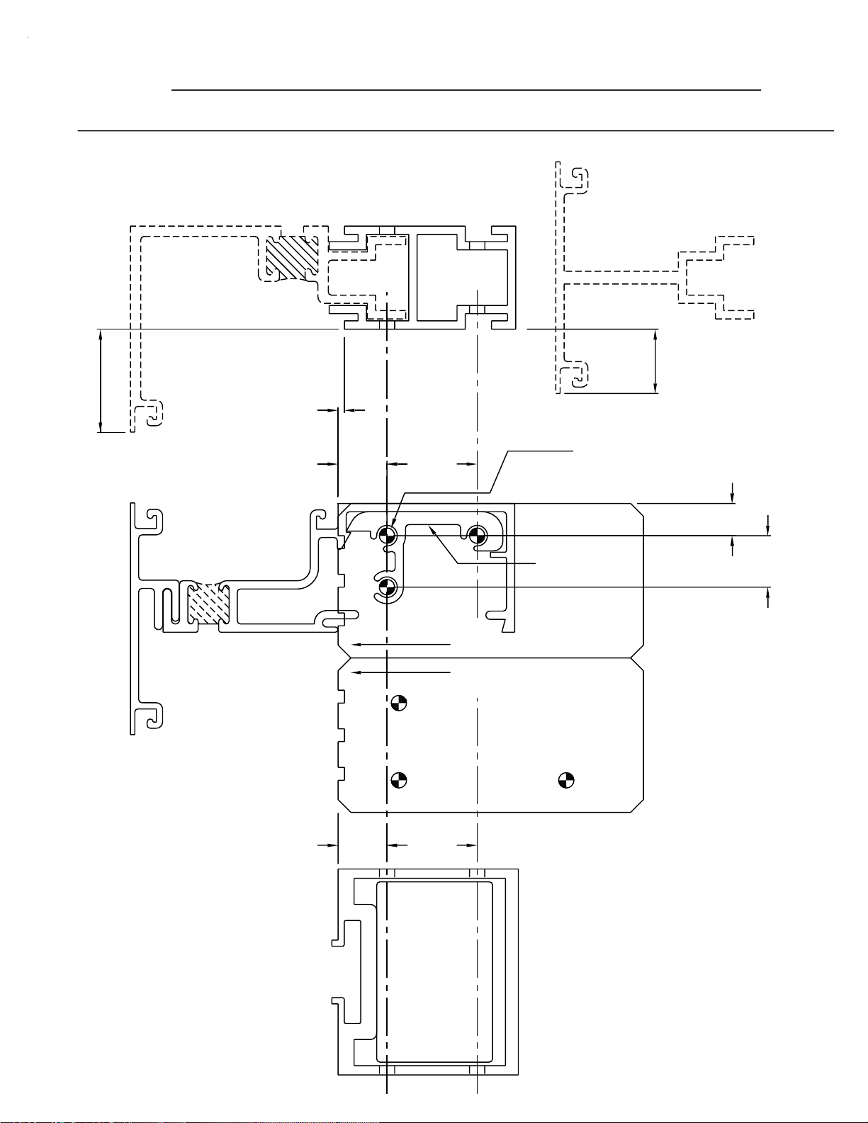
Page 13

PAGE 11
SECTION III A - FABRICATION
DRILLING TEMPLATE - 901/902 INTERMEDIATE HORIZONTAL
2 PC. CAPTURED
JAMBS
VERTICALS
1.000
5/8" NOTCH
AT VERTICALS
AT JAMB
1" NOTCH
8594
OR 8593
NOTE: OFFSET
.062
#10-24x
1/2" F.H.
(S110)
8583
.590
9578
TOP OF
HORIZONTAL
1.625
901/902 SYSTEMS
FRONT OF MULLION
9576
OR 9579
.625
.149 DIA. (#25 DRILL)
FOR #10-24 x 1 3/4" P.H.S.M.S.
(3) MRF8
.312
.750
K176
FRONT OF MULLION
903/904 SYSTEMS
(9470)
8499
.590
HORIZONTAL
TOP OF
1.625
BUTT GLAZED
VERTICALS
7028
7253
JDA 10/2001
Page 14
PAGE 12
SECTION III B - FABRICATION
DRILLING TEMPLATE - 903/904 INTERMEDIATE HORIZONTAL
1.000
8594
OR 8593
NOTE: OFFSET
9586/9564
2 PC. JAMB
.062
.475
9575
.875
TOP OF
HORIZONTAL
K141
(9567)
CAPTURED
9579
OR 9576
.149 DIA. (#25 DRILL)
FOR #10-24 x 1 3/4" P.H.S.M.S.
(3) MRF8
VERTICALS
.625
.313
.500
9565
.475
903/904 SYSTEMS
FRONT OF MULLION
.875
9559
FRONT OF MULLION
901/902 SYSTEMS
HORIZONTAL
TOP OF
BUTT GLAZED
VERTICALS
9558
JDA 10/2001
Page 15

SECTION III C - FABRICATION
HEAD AND SILL CAN
INCLUDES CAPTURED AND BUTT
GLAZED MULLION SYSTEMS
STEP 1)
Measure the opening to determine the cut length of the head
and sill frame components. Allow for shims if applicable.
STEP 2)
Cut head and sill cans to frame width. This includes any
"2" color covers that are being used.
NOTE: Expansion/splice joints are required in elevations that exceed
20’-0" in width. Plan for expansion/splice joints to fall at
the center of the nearest lite and adjust cut lengths accordingly.
PAGE 13
1/4"
OPT.
SHIM
JAMB
HEAD & SILL LENGTH
20 FT. MAXIMUM
20 FT. TYPICAL
[FIG. 1]
1/2"
1/4"
OPT.
SHIM
JAMB
EXPANSION/SPLICE
JOINT
STEP 3)
Drill 1/4" weep holes in sill can 6" from jambs and 48" on
center or if the length is less than 48", drill (1) per lite. This
includes 2 color covers, installed prior to weeping and anchoring.
See Fig. 3 on Page 14.
NOTE: Sill cans with riser legs are bottom weeped and sill cans with flat
bottoms are face weeped.
HCW6
HOLE IN BOTTOM
901/902
[FIG. 2]
HCW6
903/904
HOLE IN FACE
DPS 7/2001
Page 16

SECTION III C - FABRICATION
PAGE 14
HEAD AND SILL CAN
INCLUDES CAPTURED AND BUTT
GLAZED MULLION SYSTEMS
TAP LIGHTLY
TO SNAP IN PLACE
HOOK COVER OVER LEG
CRIMP THIS LEG SLIGHTLY TO
DRILL 1/4" DIA. WEEP HOLES
THRU COVER AND SILL
OPTIONAL SEAL
(LEAVE 1/4" SPACE
AT WEEP HOLES)
LOCATE PRIMARY SEAL
BEHIND COVER LEG.
[FIG. 3]
STEP 4) 90 AND 135 CORNER FABRICATION
PREVENT COVER FROM WALKING
OUT OF POSITION WITH THERMAL
EXPANSION.
(CONT.)
Head and sill cans are mitered for inside or outside corners.
This includes 2 color covers installed prior to anchoring.
See Fig. 4 below.
NOTE: An expansion/splice joint located 12" from the miter joint is
recommended to reduce expansion at the miter joint.
1/2"12"
90
FRAME DIM.
12"
1/2" 12"
1/2"
FRAME DIM.
12"
1/2"
FRAME DIM.
TOP VIEW OF THE SILL CAN AT
90˚ OUTSIDE AND 135˚ INSIDE CORNERS.
135
[FIG. 4]
DPS 7/2001
Page 17

SECTION III C - FABRICATION
PAGE 15
HEAD AND SILL CAN
STEP 5) Weep Baffle Installation
1/2 HCW6
SEALANT
BAFFLE
[FIG. 5]
(CONT.)
APPLY A SMALL AMOUNT OF SILICONE TYPE
SEALANT TO THE BAFFLES THAT WILL
STRADDLE THE DRILLED WEEP HOLE, AND
LOCATE THEM OVER THE WEEP HOLES AS
SHOWN. DO NOT PLUG THE WEEP HOLES
WITH SEALANT. CUT HCW6 IN HALF TO
CREATE CORRECT SIZE BAFFLES.
SEE FIG. 17 ON PAGE 23.
BAFFLE
WEEP HOLE
STEP 6) End Dam Installation
Install the dams in the ends of the head and sill flush with the end.
Tool sealant over the inside edges of the dam to insure a water seal.
The end dam must seal to the web of the jamb member (not shown).
See Fig. 6.
WEEP HOLE
SEALANT
[FIG. 6]
HN30 - 1/4" GLAZING POCKET [901 & 903]
HN31 - 1" GLAZING POCKET [902 & 904]
DPS 7/2001
Page 18
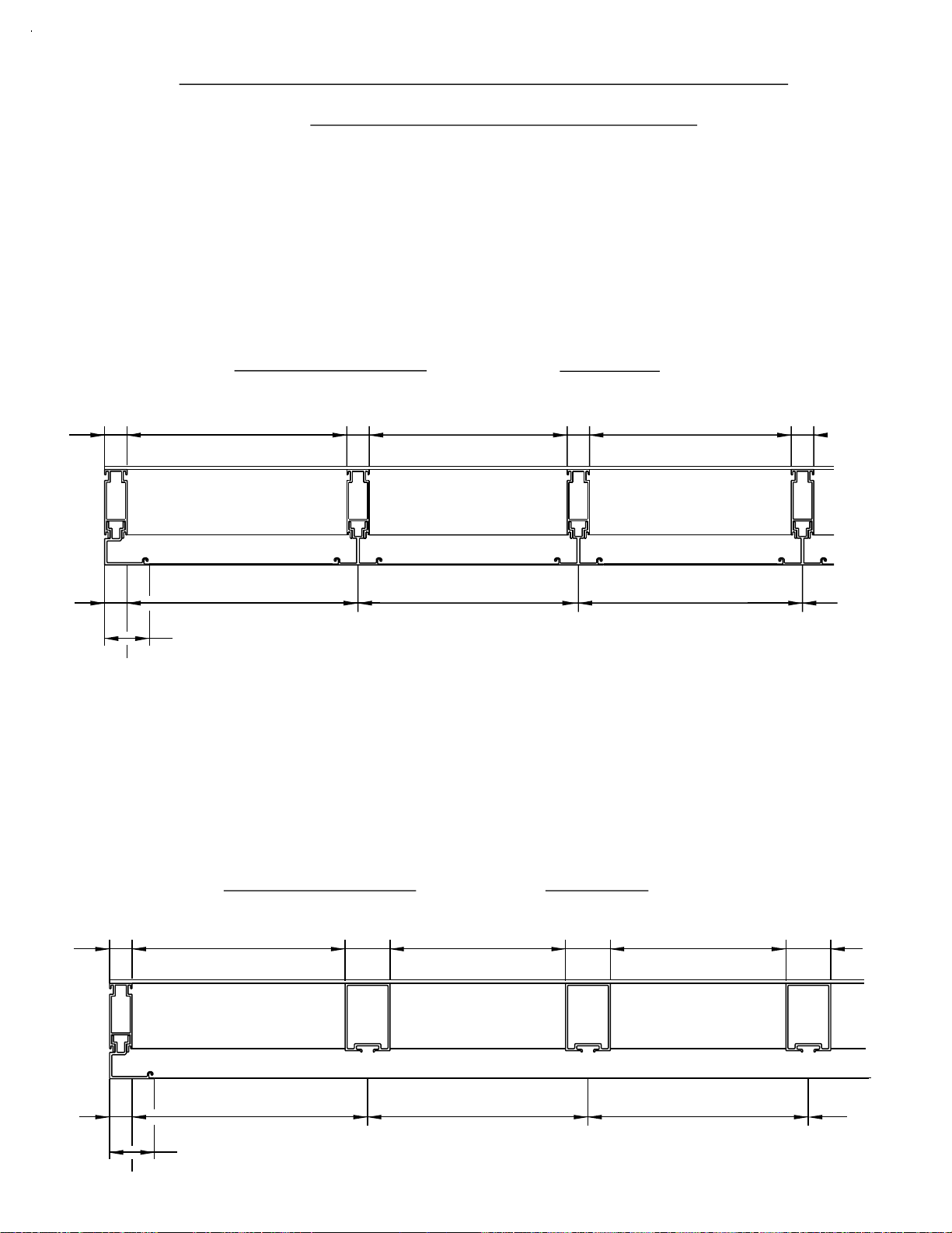
SECTION III D - FABRICATION
HEAD AND SILL CAN FILLER
PAGE 16
1) CAN FILLER CUT LENGTHS
Step 1) Determine center lines of each vertical mullion.
Step 2) Jamb to first mullion cut length = End of head/sill can
to center line of first mullion minus 1 1/2".
Step 3) Mullion to mullion cut length = Center line to center line
minus 1".
(Head and sill cans run through. Can fillers run mullion to mullion,
and mullion to jamb.)
CAN FILLER LENGTH
1"
1"
CAN FILLER
CUT LENGTH
MULLION
CENTER LINE
2"
1"
C
CENTER LINE
L
[FIG. 7]
C
L
(CAPTURED MULLION SYSTEMS)
1"
C
CAN FILLER LENGTH
MULLION MULLION
CENTER LINE
L
1"
C
L
2) CAN FILLER CUT LENGTHS
Step 1) Determine center lines of each vertical mullion.
Step 2) Jamb to first mullion cut length = End of head/sill can
to center line of first mullion minus 2".
Step 3) Mullion to mullion cut length = Center line to center line
minus 2".
(Head and sill cans run through. Can fillers run mullion to mullion,
and mullion to jamb.)
1"
1"
CAN FILLER
CUT LENGTH
MULLION
CENTER LINE
2"
CAN FILLER LENGTH
2"
MULLION
CENTER LINE
C
L
[FIG. 8]
C
L
(BUTT GLAZED SYSTEMS)
CAN FILLER LENGTH
2"
MULLION
CENTER LINE
C
L
2"
C
L
DPS 7/2001
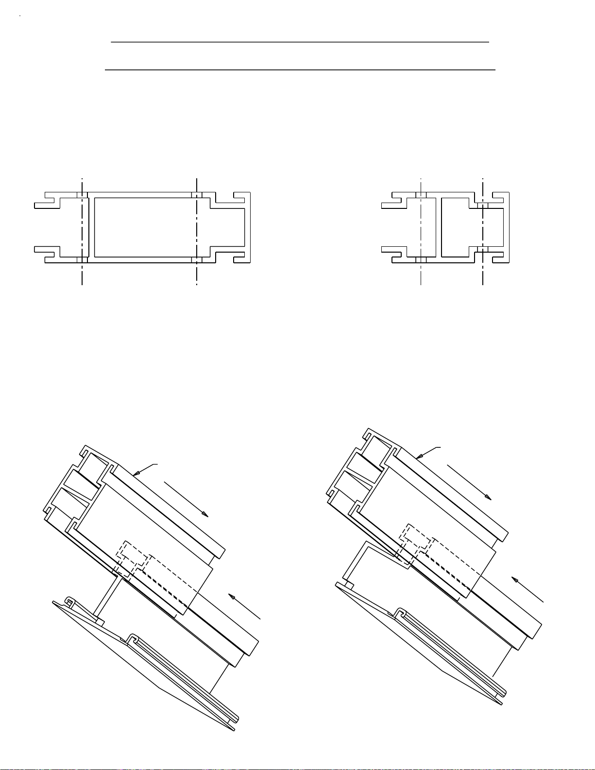
Page 19

SECTION III E - FABRICATION
*
VERTICAL INTERMEDIATE AND 2 PIECE JAMB
(BUTT GLAZED and CAPTURED MULLION SYSTEMS)
PAGE 17
STEP 1)
SERIES
901
902
Cut the captured mullion/jamb backs to the lengths shown in chart A
below. This will allow 1/8" clearance inside the head can.
Cut the butt glazed mullions to the lengths shown in chart A below.
This will allow 1/4" minimum clearance inside the head can.
Cut the captured mullion face and the 2 pc. jamb face to the D.L.O. height.
SYSTEM
DEPTH
HEAD/SILL
CAN #
9479
MULL #
9578
DESCRIPTION
CAPTURED VERTICAL
MULLION BACK
CUT LENGTHS
D.L.O. + 3 3/4"
4 1/2"
D.L.O. + 3 5/8"
D.L.O. + 4 1/4"
D.L.O. + 4 1/8"
D.L.O. + 3 11/16"
D.L.O. + 3 1/2"
D.L.O. + 3 1/4"
5 1/4"
9479
9484 or 9845
9484 or 9845
9484 or 9845
1G66
1G66
7253/7028
9578
7253/7028
1G41
NOTCHING REQ.
1G41
NOTCHING REQ.
7253/7028
BUTT GLAZED MULLIONS
CAPTURED VERTICAL
MULLION BACK
BUTT GLAZED MULLIONS
CAPTURED VERTICAL
I-BAR MULLION
CAPTURED VERTICAL
I-BAR MULLION
BUTT GLAZED MULLIONS
903
904
901/903
902/904
901/902
903/904
NOTE:
9476
9575
CAPTURED VERTICAL
MULLION BACK
D.L.O. + 3 1/4"
3 1/4"
D.L.O. + 3 1/8"
D.L.O. + 3 1/4"
D.L.O. + 3 1/8"
D.L.O. + 3 1/2"
D.L.O. + 3 3/8"
*
D.L.O.
D.L.O.
4"
4 1/2"-3 1/4"
5 1/4" - 4"
4 1/2"-5 1/4"
3 1/4" - 4"
9476
9477
9477
9468 or 8716
9468 or 8716
9558/9559
9575
9558/9559
9575
9558/9559
9579 & 8593
9576 & 8594
9580 & 8589
9577 & 8590
BUTT GLAZED MULLIONS
CAPTURED VERTICAL
MULLION BACK
BUTT GLAZED MULLIONS
CAPTURED VERTICAL
MULLION BACK
BUTT GLAZED MULLIONS
VERTICAL MULLION &
2 PC JAMB
FACE MEMBERS
GLASS STOPS
[CHART "A"]
HEAD AND SILL CANS, 9476, 9477, AND 1G66, DO NOT HAVE A RELIEF FOR
THE PERIMETER FASTENER HEAD. THEREFORE, AN ADDITIONAL
1/4" CLEARANCE +/- IS REQUIRED WHEN USING THESE CANS.
THIS CLEARANCE IS INCLUDED IN THE CUT LENGTH FORMULAS
IN CHART A.
Quick Set
If 2 color covers are used at the head and sill, the cut length of the vertical
*
mullion face member is D.L.O. minus 1/8".
JDA 4/2002
Page 20

SECTION III E - FABRICATION
PAGE 18
STEP 2)
VERTICAL INTERMEDIATE AND 2 PIECE JAMB
(BUTT GLAZED and CAPTURED MULLION SYSTEMS)
Notch the top of the mullion and jamb face 1/8" x 1/4" as shown in
Fig. 9 below. This prep is for ease of installation of the jamb and
vertical mullion.
8594
8593
(CONT.)
TOP OF MULLION FACE
9579 or 9576
1/4"
[FIG. 9]
1/8"
DPS 7/2001
Page 21
SECTION III E - FABRICATION
PAGE 19
STEP 3)
STEP 4)
VERTICAL INTERMEDIATE AND 2 PIECE JAMB
(BUTT GLAZED and CAPTURED MULLION SYSTEMS)
If horizontal intermediates are incorporated, drill for shear block
attachment screws using the drilling templates on pages 11 & 12.
Typical drilled members are shown in Fig. 10 below.
Jamb members will have preps on one side only.
9575
9578
[FIG. 10]
Cut length for the vertical mullion and jamb face is similar.
Please refer to chart ’A’ on page 17 and notching required
shown on page 18.
(CONT.)
STEP 5)
Slide the mullion face onto the mullion back as shown in Fig. 11.
See Section IV B for installation procedures.
JAMB BACK
MULLION BACK
MULLION
FACE
JAMB FACE
[FIG. 11]
DPS 7/2001
Page 22

SECTION III F - FABRICATION
t
INSULBAR INTERMEDIATE VERTICAL
PAGE 20
STEP 1)
STEP 2)
STEP 3)
Cut the thermal strut vertical mullion to the length shown in [CHART "A"]
on page 17 (SECTION III E - FABRICATION).
Notch the top of the mullion face 1/8" x 1/4" as shown in Fig. 12.
This prep is for ease of installation of the vertical mullion.
Notch the TOP of the mullion to leave the appropriate portion
as shown in Fig. 12 below.
The 2" dimension take n from the exterior face will be applicable
to all solid vertical intermediate mullions with 1" glazing.
COMPOSIT E #1G41 SHO WN
OTHER MULLIONS ARE SIMILAR
9546
9547
TOP OF MULLION FACE
1/8"
3/32"
2"
1/4"
3" (VARIES)
[FIG. 12]
1 17/32" @ #9484 & #9485 CAN
NOTCHING AT TOP OF MULLION
S902
{
1 5/8" @ 1G66 I-BAR CAN
S904
1 5/32" @ #9468 & #9477 CAN
{
1 1/2" @ #8716 CAN
Quick Se
BAH 4/2005
Page 23

SECTION III F - FABRICATION
Q
t
PAGE 21
STEP 4)
THERMAL STRUT INTERMEDIATE VERTICAL
Notch the BOT TOM of the mullion to leave the appropriate portion
as shown in Fig. 13 below.
The 2" dimension take n from the exterior face will be applicable
to all solid vertical intermediate mullion with 1" glazing.
COMPOSIT E #1G41 SHO WN
OTHER MULLIONS ARE SIMILAR
9546
9547
(CONT.)
BOTTOM OF MULLION FA CE
2 3/16" @ #9484 & #9485 CAN
2"
3" (VARIES)
[FIG. 13]
NOTCHING AT THE BOTTOM OF THE MULLION
uick Se
S902
{
1 29/32" @ 1G66 I-BAR CAN
BAH 4/2005
S904
{
2 3/16" @ #8716 CAN
1 25/32" @ #9468 & #9477 CAN
Page 24

PAGE 22
SECTION III G - FABRICATION
INTERMEDIATE HORIZONTAL
HORIZONTAL CUT LENGTH FORMULAS
CUT LENGTH = EXTERIOR D.L.O. + 1" {at 2 pc. JAMB to BUTT GLAZED MULLION
CUT LENGTH = EXTERIOR D.L.O. + 1 5/8" {at 2 pc. JAMB to
CAPTURED VERTICAL MULLION
CUT LENGTH = EXTERIOR D.L.O. + 1 1/4" {at CAPTURED VERTICAL MULLION to
CAPTURED VERTICAL MULLION
CUT LENGTH = EXTERIOR D.L.O. {at BUTT GLAZED MULLION to
BUTT GLAZED MULLION
THE FOLLOWING PREPS APPLY TO 902 AND 901 ONLY.
SYSTEMS 903 AND 904 HAVE A ’SNAP FIT’ TO THE SHEAR
BLOCK AND DO NOT REQUIRE DRILL/SCREW ATTACHMENT
OR NOTCHING.
NOTCH
5/8" LONG
AT VERTICALS
NOTCH
1" LONG
AT JAMB
1" x 7/32" NOTCH IS REQUIRED AT 2 PC. JAMBS ONLY.
5/8" x 7/32" NOTCH IS REQUIRED AT CAPTURED VERTICALS ONLY.
#10-24x
1/2" F.H.
(S110)
8583 SHOWN
9469 SIMILAR
PLEASE REFERENCE PAGE 35 FIG. 36.
[Fig. 14]
*
7/32"
[Fig. 15]
*
.344 (11/32") DRILL
BOTH ENDS
1"
5/8" NOTCH AT
CAPTURED VERTICALS
.542
8583
1" NOTCH AT
2 PC. JAMBS ONLY
DPS 7/2001
Page 25

SECTION III G - FABRICATION
PAGE 23
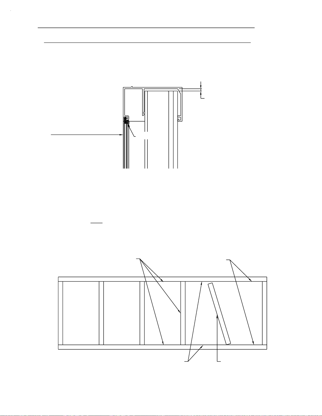
STEP 1)
NOTE:
INTERMEDIATE HORIZONTAL
(CONT.)
Cut horizontal face member to span 3 lites (or a maximum
of 15’-0"). Allow 1/4" at splice joints for expansion.
Splice ONLY at center lines of vertical mullions.
See Fig. 16 below.
D.L.O. 2"
INTERIOR
D.L.O.
D.L.O.2"
[FIG. 16]
HORIZONTAL FACE LENGTH (15 ft. max.)
Due to the expansion characteristics of the aluminum face member
and also to maintain the 1/4" splice joint, 15 feet is the
{
recommended cut length for the face member.
2"
D.L.O.
1/4"
STEP 2)
HCW6
5/8"
WEEP
HOLES
Weep baffles are cut from (1) HCW6, halved, to provide (2)
2" x 3/8" x 1/2" weep baffles. See Fig. 17 below.
1/2"
2"
2"
3/4"
[FIG. 17]
48" O.C.
3/8"
1/2"
9565 SHOWN
8499 SIMILAR
STEP 3)
APPLY BAFFLES WITH a SMALL
[FIG. 18]
AMOUNT of SILICONE TYPE SEALANT.
Drill 1/4" diameter weep holes in the horizontal face member at 48"
on center or 2 per lite at quarter points. Install weep baffles
over holes with silicone. Do not plug weep holes with silicone.
See Fig. 18 above.
DPS 7/2001
Page 26

SECTION III G - FABRICATION
PAGE 24
INTERMEDIATE HORIZONTAL
(Cont.)
CUT LENGTH FOR GLASS STOP = D.L.O. MINUS 1/32".
VERTICAL to VERTICAL - INTERIOR D.L.O.
CUT LENGTH FOR FACE MEMBER = 3 Lites - Not to exceed 15’
at BUTT GLAZE VERTICAL APPLICATIONS.
SYSTEM
& DEPTH
901 - 4 1/2"
902 - 5 1/4"
903 - 3 1/4"
904 - 4"
INTERM. HORIZ.
EXTRUSION NOS.
9469/9587/9565
8583/8584/8499
9586/9566/9565
9564/9566/9565
SHEAR BLOCK
REQUIRED
K-176
K-176
K-141
K-141
[CHART B]
STEP 4)
Figure the splice joint location to fall at the center line of a
vertical mullion, with respect to the 3 lite/15’ guideline.
SET SPLICE PLATES IN
SILICONE ONE END ONLY.
FILL VOID WITH SILICONE
CLEAN EXCESS FOR A
NEAT APPEARANCE
CENTER LINE OF VERTICAL MULLION
[FIG. 19]
EXPANSION JOINT
1/4"
DPS 7/2001
Page 27

SECTION IV A - INSTALLATION
HEAD AND SILL CAN ANCHORING
PAGE 25
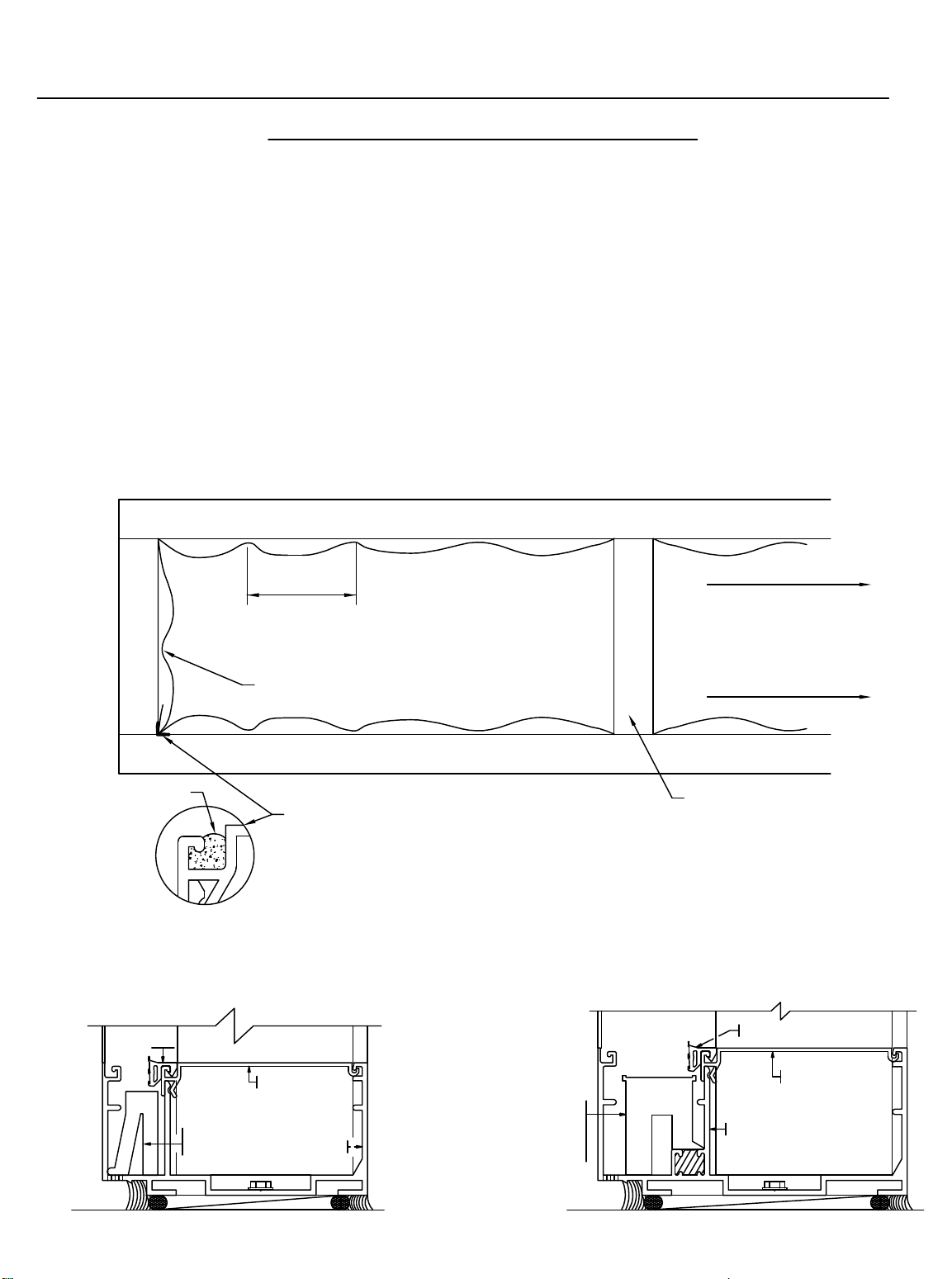
STEP 1)
END DAMS
Fasten head and sill cans to surround through back portion
of the can shape. Seal over all fastener heads in sill can.
See Fig. 20 below.
901/903 - HN30
END DAMS AT
JAMBS ONLY
SEALANT
902/904 - HN31
END DAMS
1/4" DIAMETER
MINIMUM FASTENERS
AT 3" EACH SIDE OF
VERTICAL MULLIONS
AND 24" MAXIMUM
ON CENTER.
(TYPICAL ALL SYSTEMS)
SHIMS ARE OPTIONAL WITH
THESE HEAD/SILL CANS
#9479 - S901
#9484 - S902
#9476 - S903
[FIG. 20]
#9468 - S904
DPS 7/2001
Page 28

SECTION IV A - INSTALLATION
HEAD AND SILL CAN SPLICE
PAGE 26
STEP 1)
[FIG. 21]
The main purpose of this operation is to ensure a water tight
seal between the two lengths of the sill can and prevent water from
entering the interior of the building. See Fig. 21 below.
SILL CAN
SPLICE SLEEVE
1" WIDE
BOND BREAKER
TAPE WRAPPED AROUND
THE SPLICE SLEEVE
AT THE CENTER.
SPLICE
JOINT
1/2"
STEP 2)
To ensure proper adhesion of sealant to all parts, clean the sill cans
at the splice area and the splice sleeve with "MEK" to remove all oils.
Slide the splice sleeve into the glazing pocket and center the sleeve
over the splice joint. See Fig. 22 below.
WM01 - 1" WIDE BOND
BREAKER TAPE WRAPPED
AROUND THE SPLICE SLEEVE
AT THE CENTER AND USED AS
A CAULK BACKER.
CAN # / SPLICE #
901 - 9479 / K376
902 - 9484 / K377
902 - 1G66 / K917
902 - 9845 / K375
903 - 9476 / K378
904 - 9477 / K379
904 - 9468 / K379
904 - 8716 / K375
SPLICE SLEEVE WITH
BOND BREAKER TAPE
CENTERED ON THE
SPLICE JOINT
[FIG. 22]
CLV 7/2001
Page 29

SECTION IV A - INSTALLATION
PAGE 27
STEP 3)
"A"
HEAD AND SILL CAN SPLICE
Apply a 1/4" bead of sealant over the ends of the splice sleeve.
Then tool the sealant across the edges of the sleeve and
onto the glazing pocket cavity surface. Be sure to work out any
air gaps that might occur. See Fig. 23 below.
APPLY SEALANT
ACROSS THE GAP TO
ADHERE TO THE SILL CAN
AND THE SPLICE SLEEVE.
WM01 - 1" WIDE BOND
BREAKER TAPE WRAPPED
AROUND THE SPLICE SLEEVE
AT THE CENTER AND USED AS
A CAULK BACKER.
(cont.)
TOOL SEALANT
TO ADHERE TO
BOTH SURFACES.
STEP 4)
STEP 5)
TOOL SEALANT
OVER ENDS
[FIG. 23]
"A"
CENTER VERTICAL
LEG OF SILL CAN
Apply sealant to the center vertical leg of the can, marrying
the seal to the splice sleeve and the two can members.
Proceed to the exterior face. Apply sealant to the exterior
splice joint gap, and tool sealant smooth.
BOND BREAKER TAPE
1.000
Quick Set
SECTION "A-A"
1/2"
SILL CAN
JDA 2/14/02
Page 30

SECTION IV B - INSTALLATION
2 pc. JAMBS AND INTERMEDIATE VERTICALS
PAGE 28
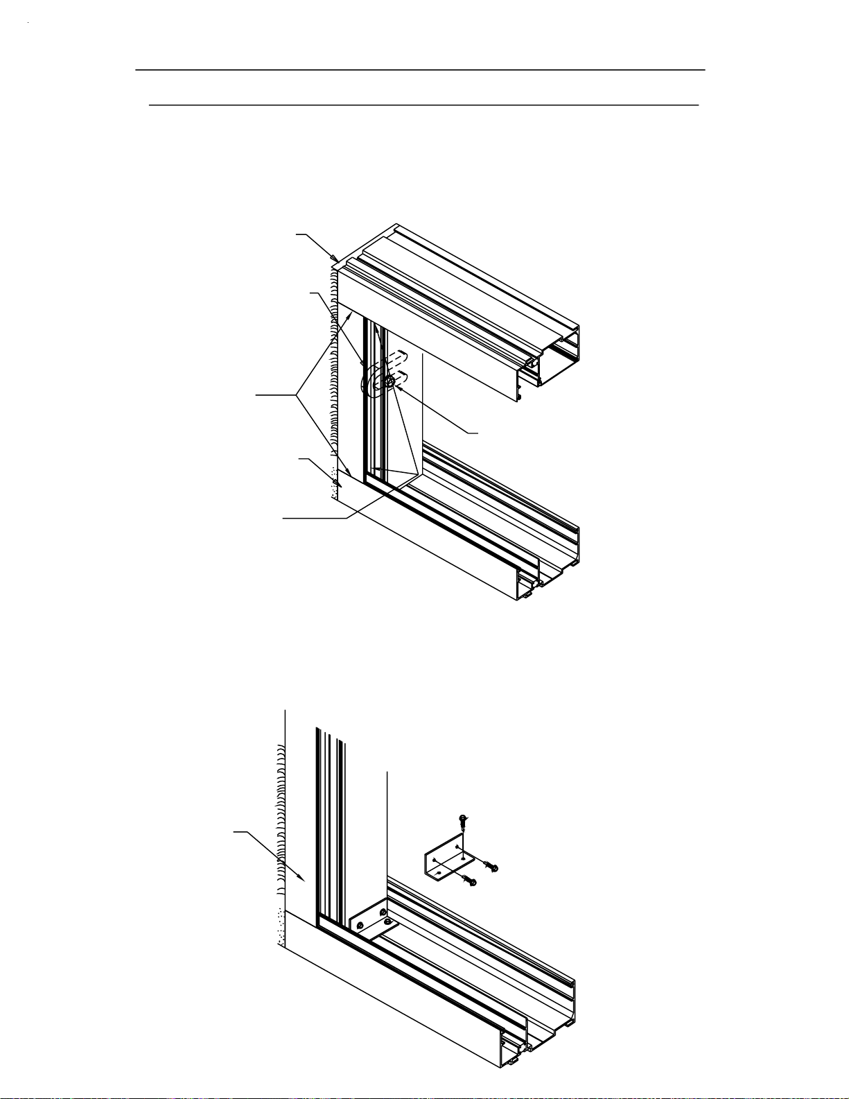
STEP 1)
Position the jamb assembly angled above the sill can at
the jamb location. Let the back portion of the jamb set
into the back portion of the sill can.
See Fig. 24 below.
Apply a butyl type sealant to
the glazing gasket receiver track
at the top and bottom
of the jamb location.
NOTE THAT THE
FACE PORTION IS
SHORTER THAN THE
BACK PORTION.
SWING UP
PERIMETER
STEP 2)
TAKE CARE NOT TO SCRATCH
THE FINISH ON THE HEAD CAN.
JAMB MEMBER
[FIG. 24]
While holding the assembly toward the exterior, swing the jamb
assembly up, letting the mullion back enter the back portion of
the head can. Using this procedure, the 1/8" notch in the face
portion of the vertical will allow clearance around the glazing
leg at the head.
HOLD JAMB OUT
UNTIL IT IS VERTICAL.
SEALANT IN GASKET
RECEIVER TRACK
See Fig. 25 below.
[FIG. 25]
THEN PUSH BACK
UNTIL THE FACE IS FLUSH
NOTCH IN THE VERTICAL
MULLION FACE
DPS 7/2001
Page 31
SECTION IV B - INSTALLATION
PAGE 29
2 pc. JAMBS AND INTERMEDIATE VERTICALS
NOTE:
AFTER THE JAMB IS IN PLACE,
APPLY A HEAVY COAT OF BUTYL
TYPE SEALANT AT THE HEAD AND
SILL GLAZING LEG AND ACROSS
THE TOP OF THE END DAMS.
The back member of the (2) pc. jamb and the intermediate vertical
will align the head and sill cans as it is installed.
END DAM
INSIDE
STANDARD HORSESHOE
SHIM, TYPICAL.
END DAM
INSIDE
(CONT.)
ATTACH THE 2 pc. JAMB
TO THE SURROUND
3" FROM TOP AND BOTTOM
AND 24" O.C. MAXIMUM.
AFTER THE JAMB IS IN PLACE,
SEAL ACROSS THE JOINT OF
THE JAMB-HEAD/SILL IN THE
GLAZING POCKET.
THIS STEP IS AT THE JAMBS ONLY.
2 pc. JAMB, TYP.
[FIG. 26]
2 pc. JAMB ANCHOR CLIP INSTALLATION
K433 for S901/S902
K434 for S903/S904
ANCHOR CLIPS ARE
REQUIRED AT THE
HEAD AND SILL CAN.
[FIG. 27]
ONLY AT PERIMETER
JAMBS.
DPS 7/2001
Page 32

SECTION IV B - INSTALLATION
PAGE 30
2 pc. JAMB AND INTERMEDIATE VERTICALS
STEP 3)
Apply a butyl type sealant to
the glazing gasket receiver track
at the top and bottom
of the vertical mullion location.
Position the vertical mullion assembly angled above the sill can at
approximately the vertical location. Let the back portion of the
vertical set into the back portion of the sill can.
See Fig. 28 below.
(CONT.)
NOTE THAT THE
FACE PORTION IS
SHORTER THAN THE
BACK PORTION.
STEP 4)
TAKE CARE NOT TO SCRATCH
THE FINISH ON THE HEAD CAN.
SWING UP
VERTICAL
INTERMEDIATE
[FIG. 28]
Swing the captured mullion assembly up, letting the mullion back enter
the back portion of the head can. The notch in the face portion
of the vertical will allow clearance around the glazing leg at the head.
See Fig. 29 below.
HOLD MULLION OUT
UNTIL IT IS VERTICAL.
SEALANT IN GASKET
RECEIVER TRACK
[FIG. 29]
NOTCH IN THE VERTICAL
MULLION FACE
DPS 7/2001
Page 33
SECTION IV B - INSTALLATION
PAGE 31
2pc. JAMBS AND INTERMEDIATE VERTICALS
STEP 5)
STEP 6)
After the vertical mullion is in position, let it move back
flush with the exterior face of the head and sill cans.
See Fig. 30 below.
CLEARANCE VARIES
SEE CHART ’A’ ON PAGE 17 FOR
MULLION CUT LENGTHS THAT
ESTABLISH THIS CLEARANCE.
MOVE BACK to FLUSH
FACES of MEMBERS
SEALANT
[FIG. 30]
Tap vertical mullion tight against the can fillers already in place.
Then repeat the installation of the next can fillers and vertical
mullions. Check every third mullion for correct spacing.
(CONT.)
NOTE:
MULLIONS INSTALLED TO HERE
[FIG. 31]
Install the last can filler of a run before the second to last.
This will allow tilting the last vertical mullion into place.
See Fig. 31 below.
CAN FILLERS AND VERT.
THESE CAN FILLERS ARE HELD OFF
UNTIL THE LAST VERTICAL IS INSTALLED
CAN FILLERS INSTALLED
TILT THE LAST VERTICAL INTO
POSITION AGAINST THE
CAN FILLERS
DPS 7/2001
Page 34

STEP 1)
The vertical butt glazed mullion is set into the rear portion of the HEAD/SILL
cans similar to the captured mullion. Then it is tapped against the can
fillers as before. Proceed to the next vertical.
See Fig. 32 below.
PAGE 32
SECTION IV C - INSTALLATION
BUTT GLAZED VERTICALS
CAN FILLER
INSTALLED
SILL CAN
VERTICAL BUTT
GLAZED MULLION
[FIG. 32]
DPS 7/2001
Page 35

SECTION IV C - INSTALLATION
PAGE 33
STEP 2)
#7256 MULL HALF MUST BE
INSTALLED BEFORE #7255
MULL HALF.
#7256
BUTT GLAZED VERTICALS
(cont.)
The butt glazed corners are (2) piece and require the first
half of the corner to be installed and then the other half.
Refer to the figures below to determine the related parts.
#7255
SILL CAN
for 90#7255
CORNER
(901 & 902)
NOTE:
Below are butt glazed corner mullion halves for each system
pertaining to available degree of corner combinations.
(2) 7260 FOR
135 CORNER
(901 & 902)
THIS HALF OF
MULLION IS SET
IN HEAD/SILL CAN
FIRST.
[FIG. 33]
APPLY DOUBLE
FACE TAPE
THIS HALF OF
MULLION IS SET
IN HEAD/SILL CAN
FIRST.
(2) 9563 FOR
90 CORNER
(903 & 904)
APPLY DOUBLE
(2) 9562 F0R
135 CORNER
(903 & 904)
FACE TAPE
THIS HALF OF
MULLION IS SET
IN HEAD/SILL CAN
FIRST.
[FIG. 34]
DPS 7/2001
Page 36

SECTION IV C - INSTALLATION
PAGE 34
STEP 3)
BUTT GLAZED VERTICALS
(cont.)
TYPICAL SHEAR BLOCK ATTACHMENT FOR S.S.G. CORNERS.
90 CORNER SHOWN BELOW IN FIG. 35, OTHERS SIMILAR.
ATTACH THE HORIZONTAL TO THE SHEAR BLOCKS WITH THE
FLAT HEAD SCREW SUPPLIED IN THE SHEAR BLOCK PACKAGE.
EDGE OF
MULLION
8583 HORIZ. SHOWN
OTHER HORIZ. TYP.
STK4
1.132"
2.117
K493
SHEAR BLOCK
PACKAGE
[FIG. 35]
STV2
7255/7256
S.S.G. CORNER
MULLION SHOWN
OTHERS SIMILAR
901/902 - 7255/7256 90 DEG. INSIDE OR OUTSIDE - K493
901/902 - 7260/7260 135 DEG. OUTSIDE - K490
3/4" TO TOP
OF HORIZONTAL
901/902 - 7260/7260 135 DEG. INSIDE - K491
DPS 7/2001
Page 37

SECTION IV D - INSTALLATION
INTERMEDIATE HORIZONTAL
PAGE 35
STEP 1)
Shear block locations may be drilled before verticals are installed
or after installation.
Refer to pages 11 and 12 for drilling templates.
STEP 2)
STEP 3)
TYPICAL VERTICAL MEMBER
Install shear block to vertical using (3) #10-24 x 1 3/4" PL-PH-SMS.
"Butter" ends of horizontals with a butyl type sealant (nonhardening).
2 pc. JAMB SHOWN
K-141 for 903/904
K-176 for 901/902
(Includes (3) MRF8 SCREWS
& (1) S110 SCREW)
BUTYL TYPE SEALANT
ACROSS THE ENDS
STEP 4)
Rotate the horizontal over the shear block until it snaps in place.
901/902 shear block and horizontal do not snap fit. The
horizontal is screw attached to the shear block with
(2) #12-24 x 1/2" PH-FH-TYPE "F" SCREWS. (#S110)
See Fig. 37 below.
ROTATE THE HORIZONTAL OVER
THE SHEAR BLOCK UNTIL IT
SNAPS INTO PLACE.
ROTATE
9586 - 903
9564 - 904
K141
[FIG. 36]
HORIZONTAL
904 SHOWN
903 SIMILAR
Refer to Page 22 for
901-902 Horizontal Notching.
9469 - 901
8583 - 902
S110
K176
903/904
[FIG. 37]
901/902
JDA 10/2001
Page 38

SECTION IV D - INSTALLATION
.
6
PAGE 3
STEP 5)
904 SYSTEM SHOWN
BUTYL TYPE SEALANT
INTERMEDIATE HORIZONTAL
(CONT.)
Water deflectors are used at both ends of horizontal intermediates and
are intended to divert any water in the glazing pocket from reaching and
eventually sitting on top of the insulated glass unit below. Water
deflectors are not used with V.B.G. mullions or with 901 and 903.
See Fig. 38 below.
HWD1
WATER DEFLECTOR
NOTCH LEG AT
902 SIMILAR
CAPTURED JAMB SHOWN,
CAPTURED VERTICAL
INTERMEDIATE IS SIMILAR.
"V" NOTCH
NOTE:
POSITION WITH NOTCH
TOWARD THE EXTERIOR
HORIZONTAL
STEP 6)
[FIG. 38]
The horizontal bridge is intended to prevent any water in the glazing
pocket from running down the butt glazed vertical intermediate at the
vertical. Correct sealing is important in this step.
Systems 901 and 903 use K-143.
Systems 902 and 904 use K-142.
BUTT GLAZED
MULLION
HORIZONTAL
RUN SEALANT INTO
GASKET RACE
Quick Set
HORIZONTAL BRIDGE
[FIG. 39]
SEAL AROUND BRIDGE
WITH NONHARDENING
BUTYL TYPE SEALANT.
JDA 2/14/02
Page 39
PAGE 37
SECTION V A - GLAZING PROCEDURES
FOR BUTT GLAZED VERTICAL
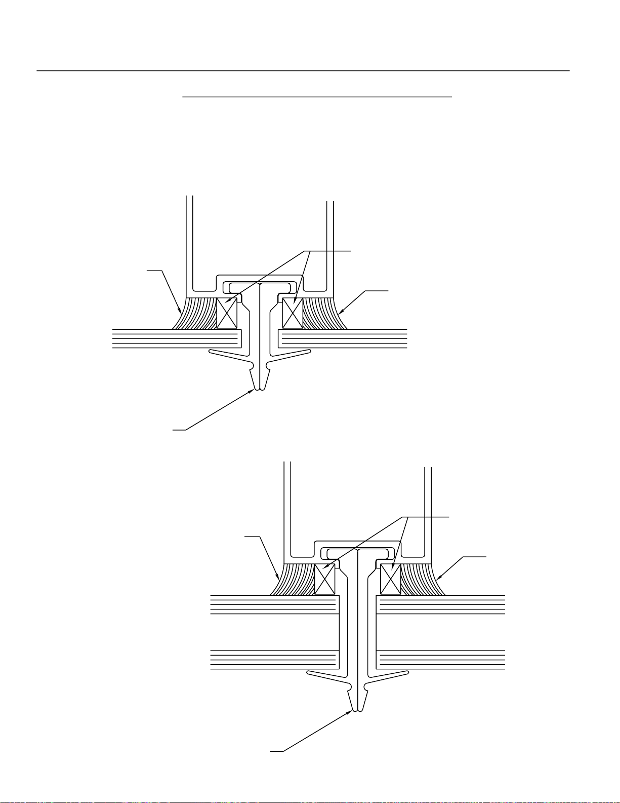
STEP 1)
JAMB
Glazing gasket (W164) will be continuous in the head / sill cans.
The jamb gasket will run between. The gasket will run across
the front of the butt glazed vertical. The glass will be installed
from the exterior; install the interior gasket as follows.
Start by pushing the gasket in place at the ends. Move to
the middle, then to quarter points and work the "WAVES" toward
the ends.
DO NOT STRETCH THE GASKET OR IT WILL RETURN
TO ITS ORIGINAL FORM, CREATING GAPS AT THE GASKET
INTERSECTIONS.
See Fig. 40 below.
HEAD
GASKET LENGTH = D.L.O. + 2%
8" - 12"
VARIES
GASKET RUNS TO JAMB
SEALANT
STEP 2)
JAMB GA S KET TO
RUN THRU.
SILL
BEFORE THE GASKETS ARE INSTALLED, SEAL 1"
VERTICALLY AND HORIZONTALLY IN THE GASKET
RACES WITH SILICONE T YPE SEALANT AT ALL
CORNER S . AFTER INSTAL LATION SEAL THE ENDS
OF ALL GASKETS. SEALING RACES & GASKET END IS
REQUIR ED AT TH E INTERI OR OF THE SYSTEM.
EXTERIOR SEALANT AT RACE AND GASKETS ARE
OPTIONAL.
GASKET RUNS TO JAMB
BUTT GLAZED
VERTICAL
[FIG. 40]
Install setting block assemblies at 1/4 points in the sill can glazing
pockets. See Fig. 41 below.
W164
HNA1 - 901
HNA2 - 903
9485
9479
HN33 - 902
HN34 - 904
FU08 @ 1G66
902 I-BAR CAN
W164
9485
9484
[FIG. 41]
CDB 9/2009
Page 40

PAGE 38
SECTION V A - GLAZING PROCEDURES
STEP 3)
BUTT GLAZED
MULLION
FOR BUTT GLAZED VERTICAL
(CONT.)
Refer to page 17 for the cut lengths for the butt glazed mullions.
Cut the can fillers to the correct length to position the vertical mullions
on the required center lines. Refer to page 31 to set the mullions.
Install the glazing gasket to the interior gasket track as shown below.
GASKET RUNS THRU
AT VERTICALS
CAN
FILLER
JAMB
CAN
FILLER
JAMB
GLASS STOP
STEP 4)
CENTER LINE
OF MULLION
CENTER LINE
OF MULLION
[FIG. 42]
Fill the cavity in the vertical mullion behind the glazing gasket with
silicone sealant, 3/8" above and below the gasket. This should be
done at the head and sill can before the glass units are installed.
See Fig. 43 below.
FILL THIS CAVITY BEHIND
THE GLAZING GASKET
AT HEAD & SILL CANS
BEFORE INSTALLING
THE GLASS UNITS
[FIG. 43]
DPS 7/2001
Page 41

PAGE 39
SECTION V A - GLAZING PROCEDURES
STEP 5)
FOR BUTT GLAZED VERTICAL
(CONT.)
Apply WM10 (2 sided tape) to the butt glazed mullion vertically, from
head can gasket track to sill can gasket track, located on the butt
glazed mullion as shown below.
DO NOT remove the exterior protective film until the glass unit has been
set and positioned correctly.
1/2"
STEP 6)
BUTT GLAZED
MULLION
WM10
3/8" x 1/2" TAPE
[FIG. 44]
Follow the glass setting procedure as detailed in
Fig. 45 below and Fig. 46 on page 40.
GASKET RUNS THRU
AT VERTICALS
JAMB
JAMB
GLASS STOP
INSTALL THIS UNIT
- LAST -
INSTALL THIS UNIT
- 2nd TO LAST -
[FIG. 45]
DPS 7/2001
Page 42

PAGE 40
SECTION V A - GLAZING PROCEDURES FOR
BUTT GLAZED VERTICAL
(CONT.)
STEP 7) Lift the gl ass into the head ca n gl azin g pocket. Then set it
down on the setting blocks in the sill can glazing pocket, and
slide the glass horizontally into proper position.
NOTE: If there are no vertical intermediates being used, proceed to
nstall the exterior glazing gasket as described at Step 1 on page 37.
9484
HEAD
1/2"
G.B.
N
U
S
S
LA
G
I
9485
W102
T
QUICK SET
HN33
SILL
1/2"
G.B.
[FIG. 46]
W102
9485
9484
DPS 6/2003
Page 43

PAGE 41
SECTION V A - GLAZING PROCEDURES
STEP 8)
A)
FOR BUTT GLAZED VERTICAL
(CONT.)
WHEN THE GLASS UNITS ARE POSITIONED CORRECTLY-
At the jamb, install the glazing stop and the vertical glazing gasket.
2 PC. JAMB
JAMB
GLASS STOP
[FIG. 47]
1/2"
Remove the exterior protective film on the glazing tape and press the
B)
glass units into contact with the now exposed adhesive.
Vertical glass size formula is DLO + 1". Horizontal glass size
formula is DLO + 1 1/2" between butt glazed mullions, and
DLO + 1 1/4" between butt glazed mullions and captured jambs.
GLASS UNIT
3/4"
GLASS
BITE
1/2"
GAP
Quick Set
GASKET RUNS THRU
AT VERTICALS
BUTT GLAZED
MULLIONS
GLASS UNIT
3/4"
GLASS
BITE
3/4"
GLASS
BITE
1/2"
GAP
GLASS UNIT
3/4"
GLASS
BITE
[FIG. 48]
JAMB
1/2"
GLASS
BITE
DPS 12/2002
Page 44

PAGE 42
SECTION V A - GLAZING PROCEDURES
FOR BUTT GLAZED VERTICAL
(CONT.)
FOR SAFETY, THE USE OF GLAZING CLIPS IS RECOMMENDED.
STEP 9)
Locate the glazing clips with a spacing of 24" on center maximum.
See Fig. 49 and Fig. 50 below.
WM10
HV11
901/903
[FIG. 49]
HV10
902/904
24" MAXIMUM
GLASS UNIT
STEP 10)
BUTT GLAZED
MULLION
HOOK THE TEMPORARY GLAZING CLIPS
INTO THE MULLION CAVITY AND SLIDE
THEM TOGETHER UNTIL THE CLIPS
ARE BACK TO BACK.
GLASS UNIT
[FIG. 50]
Install the exterior glazing gasket in the same manner as
described in Step 1, page 37.
DPS 7/2001
Page 45
PAGE 43
SECTION V A - GLAZING PROCEDURES
STEP 11)
STRUCTURAL
SILICONE
FOR BUTT GLAZED VERTICAL
(CONT.)
Apply the structural silicone to the interior side tying the
mullion, spacer tape, and glass unit together.
WM10
STRUCTURAL
SILICONE
HV11
901/903
STRUCTURAL
SILICONE
[FIG. 51]
WM10
STRUCTURAL
SILICONE
[FIG. 52]
HV10
902/904
DPS 7/2001
Page 46

PAGE 44
SECTION V A - GLAZING PROCEDURES
STEP 12)
FOR BUTT GLAZED VERTICAL
After the interior sealant has cured, typically an overnight setup is
required. Then remove the temporary glazing clips and proceed with
filling the void between the glass units at the exterior with backer
rod and structural silicone sealant for a weather tight seal.
Remove excess silicone from the glass surface for a neat and
professional appearance.
See Fig. 53 below.
(CONT.)
SEE THE SILICONE MANUFACTURER’S
INSTRUCTIONS FOR APPLICATION
[FIG. 53]
OF WEATHER SEAL.
NOTE:
THE SUCCESS OF STRUCTURAL SILICONE GLAZED PROJECTS HAS
BEEN THE RESULT OF COMPATIBILITY TESTS PERFORMED ON
ACTUAL MATERIALS SUPPLIED TO THE PROJECT. THE INSTALLER
MUST MAKE SURE THAT SUCCESSFUL COMPATIBILITY TESTS ARE
PERFORMED IN ACCORDANCE WITH THE SILICONE MANUFACTURER’S
RECOMMENDATIONS AND PROCEDURES.
DPS 7/2001
Page 47

PAGE 45
SECTION V B - GLAZING PROCEDURES
FOR BUTT GLAZED VERTICAL AND INTERMEDIATE HORIZONTAL
STEP 1)
WHEN A HORIZONTAL INTERMEDIATE IS BEING USED,
GLASS SETTING OPTIONS INCLUDE INSIDE/OUTSIDE
GLAZING OPPORTUNITIES. THE GLASS ABOVE THE
HORIZONTAL WILL BE SET FROM THE OUTSIDE, AND
THE GLASS BELOW MAY BE SET FROM THE OUTSIDE
OR THE INSIDE. SEE FIG. 54 BELOW.
HEAD
1/2"
GLASS BITE
NOTE:
GLASS ABOVE HORIZONTAL
MUST BE OUTSIDE GLAZED.
SNAP ON HORIZONTAL
FACE AFTER ALL LITES
ARE SET.
(1) Tip the glass into the head
glazing pocket.
(2) Raise the glass to clear the
setting blocks.
(3) Set the glass on the setting blocks.
1
3
HORIZONTAL
2
-OPTIONAL AT LOWER LITE-
The glass unit may also be set
as described for the top lite,
except from the inside.
2
(1) Tip the glass back to
set on the setting block.
(2) Tip the glass to vertical.
(3) Install the face cover.
Quick Set
3
1
1/2"
GLASS BITE
SILL
3a
1a
2a
(1a) Hold the glass vertical.
(2a) Rotate the glass to the
glass plane.
(3a) Set the glass on the
setting blocks.
[FIG. 54]
DPS 12/2002
Page 48

PAGE 46
SECTION V C - GLAZING PROCEDURES
FOR CAPTURED VERTICAL MULLION
AND INTERMEDIATE HORIZONTAL
WHEN USING A CAPTURED VETICAL MULLION, THE GLASS SIZE
FORMULA IS DLO + 7/8" HORIZONTALLY AND VERTICALLY.
NOTE:
When using a captured vertical mullion, glass setting tends to
become easier because the number of removable stops per
opening increases. The same glass setting options included in
Section V B will be available with this mullion, and the inside glass
setting of the top lite becomes available also.
See Fig. 55 below.
2 pc. JAMB
REMOVABLE VERTICAL
STOPS
REMOVABLE
VERTICAL
STOPS
HORIZONTAL STOP
RUNS THRU
[FIG. 55]
REMOVABLE
VERTICAL
STOPS
DPS 7/2001
Page 49

PAGE 47
SECTION VI A - DOOR FRAME INSTALLATION
NOTE: If an entrance frame is required, it must be installed first.
See the parts description pages in SECTION II for the appropriate
door jamb and transom bar for the system being used.
STEP 1)
STEP 2)
STEP 3)
STEP 4)
NOTE:
Correctly locate the entrance frame in the opening.
Apply a bead of sealant around the interior portion of the jamb
to set the member into. Tie the side lite sealant or condition
sealant into the bead of sealant to be applied under the threshold.
The concept is to have a continuous bead of sealant at the interior
connected from the side lite sill can/condition through the door
jamb, continuing under the threshold to the opposite jamb and
onto the opposite side lite sill can.
Set the assembled door frame in the opening, plumb and level.
Anchor the door frame and threshold as indicated below in Fig. 56 below
and also in Fig. 57 through Fig. 60 on page 48.
THRESHOLD FASTENER
SIDE LITE SILL CAN
12" FROM JAMB & 12" O.C.
(3) PER SINGLE DOOR
The door jamb runs to the
floor and is cut longer
than any other vertical
member.
K-124/K-125 Threshold Clip & Screws
@ Offset Pivots & Butt Hinges
K-153/K-154 Threshold Clip & Screws
@ Concealed Rod Panic
THRESHOLD
[FIG. 56]
12" MAX.
(9950)
CONTINUOUS BEAD
OF SEALANT
DPS 7/2001
Page 50

PAGE 48
SECTION VI A - DOOR FRAME INSTALLATION
K273 RH
K274 LH
9593
1/4" Dia. Weep
at 1/4 Points
(CONT.)
5/8"
9593
K273 RH
K274 LH
9914
W138
At condition, attach through
the header with flat head
screws, located 6" from
[FIG. 57]
the ends and 24" on center,
maximum spacing.
Attach through the threshold with flat head screws.
12" from jambs and 12" on center max.
EXTERIOR INTERIOR
[FIG. 59]
9914
W138
[FIG. 58]
Continuous bead of sealant at
the back of the threshold and sides of the
jambs, and tied into mullion sealant
at the condition.
Quick Set
DOOR JAMB SET IN SEALANT
SIDE LITE
9154/9155
W138
ANCHOR THROUGH THE JAMB
AT THE DOOR LOCATION.
FRAMING
THRESHOLD
CLIP
[FIG. 60]
SEE THE DOOR AND HARDWARE INSTALLATION INSTRUCTIONS
FOR MORE DETAILED STEPS, PART # Y015.
9154/9155
W138
JDA 3/2002
Page 51

PAGE 49
SECTION VI A - DOOR FRAME INSTALLATION
CONT.
TRANSOM/JAMB GLAZING ADAPTOR ANCHORING
Use the Transom/Jamb Glazing Adaptor (ext. #9295) with Jamb #9597, Glazing Stop
#9133 and 1/4" Glazing Adaptor #9261 at 901. At 902, use the Transom/Jamb Glazing
Adaptor #9295 with Jam #9592 and Glazing Stop #9133.
Anchor the Transom/Jamb Glazing Adaptor as shown in Fig. 61.
9295
STT6
16" MAX. O.C. 16" MAX. O.C. 16" MAX. O.C.
[FIG. 61]
REMOVEABLE GLASS STOP CUT LENGTH AND FABRICATION
Removeable Glass Stop (ext. #7861)
Cut length = Head Length - 1/16".
NOTCH THESE SURFACES
1/4" (AS SHOWN)
TYPICAL AT EACH END
1/4"
4"4"
11/16"
[FIG. 62]
BAB 11/2001
Page 52

PAGE 50
SECTION VI A - DOOR FRAME INSTALLATION
CONT.
TRANSOM HEADER AND APPLIED TRANSOM GLAZING
9539 @ 902
(901 SIMILIAR)
K267 CLIP @ 902
K277 CLIP @ 901
SEALANT
9592 DOOR JAMB @ 902
(901 SIMILIAR)
9484 HEAD CAN
AT THE SIDE LITE
TYP. @ 902
(901 SIMILIAR)
SEALANT
#STT6
SCREWS
[FIG. 63]
9295
SET IN A BEAD OF SEALANT VERTICALLY
Slide the header clip onto the end of the header. Drill and fasten the clip to the header
with the screws provided in the clip package.
Temporarily locate the header / clip combination at the correct mounting position to
locate and drill the mounting holes for the clip into the jamb.
Apply sealant to the ends of the header and install with the screws provided.
Attach the header to the condition with 1/4" diameter fasteners minimum, 6" from
the jambs and 16" on center maximum.
Apply a thin bead of sealant vertically to set the screw applied glazing stop into. Then
fasten into place with #STT6 screws, 4" from the ends and 12" on center maximum.
Apply sealant to the ends of the header and vertical glazing adaptor as shown in
Fig. 63 above.
BAB 11/2001
 Loading...