

Page 1
Installation Instructions Sections 1 - 15
March 2013
PART NO. Y80A
Page 2

Series 8700 / 8800 Unitized Curtain Wall Installation Instructions
Series 8700 / 8800 Unitized Curtain Wall Installation Instructions
Table Of Contents
SECTION PAGE
1. General Notes and Guidelines…………………………………………………………..
2. Parts Identification…………………………………………………………………………
3. Static Starter Sill Preparation and Installation……………………………..…………
4. Dynamic Starter Sill Preparation and Installation…………………..………………..
5. Dynamic Starter Sill Anchor Installation………………………………………………
6. Intermediate Floor Slab Anchor Installation……………………………………….....
7. Unit Inspection and Preparation for Installation……………………………..….......
8. Setting Units at Static Starter Sills………………………………………………..…....
9. Setting Units at Dynamic Starter Sills………………………………………………….
10. Setting Typical Intermediate Units………………………………………………...……
11. Setting Assembled (One Piece) Corner Units….....................................................
12. Applying Critical Seals……………………………………………………………………
13. Apply Typical Perimeter Seals…………………………………………………………..
14. Deglaze / Re-glaze Procedures - Captured System................................................
15. Deglaze / Re-glaze Procedures - SSG System…….................................................
3 - 4
5 - 8
9 - 16
17 - 26
27 - 28
29
30 - 31
32 - 36
37 - 44
45 - 51
52 - 55
56 - 57
58 - 60
61 - 63
64 - 68
Minimizing Condensation
Note: Please reference EFCO's "Understanding Condensation" brochure which can be obtained through your EFCO
representative.
Condensation will form on any surface when unfavorable conditions (interior temperature and relative humidity and
exterior temperature) are present. When the formation of excessive condensation is a concern, it is highly recommend ed that a
design professional is utilized to perform an analysis of the shop drawings to recommend the best possible installation methods.
Please contact your EFCO representative for information on EFCO's Thermal Analysis Services.
Many current installation practices lead to an increase in the possibility of the formation of condensation. Though not all
inclusive, the list of examples below illustrates conditions under which condensation is lik ely to occur:
1. Bridging system thermal break with non-thermally broken metal flashin g or lintels that are exposed to the
exterior
2. System exposure to cold air cavities
3. Interior relative humidity levels not maintained at recommended levels, see EFCO’s “Understanding
Condensation” brochure
4. Inadequate separation between system and surrounding condition at perimeter
5. Product combinations during the shop drawing stage that result in bridging thermal breaks
of one or all products involved
Note: Assembly Instructions are provided as a supplement, and should be used in conjunction with the approved shop drawings.
EFCO 2011 Page 2
Page 3

Series 8700 / 8800 Unitized Curtain Wall Installation Instructions
Section 1: General Notes And Guidelines
HANDLING / STORING / PROTECTING ALUMINUM
The following guidelines are recommended to ensure early acceptance of your
products and workmanship.
A. HANDLE CAREFULLY - Store with adequate separation between
components so the material will not rub together. Store the material off the
ground. Protect materials against weather elements and other
construction trades.
B. KEEP MATERIAL AWAY FROM WATER, MUD, AND SPRAY - Prevent
cement, plaster, and other materials from contacting with and damaging
the finish. Do not allow moisture to be trapped between the finished
surface and the wrapping material.
C. PROTECT MATERIALS AFTER ERECTION - Wrap or erect screens of
plastic sheeting over material. Cement, plaster, terrazzo, and other
alkaline materials are very harmful to the finish and are to be immediately
removed with soap and water. Under no circumstances should these
materials be allowed to dry or permanent staining may occur.
GENERAL GUIDELINES
The following practices are recommended for all installations:
A. REVIEW CONTRACT DOCUMENTS – Become thoroughly familiar with
the project. Check shop drawings, installation instructions, architectural
drawings and shipping lists. The shop drawings take precedence and
include specific details for the project. Shop drawings govern when
conflicting information exists in the assembly and installation instructions.
Note any field verified notes on the shop drawings prior to installing.
EFCO assembly and installation instructions are general in nature and
cover many conditions.
B. INSTALL ALL FRAMING MATERIAL PLUMB, LEVEL, AND TRUE –
Proper alignment and relationships to benchmarks and column
centerlines, as established by the architectural drawings and the general
contractor, must be maintained.
C. ERECTION SEQUENCE - The sequence of erection should be
coordinated with the project general contractor to prevent delays and
minimize the risk of material damage. Note: When preset anchors are
required, coordinate and supervise anchor and insert placement with the
general contractor including insert layout drawings, where required.
Manufacturing, assembly, glazing, and shipment of the preglazed units
must be carefully coordinated with the general contractor to ensure a
continuous and sustained flow of materials to the appropriate areas of the
project to meet the project schedule.
D. PERIMETER CONDITIONS - Verify that all job site conditions and
accompanying substrates receiving the installation are in accordance with
the contract documents. If deviations occur, notification must be given in
writing to the general contractor and differences resolved before
proceeding further with the installation in the area in question.
E. ISOLATION OF ALUMINUM - Prevent all aluminum from coming in direct
contact with masonry or dissimilar materials by means of an appropriate
primer. Typical slab anchors may be set directly onto concrete surfaces in
a block-out pocket at the edge of the slab. The block-out pocket is later
filled in with grout thereby covering the slab anchor. In such cases, a
heavy coat of zinc chromate or bituminous paint must be pre-applied to
the slab anchor.
F. SHIPMENT VERIFICATION - Verify contents of all material shipments
received upon their arrival. Verify quantity and correct finishes. Notify
EFCO immediately of any discrepancies or damage that may have
occurred.
G. SEALANT - All sealant must meet [ASTM C 920, CLASS 50]. For the
purposes of these instructions, sealant is to be defined as the following:
SEALANT - A weather resistant, gunnable liquid filler which when cured
provides a resilient, flexible (± 50% movement capability min.) air and
water seal between similar and dissimilar materials.
All sealant must be compatible with all surfaces on which adhesion is
required, including other sealant surfaces. All frame surfaces should be
clean, dry, dust, and frost free. If a primer is required, it must be applied to
clean surfaces. All perimeter substrates shall be clean and properly
treated to receive sealant. All sealants and primers must be applied
according to the sealant manufacturers instructions and
recommendations.
This system is designed and has been tested to utilize silicone sealants at
all internal joineries, i.e., joint plugs, gasket intersections, etc.
EFCO 2009 Page 3
Page 4
Series 8700 / 8800 Unitized Curtain Wall Installation Instructions
Section 1: General Notes And Guidelines
It is the responsibility of the glazing contractor to submit a statement from
the sealant manufacturer indicating that glass and glazing materials have
been tested for compatibility and adhesion with glazing sealants, and
interpreting test results relative to material performance, including
recommendations for primers and substrate preparation required to obtain
adhesion. The chemical compatibility of all glazing materials and framing
sealants with each other and with like materials used in glass fabrication
must be established.
Maintain caulk joints as shown in the approved shop drawings. A 1”
minimum joint is required at the head and jamb condition to accommodate
installation, building movements, and thermal expansion and contraction.
H. STRUCTURAL SEALANT JOINTS - The maximum allowable size of the
glass lite is controlled by the width and depth of the structural silicone joint
combined with the specified design wind load (PSF or Pa). The stress on
the structural silicone must not exceed 20 PSI (137 KPa) for a 6:1 safety
factor.
In order to determine the structural silicone sealant contact width or bite
which adheres the glass to the frame, a calculation must be performed on a
job by job basis. The formula which determines the sealant width is based
on using a trapezoidal load distribution rule. This formula is expressed as
follows:
Structural Sealant = 0.5 x Short Span (ft) x Wind load (lb/ft²)
Bite or Contact Width (in) Sealant Design Strength (=20 lb/in²) x 12 in/ft
Example: Lite size is 4’0” x 5’0” and wind load for the project is 60 psf.
Structural Sealant = 0.5 x 4’ x 60 psf
or 120 or .500”
Bite or Contact Width (in) 20 x 12 240
Sealant manufacturers, as a general rule, specify the structural sealant
depth (glue line) to be one half of the contact width for a 2:1 width to height
ratio. The glue line should not exceed 3/8” thickness nor be less than 1/4”
thick. The standard joint size for Series 8000 is 1/2” x 1/4”. Note: Weather
seals must be applied a minimum of four hours after the application of the
SSG sealant joint to allow for proper cure time.
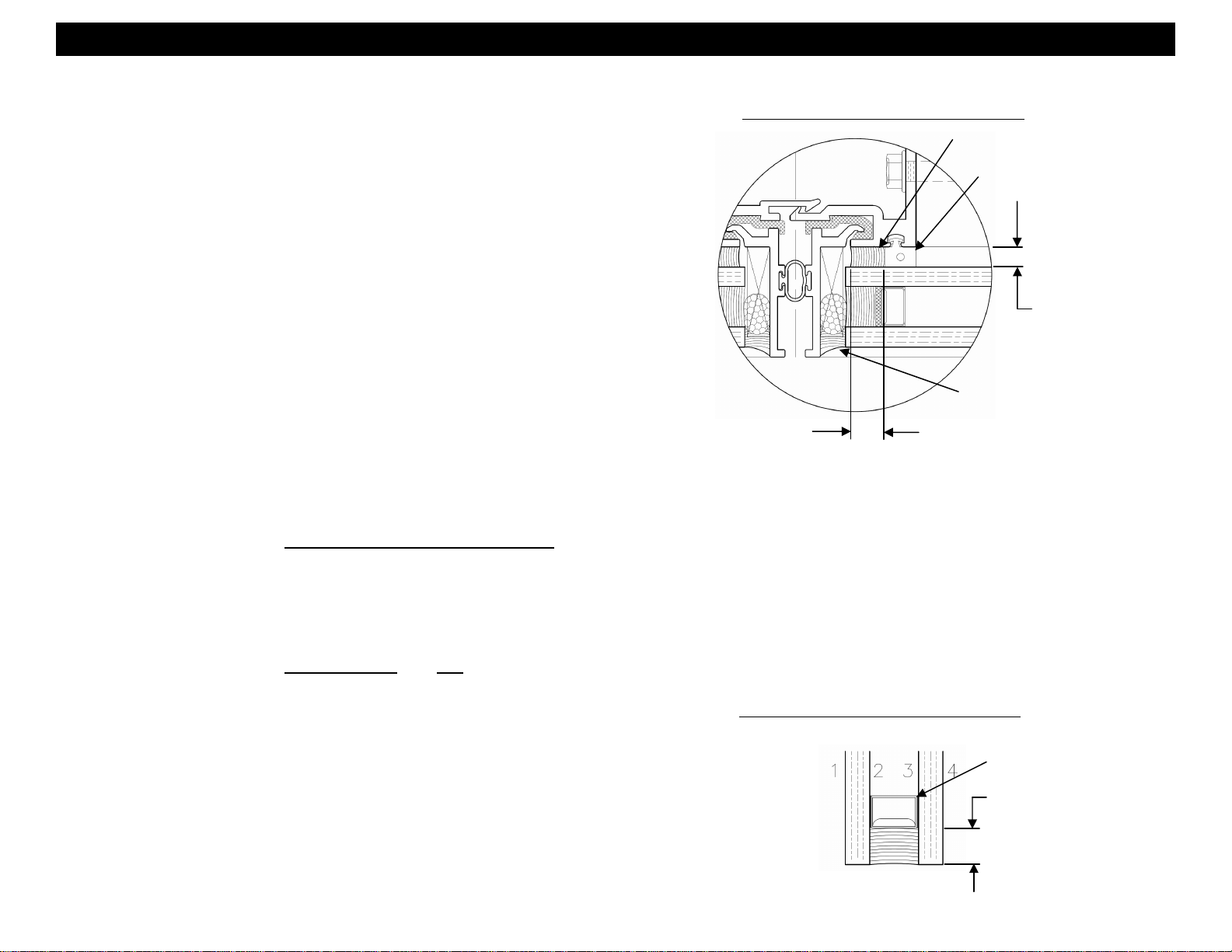
SECONDARY SEALANT JOINT DETAIL
SSG SEALANT JOINT
SPACER GASKET
SEALANT DEPTH
(GLUE LINE)
WEATHER SEAL
(Do not apply until the
STRUCTURAL SEALANT
CONTACT WIDTH
SSG sealant joint has
cured for 4 hours.)
I. SECONDARY SEALANT JOINT DESIGN - The design of the secondary
sealant joint is based on the 50:50 load sharing principal where the I.G. unit
is comprised of two symmetrical lites of glass. The secondary sealant joint
that adheres the two lites of glass together only carries half the wind load
applied to the I.G. unit. Since the load is halved, the secondary sealant
contact width is half that of the SSG joint. Using the example earlier for the
1/2” x 1/4” SSG joint, the secondary sealant contact width for the I.G. unit in
the example is 1/4”.
Edge deletion is required on the coated surface (#2 or #3) for hard or soft
coated glazing products.
SECONDARY SEALANT JOINT DETAIL
STANDARD TUBULAR
SPACER RECOMMENDED
SECONDARY SEALANT
CONTACT WIDTH
EFCO 2009 Page 4
Page 5

Series 8700 / 8800 Unitized Curtain Wall Installation Instructions
Section 2 - Parts Identification
EXTRUSION
Profile Part #
4G99
1H62
7" STATIC STARTER SILL U4G99-001, U4G99-002
8" STATIC STARTER SILL U1H62-001, U1H62-002
Description
17C8
FABRICATED #
FM01, FM22-
FM25
7" GUTTER BASE MULLION
ANCHOR
17H9
FABRICATED #
FM02, FM26-
FM29
8" GUTTER BASE MULLION
ANCHOR
Tooling Drawing/Cut Formulas
REFERENCE FM01, FM22-FM25
PART DRAWINGS
REFERENCE FM02, FM26-FM29
PART DRAWINGS
U17C6-001, U17C6-002, U17C6-003
17C6
17D4
EFCO 2009 Page 5
STARTER SILL ANCHOR
UNIT SLAB ANCHOR
U17C6-004, U17C6-005, U17C6-006
U17C6-007
U17D4-001, U17D4-002, U17D4-003
U17D4-004
Page 6

Series 8700 / 8800 Unitized Curtain Wall Installation Instructions
Section 2 - Parts Identification
EXTRUSION
Profile Part #
17C3
17H8
17C5
17H7
17D3
7" CAPTURED AND SSG DYNAMIC
STARTER SILL
8" CAPTURED AND SSG DYNAMIC
STARTER SILL
7" DYNAMIC STARTER SILL
GUTTER BASE
8" DYNAMIC STARTER SILL
GUTTER BASE
SERRATED WASHER
Description
Tooling Drawing/Cut Formulas
U17C3-001, U17C3-002, U17C3-003,
U17C3-004, U17C3-005
U17H8-001, U17H8-002, U17H8-003,
U17H8-004, U17H8-005
U17C5-001, U17C5-002, U17C5-003,
U17C5-004, U17C5-005
U17H7-001, U17H7-002, U17H7-003,
U17H7-004, U17H7-005
AS REQUIRED PER STRUCTURAL
CALCULATIONS
17D5
17C4
FABRICATED #
FM09
17D0
FABRICATED #
FM10
STACK SILL TRIM
DYNAMIC STARTER SILL GUTTER
REVEAL SPLICE
STACTIC STARTER SILL GUTTER
REVEAL TUBE SPLICE
CUT TO LENGTH - HORIZ. UNIT DIM.
MINUS .125
REFERENCE FM09 PART DRAWING
REFERENCE FM10 PART DRAWING
17L6
FABRICATED #
FM12
EFCO 2009 Page 6
TEMPORARY GLAZING RETAINER REFERENCE FM12 PART DRAWING
Page 7

Series 8700 / 8800 Unitized Curtain Wall Installation Instructions
Section 2 - Parts Identification
EXTRUSION
Profile Part #
17D6
FABRICATED #
FM03
17J3
FABRICATED #
FM04
7" STACK SILL MULLION
ANCHOR BAR
8" STACK SILL MULLION
ANCHOR BAR
Description
17D1
FABRICATED #
FM11
17D2
FABRICATED #
FM05 & FM06
MULLION ANCHOR
HOOK ANCHOR LEFT (FM05)
HOOK ANCHOR RIGHT (FM06)
Tooling Drawing/Cut Formulas
REFERENCE FM03 PART
DRAWING
REFERENCE FM04 PART
DRAWING
REFERENCE FM11 PART
DRAWING
REFERENCE FM05 AND FM06
PART DRAWINGS
17F3
FABRICATED
FM07
17F4
FABRICATED
FM08
EFCO 2009 Page 7
90° OUTSIDE CORNER
MULLION ANCHOR
90° INSIDE CORNER MULLION
ANCHOR
REFERENCE FM07 PART
DRAWINGS
REFERENCE FM08 PART
DRAWINGS
Page 8

Series 8700 / 8800 Unitized Curtain Wall Installation Instructions
Section 2 - Parts Identification
FASTENERS
Profile
ACCESSORIES
Part #
SFQ5
M171
1/4"-14 X 1 1/2" HX- SMS 18-8 B
1/4"-14 X 1 1/2" HWH #3 UC TEK 3 SG
Description
M170 1/2"-13 X 1/2" SHSS W/ CP - STEEL
M169
WC19
LC23
WC20
WC21
WVD2
WC16
1/2"-13 X 3 1/2" HX-MS 18-8 (FULL THREAD)
HORIZONTAL STACK JOINT SEAL GASKET
HORIZONTAL STACK SPACER GASKET BLACK RIGID PVC
FIN BAR BULB GASKET 70 SHORE "A" DURO BLACK EPDM
VERTICAL STACK JOINT SEAL GASKET 60 SHORE "A" DURO BLACK SILICONE
90° CORNER AIR SEAL GASKET 70 SHORE "A" DURO BLACK EPDM
FIN BAR PRESET ISOLATOR GASKET 85 SHORE "A" DURO BLACK SILICONE
Material
60 SHORE "A" DURO BLACK EPDM
HC07
HC08
HC09
EFCO 2009 Page 8
FOAM CAULK BACKER 3/4” X 3/4” X 8” L-200 MINICELL FOAM CAULK BACKER
SSG STACK JOINT GUTTER SPLICE
GUTTER SPLICE 4 13/16” X 4 13/16” X 1/16”
CAPTURED STACK JOINT GUTTER SPLICE
GUTTER SPLICE 5 1/4” X 5 1/4” X 1/16”
50 SHORE "A" DURO BLACK SILICONE
50 SHORE "A" DURO BLACK SILICONE
Page 9
Series 8700 / 8800 Unitized Curtain Wall Installation Instructions
Section 3 - Static Starter Sill Preparation and Installation
Projects will be produced by EFCO in one of three ways: 1) As a stock length product whe re all fabrication, assembly, and glazing will be performed by
the customer, or: 2) Prefabricated “knock down” where EFCO fabricates the materials, and the customer performs the assembly, and glazing, or:
3) EFCO will provide a completely fabricated, assembled and glazed product. The materials shown here in the installation instructions may be received
in the field with varying degrees of shop assembly, with some items shop installed, and other items to be field installed. Certain assembly and install ation
procedures shown and described in this document may be performed in the shop or the field at the discretion of the assembler.
1. Preparation of the Static Starter Sill:
a. The static starter sill may have an end dam pre-attached and sealed at the jamb condition. Ensure that the end dam is properly applied and sealed
to the starter sill as described below. This is a critical seal and the joint must be carefully tooled to create a watertight seal. See Figures 1, 2, and 3.
b. The starter sill may have gaskets (WC19 and LC23) pre-applied. The LC23 is cut to the length of the starter sill while the WC19 will be
approximately 6” to 8” longer than the starter sill. Do not cut off excess WC19. The excess gasket will be slid into the adjacent starter sill during
installation.
c. Plug the end of the tubular section of the starter sill at the jambs and corner conditions by recessing backer rod at least 1/4” into the end of the tube.
Fill the voids in the tube and between the thermal struts with sealant and tool smooth. Intermediate splice locations incorporate an int ernal splice
sleeve and will be covered later in this section.
Clean all sealant contact surfaces using an approved solvent or cleaner of all oils and other contaminants. The sealant manufacturer’s
preparation and application instructions should be followed exactly. If sealant primer is required, apply it per the primer/sealant
manufacturer’s instructions.
LC23
WC19
M153
Silicone Sealant
End Dam - Attach
with (1) M153
Figure 1
Ensure LC23 and WC16
butt into the end dam fully.
Tool sealant smooth
into joints.
Plug with backer rod and fill the voids in
the tube and between the thermal struts
with sealant and tool sealant smooth.
Figure 3
Figure 2
EFCO 2009 Page 9
Page 10

Series 8700 / 8800 Unitized Curtain Wall Installation Instructions
Section 3 - Static Starter Sill Preparation and Installation
d. A gutter base anchor (FM01 or FM02) is required at each intermediate vertical and jamb. Two are required at corner mullion conditions. The
anchors are used to transfer wind load reactions from the verticals into the anchoring system. Before installation of the static starter sill, slide the
appropriate number of gutter base anchors into each section of starter sill. See Figures 4 and 5.
e. Slide the gutter base anchors into final position after the starter sill anchor bolts have been applied.
Plug with backer rod and
fill the voids in the tube
and between the thermal
struts with sealant and
tool sealant smooth.
Slide gutter base anchors
into the static starter sill.
Figure 4
Leave tube open to receive
splice at intermediate splice
locations.
Slide gutter base anchors into
the static starter sill at corners.
Figure 5
EFCO 2009 Page 10
Page 11

Series 8700 / 8800 Unitized Curtain Wall Installation Instructions
Section 3 - Static Starter Sill Preparation and Installation
2. Verify that all job site conditions and accompanying substrates receiving the installation are in tolerance and are in accordance with the contract documents.
3. Pre-cleaning the substrates where the caulk joints will be applied later may be advisable prior to setting the starter sill. Final cleaning and sealant primer
application where required should be performed only immediately before caulk joint sealant applicatio n.
4. Use established bench marks to ensure the accuracy of the starter sill location. Precise measurements and coordination with regard to established bench
marks are critical to ensure that the starter sills are installed in the correct location. Improperly installed, or miss-located starter sill s will cause significant
problems for the remainder of the erection process.
Apply shim between end
dam and condition.
Slide base anchor away
from anchor location.
Static Starter Sill
Apply shims between
starter sill and condition.
Figure 6
EFCO 2009 Page 11
Page 12
Series 8700 / 8800 Unitized Curtain Wall Installation Instructions
Section 3 - Static Starter Sill Preparation and Installation
5. Starting at the jamb, place the starter sill into the opening hard on the condition in the final position, excluding elevation. Match drill the substrates at the
anchor locations and apply the anchors allowing for shim space under the starter sill. Refer to the approved shop drawi ngs for type, size, and specific anch or
details. Shim the starter sill to the proper elevation height making sure the starter sill is level. The shims used must be full bearing shims. The shims must
fully support the entire load bearing surface of the starter sill at each anchor location. Refer to the project structural calculation package and final approved
shop drawings for detailed information.
6. EFCO recommends minimum of a 1/2” caulk joint between the starter sill and the condition.
7.
When applying anchor bolts to the starter sill, pre-fabricated serrated washers (17D3) must be used. The serrate d wa shers will lock the starter sill into
position when the anchor bolt is tightened. See Figures 7, 8 and 9. After verifying the final position of the starter sill, secure the anchor bolts as required.
8.
Put a temporary shim between the end dam and the condition to protect the end dam during unit installation. The required shim thickness will vary due to
field tolerances and project specific joint size requirements, but a minimum of 1/2” is reco mmended. Remove the shim after unit installation.
Slide base anchors
Anchor bolts as required.
Shim starter sill to
proper elevation
into final position after
securing anchors.
height.
Serrated Washer
Static Starter Sill
Slide base anchors into final position
after securing anchor bolts.
Figure 7
Apply shim between end
dam and condition.
Static Starter Sill
Pre-fabricated oversized
anchoring slot.
Shim starter sill to
proper elevation height.
Figure 8
Static Starter Sill
Anchor bolts as required.
Figure 9
EFCO 2009 Page 12
Page 13

Series 8700 / 8800 Unitized Curtain Wall Installation Instructions
Section 3 - Static Starter Sill Preparation and Installation
9. Using an approved solvent or cleaner, clean the sealant contact surfaces of the corner splice joint of all oils and other contaminants.
10.
The starter sill will be spliced at corner conditions. Refer to the approved shop drawings for project specific joint size. A minimum joint size of 1/4” is required.
11. Slide the two starter sill sections together while threading WC19 gasket into the adjacent gutter gasket reglet.
12. Seal the ends of the WC19 gaskets and butt them together. Ensure the gaskets are not stretched while performing this task.
13. Anchor the new starter sill section ensuring the starter sill is level and while maintaining the appropriate joint size at the splice joint.
14. Slide the base anchors into the corner, butting them together.
15. Apply sealant into the joint between the sections of starter sill and tool smooth to create a water tight seal. Use backer rods in the joint where
appropriate. The splice joint width will vary per project requirements. See Figure 12.
Thread WC19
gasket into
adjacent gutter
gasket reglet .
Shim starter sill to
proper elevation height.
Slide base anchors
into final position after
securing anchor bolts.
Anchor bolts as required.
Figure 11
Seal ends of gaskets
and butt together.
Static Starter Sill
Apply sealant between
90° Outside Corner
Figure 10
the two starter sills
and tool to create a
watertight seal.
Figure 12
EFCO 2009 Page 13
Page 14
Series 8700 / 8800 Unitized Curtain Wall Installation Instructions
Section 3 - Static Starter Sill Preparation and Installation
16. Using an approved solvent or cleaner, clean the sealant contact surfaces shown below of all oils and other contaminants.
17.
The starter sill should be spliced at approximately every twenty-five feet. Refer to the approved shop drawings for specific locations and conditions.
18. Apply bond breaker tape (WM 79) to FM10 splice. Apply sealant inside the splice end of the starter sill reveal tube coating the inside wall of
the tube and to the FM10 splice tube as shown in Figure 13.
19. Apply sealant inside the splice end of the adjacent starter sill and to the other end of FM10 splice as shown in Figure 14. Slide the two starter
sill sections together while inserting FM10 splice and threading the WC19 gasket into the adjoining gasket reglet. Anchor starter sills.
20. Apply sealant into the joint between the sections of starter sill and tool to create a water tight seal. The splice joint width will vary per project
requirements. See Figure 15. Seal the ends of the WC19 gaskets and butt them together.
21. Set HC09 gutter splice in a bed of sealant centered on the starter sill splice joint as shown in Figure 16. Force the splice down onto the gutter,
forcing out all air bubbles.
22. Apply sealant around the edges of the splice an tool smooth and water tight.
Bond Breaker
Tape
FM10 Tube Splice
Figure 13
Slide base anchor into
final position after
securing anchor bolts.
Apply sealant
Static Starter Sill
Thread WC19
gasket into
adjacent gutter
gasket reglet .
HC09 Gutter Splice
Figure 14
Apply sealant
Apply sealant around
entire perimeter of
gutter splice and tool to
create a watertight seal.
Anchor bolts as required.
Align bond
breaker tape and
base anchor with
the splice joint at
the starter sills.
Apply sealant between
the two starter sills
and tool to create a
watertight seal.
Serrated Washer
Figure 15
Marry the gutter
splice sealant with
the reveal splice
sealant to create a
watertight seal.
Place gutter
splice HC09 into
a bed of sealant.
Figure 16
Slide gutter splice up
under gasket track and
tool sealant to ensure a
watertight seal.
Figure 17
EFCO 2009 Page 14
Page 15
Series 8700 / 8800 Unitized Curtain Wall Installation Instructions
Section 3 - Static Starter Sill Preparation and Installation
23. Using an approved solvent or cleaner, clean the sealant contact surfaces of the corner splice joint of all oils and other contaminants.
24.
The starter sill will be spliced at corner conditions. Refer to the approved shop drawings for project specific joint size. A minimum joint size of 1/4” is required.
25. Slide the two starter sill sections together while threading WC19 gasket into the adjacent gutter gasket reglet.
26. Seal the ends of the WC19 gaskets and butt them together. Ensure the gaskets are not stretched while performing this task.
27. Anchor the new starter sill section ensuring the starter sill is level and while maintaining the appropriate joint size at the splice joint.
28. Slide the base anchors into the corner, butting them together.
29. Apply sealant into the joint between the sections of starter sill and tool smooth to create a water tight seal. The splice joint width will vary per
project requirements. See Figure 20.
Anchor bolts
as required.
Static Starter Sill
Thread WC19
gasket into
adjacent gutter
gasket reglet .
Slide base anchors
into final position after
securing anchor bolts.
Shim starter sill
to proper
elevation height.
Figure 19
Seal ends of gaskets
and butt together.
Apply sealant between
90° Inside Corner
Figure 18
Figure 20
the two starter sills
and tool to create a
watertight seal.
EFCO 2009 Page 15
Page 16
Series 8700 / 8800 Unitized Curtain Wall Installation Instructions
Section 3 - Static Starter Sill Preparation and Installation
30. As the starter sill sections are anchored into the final position, slide the gutter base anchors into position. The base anchor is flush with the end
of the starter sill at the jambs, centered on the vertical at intermediate verticals, and flush with the mitered ends of the starter sill at corner
conditions.
31. Finish installing all starter sill sections as previously described until the installation is completed.
FM01 - 7” Base Anchor
FM24 - 7” Base Anchor
FM26 - 8” Base Anchor
FM01 - 7” Base Anchor
FM02 - 8” Base Anchor
FM02 - 8” Base Anchor
FM25 - 7” Base Anchor
FM27 - 8” Base Anchor
Static Starter Sill
FM01 - 7” Base Anchor
FM02 - 8” Base Anchor
FM23 - 7” Base Anchor
FM22 - 7” Base Anchor FM29 - 8” Base Anchor
FM28 - 8” Base Anchor
Figure 21
EFCO 2009 Page 16
Page 17
Series 8700 / 8800 Unitized Curtain Wall Installation Instructions
Section 4 - Dynamic Starter Sill Preparation and Installation
1. Preparation of the Dynamic Starter Sill:
a. The Dynamic Gutter Base will be installed into the opening first. The Gutter Base may have an end dam pre-attached and sealed at the jamb
conditions. Ensure that the end dam is properly applied and sealed to the starter sill as shown below. This is a critical seal and the joint must be
carefully tooled to create a watertight seal.
b. Apply WC16 isolator gaskets into the reglets of the Gutter Base. The gaskets should be flush with each end of the gutter base, including mitered
ends at corner conditions. Do not stretch the gasket during installation.
c. Seal the ends of the WC16 isolator to the end dam.
Clean all sealant contact surfaces using an approved solvent or cleaner of all oils and other contaminants. The sealant manufacturer’s
preparation and application instructions should be followed exactly. If sealant primer is required, apply it per the primer/sealant
manufacturer’s instructions.
WC16
Dynamic Gutter Base
Tool sealant smooth
and into joints.
Pre-fabricated
oversized
anchoring slot
Silicone Sealant
M153
End Dam - Attach
with (2) M153
Figure 23 Figure 22
EFCO 2009 Page 17
Page 18
Series 8700 / 8800 Unitized Curtain Wall Installation Instructions
Section 4 - Dynamic Starter Sill Preparation and Installation
2. Verify that all job site conditions and accompanying substrates receiving the installation are in tolerance an are in accordance with the contract documents.
3. Pre-cleaning the substrates where the caulk joints will be applied later may be advisable prior to setting the starter sill. Final cleaning and sealant primer
application where required should be performed only immediately before caulk joint sealant applicatio n.
4. Use established bench marks to ensure the accuracy of the starter sill base and starter sill locations. Precise measurements and coordination with regard to
established bench marks is critical to ensure that the starter sill base is installed in the correct location. Improperly installed, or miss-located starter sills will
cause significant problems for the rest of the erection process.
Apply shim between end
dam and condition.
Dynamic Starter Sill Base
Apply shims between
starter sill and condition.
Figure 24
EFCO 2009 Page 18
Page 19

Series 8700 / 8800 Unitized Curtain Wall Installation Instructions
Section 4 - Dynamic Starter Sill Preparation and Installation
5. Starting at the jamb, place the starter sill base into the opening hard on the condition in the final position, excluding elevation. Match drill the substrates at
the anchor locations and apply the anchors allowing for shim space under the starter sill base. Refer to the approved shop drawings for type, size, and
specific anchor details. Shim the starter sill base to the proper elevation height. Ensure that the starter sill base is true, level, and plumb.
6.
When applying anchor bolts to the starter sill base, pre-fabricated serrated washers (17D3) must be used. The serrated washers will lock the starter sill base
into position when the anchor bolt is tightened. See Figures 25, 26 and 27. After verifying the final position of the starter sill, secure the anchor bolts as
required.
7.
Put a temporary shim between the end dam and the condition to protect the end dam during unit installation. The required shim thickness will vary due to
field tolerances and project specific joint size requirements, but a minimum of 1/2” is reco mmended. Remove the shim after unit installation.
Serrated Washer
Serrated Washer
Anchor bolts as required.
Anchor bolts as required.
Apply shim between end
dam and condition.
Starter Sill Base
End dam
Shim starter sill base to
proper elevation height.
Starter Sill Base
Pre-fabricated oversized
anchoring slot.
End dam
Anchor bolts as required.
Starter Sill Base
Shim starter sill
base to proper
elevation height.
Figure 25
Figure 26
Apply shim
between end
dam and
condition.
Shim starter sill base to
proper elevation height.
Figure 27
EFCO 2009 Page 19
Page 20

Series 8700 / 8800 Unitized Curtain Wall Installation Instructions
Section 4 - Dynamic Starter Sill Preparation and Installation
8. Using an approved solvent or cleaner, clean the sealant contact surfaces depicted below of all oils and other contaminants. The sealant
manufacturer’s preparation and application instructions should be followed exac tly. If sealant primer is required, apply it per the primer/sealant
manufacturer’s instructions.
9. Apply a generous amount of sealant to the jamb end of the starter sill. See Figure 28.
10. Plug the ends of the dynamic starter sill gutter at jamb and corner conditions by recessing backer rod at least 1/4” into the end of the front part of the gutter.
Apply sealant to fill the void at the ends and tool the sealant flush. See Figures 28 and 29. Intermediate splice locations incorporate an internal splice sleeve
and will be covered later in this section.
11. When setting the starter sill gutter onto the gutter base, align the race ways on the bottom of the gutter with WC16 gasket in the gutter base. See Figure 32.
12. Attach the gutter to the gutter base with SPZ1 fasteners to secure it in place. See Figure 30.
13.
Immediately tool the sealant at the end dam to gutter joint. Apply additional sealant as necessary to seal all around the end of the gutter as shown. The
sealant must be thoroughly tooled at this joint to create a water tight seal. See Figures 31 and 32.
Plug with backer rod and
fill the void with sealant
and tool sealant smooth.
SPZ1
Starter Sill Gutter
Starter Sill Gutter
Apply sealant to seal
all around the gutter.
Apply a generous
amount of sealant
as shown.
Starter Sill Gutter
Figure 28
WC19 extends
past starter sill.
Figure 29
Plug with
backer rod and
fill the void with
sealant and tool
sealant smooth.
Starter Sill Base
Align the starter sill
onto the gutter base
isolator gaskets
(WC16)
Figure 30
Tool sealant smooth.
Figure 31
Apply sealant to seal
all around the gutter.
Tool sealant smooth.
Align the gutter onto the gutter
base isolator gaskets (WC16)
Figure 32
EFCO 2009 Page 20
Page 21

Series 8700 / 8800 Unitized Curtain Wall Installation Instructions
Section 4 - Dynamic Starter Sill Preparation and Installation
14. Set the next series of sections of starter sill base into the opening, butting together the sections at the corners, and allowing a nominal sized space between
the sections at the intermediate splice locations. Refer to the final approved shop drawings for exact joint size. Once the starter sill bases are level, true and
plume relative to established benchmarks, anchor to the substrate as previously described.
15. Using an approved solvent or cleaner, clean the sealant contact surfaces of the starter sill depicted below of all oils and other contaminants. The
sealant manufacturer’s preparation and application instructions should be followed exactly. If sealant primer is required, apply it per the primer/
sealant manufacturer’s instructions.
16. Slide the next section of starter sill gutter onto the starter sill base while threading WC19 gasket into the adjacent gasket reglet as shown.
17. Butt the starter sills gutters together at the mitered corner and secure the unattached gutter to the starter sill base with SPZ1 fasteners.
18. Slide apart the WC19 gaskets to create a gap between the two gaskets. Apply a small amount of sealant to the end of one of the gaskets. See Figure 33.
19. Butt the two WC19 gaskets back together tightly, and remove any excess sealant.
20. Apply sealant into the void at the gap in the corner as shown. See Figure 34. Sealant should fill the void completely and must be tooled flush all around,
including the underside of the starter sill gutter. Remove excess sealant to form a neat caulk joint in the exposed areas.
Thread the WC19 gasket in
the starter sill. Then apply
sealant to the end to create
a butt seal between the two
WC19 gaskets.
Starter Sill Gutter
SPZ1
Starter Sill Gutter
Note: This section is specifically
structured for assembled corner unit
frames. Two piece corner units
(separate unit on each side of corner)
Figure 33
may require additional anchorage
support at the corner mullions. Refer
to the final approved shop drawings
for more information.
Figure 34
Tool sealant around joint
to create a watertight seal.
EFCO 2009 Page 21
Page 22

Series 8700 / 8800 Unitized Curtain Wall Installation Instructions
Section 4 - Dynamic Starter Sill Preparation and Installation
21. Using an approved solvent or cleaner, clean the sealant contact surfaces of the starter sill of all oils and other contaminants where the splice will
be applied. The sealant manufacturer’s preparation and application instructions should be followed exactly. If sealant primer is required, apply it
per the primer/sealant manufacturer’s instructions.
22. Apply a bed of sealant on the starter sill gutter that will cover the entire area where gutter splice (HC08 or HC09) will be applied. The sealant must go from
the reveal up the engagement leg to the WC19 gasket track. See Figures 35 and 37.
23. Lay the gutter splice into the bed of sealant. Slide the gutter splice up under the WC19 gasket track. See Figure 37. Smooth the splice down onto the
gutter, forcing out all air bubbles.
24. Apply sealant around the perimeter of the gutter splice. Tool the sealant to ensure a watertight seal at the splice. See Figure 36.
Slide the gutter splice up
under the gasket track
and tool sealant to
ensure a watertight seal.
Apply the two piece
silicone splice sleeve.
Figure 37
Marry the gutter
Figure 35
Apply a bed of sealant that
will cover the areas where
the silicone splice sleeve will
be applied.
splice sealant with
the reveal splice
sealant to create a
watertight seal.
Figure 36
Apply sealant around
the entire perimeter of
the gutter splices and
tool to create a
watertight seal.
EFCO 2009 Page 22
Page 23

Series 8700 / 8800 Unitized Curtain Wall Installation Instructions
Section 4 - Dynamic Starter Sill Preparation and Installation
25. Using an approved solvent or cleaner, clean the sealant contact surfaces of the splice and starter sill of all oils and other contaminants where the
splice will be applied. The sealant manufacturer’s preparation and application instructions should be followed exactly. If sealant primer is
required, apply it per the primer/sealant manufacturer’s instructions.
26. Apply bond breaker tape (WM79) to the center of the reveal splice. The bond breaker tape is to prevent three sided adhesion.
27. Apply sealant to the inside of the gutter where the reveal splice (FM09) will be inserted. Apply sealant to the splice as shown. See Figures 37and 39.
28.
Insert FM09 splice into the first starter sill gutter and set the gutter onto the starter sill base aligning it with the WC16 isolator gaskets. See Figure 38.
29. Secure the gutter to the starter base with SPZ1 fasteners.
30. Slide the next section of starter sill gutter onto the starter sill base while inserting FM09 and threading WC19 gasket into the adjacent gasket reglet as shown.
Ensure the splice is centered on the joint and the required joint size is maintained. Refer to the approved shop drawings for the required joint size.
31. Slide apart the WC19 gaskets to create a gap between the two gaskets. Apply a small amount of sealant to the end of one of the gaskets. See Figure 39.
32. Butt the two WC19 gaskets back together tightly, and remove any excess sealant.
33. Secure the gutter to the starter base with SPZ1 fasteners.
Thread the WC19 gasket in
WC19
the starter sill. Then apply
sealant to the end to create
a butt seal between the two
WC19 gaskets.
Starter Sill Gutter
WM79 Bond
Breaker Tape
Figure 37
Apply a generous amount of
sealant inside starter sill
and on splice as shown.
FM09 Dynamic
Starter Sill
Reveal Splice
SPZ1
Starter Sill Base
WC16
Apply a generous amount of
sealant inside starter sill
and on splice as shown.
Figure 39 Figure 38
Starter Sill Gutter
EFCO 2009 Page 23
Page 24

Series 8700 / 8800 Unitized Curtain Wall Installation Instructions
Section 4 - Dynamic Starter Sill Preparation and Installation
34. Using an approved solvent or cleaner, clean the sealant contact surfaces of the starter sill of all oils and other contaminants where the silicone
splice sleeve will be applied. The sealant manufacturer’s preparation and application instructions should be followed exactly. If sealant primer is
required, apply it per the primer/sealant manufacturer’s instructions.
35. Apply silicone sealant from the top, down the front and on the bottom of the reveal splice to fill the joint. Sealant should fill the void completely and must be
tooled flush all around, including the underside of the starter sill. See Figure 40.
36. Remove excess sealant to form a neat caulk joint in the exposed areas.
37. Apply a bed of sealant on the starter sill gutter that will cover the entire area where gutter splice (HC08 or HC09) will be applied. The sealant must go from
the reveal up the engagement leg to the WC19 gasket track. See Figures 41 and 42.
38. Lay the gutter splice into the bed of sealant. Slide the gutter splice up under the WC19 gasket track. See Figure 42. Smooth the splice down onto the
gutter, forcing out all air bubbles.
39. Apply sealant around the perimeter of the gutter splice. Tool the sealant to ensure a watertight seal at the splice. See Figure 43.
40. Apply sealant in the gap between the two starter sills from the WC19 gasket, across the top of the engagement leg and down the back leg. Tool the sealant
into all voids to ensure a watertight seal. See Figure 42.
Tool sealant around joint
to create a watertight seal.
Apply a bed of
sealant.
Apply the silicone
splice sleeve.
Slide the gutter splice up
under the gasket track
and tool sealant to
ensure a watertight seal.
Figure 42
Apply sealant between
the two starter sills
and tool to create a
watertight seal.
Figure 40
Figure 41
Marry sealant
to create a
watertight seal.
Figure 43
Apply sealant
around the splice
and tool to create
a watertight seal.
EFCO 2009 Page 24
Page 25

Series 8700 / 8800 Unitized Curtain Wall Installation Instructions
Section 4 - Dynamic Starter Sill Preparation and Installation
41. Using an approved solvent or cleaner, clean the sealant contact surfaces of the starter sill depicted below of all oils and other contaminants. The
sealant manufacturer’s preparation and application instructions should be followed exactly. If sealant primer is required, apply it per the primer/
sealant manufacturer’s instructions.
42. Slide the next section of starter sill gutter onto the starter sill base while threading WC19 gasket into the adjacent gasket reglet as shown.
43. Butt the starter sills gutters together at the mitered corner and secure the unattached gutter to the starter sill base with SPZ1 fasteners.
44. Slide apart the WC19 gaskets to create a gap between the two gaskets. Apply a small amount of sealant to the end of one of the gaskets. See Figure 43.
45. Butt the two WC19 gaskets back together tightly, and remove any excess sealant.
46. Apply sealant into the void at the gap in the corner as shown. See Figure 44. Sealant should fill the void completely and must be tooled flush all around,
including the underside of the starter sill. Remove excess sealant to form a neat caulk joint in the exposed areas.
Note: This section is specifically
structured for assembled corner unit
Thread the WC19 gasket in
the starter sill. Then apply
sealant to the end to create
a butt seal between the two
WC19 gaskets.
frames. Two piece corner units
(separate unit on each side of corner)
may require additional anchorage
support at the corner mullions. Refer
to the final approved shop drawings
for more information.
SPZ1
Tool sealant around joint
to create a watertight seal.
Figure 43
Starter Sill Gutter
Figure 44
EFCO 2009 Page 25
Page 26

Series 8700 / 8800 Unitized Curtain Wall Installation Instructions
Section 4 - Dynamic Starter Sill Preparation and Installation
47. Using an approved solvent or cleaner, clean the sealant contact surfaces of the starter sill of all oils and other contaminants where the splice will
be applied. The sealant manufacturer’s preparation and application instructions should be followed exactly. If sealant primer is required, apply it
per the primer/sealant manufacturer’s instructions.
48. Apply a bed of sealant on the starter sill gutter that will cover the entire area where gutter splice (HC08 or HC09) will be applied. The sealant must go from
the reveal up the engagement leg to the WC19 gasket track. See Figure 35.
49. Lay the gutter splice into the bed of sealant. Slide the gutter splice up under the WC19 gasket track. See Figure 47. Smooth the splice down onto the
gutter, forcing out all air bubbles.
50. Apply sealant around the perimeter of the gutter splice. Tool the sealant to ensure a watertight seal at the splice. See Figure 46.
51. Set the remaining starter sill components to complete the installation as described and shown in previous steps.
Slide the gutter splice up
under the gasket track
and tool sealant to
ensure a watertight seal.
Apply the two piece
silicone splice sleeve.
Figure 47
Apply sealant around
the entire perimeter of
the gutter splices and
tool to create a
watertight seal.
Figure 45
Apply a bed of sealant that
will cover the areas where
the silicone splice sleeve will
be applied.
Marry the gutter
splice sealant with
the reveal splice
sealant to create a
watertight seal.
Figure 46
EFCO 2009 Page 26
Page 27

Series 8700 / 8800 Unitized Curtain Wall Installation Instructions
Section 5 - Dynamic Starter Sill Anchor Installation
1. Assemble the starter sill anchors by attaching the anchor bar to the starter sill anchor (17C6) with (6) SFP9 fasteners. Offset anchors may be required at
jamb conditions. Anchors may come to the field preassembled, depending on project requirements. Refer to the final approved shop drawings for anchor
configurations, bolt sizes and other project specific information.
2. Set anchors into the opening, inserting anchor bolts into the slots in the approximate locations required. Do not use shims between the starter sill anchor and
the condition. If in certain situations due to field tolerance issues shims are used, they must be full bearing shims. The shims must fully support the entire
load bearing surface of the anchor. Should this condition occur, the project structural engineer should be consulted.
FM04 Anchor Bar
(8” system shown)
or FM03 Anchor Bar
(6) SFP9
(7” system)
Jamb Anchor
17C6 Starter Sill
Anchor with
bituminous coating
Intermediate Anchor
Jamb Starter Sill
Anchor As s embly
Figure 47
Figure 48
Block-out in slab as
required for anchor.
Anchor bolts as
required.
Intermediate Starter
Sill Anchor
Figure 49
17D3 Serrated
Washers
Insert anchoring
system in slab
as required.
Figure 50
EFCO 2009 Page 27
Page 28

Series 8700 / 8800 Unitized Curtain Wall Installation Instructions
Section 5 - Dynamic Starter Sill Anchor Installation
3. Apply flat and lock washers and the serrated washers onto the anchor bolts. Turn the serrated washer (17D3) so that the teeth don't interlock to simplify
anchor adjustments. Leave the nuts loose enough to allow free movement of the anchor assembly. Once the units are set, and final adjustments are made,
turn the serrated washers so that the teeth interlock and secure the anchor assembly.
4. The illustration below depicts a typical installation with an insert type anchoring system and block-outs in the slab to conceal the anchors. The block-outs will
be grout filled flush with the finished floor after curtain wall installation, therefore, the anchors must receive a bituminous coating to eliminate corrosion.
Block-out in slab as
required for anchor.
FM04 Anchor Bar
(8” system shown)
or FM03 Anchor Bar
(7” system)
Insert anchoring
system in slab
as required.
17C6 Starter Sill
Anchor with
bituminous coating
17D3 Serrated
Washers
Anchor bolts as
required.
Figure 51 Figure 52
Turn the serrated washer (17D3)
so that the teeth don't interlock
to simplify anchor adjustments.
Once the units are set, and final
adjustments are made, turn the
washer so that the teeth interlock
and secure anchor bolts.
EFCO 2009 Page 28
Page 29

Series 8700 / 8800 Unitized Curtain Wall Installation Instructions
Section 6 - Intermediate Floor Slab Anchor Installation
1. Set the slab anchors (17D4) into the opening inserting anchor bolts into the slots in the approximate locations required. Do not use shims between t he slab
anchor and the slab. Anchors are typically located at the mullion center line at intermediate locations. Jamb anchor locations vary. Refer to the approved
final shop drawings for location.
2. Apply flat and lock washers and the serrated washers onto the anchor bolts. Turn the serrated washer (17D3) so that the teeth don't interlock to simplify
anchor adjustments. Leave the nuts loose enough to allow free movement of the anchor assembly. Once the units are set, and final adjustments are made,
turn the serrated washers so that the teeth interlock and secure the anchor assembly.
3. The illustration below depicts a typical installation with an insert type anchoring system and block-outs in the slab to conceal the anchors. The block-outs will
be grout filled flush with the finished floor after curtain wall installation, therefore, the anchor components must receive a bituminous coating to eliminate
corrosion.
4. Other anchor types include face of slab anchors, bottom of slab anchors, and blind anchors. Refer to the final approved shop drawings or supplemental
installation instructions for more information.
17D3 Serrated
Washers
17D4 Slab
Anchor
Block-out in slab as
required for anchor.
Figure 53
Insert anchoring
system in slab
as required.
Note:
Bolt size and type specified in the
approved shop drawing must be used.
17D3 Serrated
Washers
℄ of Mullion
Figure 55
Anchor bolts as
required.
17D4 Slab
Anchor
Figure 54
Turn the serrated washer (17D3)
so that the teeth don't interlock
to simplify anchor adjustments.
Once the units are set, and final
adjustments are made, turn the
washer so that the teeth interlock
and secure anchor bolts.
EFCO 2009 Page 29
Page 30

Series 8700 / 8800 Unitized Curtain Wall Installation Instructions
Section 7 - Unit Inspection and Preparation for Installation
1. Before installing the units, follow this checklist to ensure they are ready for installation:
a. Inspect the units to ensure that each unit has all external gaskets and screws. The WC19, WC20 and WC21 gaskets will be shop crimped in place.
Verify these gaskets have been crimped securely to the frame. WC16 is a push-in type gasket. Always check for proper crimping and for missing
gaskets.
b. Using an approved solvent or cleaner, clean the vertical and horizontal stack gaskets of all oils and other contaminants (WC19, LC23,
WC21 and WC20).
c. The 17D9 sta ck joint caulk backer is shop applied to the frame. Ensure the 17D9 in intact and properly applied. See Figure 58. The 17D9 will be
shop attached with sealant. Make sure the caulk backer aligns with the notch in the vertical.
d. Mullion plugs are required at the head and sill of the captured system in the ends of the verticals. The mullion plugs will be shop applied and sealed
in place. Check to ensure the mullion plugs have been properly applied.
Splice Bar
WC19
Figure 56
WC17
Figure 57 Figure 58
LC23
SPZ1
WC16
17D9 Stack
Joint Caulk
Backer
WC20
17D9 Stack
Joint Caulk
Backer
WC21
WC20
Figure 59
Mullion Plugs
Figure 60
17D9 Stack
Joint Caulk
Backer
Mullion Plugs
Figure 61
EFCO 2009 Page 30
Page 31

Series 8700 / 8800 Unitized Curtain Wall Installation Instructions
Section 7 - Unit Inspection and Preparation for Installation
e. Using an approved solvent or cleaner, clean the sealant contact surfaces of the expansion cavity of the stack sill and 17D9 of all oils and
other contaminants. See Figure 62.
f. Apply a generous amount of sealant in both ends of the cavity approximately 4” long. See Figure 62.
g. Place the HC07 foam backer into one end of the cavity with approximately 4” extending out of the cavity. The HC07 foam backer should be applied
to the jamb where the backer will be exposed after the frame has been set. See Figure 64. The HC07 will be applied at both jambs on the jamb
condition unit on each row. All sequential units will get sealant on both jambs but will only get one HC07. These units will get the HC07 in the jamb
opposing the previous unit.
h. Run a small bead of sealant (1/16” diameter) approximately 3” up from the bottom, in the female jamb interlock cavity only. See Figure 64. Apply
this sealant immediately before setting the unit. Do not apply too much sealant as this will interfere with stacking the frames together.
MALE JAMB
17D9 Stack
Joint Caulk
Backer
Figure 62
SILL
Female Jamb
Interlock Cavity
Clean the cavity at the sill
approximately 6” to 8“ from each
end. Apply a generous amount of
sealant into the cavity.
Push the HC07 foam backer into the
cavity so that it forces the sealant into
all corners of the cavity to ensure a
watertight seal at unit installation.
JAMB
3”
4”
Figure 64
SILL
SILL
SILL
Do not install unit if silicone
is skinning over. Remove
silicone and apply new.
EFCO 2009 Page 31
Figure 63
Page 32

Series 8700 / 8800 Unitized Curtain Wall Installation Instructions
Section 8 - Setting Units at Static Starter Sills
1. Static starter sills are used with installations that don’t require provisions for vertical movements at the beginning floor of the curtain wall.
2. Units are typically installed from left to right from as seen from the exterior of the building. Install each frame unit in sequence, starting at the left jamb unit.
3. Units are lifted by the splice bars attached at the head of each unit. These bars are also used to align the units when stacked vertically.
4. Ensure the HC07 caulk backer has been inserted into the sill as shown in Figures 62 and 64 on page 31. Note that jamb units will receive HC07 on both
ends of the sill. Subsequent units will require HC07 on the right end only of the unit sill as viewed from the exterior.
5. Lower the jamb unit down into position onto the starter sill. The hook anchors should also be hooked onto the slab anchors. The unit should now be setting
hard on the starter sill. See Figures 66 and 67.
6. Installations utilizing the static starter sill must use a wind load anchor at the first floor above the starter sill as shown in Figures 68 and 69. All consecutive
floor slabs above the wind load anchor will be the typical dead load anchor as shown in “Section 10 - Setting Typical Intermediate Units”.
7. Place a shim pack between the jamb mullion and the condition to prevent the jamb unit from shifting when setting successive units.
Splice Bar
lift point
Apply shims between the
unit jamb and condition.
Jamb Unit
Static Starter Sill
Figure 65
Full bearing shims
Figure 66
Figure 67
Figure 69
Figure 68
Wind Load Anchor
EFCO 2009 Page 32
Page 33

Series 8700 / 8800 Unitized Curtain Wall Installation Instructions
Section 8 - Setting Units at Static Starter Sills
1. If the starter sill was properly installed and the unit is square and is setting hard on the starter sill, the unit will be at the proper elevation and will be level and
plumb from side to side.
2. Compare the jamb unit to established bench marks and move the unit side to side to position it laterally to the final required location.
3. Adjust the unit for plumb, parallel to the plane of the wall, by sliding the slab anchor forward or backward until the unit is plumb. See Figure 70.
4. Rotate the serrated washers where the serrations align with the serrations in the anchor and secure the slab anchor’s anchor bolts.
5. Match drill the slab anchors through the hook anchors on both sides of the unit, and install the pinning screw to lock the frame unit into the final position. See
Figure 71.
17D4 Slab
Anchor
Turn the serrated washer (17D3)
so that the teeth don't interlock
to simplify anchor adjustments.
Jamb Unit
Hook Anchor
Wind Load Anchor
Hook Anchor
Once final adjustments have been
made, match drill the hook anchor
and install the pin screw to lock the
lateral position of the frame unit.
17D3 Serrated
Washers
17D4 Slab
Anchor
Once the units are set and final
adjustments are made, turn the
washer so that the serrations
align and secure anchor bolts.
Figure 70
Figure 71
EFCO 2009 Page 33
Page 34

Series 8700 / 8800 Unitized Curtain Wall Installation Instructions
Section 8 - Setting Units at Static Starter Sills
6. Set the next unit after the jamb unit by nesting the vertical stacking mullions together without snapping them. See Figure 74 on page 35.
7. Lower the unit to the static starter sill, but still be approximately 1/2” above the engagement leg of the starter sill. The unit hook anchors should have enough
vertical adjustment to hook onto the slab anchors. See Figure 73.
Mate mullions without snapping
them together before setting on
the starter sill.
Installations utilizing the static
starter sill must use a wind load
anchor at the first floor above the
starter sill. All consecutive floor
slabs above the wind load anchor
will be the typical dead load anchor.
1/2”
Once unit is approximately 1/2”
above engagement leg of stack
sill, snap mullions together.
Figure 72
Figure 73
EFCO 2009 Page 34
Page 35

Series 8700 / 8800 Unitized Curtain Wall Installation Instructions
Section 8 - Setting Units at Static Starter Sills
8. Once the unit is approximately 1/2” above the engagement leg of the starter sill, use clamps to snap the mullions together. Place one clamp at the center of
the mullion at the bottom of the units. Use wood blocks to protect the finished surfaces of the mullions. Tighten the clamp until the mullion halves begin to
snap together. Place another set of wood blocks and a clamp a couple of feet up the unit mullions and tighten it until the mullions snap together. Repeat this
process up the length of the mullion until the mullion halves are snapped together continuously. It may be necessary to work from one clamp to the next
several times, or move the clamps to ensure the mullions are snapped together evenly. See Figure 75.
9. Lower the unit the rest of the way down until it sets hard on the static starter sill.
10. Slide the unit laterally to adjust the mullion width to 3”.
Wood block on both
sides of mullion.
Clamp mullions
and snap together.
Mate mullions without snapping them
together before setting on the starter
sill, then lower unit to with 1/2” of the
starter sill engagement leg..
Figure 74
Figure 75
EFCO 2009 Page 35
Page 36

Series 8700 / 8800 Unitized Curtain Wall Installation Instructions
Section 8 - Setting Units at Static Starter Sills
11. Adjust the free end of the unit for plumb, parallel to the plane of the wall, by sliding the slab anchor forward or backward until the unit is plumb. See Figure 76
below.
12. Rotate the serrated washers where the serrations align with the serrations in the anchor and secure the slab anchor’s anchor bolts.
13. Match drill the slab anchors through the hook anchors on both sides of the unit, and install the pinning screws to lock the frame unit into the final position.
See Figures 76 an 77.
14. Repeat steps 6 through 13 until all units on the static starter sill level have been installed.
15. When erecting a long run of units, check overall frame location dimensions at every fifth unit to avoid dimensional buildup and to ensure that units are
properly positioned with regard to established bench marks.
16. Proceed to “Section 10 - Setting Typical Intermediate Units”.
Once final adjustments have been
made, match drill the hook anchor
and install the pin screw to lock the
lateral position of the frame unit.
Once the units are set and final
adjustments are made, turn the
washer so that the serrations
align and secure anchor bolts.
Wind Load Anchor
Hook Anchor
17D3 Serrated
Washers
17D4 Slab
Anchor
Once final adjustments have been
made, match drill the hook anchor
and install the pin screw to lock the
lateral position of the frame unit.
17D3 Serrated
Washers
Hook Anchor
Wind Load Anchor
17D4 Slab
Anchor
Once the units are set and final
adjustments are made, turn the
washer so that the serrations
align and secure anchor bolts.
Figure 76
Figure 77
EFCO 2009 Page 36
Page 37

Series 8700 / 8800 Unitized Curtain Wall Installation Instructions
Section 9 - Setting Units at Dynamic Starter Sills
1. Dynamic starter sills are used with installations that require provisions for vertical movements at the beginning floor of the curtain wall.
2. Units are typically installed from left to right as seen from the exterior of the building. Install each frame unit in sequence, starting at the left jamb unit.
3. Units are lifted by the splice bars attached at the head of each unit. These bars are also used to align the units when stacked vertically.
4. Ensure the HC07 caulk backer has been inserted into the sill as shown in Figures 62 and 64 on page 31. Note that jamb units will receive HC07 on both
ends of the sill. Subsequent units will require HC07 on the right end only of the unit sill as viewed from the exterior.
5. Place a temporary 9/16” shim between the unit sill and the back of the gutter at the dynamic starter sill. The shims are used to maintain the correct spacing
at the stack joint area of the starter sill. See Figures 78 and 79.
6. Lower the jamb unit down into position while inserting the anchor bar (FM03 or FM04) and stacking the unit onto the starter sill. The hook anchors should
also be hooked onto the slab anchors. The unit should now be setting hard on the shims. See Figures 79 and 80.
7. Place a shim pack between the jamb mullion and the condition to prevent the jamb unit from shifting when setting adjacent units. See Figures 78 and 79.
Splice Bar
lift point
Apply shims between the
unit jamb and condition.
Jamb Unit
Adjust the jack bolt
as required for the
unit to set hard on
the shim pack at the
starter sill below.
Dynamic Starter Sill
Figure 78
9/16” shim pack
placed between
the starter sill
and the unit sill.
17C6 Starter Sill
Anchor with
bituminous coating.
Figure 79
Figure 80
Anchor Bar at
dynamic starter
sill anchor.
9/16” shim pack
placed between the
starter sill and the
unit sill.
Figure 81
EFCO 2009 Page 37
Page 38

Series 8700 / 8800 Unitized Curtain Wall Installation Instructions
Section 8 - Setting Units at Dynamic Starter Sills
8. Compare the jamb unit to established bench marks and move the unit side to side to position it laterally to the required location.
9. Adjust the unit for plumb, parallel to the plane of the wall, by sliding the slab anchor forward or backward until the unit is plumb. See Figure 82.
10. Rotate the serrated washers where the serrations align with the serrations in the anchor and secure the slab anchor’s anchor bolts.
11. Tighten the jack bolts of the mullion anchors just tight enough so that the shims can be removed and the unit stays in the nominal position. See Figure 79 on
page 37. Remove the shims between the sill and the starter sill that were applied in step 5.
12. Set the unit to the required elevation height and level it by turning the jack bolt at each mullion anchor clockwise to raise, or counterclockwise to lower the unit
in to the final position.
13. Match drill the slab anchors through the hook anchors on both sides of the unit, and install the pinning screws to lock the frame unit into the final position.
See Figure 83.
Turn the serrated washer (17D3)
so that the teeth don't interlock
to simplify anchor adjustments.
17D4 Slab
Anchor
Hook Anchor
Dead Load Anchor
Hook Anchor
Once final adjustments have been
made, match drill the hook anchor
and install the pin screw to lock the
lateral position of the frame unit.
17D3 Serrated
Washers
Adjust the jack bolt as required
for the unit to set hard on the
shim pack at the stack joint
below. Rotate the bolt clockwise
to raise or counterclockwise to
lower the unit.
Jamb Unit
17D4 Slab
Anchor
Once the units are set and final
adjustments are made, turn the
washer so that the serrations
align and secure anchor bolts.
Figure 82
Figure 83
EFCO 2009 Page 38
Page 39

Series 8700 / 8800 Unitized Curtain Wall Installation Instructions
Section 8 - Setting Units at Dynamic Starter Sills
14. Adjust the starter sill anchor so that it aligns with the vertical. The anchor can be slid from side to side on the insert. Ensure the anchor is pressed against
the back of the starter sill. Rotate the washers at the starter sill anchor so that the serrations align with the serrations in the starter sill anchor.
15. Secure the anchor bolts at the starter sill anchor, locking the anchor in place.
Remove the shims from
between the unit sill and
the starter sill.
Once the units are set, and final
adjustments are made, turn the
washer so that the serrations
align and secure anchor bolts.
17C6 Starter Sill
Anchor with
bituminous coating.
Figure 84
Once the units are set, and final
adjustments are made, turn the
washer so that the serrations
align and secure anchor bolts.
Figure 85
EFCO 2009 Page 39
Page 40

Series 8700 / 8800 Unitized Curtain Wall Installation Instructions
Section 9 - Setting Units at Dynamic Starter Sills
16. Set the next unit after the jamb unit by nesting the vertical stacking mullions together without snapping them. See Figure 88 on page 41.
17. Lower the units enough to engage the slab anchor bar (FM03 or FM04) at the sill, but still be approximately 1/2” above the engagement leg of the starter sill.
The unit hook anchors should have enough vertical adjustment to hook onto the slab anchors. See Figure 87.
18. Place a temporary 9/16” shim between the unit sill and the back of the gutter at the dynamic starter sill. The shims are used to maintain the correct spacing
at the stack joint area of the starter sill. See Figure 87.
Mate mullions without snapping
them together before setting on
the starter sill.
Unit dead load anchor
Engage anchor bar at
dynamic starter sill
slab anchor.
1/2”
9/16” shim pack
placed on the interior
of the unit onto the
starter sill.
Once unit is approximately 1/2”
Figure 86
Figure 87
EFCO 2009 Page 40
above engagement leg of stack
sill, snap mullions together.
Page 41

Series 8700 / 8800 Unitized Curtain Wall Installation Instructions
Section 9 - Setting Units at Dynamic Starter Sills
19. Once the unit is approximately 1/2” above the engagement leg of the starter sill, use clamps to snap the mullions together. Place one clamp at the center of
the mullion at the bottom of the units. Use wood blocks to protect the finished surfaces of the mullions. Tighten the clamp until the mullion halves begin to
snap together. Place another set of wood blocks and a clamp a couple of feet up the unit mullions and tighten it until the mullions snap together. Repeat this
process up the length of the mullion until the mullion halves are snapped together continuously. It may be necessary to work from one clamp to the next
several times, or move the clamps to ensure the mullions are snapped together evenly. See Figure 89.
Clamp mullions
and snap together.
Wood block on
both sides of
mullion.
Mate mullions without snapping them
together before setting on the starter
sill, then lower unit to with 1/2” of the
starter sill engagement leg..
Figure 88
Figure 89
EFCO 2009 Page 41
Page 42

Series 8700 / 8800 Unitized Curtain Wall Installation Instructions
Section 9 - Setting Units at Dynamic Starter Sills
20. Before lowering the unit down any farther, insert the remaining HC07 foam backer from the unit that is already set into the cavity by using a putty knife or
similar tool. Note: This is a very critical step that is easily forgotten and could cause units to leak if missed. See Figure 90.
21. Lower the unit down into position to completely engage the anchor bars (FM03 or FM04) and the unit sets hard on the shims between the unit sill and the
dynamic starter sill. The hook anchors should also be hooked onto the slab anchors. See Figure 92.
22. Approximately 2” to 3” of WC19 gasket at the gutter engagement leg must be slid into the adjacent gutter gasket reglet. See Figure 91.
23. Adjust the jack bolt as required for the unit to set hard on the shim pack at the starter sill below. See Figure 92.
Adjust the jack bolt as
required for the unit to set
hard on the shim pack at the
HC07 must be guided
into the cavity before
lowering unit down
onto the shim packs.
starter sill below. Rotate the
bolt clockwise to raise or
counterclockwise to lower
the unit.
Figure 90
Figure 91
Thread the WC19 gasket in
the adjacent gutter. Then
apply sealant to the end to
create a butt seal between
the two WC19 gaskets.
Figure 92
Anchor Bar at
dynamic starter sill
slab anchor.
9/16” shim pack
placed on the interior
of the unit onto the
starter sill.
EFCO 2009 Page 42
Page 43

Series 8700 / 8800 Unitized Curtain Wall Installation Instructions
Section 9 - Setting Units at Dynamic Starter Sills
24. Compare the unit to established bench marks and move the unit side to side to position it laterally to the required location. At the stacked mullions the
mullion width should be 3”.
25. Adjust the starter sill anchor so that it aligns with the vertical. The anchor can be slid from side to side on the insert. Ensure the anchor is pressed against
the back of the starter sill. Rotate the washers at the starter sill anchor so that the serrations align with the serrations in the starter sill anchor.
26. Secure the anchor bolts at the starter sill anchor, locking the anchor in place. See Figure 93
27. Adjust the unit for plumb, parallel to the plane of the wall, by sliding the slab anchor forward or backward until the unit is plumb. See Figure 94.
28. Rotate the serrated washers where the serrations align with the serrations in the slab anchor and secure the anchor bolts.
29. Tighten the jack bolts of the mullion anchors just tight enough so that the shims at the starter sill below can be removed and the unit stays in the nominal
position. See Figure 79 on page 37. Remove the shims between the sill and the starter sill that were applied in step 18.
17D4 Slab
Anchor
Hook Anchor
Once the units are set, and final
adjustments are made, turn the
washer so that the serrations
align and secure anchor bolts.
Figure 93
17C6 Starter Sill
Anchor with
bituminous coating.
Figure 94
EFCO 2009 Page 43
Page 44

Series 8700 / 8800 Unitized Curtain Wall Installation Instructions
Section 9 - Setting Units at Dynamic Starter Sills
30. Set the unit to the required elevation height and level it by turning the jack bolt at each mullion anchor clockwise to raise, or counterclockwise to lower the unit
in to the final position.
31. Match drill the slab anchors through the hook anchors on both sides of the unit, and install the pinning screws to lock the frame unit into the final position.
See Figures 95 and 96.
32. Repeat steps 5 through 31 until all units on the dynamic starter sill level have been installed.
33. When erecting a long run of units, check overall frame location dimensions at every fifth unit to avoid dimensional buildup and to ensure that units are
properly positioned with regard to established bench marks.
34. Proceed to “Section 10 - Setting Typical Intermediate Units”.
Dead Load Anchor
Once final adjustments have been
Hook Anchor
made, match drill the hook anchor
and install the pin screw to lock the
lateral position of the frame unit.
Once final adjustments have been
made, match drill the hook anchor
and install the pin screw to lock the
lateral position of the frame unit.
Once the units are set and final
adjustments are made, turn the
washer so that the serrations
align and secure anchor bolts.
17D3 Serrated
Washers
Hook Anchor
Dead Load Anchor
17D4 Slab
Anchor
Once the units are set and final
adjustments are made, turn the
washer so that the serrations
align and secure anchor bolts.
Figure 96 Figure 95
17D3 Serrated
Washers
17D4 Slab
Anchor
EFCO 2009 Page 44
Page 45

Series 8700 / 8800 Unitized Curtain Wall Installation Instructions
Section 10 - Setting Typical Intermediate Units
1. Install each frame unit in sequence, starting at the left jamb unit.
2. Lift the jamb unit with the splice bars at the head of the unit.
3. Ensure the HC07 caulk backer has been inserted into the sill as shown in Figures 62 and 64 on page 31. Note that jamb units will receive HC07 on both ends
of the sill. Subsequent units will require HC07 on the right end only of the unit sill as viewed from the exterior.
4. When stacking units vertically, place a temporary 5/8” shim between the units as shown in Figure 97. The shims are used to hold the unit in the nominal
installed position.
5. Apply a shim between the end dam at the stack gutter and the condition to protect the end dam during unit installation. See Figures 97 and 98.
6. Lower the jamb unit down into position to engage the unit splice bars (FM13, FM14 at 7” system) (FM15, FM16 at 8” system) at the stack joint. The hook
anchors should also be hooked onto the slab anchor. The unit should now be setting hard on the shims. See Figures 97, 98 and 99.
7. Place a shim pack between the jamb mullion and the condition to prevent the jamb unit from shifting when setting adjacent units. See Figures 97 and 98.
Jamb Unit
Apply shim between end
dam and condition.
Splice Bar
5/8” shim pack placed
around the splice bar on
top of the mullion at the
head of the unit below.
Apply shims between the
unit jamb and condition.
Interior View
Figure 98
Jamb Unit
HC07 caulk backer
Apply shim
between end dam
and condition.
5/8” shim pack
placed on top of the
mullion at the head
of the unit below.
Splice Bar
5/8” shim pack placed
around the splice bar on
top of the mullion at the
head of the unit below.
Splice Bar
lift point
Adjust the jack bolt as
required for the unit to set
hard on the shim pack at the
stack joint below. Rotate the
bolt clockwise to raise or
counterclockwise to lower
the unit.
HC07 caulk backer
Figure 97
Figure 99
Figure 100
EFCO 2009 Page 45
Page 46

Series 8700 / 8800 Unitized Curtain Wall Installation Instructions
Section 10 - Setting Typical Intermediate Units
8. Compare the jamb unit to established bench marks and move the unit side to side to position it laterally to the required location.
9. Adjust the unit for plumb, parallel to the plane of the wall, by sliding the slab anchor forward or backward until the unit is plumb. See Figure 101.
10. Rotate the serrated washers where the serrations align with the serrations in the anchor and secure the slab anchor’s anchor bolts.
11. Tighten the jack bolts of the mullion anchors just tight enough so that the shims can be removed and the unit stays in the nominal position. Remove the
shims between the sill and the starter sill that were applied in step 4.
12. Set the unit to the required elevation height and level it by turning the jack bolt at each mullion anchor clockwise to raise, or counterclockwise to lower the unit
in to the final position.
13. Match drill the slab anchors through the hook anchors on both sides of the unit, and install the pinning screws to lock the frame unit into the final position.
See Figure 102.
Turn the serrated washer (17D3)
so that the teeth don't interlock
to simplify anchor adjustments.
Dead Load Anchor
Hook Anchor
Once final adjustments have been
made, match drill the hook anchor
and install the pin screw to lock the
lateral position of the frame unit.
17D3 Serrated
Washers
17D4 Slab
Anchor
Hook Anchor
Adjust the jack bolt as
required for the unit to set
hard on the shim pack at the
stack joint below. Rotate the
bolt clockwise to raise or
counterclockwise to lower
Jamb Unit
Once the units are set and final
adjustments are made, turn the
washer so that the serrations
align and secure anchor bolts.
Figure 101
the unit.
17D4 Slab
Anchor
Figure 102
EFCO 2009 Page 46
Page 47

Series 8700 / 8800 Unitized Curtain Wall Installation Instructions
Section 10 - Setting Typical Intermediate Units
14. Set the next unit after the jamb by nesting the vertical stacking mullions together without snapping them. See Figure 103 on page 48.
15. Lower the units enough to engage the unit splice bar (FM13, FM14 at 7” system) (FM15, FM16 at 8” system) at the sill but still be approximately 1/2” above
the engagement leg of the starter sill. The unit hook anchors should have enough vertical adjustment to hook onto the slab anchors. See Figure 36.
16. Place a 5/8” shim pack around the splice bar on top of the mullion at the head of the unit below. See Figure 104.
Mate mullions without snapping
them together before setting on
the starter sill.
Unit dead load anchor
HC07 caulk backer
Splice Bar
1/2”
Figure 104 Figure 103
5/8” shim pack placed
around the splice bar on
top of the mullion at the
head of the unit below.
Once unit is approximately 1/2”
above engagement leg of stack
sill, snap mullions together.
EFCO 2009 Page 47
Page 48

Series 8700 / 8800 Unitized Curtain Wall Installation Instructions
Section 10 - Setting Typical Intermediate Units
17. Once the unit is approximately 1/2” above the engagement leg of the gutter at the stack joint, use clamps to snap the mullions together. Place one clamp at
the center of the mullion at the bottom of the units. Use wood blocks to protect the finished surfaces of the mullions. Tighten the clamp until the mullion halves
begin to snap together. Place another set of wood blocks and a clamp a couple of feet up the unit mullions and tighten it until the mullions snap together.
Repeat this process up the length of the mullion until the mullion halves are snapped together continuously. It may be necessary to work from one clamp to
the next several times, or move the clamps to ensure the mullions are snapped together evenly. See Figure 106.
Clamp mullions
Wood block on
both sides of
mullion.
and snap together.
Mate mullions without snapping them
together before setting on the starter
sill, then lower unit to with 1/2” of the
starter sill engagement leg..
Figure 105
Figure 106
EFCO 2009 Page 48
Page 49

Series 8700 / 8800 Unitized Curtain Wall Installation Instructions
Section 10 - Setting Typical Intermediate Units
18. Before lowering the unit down any farther, insert the remaining HC07 foam backer from the unit that is already set into the cavity by using a putty knife or
similar tool. Note: This is a very critical step that is easily forgotten and could cause units to leak if missed. See Figure 107.
19. Lower the unit down into position to completely engage the unit splice bars (FM13, FM14 at 7” system) (FM15, FM16 at 8” system) at the stack joint. The
hook anchors should also be hooked onto the slab anchor. The unit should now be setting hard on the shim s. See Figure 90.
20. Approximately 2” to 3” of WC19 gasket at the gutter engagement leg must be slid into the adjacent gutter gasket reglet. See Figure 108.
21. Adjust the jack bolt as required for the unit to set hard on the shim pack at the starter sill below. See Figures 107 and 109.
HC07 must be guided
into the cavity before
lowering unit down
onto the shim packs.
Adjust the jack bolt as
required for the unit to
set hard on the shim
pack at the stack joint
below. Rotate the bolt
clockwise to raise or
counterclockwise to
lower the unit.
Figure 107
Thread the WC19 gasket in
the adjacent head. Then
apply sealant to the end to
create a butt seal between
the two WC19 gaskets.
Figure 109
Figure 108
EFCO 2009 Page 49
Page 50

Series 8700 / 8800 Unitized Curtain Wall Installation Instructions
Section 10 - Setting Typical Intermediate Units
22. Compare the unit to established bench marks and move the unit side to side to position it laterally to the required location. At the stacked mullions the
mullion width should be 3”.
23. Adjust the unit for plumb, parallel to the plane of the wall, by sliding the slab anchor forward or backward until the unit is plumb. See Figure 110.
24. Rotate the serrated washers where the serrations align with the serrations in the slab anchor and secure the anchor bolts.
25. Tighten the jack bolts of the mullion anchors just tight enough so that the shims at the stack joint below can be removed and the unit stays in the nominal
position. See Figure 103 on page 47. Remove the shims between the sill and the starter sill that were applied in step 16.
Once the units are set, and final
adjustments are made, turn the
washer so that the serrations
align and secure anchor bolts.
Hook Anchor
17D4 Slab
Anchor
Figure 110
EFCO 2009 Page 50
Page 51

Series 8700 / 8800 Unitized Curtain Wall Installation Instructions
Section 10 - Setting Typical Intermediate Units
26. Set the unit to the required elevation height and level it by turning the jack bolt at each mullion anchor clockwise to raise, or counterclockwise to lower the unit
in to the final position.
27. Match drill the slab anchors through the hook anchors on both sides of the unit, and install the pinning screws to lock the frame unit into the final position.
See Figures 111 and 112.
28. Repeat steps 4 through 27 until all units on the intermediate floor levels have been installed.
29. When erecting a long run of units, check overall frame dimensions at every fifth unit to avoid dimensional buildup and to ensure that units are properly
positioned with regard to established bench marks.
Dead Load Anchor
Once final adjustments have been
Hook Anchor
made, match drill the hook anchor
and install the pin screw to lock the
lateral position of the frame unit.
17D3 Serrated
Washers
17D4 Slab
Anchor
Once final adjustments have been
made, match drill the hook anchor
and install the pin screw to lock the
lateral position of the frame unit.
Once the units are set and final
adjustments are made, turn the
washer so that the serrations
align and secure anchor bolts.
17D3 Serrated
Washers
Hook Anchor
Dead Load Anchor
17D4 Slab
Anchor
Once the units are set and final
adjustments are made, turn the
washer so that the serrations
align and secure anchor bolts.
Figure 112 Figure 111
EFCO 2009 Page 51
Page 52

Series 8700 / 8800 Unitized Curtain Wall Installation Instructions
Section 11 - Setting Assembled (One Piece) Corner Units
1. Follow the check list in “Section 7 - Unit Inspection and Preparation for Installation” on pages 30 and 31 before installing the corner units to ensure units are
ready for installation.
2. Verify the adjacent unit has been installed properly with regard to established bench marks before installing corner units. If previous units are not in the
correct location, make necessary adjustments to align the units with the benchmark reference locations.
3. Corner units should be lifted by the two splice bars and the lifting lug (see Figure 113) attached at the head of each unit. The splice bars are also used to
align the units when stacked vertically.
Splice Bar
Note: This section is specifically
Lifting Lug
structured for assembled corner unit
frames. Two piece corner units
(separate unit on each side of corner)
may require additional anchorage
support at the corner mullions. Refer
to the final approved shop drawings
for more information.
Splice Bar
Figure 113
EFCO 2009 Page 52
Page 53

Series 8700 / 8800 Unitized Curtain Wall Installation Instructions
Section 11 - Setting Assembled (One Piece) Corner Units
6. Refer to “Section 8 - Setting Units at Static Starter Sills” on pages 32 - 36 when installing corner units at the static starter sill locations. The inside 90° corner
static starter sill condition is shown below. See Figure 114. The outside 90° corner static starter sill condition is shown in Figure 115.
Static Starter Sill
Static Starter Sill
Figure 114
EFCO 2009 Page 53
Figure 115
Page 54

Series 8700 / 8800 Unitized Curtain Wall Installation Instructions
Section 11 - Setting Assembled (One Piece) Corner Units
6. Refer to “Section 9 - Setting Units at Dynamic Starter Sills” on pages 37 - 44 when installing corner units at the dynamic starter sill locations. The inside 90°
corner dynamic starter sill condition is shown below. See Figure 117. The outside 90° corner dynamic starter sill condition is shown in Figure 118.
Dynamic Starter Sill
Dynamic Starter Sill
Figure 118 Figure 117
EFCO 2009 Page 54
Page 55

Series 8700 / 8800 Unitized Curtain Wall Installation Instructions
Section 11 - Setting Assembled (One Piece) Corner Units
6. Refer to “Section 10 - Setting Typical Intermediate Units” on pages 45 - 51 when installing corner units at intermediate floor slab locations. The inside 90°
corner anchor condition is shown below. See Figure . The outside 90° corner anchor condition is shown in Figure .
Lifting Lug
Lifting Lug
Unit dead load anchor
Hook Anchor
17D4 Slab
Anchor
Figure 119
Unit dead load anchor
17D3 Serrated
Washers
Hook Anchor
17D3 Serrated
Washers
17D4 Slab
Anchor
Figure 120
EFCO 2009 Page 55
Page 56

Series 8700 / 8800 Unitized Curtain Wall Installation Instructions
Section 12 - Applying Critical Seals
1. Once the two units are installed, a splice is required at the gutter at the top of the units. Clean the gutter sill sealant contact surfaces using an approved
solvent or cleaner of all oils and other contaminants where the gutter splice will be applied. The sealant manufacturer’s preparation and
application instructions should be followed exactly. If sealant primer is required, apply it per the primer/sealant manufacturer’s instructions.
2. Apply a bed of sealant on the gutter that will cover the area where the gutter splice (HC08 or HC09) will be applied. When creating the bed of sealant, apply
a generous amount of sealant directly on top of the primary seal location as shown in Figure 121.
3. The sealant must go from the front of the gutter up the engagement leg to the WC19 gasket track. See Figure 123 of the following page. The sealant bed
must be wide enough to cover the entire area of the gutter splice (HC08 or HC09). See Figure 122.
HC08 or HC09 Silicone
Splice Sleeve
Ensure WC19 gasket
has been butt sealed
together.
Create a bed of
sealant to lay the
Apply sealant on top
of the primary seal
gasket and raceway.
Figure 121
gutter splice into.
Figure 122
EFCO 2012 Page 56
Page 57

Series 8700 / 8800 Unitized Curtain Wall Installation Instructions
Section 12 - Applying Critical Seals
4. Lay the gutter splice into the bed of sealant. Press the gutter splice up under the WC19 gasket track. See Figure 123. Smooth the splice down onto the
gutter, forcing out all air bubbles.
5. Apply sealant around the perimeter of the gutter splice. Tool the sealant to ensure a watertight seal at the splice. See Figure 124.
6. Apply sealant in the gap between the two starter sills from the WC19 gasket, across the top of the engagement leg and down the back leg. Tool the sealant
into all voids to ensure a watertight seal. See Figure 124.
Press the gutter splice
up under the gasket
track and tool sealant to
ensure a watertight seal.
Figure 123
Apply sealant between
the engagement legs of
the two units. Tool
sealant to create a
watertight seal.
Apply sealant around
the entire perimeter of
the gutter splice and
tool to create a
watertight seal.
Figure 124
EFCO 2009 Page 57
Page 58

Series 8700 / 8800 Unitized Curtain Wall Installation Instructions
Section 13 - Applying Typical Perimeter Seals
1. The typical jamb and starter sill are as shown below in Figures 125 and 126. The line of sealant at the jamb will follow the front edge of the back member.
2. The condition at the head is job specific. Refer to approved shop drawings for sealant details.
3. The caulk joint at the starter sill is located at the exterior part of the starter sill and must return at the jambs to marry with the perimeter caulking of the jambs.
See Figure 129 on the following page.
Backer Rod and
Perimeter Seal
Figure 125
Backer Rod and
Perimeter Seal
Figure 126
EFCO 2009 Page 58
Page 59

Series 8700 / 8800 Unitized Curtain Wall Installation Instructions
Section 13 - Applying Typical Perimeter Seals
4. Insert a backer rod into the reveal on the end of the starter sill. Recess the backer rod into the cavity of the reveal at a minimum of 1/4”. Seal off the end of
cavity with sealant and marry it into the end dam sealant. See Figure 127.
5. Special care is needed to ensure that the end dam is properly sealed and marries into the perimeter sealant correctly at the jamb to sill condition. Place a
piece of backer rod between the end dam and the jamb. The backer rod will run from the front face of the end dam to the engagement leg. Run a bead
sealant between the end dam and the jamb. Tool the sealant to create a water tight seal between the end dam and the frame. See Figures 128 & 129.
6. Place backer rod and run perimeter sealant at the sill and jamb. See Figure 129. Ensure that the sealants all marry together to create a water tight seal.
Note:
Jamb condition not
shown for clarity.
Tool sealant
between the jamb
and end dam.
Figure 127
Insert a piece of backer rod
into the reveal cavity and
apply sealant to create a
watertight seal.
Figure 128
Tool sealant so
that all lines of
sealant marry
together.
Figure 129
EFCO 2009 Page 59
Page 60

Series 8700 / 8800 Unitized Curtain Wall Installation Instructions
Section 13 - Applying Typical Perimeter Seals
7. At jamb conditions of the unit stack joint, an end dam is pre-installed. Special care is needed to ensure the end dam is properly sealed and marries into the
perimeter sealant correctly. See Figures 131 - 132.
8. Place a piece of backer rod between the end dam and the jamb. The backer rod will run from the front face of the end dam to the engagement leg. Run a
bead sealant between the end dam and the jamb. Tool the sealant to create a water tight seal between the end dam and the frame. See Figure 13 0.
9. Insert a piece of backer rod between the end dam and the condition and seal over the top of backer rod and down the front of the end dam. See Figure 131.
Marry the two sealant lines together across the top of the end dam.
10. Insert backer rod around the rest of the perimeter and run perimeter sealant at the jamb. Ensure that the sealants all marry together to create a water tight
seal. See Figure 132.
Note:
Building condition
not shown for
clarity.
Tool sealant at
all sealant lines
Tool sealant
between the
jamb and end
dam.
to create a water
tight seal.
Insert Backer
Rod
Figure 130
Insert Backer Rod
Tool sealant between the
condition and end dam.
Figure 132
Figure 131
EFCO 2009 Page 60
Page 61

Series 8700 / 8800 Unitized Curtain Wall Installation Instructions
Section 14 - Deglaze / Re-glaze Procedures - Captured System
1. The captured system units are structural silicone glazed to the frame. The deglaze and re-glaze procedure must be performed from a swing stage or man lift
from the exterior of the building. Follow the sealant manufacture’s sealant application instruction for deglazing and re-gla zing. Wh en deglazing an opening
or openings at a captured unit, follow these instructions:
a. Remove the wedge gaskets from the perimeter of the day-lite opening of the lite to be deglazed.
b. Remove the glazing beads, setting blocks, and side blocks from around the opening.
c. Using tool s, such as automotive deglazing tools, cut though the glazing sealant removing glazing, old gasket and sealant from the opening. Some
areas may be accessible from the interior.
d. Cut away the sealant from the substrate, leaving a thin film (approximately 1/32” thick) of sealant on the frame. Do not damage the surface finish of
the substrate. Alternatively, if the remaining sealant exhibits adhesive failure, completely remove all sealant, but take care not to damage the
substrate finish.
e. Remove all remaining gasket pieces or sealant residue from inside the gasket reglets.
Note:
It may be necessary to remove
gasket and or bead from lites
above or below the deglazing area.
Remove gaskets
and glazing beads
from the opening of
lite to be deglazed.
Cut completely
Remove setting
and side blocks
from the opening of
lite to be deglazed.
Cut completely
through the sealant
joint and remove the
sealant and gaskets.
Figure 133
through the sealant
joint and remove the
sealant and gaskets.
Remove gaskets and glazing
beads from the opening of
lite to be deglazed.
Figure 134
EFCO 2009 Page 61
Page 62

Series 8700 / 8800 Unitized Curtain Wall Installation Instructions
Section 14 - Deglaze / Re-glaze Procedures - Captured System
2. When re-glazing an opening or openings at a captured unit, follow these instructions:
a. Using an approved solvent or cleaner, clean the glazing surfaces of all oils and other contaminants. The sealant manufacturer’s
preparation and application instructions should be followed exactly. Fresh sealant will adhere to cured sealant without primer. Primer may be
necessary if the sealant has been completely removed.
b. Replace WC18 preset spacer gasket with new gasket around the entire opening. Ensure the gaskets are firmly butted together in the corners.
c. Run a bead of sealant around the WC18 gasket as shown below. The joint must be filled with sealant in excess so that it will fill all voids between the
glazing and the WC18 gasket when the glazing is put in place. Tool the sealant into a beveled shape as shown b elow prior to setting the glazing.
Ensure no voids or air bubbles are present in the sealant. The glazing must be set within 10 minutes or before the sealant begins to skin over.
Note:
Only silicone sealants which have been
developed and tested specifically for
structural glazing applications should
be used for re-glazing purposes.
Apply sealant
around the opening
and tool as shown.
High modulus
silicone sealant.
WC18 Gasket
Apply sealant
around the opening
and tool as shown.
Figure 136
Apply new WC18
spacer gaskets.
WC18 Gasket
High modulus
silicone sealant.
Apply a small backer rod at void
Figure 135
EFCO 2009 Page 62
Page 63

Series 8700 / 8800 Unitized Curtain Wall Installation Instructions
Section 14 - Deglaze / Re-glaze Procedures - Captured System
3. When re-glazing an opening or openings at a captured unit follow these instructions:
a. Carefully insert new setting blocks in the locations as noted in the approved shop drawings.
b. Clean the new glass or panel and set it in place, centered in the opening, setting on the setting blocks. Do not contaminate the sealant contact
surfaces of the glazing during handling. Press the glazing firmly against the spacer gaskets. Avoid sliding the glazing around on the spacers, as this
can force sealant into visible areas seen from the interior. See Figures 137 and 139.
c. Apply temporary retainers with wedge gaskets (WC22) at quarter points of the D.L.O. on all four sides of the opening. See Figures 137 and 139.
d. Tool the sealant around the perimeter of the glazing, packing the sealant into the joint, to ensure any voids or air bubbles in the sealant are
eliminated. Carefully relocate the glazing retainers to expose inaccessible areas behind the retainer, and tool the sealant at those areas. Pay
particular attention at the corners of the glazing. See Figure 138 and 140.
e. Inspect the weep system in the cover and glazing pocket and confirm the weeps slots and holes are intact and unobstructed.
f. Remove and replace the temporary retainers with a glazing bead and gasket (WC22) jon one side of the glazing at a time. Replace one side, and
then replace the opposing side next. Replace the remaining sides last. If the exterior gaskets were damaged whe n they were removed, replace
them with new gaskets. See Figure 138 and 140.
Apply t emporary
retainers with wedge
gaskets at quarter
points of the D.L.O.
Set the glazing in
place, pressing the
glazing firmly against
the spacer gaskets.
WC22 Gasket
Apply t emporary
retainers with wedge
gaskets at quarter
points of the D.L.O.
WC22 Gasket
Set the glazing in
place, pressing the
glazing firmly against
the spacer gaskets.
Apply t emporary
retainers with wedge
gaskets at quarter
points of the D.L.O.
Tool the sealant
around the perimeter
of the glazing.
WC22 Gasket
Remove and replace the
temporary retainers with a
glazing bead and gasket.
Tool the sealant
around the perimeter
of the glazing.
WC22 Gasket
Remove and replace the
temporary retainers with a
glazing bead and gasket.
Tool the sealant
around the perimeter
of the glazing.
Set the glazing in
place, pressing the
glazing firmly against
the spacer gaskets.
WC22 Gasket
Apply temporary retainers
with wedge gaskets at quarter
points of the D.L.O.
Figure 139
Tool the sealant
around the perimeter
of the glazing.
WC22 Gasket
Remove and replace the
temporary retainers with a
glazing bead and gasket.
Figure 137
Figure 138
Figure 140
EFCO 2009 Page 63
Page 64

Series 8700 / 8800 Unitized Curtain Wall Installation Instructions
Section 15 - Deglaze / Re-glaze Procedures - SSG System
1. The deglaze and re-glaze procedure must be performed from a swing stage or man lift from the exterior of the building. Follow the sealant manufacture’s
sealant application instruction for deglazing and re-glazing. When deglazing an opening or openings at a structural silicone glazed unit follow these
instructions:
a. Cut and remove the weather seal, side blocks and setting blocks, from around the lite of glazing.
b. Using tools, such as automotive deglazing tools, cut though the glazing sealant removing glazing, old gasket and sealant from the opening. Some
areas may be accessible from the interior.
c. Cut away the sealant from the substrate, leaving a thin film (approximately 1/32” thick) of sealant on the frame. Do not damage the surface finish of
the substrate. Alternatively, if the remaining sealant exhibits adhesive failure, completely remove all sealant, but take care not to damage the
substrate finish.
d. Remove all remaining gasket pieces or sealant residue from inside the gasket reglets.
Cut out and remove
the weather seals.
Cut completely
through the sealant
joint and remove the
sealant and gaskets.
Cut completely
through the sealant
joint and remove the
sealant and gaskets.
Remove setting
and side blocks
from the opening of
lite to be deglazed.
Cut out and remove
the weather seals.
Figure 141
Cut out and remove
the weather seals.
Figure 142
EFCO 2009 Page 64
Page 65

Series 8700 / 8800 Unitized Curtain Wall Installation Instructions
Section 15 - Deglaze / Re-glaze Procedures - SSG System
2. When re-glazing an opening or openings at a structural silicone glazed, follow these instructions:
a. Using an approved solvent or cleaner, clean the glazing surfaces of all oils and other contaminants. The sealant manufacturer’s
preparation and application instructions should be followed exactly. Fresh sealant will adhere to cured sealant without primer. Primer may be
necessary if the sealant has been completely removed.
b. Replace WC18 preset spacer gasket with new gasket around the entire opening. Ensure the gaskets are firmly butted together in the corners.
c. Run a bead of sealant around the WC18 gasket as shown below. The joint must be filled with sealant in excess so that it will fill all voids between the
glazing and the WC18 gasket when the glazing is put in place. Tool the sealant into a beveled shape as shown b elow prior to setting the glazing.
Ensure no voids or air bubbles are present in the sealant. The glazing must be set within 10 minutes or before the sealant begins to skin over.
Note:
Only silicone sealants which have been
developed and tested specifically for
structural glazing applications should
be used for re-glazing purposes.
Apply sealant
around the opening
and tool as shown.
High modulus
silicone sealant.
WC18 Gasket
High modulus
silicone sealant.
WC18 Gasket
Apply a small backer rod at void
Apply new WC18
spacer gaskets.
Figure 143
Apply sealant
around the opening
and tool as shown.
Figure 144
EFCO 2009 Page 65
Page 66

Series 8700 / 8800 Unitized Curtain Wall Installation Instructions
Section 15 - Deglaze / Re-glaze Procedures - SSG System
3. When re-glazing an opening or openings at a captured unit follow these instructions:
a. Carefully insert new setting blocks in the locations as noted in the approved shop drawings.
b. Clean the new glass or panel and set it in place, centered in the opening, setting on the setting blocks. Do not contaminate the sealant contact
surfaces of the glazing during handling. Press the glazing firmly against the spacer gaskets. Avoid sliding the glazing around on the spacers, as this
can force sealant into visible areas seen from the interior.
c. Apply temporary retainers (FM12) with wedge gaskets (WNA3) at 18” on center of the D.L.O. on all four sides of the opening.
WNA3 Gasket
1/2” Nominal
Shim
FM12 Temporary
Glazing Retainer
Set the glazing in
place, pressing the
glazing firmly against
the spacer gaskets.
WNA3 Gasket
1/8” Shim
FM12 Temporary
Glazing Retainer
WNA3 Gasket
1/8” Nominal
Shim
Figure 146
Figure 145
Set the glazing in place,
pressing the glazing firmly
against the spacer gaskets.
FM12 Temporary
Glazing Retainer
EFCO 2012 Page 66
Page 67

Series 8700 / 8800 Unitized Curtain Wall Installation Instructions
Section 15 - Deglaze / Re-glaze Procedures - SSG System
d. Tool the sealant around the perimeter of the glazing, packing the sealant into the joint, to ensure any voids or air bubbles in the sealant are
eliminated. Carefully relocate the glazing retainers to expose inaccessible areas behind the retainer, and tool the sealant at those areas. Pay
particular attention at the corners of the glazing.
e. Do not apply the weather seal around the perimeter of the glazing until the structural silicone joint cures. The SSG joint will typically take 7-14 days,
but it can take up to 28 days to fully cure depending on temperature and humidity. Consultation with the sealant manufacturer is recommended.
Tool the sealant
around the perimeter
of the glazing.
Tool the sealant
around the perimeter
of the glazing.
Figure 148
Figure 147
Tool the sealant
around the perimeter
of the glazing.
EFCO 2009 Page 67
Page 68

Series 8700 / 8800 Unitized Curtain Wall Installation Instructions
Section 15 - Deglaze / Re-glaze Procedures - SSG System
f. When the structural silicone joints are fully cured, remove the temporary retainers. Properly clean and prepare the joints, apply backer rod and the
weather seal. Tool the joint to form an hour glass shaped sealant joint as shown.
Remove temporary
retainers , insert backer
rod, and apply weather
seals, and tool as shown.
Remove temporary
retainers , insert backer
rod, and apply weather
seals, and tool as shown.
Remove temporary
Figure 150
Figure 149
retainers , insert backer
rod, and apply weather
seals, and tool as shown.
EFCO 2009 Page 68
 Loading...