

Page 1
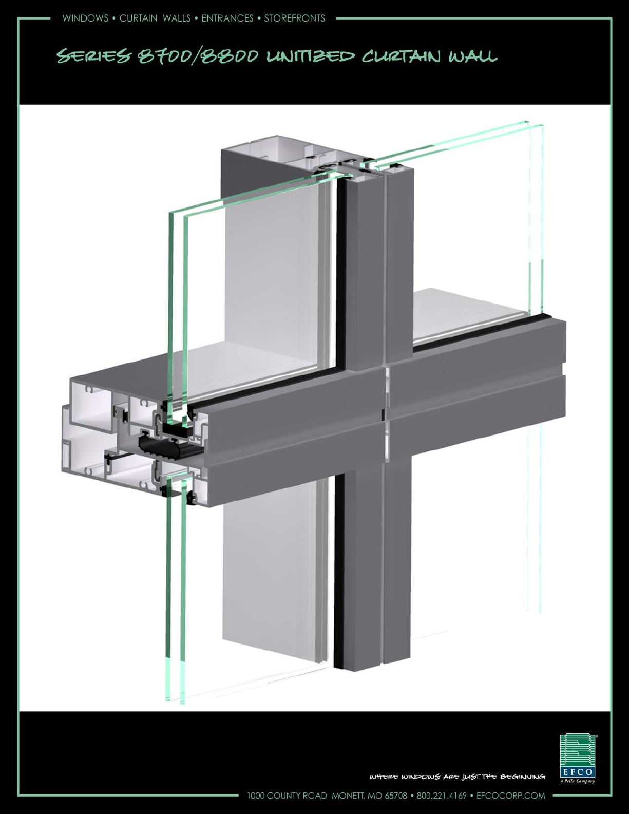
Series 8700 / 8800 Unitized Curtain Wall Assembly Instructions - Volume 6
Shadow Box and Back Panel Assembly Instructions Volume 6 of 6 - Sections 33 - 38
July 2011
PART NO. Y806
Page 2

EFCO 2009 Page 2
Series 8700 / 8800 Unitized Curtain Wall Assembly Instructions - Volume 6
Table of Contents
Volume 1 of 6
1. General Notes and Guidelines
2. Parts Identification
3. Frame Assembly
Volume 2 of 6
4. Unit Glazing Preparation : SSG and Captured
5. SSG Unit Glazing
6. Captured Unit Glazing
Series 8700 / 8800 Unitized Curtain Wall Assembly Instructions - Volume 6
Volume 3 of 6
7. Outside 90° Corner Frame Assembly
8. Inside 90° Corner Frame Assembly
9. Outside 90° Corner Unit Glazing Preparation : SSG and Captured
10. Inside 90° Corner Unit Glazing Preparation : SSG and Captured
Volume 4 of 6
11. Outside 90° Corner SSG Unit Glazing
12. Inside 90° Corner SSG Unit Glazing
13. Outside 90° Corner Captured Unit Glazing
14. Inside 90° Corner Captured Unit Glazing
Note: Assembly Instructions are provided as a supplement, and should be used in conjunction with
the approved shop drawings.
EFCO 2009 Page 2
Page 3

EFCO 2009 Page 3
Series 8700 / 8800 Unitized Curtain Wall Assembly Instructions - Volume 6
Table of Contents
Volume 5 of 6
SECTION PAGE
15. General Notes and Guidelines
16. Size Limitations
17. Standard Hardware Identification
18. Frame Assembly - Vent at Fixed Horizontal
19. Frame Assembly - Vent at Stack Sill
20. Unit Glazing Preparation - Vent at Fixed Horizontal
21. Unit Glazing Preparation - Vent at Stack Sill
22. SSG Vent Unit Glazing at Fixed Horizontal
23. SSG Vent Unit Glazing at Stack Sill
24. Captured Vent Unit Glazing at Fixed Sill
25. Captured Vent Unit Glazing at Stack Sill
26. Assembly and Glazing - SSG Vent at Fixed Horizontal
27. Assembly and Glazing - SSG Vent at Stack Sill
28. Assembly and Glazing - Captured Vent at Fixed Horizontal
29. Assembly and Glazing - Captured Vent at Stack Horizontal
30. Hardware Mounting On Unit Assembly
31. Hardware Mounting On Sash
32. Mounting Vent Assembly Into Unit Assembly
Series 8700 / 8800 Unitized Curtain Wall Assembly Instructions - Volume 6
Note: Assembly Instructions are provided as a supplement, and should be used in conjunction with
the approved shop drawings.
EFCO 2009 Page 3
Page 4

Series 8700 / 8800 Unitized Curtain Wall Assembly Instructions - Volume 6
Series 8700 / 8800 Unitized Curtain Wall Assembly Instructions - Volume 6
Table of Contents
Volume 6 of 6
SECTION PAGE
33. Shadow Box Assembly……………………………………………………………………
34. Shadow Box Installation………………………………………………………………….
35. Shadow Box Insulation Installation…………………………………………………….
36. Back Panel Installation……………………………………………………………………
37. Back Panel Insulation Installation………………………………………………………
38. Final Cleaning………………………………………………………………………………
5 - 7
8 - 9
10 - 11
12 - 13
14 - 15
16
Minimizing Condensation
Note: Please reference EFCO's "Understanding Condensation" brochure which can be obtained through your EFCO
representative.
Condensation will form on any surface when unfavorabl e cond itions (interior temperature and relative humidity and exterior
temperature) are present. When the formation of excessive condensation is a concern, it is highly recomm ended that a design
professional is utilized to perform an analysis of the shop drawings to recommend the best possible installation methods. Please
contact your EFCO representative for information on EFCO's Thermal Analysis Services.
Many current installation practices lead to an increase in the possibility of the formation of condensation. Though not all
inclusive, the list of examples below illustrates conditions under which condensation is lik ely to occur:
1. Bridging system thermal break with non-thermally broken metal flashing or lintels th at are exposed to the exterior
2. System exposure to cold air cavities
3. Interior relative humidity levels not maintained at recommended levels, see EFCO’s “Understanding
Condensation” brochure
4. Inadequate separation between system and surrounding condition at perimeter
5. Product combinations during the shop drawing stage that result in bridging thermal breaks
of one or all products involved
Note: Assembly Instructions are provided as a supplement, and should be used in conjunction with
the approved shop drawings.
EFCO 2011 Page 4
Page 5
Series 8700 / 8800 Unitized Curtain Wall Assembly Instructions - Volume 6
Section 33 - Shadow Box Assembly
1. Assemble the unit frame as shown in Volume 1 of Series 8700 / 8800 Unitized Curtain Wall Assembly Instructions, through “Section 3 - B. Unit Frame
Assembly”. For reduced handling for units with shadow boxes, assemble the unit frame with the interior side facing upward.
2. Clean the ends of the shadow box framing members where sealant will be applied with an approved solvent or cleaner.
3. Seal the ends of the shadow box frame members with sealant. See Figure 2.
4. Assembly the shadow box frame with (8) SLQ5 fasteners. Remove excess sealant from the outside areas of the frame corners.
5. Cap seal the fastener heads, seal inside the frame corners, and frame screw splines in the corners of the frame. Tool the sealant carefully to make water
tight. See Figures 3 and Figure 4.
Seal ends of shadow box
frames before assembly.
Shadow
Box Panel
Figure 1
Seal ends of shadow box
frames before assembly.
SLQ5
Fasteners
Figure 2 Figure 3 Figure 4
Cap seal
fastener heads.
Seal inside of
frame corners and
tool water tight.
SLQ5
Fasteners
EFCO 2009 Page 5
Page 6

Series 8700 / 8800 Unitized Curtain Wall Assembly Instructions - Volume 6
Section 33 - Shadow Box Assembly
6. Clean the surfaces of the shadow box frame where the tape and sealant will be applied with an approved solvent or cleaner.
7. Apply 1/4” x 1/4” glazing tape (WM86) to the shadow box frame. Remove the liner only from the side of the tape to be applied. See Figure 6.
8. Peel the remaining liner back about 1” from each end of the glazing tape to allow easy removal once the panel has been set.
9. Measure opposing corners and compare the dimensions to make sure the frame is square, and straig hten if required. Squareness of the frame is critical.
10. Set the panel onto the tape making sure the panel overhangs equally around all four edges (1/16” overhang). See Figures 7 and 8.
11. When the panel is in position, pull the remaining liner from the glazing tape and press the panel firmly into place.
Shadow
Box Frame
WM86
Glazing Tape
Figure 5
WM86
Glazing
Tape
Butt tape
ends square
at corners
Figure 6 Figure 8
Shadow
Box Panel
WM86
Glazing
Tape
Shadow
Box Frame
Shadow
Box Frame
Figure 7
1/16”
Shadow
Box Panel
EFCO 2009 Page 6
Page 7

Series 8700 / 8800 Unitized Curtain Wall Assembly Instructions - Volume 6
Section 33 - Shadow Box Assembly
12. Apply silicone sealant into the voids formed by the panel, tape, and shadow box frame being sure to fill the void completely.
13. Tool the sealant smooth and flush with the panel and the shadow box frame. The sealant joint should be continuous around all four sides of the shadow box
panel assembly. Allow proper cure time for the sealant joint before proceeding to the next step.
Apply silicone
sealant.
WM86
Glazing Tape
Apply silicone
sealant.
Shadow
Box Frame
Figure 9
Shadow
Box Frame
Figure 10
EFCO 2009 Page 7
Page 8

Series 8700 / 8800 Unitized Curtain Wall Assembly Instructions - Volume 6
Section 34 - Shadow Box Installation
1. For reduced handling, assemble the unit frame with the interior side facing upward. Use wood blocking set below the panel, clamped to the mullions on four
sides of the opening to provide the proper spacing for the shadow box. The number of wood blocks will very with the size of the panel to be applied.
2. Frames must be true and square. Prior to installing the shadow box panel, ensure the unit frame is square. Improperly squared units will cause significant
problems during the erection process. Check the frame for squareness by comp aring the difference between the two diagonal measurements of the frame
by measuring from corner to opposing corner for the two diagonal dimensions. The maximum out of square tolerance for a 10’-0” unit frame dimension is a
diagonal dimension difference of 1/16”.
3. Set the shadow box panel into the opening onto the wood blocking and apply 1/8” thick shims between the shadow box frame and the mullions at each
fastener location all around the shadow box panel. Place the shims at the horizontals where they won’t interfere with the sealant in step 4.
4. Apply sealant into the attachment holes in the shadow box frame adjacent to the horizontals filling the space around where the fastener will pass. See Figure
16 on page 9.
5. Attach the shadow box panel to the unit frame with STK3.
Set the shadow box panel
assembly into the opening on
wood blocking supports.
Use wood blocking
clamped to the mullions to
support the shadow box
The unit frame must be placed
with the interior side of the
framing facing upward for
shadow box installation.
Figure 11
Apply 1/8” shims and
attach with STK3
Apply 1/8” shims and
attach with STK3
Figure 12 Figure 13
EFCO 2009 Page 8
Page 9

Series 8700 / 8800 Unitized Curtain Wall Assembly Instructions - Volume 6
Section 34 - Shadow Box Installation
6. Clean the shadow box frame and mullion surfaces that will contact sealant with an approved solvent or cleaner.
7. Cap seal the tip of the fastener where it penetrates the vertical mullions with silicone sealant as shown below. Tool the sealant over the end of the fastener
and smooth it onto the mullion.
8. Apply backer rod and fill the void between the shadow box frame and the mullion with silicone sealant. The se al must be continuous and uninterrupted
around all four sides of the shadow box frame.
9. Tool the sealant into the joint, smoothing it around the four sides of the opening as shown below.
Shadow
Box Panel
Apply backer rod and fill the
void between the shadow
box frame and the mullion
with silicone sealant.
Figure 14
Vertical Mullion
Cap seal fastener
penetrations with
silicone sealant.
Apply backer rod and
sealant and tool the
sealant into the joint.
Figure 15 Figure 16
1/16”
Apply backer rod and
sealant and tool the
sealant into the joint.
Horizontal
Mullion
Apply sealant into
attachment holes in the
shadow box frame filling
the space around where
the fastener will pass
EFCO 2009 Page 9
Page 10

Series 8700 / 8800 Unitized Curtain Wall Assembly Instructions - Volume 6
Section 35 - Shadow Box Insulation Installation
1. Clean the panel and impaling pin surfaces that will contact sealant (or adhesive) with an approved solvent or cleaner.
2. Apply adhesive or sealant to the surface of the panel in a pattern per the manufacture’s recommendations. See Figure 17.
3. Apply impaling pins into the adhesive or sealant forcing the material through the holes in the base of the impaling pin. See Figure 19.
4. Tool the adhesive or sealant over the impaling pin base, and smooth it onto the panel. See Figure 20.
Impaling Pins
Apply sealant or adhesive in a
pattern as recommended by the
Adhesive
Shadow
Box Panel
impaling pin manufacturer.
Figure 17
Impaling Pin
Tool sealant
or adhesive
Impaling Pin
Apply pins into the
sealant or adhesive
Figure 18 Figure 20
Figure 19
EFCO 2009 Page 10
Page 11

Series 8700 / 8800 Unitized Curtain Wall Assembly Instructions - Volume 6
Section 35 - Shadow Box Insulation Installation
5. Cut the specified rigid insulation to size. The insulation should fit tightly into the framed opening. The edges of the insulation may be cut slightly angled to
assist with insertion into the opening.
6. Insert the insulation onto the impaling pins into the opening so that the insulation is flush with the back of the mullion.
7. Clean the surfaces of the mullion where the foil scrim tape will be applied with an approved solvent or cleaner.
8. Apply foil scrim tape to the four edges of the insulation and mullions to form an air tight seal. If the insulation is in more than one piece, tape the edges
together. See Figures 21 and 22.
9. Insert the self locking washers onto the impaling pins and force them down to the surface of the insulation to hold the insulation securely. Fold the exposed
end of the impaling down, flush with the insulation, and apply foil scrim tape to cover the pin and washer completely. See Figure 23.
Foil Scrim
Tape
Rigid insulation with scrim
Self Locking
Washers
reinforced foil facing on
interior surface.
Impaling Pins
Foil Scrim
Tape
Figure 22
Figure 21
Impaling Pins
Shadow
Box Panel
Foil Scrim
Tape
Self Locking
Washers
Impaling Pins
Figure 23
EFCO 2009 Page 11
Page 12

Series 8700 / 8800 Unitized Curtain Wall Assembly Instructions - Volume 6
Section 36 - Back Panel Installation
1. Rotate the assembled unit frame over so that the exterior side facing upward. Use wood blocking set below the panel, clamped to the mullions around the
opening to provide the proper spacing for the back panel. The number of wood blocks will very with the size of the back panel to be applied.
2. Frame must be true and square. Prior to installing the back panel, ensure the unit frame is square.
3. Set the back panel into the opening onto the wood blocking.
4. Attach the back panel to the unit frame with STK3 on all four sides of the panel.
5. Cap seal the fastener heads to the panel with silicone sealant.
Set the shadow box panel
into the opening on wood
blocking supports.
Attach the back panel to the unit frame with
STK3 on all four sides of the panel. Cap seal the
fastener heads to the panel with silicone sealant.
Use wood blocking
clamped to the mullions to
support the shadow box
Rotate the frame so that the
exterior side of the framing is
facing upward.
Figure 24
Figure 25
EFCO 2009 Page 12
Page 13

Series 8700 / 8800 Unitized Curtain Wall Assembly Instructions - Volume 6
Section 36 - Back Panel Installation
6. Using an approved solvent or cleaner, clean the surfaces to receive sealant of all oils and oth er contaminants.
7. The back panel has a raised lip that runs around the four sides of the panel. Apply sealant between this lip and the side of the mullion as shown below, filling
the void thoroughly. See Figure 28.
8. Tool the sealant into the joint smoothly, around all four sides continuously. See Figures 27 and 28.
9. Seal the corners of the back panel thoroughly with sealant. See Figure 27.
Seal continuously
with silicone sealant.
Seal the four
corners of the
Seal the four corners
of the back panel.
Cap seal all
fastener heads.
back panel.
Seal continuously on (4)
sides with silicone sealant.
Cap seal all
fastener heads.
Galvanized Steel
Back Panel
Figure 27
Seal continuously
with silicone sealant.
Cap seal all
fastener heads.
Galvanized Steel
Back Panel
Figure 26
Figure 28
EFCO 2009 Page 13
Page 14

Series 8700 / 8800 Unitized Curtain Wall Assembly Instructions - Volume 6
Section 37 - Back Panel Insulation Installation
1. Clean the panel and impaling pin surfaces that will contact sealant (or adhesive) with an approved solvent or cleaner.
2. Apply adhesive or sealant to the surface of the panel in a pattern per the manufacture’s recommendations. See Figure 29.
3. Apply impaling pins into the adhesive or sealant forcing the material through the holes in the base of the impaling pin. See Figure 31.
4. Tool the adhesive or sealant over the impaling pin base, and smooth it onto the panel. See Figure 32.
Apply sealant or adhesive in a
pattern as recommended by the
impaling pin manufacturer.
Impaling Pins
Adhesive
Galvanized Steel
Back Panel
Impaling Pin
Apply pins into the
sealant or adhesive
Figure 30
Figure 29
Impaling Pin
Figure 31
Tool sealant
or adhesive
Figure 32
EFCO 2009 Page 14
Page 15

Series 8700 / 8800 Unitized Curtain Wall Assembly Instructions - Volume 6
Section 37 - Back Panel Insulation Installation
5. Cut the specified rigid insulation to size. The insulation should fit tightly into the framed opening. The edges of the insulation may be cut slightly angled to
assist with insertion into the opening.
6. Insert the insulation onto the impaling pins into the opening so that the insulation is flush with the back of the mullion.
7. Clean the surfaces of the mullion where the foil scrim tape will be applied with an approved solvent or cleaner.
8. Apply foil scrim tape to the four edges of the insulation and mullions to form an air tight seal. If the insulation is in more than one piece, tape the edges
together. See Figures 33, 34 and 35.
9. Insert the self locking washers onto the impaling pins and force them down to the surface of the insulation to hold the insulation securely. Fold the exposed
end of the impaling down, flush with the insulation, and apply foil scrim tape to cover the pin and washer completely. See Figure 36.
Foil Scrim
Tape
Rigid insulation with scrim
Self Locking
Washers
Impaling Pins
reinforced foil facing on
interior surface.
Galvanized Steel
Back Panel
Figure 33
Foil Scrim
Tape
Figure 34
Impaling Pins
Self Locking
Washers
Figure 35
Foil Scrim
Tape
Impaling Pins
Foil Scrim
Tape
Self Locking
Washers
Impaling Pins
Figure 36
EFCO 2009 Page 15
Page 16

Series 8700 / 8800 Unitized Curtain Wall Assembly Instructions - Volume 6
Section 38 - Final Cleaning
1. Before proceeding with the glazing process, a thorough cleaning of the exposed areas of the shad ow box must be done.
2. Blow all debris out of the joints around the edges and exposed areas of the shadow box. Any metal shavings or dirt must be removed from the opening.
After the unit is glazed, during handling, debris could dislodge and become visible through the glass unless proper cleaning is performed.
3. Use isopropyl alcohol to clean the exposed finished surfaces of all smudges, finger prints, and sealant. Once the unit is glazed, these areas will be
inaccessible, so a thorough cleaning is essential.
4. Proceed to Volume 2, Section 4 “Unit Glazing Preparation”.
Thoroughly blow all debris
out of the joints around the
edges of the shadow box.
Use isopropyl alcohol to clean the
shadow box exposed finished surfaces of
all smudges, finger prints, and sealant.
Figure 37
EFCO 2009 Page 16
 Loading...