

Page 1
EFCO 2012 Page
Series 8700 / 8800 Unitized Curtain Wall Assembly Instructions - Volume 2
Flat Wall Assembly Instructions Volume 2 of 6 - Sections 4 - 6
April 2012
PART NO. Y802
Page 2

EFCO 2009 Page 2
Series 8700 / 8800 Unitized Curtain Wall Assembly Instructions - Volume 2
Table of Contents
Volume 1 of 6
1. General Notes and Guidelines
2. Parts Identification
3. Frame Assembly
Volume 2 of 6
SECTION PAGE
Series 8700 / 8800 Unitized Curtain Wall Assembly Instructions - Volume 2
4. Unit Glazing Preparation : SSG and Captured………….........................................
5. SSG Unit Glazing
A. Temporary Glazing Locators…………………………......................................
B. Setting and Caulking Glazing ……………………………………………………
C. Adapter Installation………………….……………………………………………..
D. Weather Seal Application…………………………………………………………
E. Jamb Mullion Installation………………………………...……………………….
6. Captured Unit Glazing
A. Temporary Glazing Locators……………………………………………………..
B. Setting and Caulking Glazing ……………………………………………………
C. Adapter and Cover Installation……….………………………………………….
D. Joint Plug Installation………………….…………………………………………..
E. Jamb Mullion Installation………………………………...……………………….
6 - 7
8
9 - 10
11 - 15
16 - 17
18 - 19
20
21 - 22
23 -30
31 - 32
33 - 34
Note: Assembly Instructions are provided as a supplement, and should be used in conjunction with
the approved shop drawings.
EFCO 2009 Page 2
Page 3

EFCO 2009 Page 3
Series 8700 / 8800 Unitized Curtain Wall Assembly Instructions - Volume 2
Table of Contents
Volume 3 of 6
7. Outside 90° Corner Frame Assembly
8. Inside 90° Corner Frame Assembly
9. Outside 90° Corner Unit Glazing Preparation : SSG and Captured
10. Inside 90° Corner Unit Glazing Preparation : SSG and Captured
Series 8700 / 8800 Unitized Curtain Wall Assembly Instructions - Volume 2
Volume 4 of 6
11. Outside 90° Corner SSG Unit Glazing
12. Inside 90° Corner SSG Unit Glazing
13. Outside 90° Corner Captured Unit Glazing
14. Inside 90° Corner Captured Unit Glazing
Note: Assembly Instructions are provided as a supplement, and should be used in conjunction with
the approved shop drawings.
EFCO 2009 Page 3
Page 4

EFCO 2009 Page 4
Series 8700 / 8800 Unitized Curtain Wall Assembly Instructions - Volume 2
Table of Contents
Volume 5 of 6
15. General Notes and Guidelines
16. Size Limitations
17. Standard Hardware Identification
18. Frame Assembly - Vent at Fixed Horizontal
19. Frame Assembly - Vent at Stack Sill
20. Unit Glazing Preparation - Vent at Fixed Horizontal
21. Unit Glazing Preparation - Vent at Stack Sill
22. SSG Vent Unit Glazing at Fixed Horizontal
23. SSG Vent Unit Glazing at Stack Sill
24. Captured Vent Unit Glazing at Fixed Sill
25. Captured Vent Unit Glazing at Stack Sill
26. Assembly and Glazing - SSG Vent at Fixed Horizontal
27. Assembly and Glazing - SSG Vent at Stack Sill
28. Assembly and Glazing - Captured Vent at Fixed Horizontal
29. Assembly and Glazing - Captured Vent at Stack Horizontal
30. Hardware Mounting On Unit Assembly
31. Hardware Mounting On Sash
32. Mounting Vent Assembly Into Unit Assembly
Series 8700 / 8800 Unitized Curtain Wall Assembly Instructions - Volume 2
Note: Assembly Instructions are provided as a supplement, and should be used in conjunction with
the approved shop drawings.
EFCO 2009 Page 4
Page 5

Series 8700 / 8800 Unitized Curtain Wall Assembly Instructions - Volume 2
Series 8700 / 8800 Unitized Curtain Wall Assembly Instructions - Volume 2
Table of Contents
Volume 6 of 6
33. Shadow Box Assembly
34. Shadow Box Installation
35. Shadow Box Insulation Installation
36. Back Panel Installation
37. Back Panel Insulation Installation
38. Final Cleaning
Minimizing Condensation
Note: Please reference EFCO's "Understanding Condensation" brochure which can be obtained through your EFCO
representative.
Condensation will form on any surface when unfavorable conditions (interior temperature and relative humidity and
exterior temperature) are present. When the formation of excessive condensation is a concern, it is highly recommend ed that a
design professional is utilized to perform an analysis of the shop drawings to recommend the best possible installation methods.
Please contact your EFCO representative for information on EFCO's Thermal Analysis Services.
Many current installation practices lead to an increase in the possibility of the formation of condensation. Though not all
inclusive, the list of examples below illustrates conditions under which condensation is lik ely to occur:
1. Bridging system thermal break with non-thermally broken metal flashing or lintels th at are exposed to the exterior
2. System exposure to cold air cavities
3. Interior relative humidity levels not maintained at recommended levels, see EFCO’s “Understanding
Condensation” brochure
4. Inadequate separation between system and surrounding condition at perimeter
5. Product combinations during the shop drawing stage that result in bridging thermal breaks
of one or all products involved
Note: Assembly Instructions are provided as a supplement, and should be used in conjunction with
EFCO 2009 Page 5
the approved shop drawings.
EFCO 2011 Page 5
Page 6
Series 8700 / 8800 Unitized Curtain Wall Assembly Instructions - Volume 2
Section 4 - Unit Glazing Preparation : SSG and Captured
1. Using an approved solvent or cleaner, clean the surfaces of the mullions to receive the WC18 spacer gasket and sealant of all oils and other
contaminants. The sealant manufacturer’s preparation and application instructions should be followed exactly.
2. If sealant primer is required, apply it per the primer/sealant manufacturer’s instructions. See the note in Figure 1 below.
3. Frames must be true and square before being structurally glazed. Improperly squared units will ca use significant problems during the erection process.
Check the frame for squareness by comparing the difference between the two diagonal measurements of the frame by measuring from corner to opposing
corner for the two diagonal dimensions. The maximum out of square tolerance for a 10’-0” unit frame dimension is a dia gonal dimens ion difference of 1/16”.
If frames are found to exceed this tolerance limit, the frame must be squared using bar clamps. Additionally, individual D.L.O. squareness should be checked
using the procedure above. If bar clamps or other methods are used to square the frame, the device may need to remain on the frame until the sealant is
cured (8 hours minimum).
4. Inspect the I.G. units for the frame. Any excessive sealant or irregularities in the dual seal or glass edge should be cleaned and trimmed. Check for glass
damage, particularly along the glass edges and discard any unacceptable units. At this time, the secondary sealant joints of the insulated glass units should
be checked for proper size. The approved shop drawings will indicate the required secondary sealant joint size on the general information page. Check the
alignment of each pane making up the I.G. unit to ensure they are within acceptable limits. The I.G. unit overall dimensions should be verified for proper size.
Note: After cleaning and priming the glazing substrates
(priming when required), the glazing must be set
immediately and the structural silicone applied. The time
between cleaning, priming and applying the structural
silicone should be less than two hours. Otherwise, the
substrates may become contaminated, and the primer will
oxidize. If units have been prepared for glazing at the end
of the day, and sealant has not yet been applied, cleaning
and priming must be redone prior to glazing the next day.
Apply the WC18 spacer
gasket to the mullions.
Figure 1
EFCO 2009 Page 6
Page 7

Series 8700 / 8800 Unitized Curtain Wall Assembly Instructions - Volume 2
Section 4 - Unit Glazing Preparation : SSG and Captured
5. Apply the WC18 spacer gasket to the mullions as shown below and on page 6. The gasket will run through vertically, and butt together at the corners (see
Figure 4). “Crowd” in extra gasket, (approximately 10% extra) where it runs between the vertical gaskets to ensure a snug butt joint at the corners. It is
important that there are no gaps in the gaskets where they meet in the corners. Note that the gasket is not symmetrical, and must be installed so that it is
flush with the side of the mullions (see Figure 2).
6. A 3/8” backer rod should be applied into the isolator reglet to prevent sealant from getting into the reglet. Remove the backer rod immediately after the
sealant is applied, and before the sealant begins to cure and skin over (See Figure 3).
Insert a 3/8” backer rod into isolator reglets to
keep free of sealant. Remove the backer rod
immediately, before sealant begins to skin over.
Apply WC18 gaskets
flush with the side of
the mullions.
Isolator
Reglet
Figure 2
JAMB
Butt gaskets at
D.L.O. corners.
SILL
Butt gaskets at
D.L.O. corners.
JAMB
INTERMEDIATE
Figure 4
Figure 3
Butt gaskets at
D.L.O. corners.
JAMB
HEAD
EFCO 2009 Page 7
Page 8
Series 8700 / 8800 Unitized Curtain Wall Assembly Instructions - Volume 2
Section 5 - SSG Unit Glazing : A. Temporary Glazing Locators
1. In order to properly
locate the glazing,
temporary adapters must
be used at the bottom
edge of the glazing.
Apply two temporary
glazing locators (KV01,
KV02) at approximate
quarter points at the sill
and intermediate
horizontal locations as
shown in Figures 5, 6,
and 7.
2. Using an approved
solvent or cleaner,
thoroughly clean the
edges of the glazing
that will contact the
structural silicone and
spacer of all oils and
other contaminants.
Once the glass has been
cleaned, it should be
handled with gloves to
avoid contaminating the
edges that come into
contact with the
structural silicone
glazing joint.
Temporary Glazing
Locators
Figure 5
17H6
L142
HS32
KV02
Figure 6 - SSG Intermediate Horizontal
HS32 17B7
L142
EFCO 2009 Page 8
Figure 7 - SSG Stack Sill
KV01
Page 9
Series 8700 / 8800 Unitized Curtain Wall Assembly Instructions - Volume 2
Section 5 - SSG Unit Glazing: B. Setting and Caulking Glazing
3. Set the glazing on the silicone spacer gaskets positioned as shown below. The edge of the gla zing i s flush with the edge of the vertical mullion. Refer to
Figure 9 below. Ensure the glazing is pressed firmly onto the setting blocks of the temporary retainers as shown in Figures 10 and 11.
4. Align the glazing as shown and noted. Ensure the glazing is positioned with the exterior side out, and the bottom of the glazing to the setting blocks. Care
should be exercised to avoid shifting or rolling the spacer gaskets when adjusting the position of the glass.
5. After the glass is aligned and in the final position, remove the setting blocks and temporary glazing locators.
6. Apply structural silicone sealant into the void between the glass and mullion per the sealant manufacturer’s application instructions. A 3/8” backer rod should
be applied into the isolator reglet to prevent sealant from getting into the reglet (see Figure 9). See additional notes, and Figures 12, 13, and 14 on page 10
for sealant application and tooling instructions.
7. Immediately tool the sealant joint after application to insure the joint is completely filled with sealant on all four sides of each piece of glazing. Make sure no
air bubbles or voids are present in the sealant joint.
8. Remove the backer rod, before the sealant begins to cure and skin over.
Note:
Only silicone sealants
which have been
developed and tested
specifically for structural
glazing applications
should be used for
glazing purposes.
Apply structural silicone
sealant into the void and
tool the joint to fill the
void completely.
Insert a 3/8” backer rod
into isolator reglet to keep
free of sealant. Remove the
backer rod immediately
before sealant begins to
skin over.
Glass is flush with
edge of mullion.
SILL
Figure 10
Figure 9
JAMB
Figure 11
JAMB
Figure 8
KV01
HEAD
Set glazing onto the silicone
spacer gaskets and against
the setting blocks at the
temporary glazing locators.
KV02
EFCO 2009 Page 9
Figure 9
Figure 10 Figure 11
Page 10
Series 8700 / 8800 Unitized Curtain Wall Assembly Instructions - Volume 2
Section 5 - SSG Unit Glazing: B. Setting and Caulking Glazing
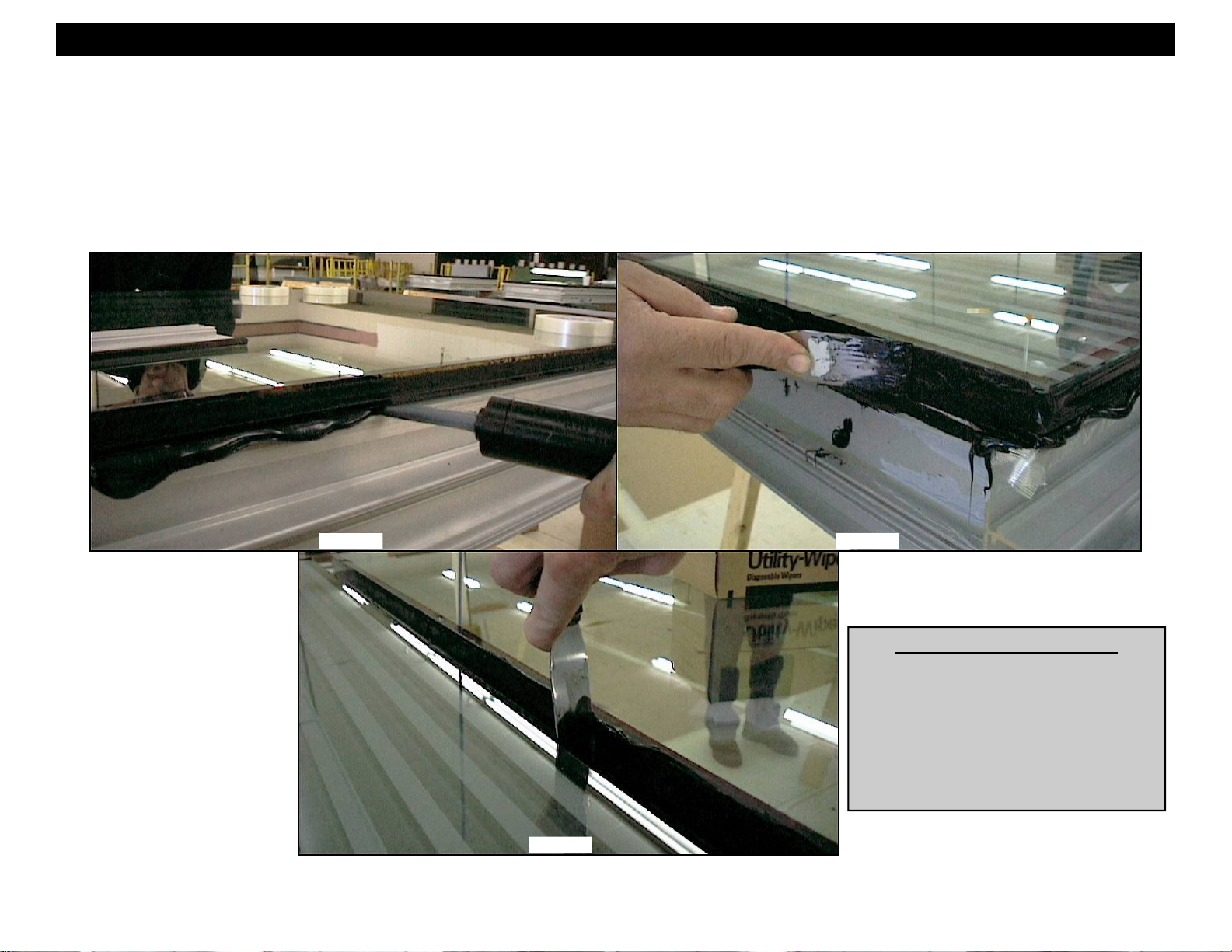
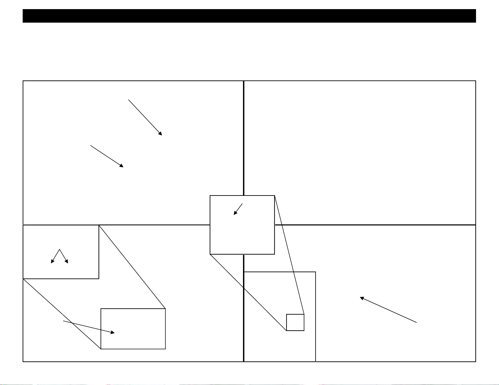
9. Follow the sealant manufacturer’s instructions for application equipment preparation and qu ality control procedures.
10. Apply sealant and tool the frames as required per the sealant manufacturer’s application instructions in the Structural Sealant Glazing Manual. Care should
be taken to insure that the sealant void at the glass edge is completely filled. The sealant gun operator should visually confirm that this void is being filled at
the time of application (See figures 12, 13 and 14). Clean up any excess sealant that may get into the gasket reglets or any other areas that sealant would
be undesirable.
11. Frames should not be moved until the sealant has cured and per the sealant manufacturer’s recommendations.
Figure 12
Note:
Only silicone sealants
which have been
developed and tested
specifically for structural
glazing applications
should be used for
glazing purposes.
Figure 13
GLASS SIZE FORMULAS
Per Side Add Dimensions
Standard Mullions - D.L.O. + 13/16”
Inside Corner Mullion - D.L.O. + 13/16”
Outside Corner Mullion - D.L.O. + 1 7/16”
Note: Job specific corner conditions may
vary glass bite. Refer to final approved
shop drawings.
Figure 14
EFCO 2012 Page 10
Page 11
Series 8700 / 8800 Unitized Curtain Wall Assembly Instructions - Volume 2
Section 5 - SSG Unit Glazing: C. Adapter Installation
1. After sealant has cured, cut L142 to length with vinyl cutters. Apply the thermal isolator L142 into the verticals and horizontals. L142 is supplied in 1 0’-0”
lengths. L142 may be used in several pieces to accommodate the required length. By butting multiple pieces together, waste will be avoided and the desired
length can be obtained.
2. Apply the preset thermal isolator (WC16) to the head, running the gasket continuously between the vertical mullions (See Figure 18).
3. Figure 17 shows the various isolators and gaskets used in this section.
L142 Thermal
Isolator Clip
L142
Vinyl Cutters
Figure 15
WC16
L142
WC19
WC16
LC23
WC17
Figure 17
L142 Thermal
Isolator Clip
Figure 16
Figure 18
WC16 Isolator
Gasket
EFCO 2009 Page 11
Page 12

Series 8700 / 8800 Unitized Curtain Wall Assembly Instructions - Volume 2
Section 5 - SSG Unit Glazing: C. Adapter Installation
4. Apply 17B7 SSG glazing adapter to the stack sill. Final adjustment of the 17B7 will be made after the vertical glazing adapters are applied.
5. Slide the WC17 horizontal stack joint rain screen gasket into position as shown in Figures 20, 21, and 22. WC17 runs the same length as 17B7 and is applied
flush with each end of 17B7.
6. Insert HS32 setting blocks between the stack sill glazing adapter and the glass at quarter points, or as directed per the final approved shop drawings. Light
prying pressure may need to be applied to the glazing adapter to insert the setting blocks into place. Use care so that the glazing is not damaged.
HS32 Setting
Blocks
17B7 SSG Stack Sill
Glazing Adapter
Figure 19
Figure 20
Slide WC17 gasket
into 17B7
L142 stops 3/4” short of
the end of the mullion at
this location.
Figure 22
WC17 Horizontal
Stack Joint Rain
Screen Gasket
Figure 21
HS32
L142
WC17
17B7
EFCO 2009 Page 12
Page 13

Series 8700 / 8800 Unitized Curtain Wall Assembly Instructions - Volume 2
Section 5 - SSG Unit Glazing: C. Adapter Installation
7. Clean the sealant contact surfaces of the mullion with an approved solvent or cleaner and apply a heavy bead of sealant to the tops of the vertical
mullions as shown in Figure 23.
8. Clean the sealant contact surfaces of the gutter with an approved solvent or cleaner. Apply sealant to the underside of the gutter where it will contact
the ends of the vertical with a bed of sealant. This will ensure that all voids are filled and good sealant contact is achieved once the gutter is applied t o the
frame. Install the SSG gutter to the frame at the head horizontal and secure with SPZ1. See Figure 24. It is critical that the sealants applied to the
gutter and mullion are thoroughly tooled and blended together to make watertight. See Figure 25.
9. Slide in WC19 gasket and LC23 spacer into the gutter. LC23 spacer runs continuously and is flush with the ends of the gutter. WC19 runs continuously, and
is cut 3” longer than the gutter (1 1/2” on each end). See figure 26.
Note! Critical seal!
The sealant must be
thoroughly tooled and
blended over the adjacent
surfaces all around the
sealant contact areas
shown in Figure 23. This
seal occurs at the top of
each vertical mullion.
Apply a h e avy
bead of sealant to
the tops of the
verticals.
Figure 25
Slide in WC19 Horizontal
Stack Joint Seal Gasket.
SPZ1
Slide in LC23 Horizontal
Stack Joint Spacer Gasket.
Figure 26
17B6 SSG Horizontal
Stack Gutter
Figure 23
SSG Gutter
SPZ1
SPZ1
Figure 24
EFCO 2009 Page 13
Page 14

Series 8700 / 8800 Unitized Curtain Wall Assembly Instructions - Volume 2
Section 5 - SSG Unit Glazing: C. Adapter Installation
10. Slide WC20 bulb gasket into 17A6 SSG vertical fin bar. Exercise care to avoid stretching the gasket during installation. Let the bulb gasket run approximately
1/4” longer than 17A6. The bulb gasket must be installed prior to applying 17A6.
11. Crimp the bulb in place to prevent slippage during unit installation. Crimp at each end of the adapter, and 24” on center.
12. Roll the 17A6 SSG vertical fin bar into the isolator in each vertical mullion of the assembled unit (See Figures 27 and 28). Crowd the bulb gasket so it is flush
with each end of the fin bar during fin bar installation. The fin bar runs between the gutter and the stack sill glazing adapter with approximately 1/8” gaps at
each end for sealant continuity.
13. Adjust the 17B7 stack sill adapter so that it is flush with the 17A6 vertical fin bar on each end as shown in Figure 29.
17A6 SSG Vertical Fin Bar
17B7 SSG Stack Sill
Glazing Adapter
WC20
Insert 17A6 into the isolator
and roll into position.
WC20
Figure 29
1/8” gap for sealant
continuity.
Figure 27
Figure 28 Figure 30
EFCO 2009 Page 14
Page 15

Series 8700 / 8800 Unitized Curtain Wall Assembly Instructions - Volume 2
Section 5 - SSG Unit Glazing: C. Adapter Installation
14. Using an approved solvent or cleaner, clean the surfaces of the mullions at the intersection of the intermediate horizontal and vertical.
15. Apply a heavy bead of sealant at the intersection of the intermediate horizontal and vertical (See Figure 32). The sealant should run between the structural
seals of the adjacent lites and extend from the edge of the vertical over to below where the intermediate horizo ntal adapter will be set.
16. Roll the 17H6 SSG glazing adapter into the isolator at the horizontal as shown in Figure 33. This must be done immediately after step 14 and 15 above,
before the sealant begins to cure. The adapter should be setting in sealant at the ends while leaving the notched areas free of sealant. The notch areas at
the ends are to be left open and sealant free for use as a weep system for the horizontals.
17. Insert HS32 setting blocks between the glazing adapter and the glass at quarter points, or as directed per the final approved shop drawings. Light prying
pressure may need to be applied to the glazing adapter to insert the setting blocks into place.
HS32 Setting
Figure 31
Apply a heavy bead of sealant at
the intersection of the intermediate
horizontal and vertical.
Figure 32 Figure 33
Block
17H6 SSG
Glazing Adapter
EFCO 2009 Page 15
Page 16

Series 8700 / 8800 Unitized Curtain Wall Assembly Instructions - Volume 2
Section 5 - SSG Unit Glazing: D. Weather Seal Application
1. Using an approved solvent or cleaner, clean the sealant contact surfaces of the gla zin g and adapters of all oils and other contaminants.
2. If sealant primer is required, apply it per the primer/sealant manufacturer’s instructions.
3. Insert 3/8” diameter backer rod between the glazing and adapters around all four corners of each lite of glazing. Refer to Figure 38 on the following page for
more information.
4. Apply sealant into the void between the adapters and glazing. If the sealant is properly and carefully applied, masking tape is not necessary on the adjacent
surfaces.
5. Before the sealant begins to cure or skin over, tool the sealant into the joints smoothly, taking care to smooth and blend the sealant in the corners and
intermediate intersections as shown below. Seen in section view, the sealant should have an hourglass shape and maintain a 2:1 width to depth ratio as
shown in Figure 38 on page 17. Remove any excess sealant from the surrounding surfaces before the sealant begins to cure.
Figure 34
Sealant
Continuity Joint
Sealant
Continuity Joint
Sealant
Continuity Joint
Figure 35 Figure 36 Figure 37
EFCO 2009 Page 16
Page 17

Series 8700 / 8800 Unitized Curtain Wall Assembly Instructions - Volume 2
Section 5 - SSG Unit Glazing: D. Weather Seal Application
6. Ensure the sealant continuity joints between the adapters are properly filled with sealant and tooled smoothly for best aesthetics. Refer to Figures 35, 36,
and 37 on page 16 for detailed views of the weather seals and sealant continuity joints.
7. Allow units to sit undisturbed until the sealant is cured and per the sealant manufacturer’s recommendations.
8. If units are being stored or shipped on their sides, prevent any pressure from being applied to the adapters, or the weather seals will be damaged.
Glazing Infill
Silicone Sealant
Weather Seal
3/8” Backer Rod
Stack Sill
Assembly
Figure 38
Vertical Mullion
Assembly
EFCO 2009 Page 17
Page 18

Series 8700 / 8800 Unitized Curtain Wall Assembly Instructions - Volume 2
Section 5 - SSG Unit Glazing: E. Jamb Mullion Installation
1. Clean the sealant contact surfaces on the underside of the gutter (Figure 40) and the top of the jamb (Figure 41) using an approved solvent or
cleaner. Apply a heavy bed of sealant to the underside of the gutter and onto the mullion stack leg of the assembled mullion as shown in Figure 40.
2. Apply a heavy bead of sealant to the jamb as shown in Figure 41.
3. Tilting the jamb at an angle as shown in Figures 41 and 42, mate the jamb and unit mullions beginning at the gutter end and rotating the jamb into place as
shown. Use clamps to snap together the jamb to the unit mullion. Light tapping with a glazing hammer will aid in snapping the mullions.
4. Secure the jamb mullion to the unit with SFQ5 fasteners into the 8806 spacers. Tool the sealant smooth as shown in Figure 43.
HEAD
8806 Spacer
(See Volume 1, Page 31).
SILL
SFQ5
8806 Spacer
(See Volume 1, Page 31).
Figure 39
Apply a heavy bead
of sealant to the end
of the jamb.
Insert the top of the
mullion first, mating it
with the unit mullion
Apply the “Z” clip to the vertical mullion
(See Volume 1, Pages 29 and 30.
Slide WC21 gasket into the jamb
mullion (See Volume 1, Page 26.
Figure 42 Figure 41 Figure 43
Apply a heavy bed of sealant
on the underside of the gutter
and onto the mullion stack leg.
8806
Figure 40
Tool sealant smooth,
blending it into the
adjacent surfaces.
EFCO 2009 Page 18
Page 19

Series 8700 / 8800 Unitized Curtain Wall Assembly Instructions - Volume 2
Section 5 - SSG Unit Glazing: E. Jamb Mullion Installation
5. Clean the end dam of all oils and contaminants and apply a bed of sealant to the jamb corresponding to where the end dam will be applied.
6. Before the sealant begins to cure or skin over from steps 1 and 2, apply the gutter end dam flush with the underside and notched face of the gutter with (2)
STT6 screws.
7. Apply a heavy bead of sealant where the top of the gutter and the inside of the end dam meet (See figure 46). Tool all of the sealant around the end dam
smooth.
8. Insert L142 isolator into the jamb mullion and roll on the 17A9 jamb mullion cover (See Figures 47 and 48). Center 17A9 between the gutter and the stack sill
glazing adapter with equal spacing on each end.
9. Drive in WVD1 wedge gasket between 17A9 and the jamb mullion (See Figures 47 and 48).
Apply a bed of sealant
for the end dam
End Dam
STT6
WVD1 Wedge
Gaskets
Figure 44
17A9 Jamb
Mullion Cover
Apply the end dam
flush with notch.
Figure 45
Tool sealant smooth,
blending it into the
adjacent surfaces.
Figure 46
17A9 Jamb
L142
Mullion Cover
Figure 49 Figure 48 Figure 47
EFCO 2009 Page 19
Page 20

Series 8700 / 8800 Unitized Curtain Wall Assembly Instructions - Volume 2
Section 6 - Captured Unit Glazing : A. Temporary Glazing Locators
1. In order to properly
locate the glazing,
temporary adapters must
be used at the bottom
edge of the glazing.
Apply two temporary
glazing locators KV03
AND KV04 at
approximate quarter
points of the sill and
intermediate horizontal
locations as shown in
Figures 50, 51, and 52.
2. Using an approved
solvent or cleaner,
thoroughly clean the
edges of the glazing
that will contact the
structural silicone and
spacer of all oils and
other contaminants.
Once the glass has been
cleaned, it should be
handled with gloves to
avoid contaminating the
edges that come into
contact with the
structural silicone
glazing joint.
Temporary Glazing
Locators
Figure 50
17B9
L142
Figure 51 - Captured Intermediate Horizontal
(2) HS31
KV03
17B5
(2) HS31
L142
Figure 52 - Captured Stack Sill
KV04
EFCO 2009 Page 20
Page 21

Series 8700 / 8800 Unitized Curtain Wall Assembly Instructions - Volume 2
Section 6 - Captured Unit Glazing : B. Setting and Caulking Glazing
3. Set the glazing on the silicone spacer gaskets positioned as shown below. The edge of the gla zing i s flush with the edge of the vertical mullion. Refer to
Figure 54 below. Ensure the glazing is pressed firmly onto the setting blocks of the temporary retainers as shown in Figures 55 and 56.
4. Align the glazing as shown and noted. Ensure the glazing is positioned with the exterior side out, and the bottom of the glazing to the setting blocks. Care
should be exercised to avoid shifting or rolling the spacer gaskets when adjusting the position of the glass.
5. After the glass is aligned and in the final position, remove the setting blocks and temporary glazing locators.
6. Apply structural silicone sealant into the void between the glass and mullion per the sealant manufacturer’s application instructions. A 3/8” backer rod should
be applied into the isolator reglet to prevent sealant from getting into the reglet (see Figure 54). See additional notes, and Figures 57, 58, and 59 on page 22
for sealant application and tooling instructions.
7. Immediately tool the sealant joint after application to insure the joint is completely filled with sealant on all four sides of each piece of glazing. Make sure no
air bubbles or voids are present in the sealant joint.
8. Remove the backer rod, before the sealant begins to cure and skin over.
JAMB
Note:
Only silicone sealants
which have been
developed and tested
specifically for structural
glazing applications
should be used for
glazing purposes.
SILL
Figure 55
Figure 54
Figure 56
JAMB
Figure 53
HEAD
Set glazing onto the silicone
spacer gaskets and against
the setting blocks at the
temporary glazing locators.
Apply structural silicone
sealant into the void and
tool the joint to fill the
void completely.
Insert a 3/8” backer rod
into isolator reglet to keep
free of sealant. Remove the
backer rod immediately
before sealant begins to
skin over.
Glass is flush with
edge of mullion.
KV04
L142
Figure 54 Figure 55 Figure 56
KV03
L142
EFCO 2009 Page 21
Page 22

Series 8700 / 8800 Unitized Curtain Wall Assembly Instructions - Volume 2
Section 6 - Captured Unit Glazing : B. Setting and Caulking Glazing
9. Follow the sealant manufacturer’s instructions for application equipment preparation and qu ality control procedures.
10. Apply sealant and tool the frames as required per the sealant manufacturer’s application instructions in the Structural Sealant Glazing Manual. Care should
be taken to insure that the sealant void at the glass edge is completely filled. The sealant gun operator should visually confirm that this void is being filled at
the time of application (See figures 57, 58 and 59). Clean up any excess sealant that may get into the gasket reglets or any other areas that sealant would
be undesirable.
11. Frames should not be moved until the sealant has cured and per the sealant manufacturer’s recommendations.
Figure 57
Note:
Only silicone sealants
which have been
developed and tested
specifically for structural
glazing applications
should be used for
glazing purposes.
Figure 59
Figure 58
GLASS SIZE FORMULAS
Per Side Add Dimensions
Standard Mullions - D.L.O. + 13/16”
Inside Corner Mullion - D.L.O. + 13/16”
Outside Corner Mullion - D.L.O. + 7/8”
EFCO 2009 Page 22
Page 23

Series 8700 / 8800 Unitized Curtain Wall Assembly Instructions - Volume 2
Section 6 - Captured Unit Glazing: C. Adapter and Cover Installation
1. Cut L142 to length with vinyl cutters. Apply the thermal isolator L142 into the verticals and horizontals. L142 is supplied in 10’-0” lengths. L142 may be used
in several pieces to accommodate the required length. By butting multiple pieces together, waste will be avoided and the desired length can be obtained.
2. Apply the preset thermal isolator (WC16) to the head running the gasket continuously between the vertical mullions (See Figure 63).
3. Figure 62 shows the various isolators and gaskets used in this section.
L142 Thermal
Isolator Clip
L142
Vinyl Cutters
Figure 60
WC16
L142
WC19
WC16
LC23
WC17
Figure 62
L142 Thermal
Isolator Clip
Figure 61
Figure 63
WC16
Isolator
Gasket
EFCO 2009 Page 23
Page 24

Series 8700 / 8800 Unitized Curtain Wall Assembly Instructions - Volume 2
Section 6 - Captured Unit Glazing: C. Adapter and Cover Installation
4. Apply 17B5 Captured glazing adapter to the stack sill. Final adjustment of the 17B5 will be made after the vertical glazing adapters are applied.
5. Slide the WC17 horizontal stack joint rain screen gasket into position as shown in Figures 65, 66, and 67. WC17 runs the same length as 17B5 and is applied
flush with each end of 17B5.
6. Insert HS31 setting blocks (2 at each location) between the stack sill glazing adapter and the glass at quarter points, or as directed per the final approved
shop drawings. Light prying pressure may need to be applied to the glazing adapter to insert the setting blocks into place.
(4) HS31 Setting
Blocks
WC17 Horizontal
Stack Joint Rain
Screen Gasket
17B5 Captured Stack
Sill Glazing Adapter
L142 stops 3/4” short of
the end of the mullion at
this location.
Figure 64
Figure 65
Slide WC17 gasket
into 17B5
Figure 67
Figure 66
WC17
HS31
L142
17B5
EFCO 2009 Page 24
Page 25

Series 8700 / 8800 Unitized Curtain Wall Assembly Instructions - Volume 2
Section 6 - Captured Unit Glazing: C. Adapter and Cover Installation
7. Clean the sealant contact surfaces of the mullion with an approved solvent or cleaner and apply a heavy bead of sealant to the tops of the vertical
mullions as shown in Figure 68.
8. Clean the sealant contact surfaces of the gutter with an approved solvent or cleaner. Apply sealant to the underside of the gutter where it will contact
the ends of the vertical with a bed of sealant. This will ensure that all voids are filled and good sealant contact is achieved once the gutter is applied t o the
frame. Install the SSG gutter to the frame at the head horizontal and secure with SPZ1. See Figure 69. It is critical that the sealants applied to the
gutter and mullion are thoroughly tooled and blended together to make watertight. See Figure 70.
9. Slide in WC19 gasket and LC23 spacer into the gutter. LC23 spacer runs continuously and is flush with the ends of the gutter. WC19 runs continuously, and
is cut 3” longer than the gutter (1 1/2” on each end). See figure 71.
Note! Critical seal!
The sealant must be
thoroughly tooled and
blended over the adjacent
surfaces all around the
sealant contact areas
shown in Figure 68. This
seal occurs at the top of
each vertical mullion.
Apply a h e avy
bead of sealant to
the tops of the
verticals.
Figure 70
WC19 Horizontal Stack
Joint Seal Gasket
SPZ1
LC23 Horizontal Stack Joint
Spacer Gasket
Figure 71
Horizontal Stack Gutter
17B1 Captured
Figure 68
Captured Gutter
SPZ1
SPZ1
Figure 69
EFCO 2009 Page 25
Page 26

Series 8700 / 8800 Unitized Curtain Wall Assembly Instructions - Volume 2
Section 6 - Captured Unit Glazing: C. Adapter and Cover Installation
10. Insert 17K1 glazing retainer into 17B5 and roll into position (See Figure 73). Insert 17K0 glazing retainer into 17B1 and roll into position (See Figure 74). The
glazing retainers will be flush with the ends of the adapters.
11. Drive in WC22 wedge gasket between 17K0, 17K1 and the glazing infill as shown in Figures 75 and 76. Start in the center, then move to the ends crowding
in as much gasket as possible (approximately 4% to 5% extra). Do not stretch the gasket during application. The WC22 should be trimmed to the same
length as 17K0 and 17K1.
WC22
17K0
17B1
WC22
17K1
17B5
Figure 72
17K1 17K0
17B5
17B1
Figure 73 Figure 75 Figure 76 Figure 74
WC22 WC22
EFCO 2009 Page 26
Page 27

Series 8700 / 8800 Unitized Curtain Wall Assembly Instructions - Volume 2
Section 6 - Captured Unit Glazing: C. Adapter and Cover Installation
12. Slide WC20 bulb gasket into 17A2 captured vertical fin bar. Exercise care to avoid stretching the gasket during installation. Let the bulb gasket extend
approximately 1 1/2” longer than 17A2 on each end. The bulb gasket should be installed prior to applying 17A2.
13. Crimp the bulb in place to prevent slippage during unit installation. Crimp at each end of the adapter, and then about 24” on center.
14. Roll the 17A2 captured vertical fin bar into the isolator in each vertical mullion of the assembled unit (See Figures below).
15. Adjust the 17B5 stack sill adapter so that it is flush with the 17A2 vertical fin bar on each end as shown in Figure 78.
17K1 Glazing Retainer
17B5 Captured Stack
Sill Glazing Adapter
17A2 Fin Bar Extend WC20 on
each end as shown.
WC20
Figure 78
WC20
Insert 17A2 into the isolator
and roll into position.
Figure 77
Figure 79 Figure 80
EFCO 2009 Page 27
Page 28

Series 8700 / 8800 Unitized Curtain Wall Assembly Instructions - Volume 2
Section 6 - Captured Unit Glazing: C. Adapter and Cover Installation
16. Using an approved solvent or cleaner, clean the surfaces of the mullions at the intersection of the intermediate horizontal and vertical.
17. Apply a heavy bead of sealant at the intersection of the intermediate horizontal and vertical (See Figure 83). The sealant should run between the structural
seals of the adjacent lites and the areas that will contact the 17B9 glazing adapter.
18. Clean the ends of 17B9 captured glazing adapter .
19. Apply beads of sealant to each end of 17B9 as shown in Figure 82.
20. Roll the 17B9 captured glazing adapter into the isolator at the horizontal as shown in Figures 84 and 85. This must be done immediately after the steps
above, before the sealant begins to cure.
21. Using a putty knife, thoroughly tool the sealant, blending it into the adjacent surfaces.
22. Insert HS31 setting blocks, (2) per location, between the glazing adapter and the glass at quarter points, or as directed per the final approved shop drawings.
Light prying pressure may need to be applied to the glazing adapter to insert the setting blocks into place (See figures 84 and 85).
17B9 Captured
Glazing Adapter
Figure 82
HS31 Setting
Blocks (2) per
location.
17B9
Figure 83
Figure 81
Apply a heavy bead of
sealant at the intersection
of the intermediate
horizontal and vertical.
Figure 84
17B9
Figure 85
EFCO 2009 Page 28
Page 29

Series 8700 / 8800 Unitized Curtain Wall Assembly Instructions - Volume 2
Section 6 - Captured Unit Glazing: C. Adapter and Cover Installation
23. Insert 17B8 cover onto 17B9 captured glazing adapter and rotate into place as shown in Figures 86 and 87.
24. Cut the WC22 gaskets approximately 2” longer than the D.L.O. dimension.
25. Drive in WC22 wedge gaskets starting with the gasket on the setting block side of the glazing pocket. The gaskets should be applied starting in the center of
the D.L.O., and then working from the ends, work the gasket in place to the center of the lite.
17B8 Cover
WC22
Wedge
Gasket
17B8 Cover
WC22
Wedge
Gasket
17B9 17B9
Figure 86 Figure 87
EFCO 2009 Page 29
Page 30

Series 8700 / 8800 Unitized Curtain Wall Assembly Instructions - Volume 2
Section 6 - Captured Unit Glazing: C. Adapter and Cover Installation
26. Insert 17A3 cover into 17A2 captured glazing adapter at each unit jamb and rotate into place as shown in Figures 89 and 90.
27. Cut the WC22 gaskets approximately 2” longer than the D.L.O. dimension.
28. Drive in WC22 wedge gaskets as shown in Figure 90. The gaskets should be applied starting in the center of the D.L.O., and then working from the ends,
work the gaskets in place to the center of the lite.
17A3 Cover
17A3 Cover
17A2 Captured Glazing Adapter
17A2 Fin Bar
Figure 88
WC22
Wedge
Gasket
17A2 Captured
Glazing Adapter
17A3 Cover
Figure 89
Figure 90
EFCO 2009 Page 30
Page 31

Series 8700 / 8800 Unitized Curtain Wall Assembly Instructions - Volume 2
Section 6 - Captured Unit Glazing: D. Joint Plug Installation
1. HNC4 joint plugs will be required at the head and sill of the assembled unit frame. Using an approved solvent or cleaner, clean the surfaces of the
mullions where the joint plug will be applied.
HNC4
HNC4
HNC4
HNC4
Figure 91 Figure 92
Figure 90
HNC4
HNC4 Joint Plug
EFCO 2009 Page 31
Page 32

Series 8700 / 8800 Unitized Curtain Wall Assembly Instructions - Volume 2
Section 6 - Captured Unit Glazing: D. Joint Plug Installation
2. Examine the joint plugs, and if contamination has occurred, clean them if necessary.
3. Apply a heavy bead of sealant around the joint plug on the sealant contact surfaces (See Figure 94).
4. Insert the joint plug into the opening between the adapter and covers at the head and sill of the unit.
5. Apply beads of sealant over the joint plug as shown in Figure 95.
6. Tool the sealant smooth, filling the voids around the joint plug.
Apply sealant around
the joint plug.
Clean with approved
cleaner.
Apply a bead of sealant
around the joint plug.
Figure 93
Tool the sealant
over the joint plug.
HNC4
Figure 94 Figure 96
Figure 95
EFCO 2009 Page 32
Page 33

Series 8700 / 8800 Unitized Curtain Wall Assembly Instructions - Volume 2
Section 6 - Captured Unit Glazing: E. Jamb Mullion Installation
1. Clean the sealant contact surfaces on the underside of the gutter (Figure 98) and the top of the jamb (Figure 99) using an approved solvent or
cleaner. Apply a heavy bed of sealant to the underside of the gutter and onto the mullion stack leg of the assembled mullion as shown in Figure 98.
2. Apply a heavy bead of sealant to the jamb as shown in Figure 99.
3. Tilting the jamb at an angle as shown in Figures 98 and 99, mate the jamb and unit mullions beginning at the gutter end and rotating the jamb into place as
shown. Use clamps to snap together the jamb to the unit mullion. Light tapping with a glazing hammer will aid in snapping the mullions.
4. Secure the jamb mullion to the unit with SFQ5 fasteners into the 8806 spacers. Tool the sealant smooth as shown in Figure 101.
HEAD
SFQ5
8806 Spacer
(See Volume 1, Page 31).
Figure 97
Apply a heavy bead
of sealant to the end
of the jamb.
8806 Spacer
(See Volume 1, Page 31).
Apply the “Z” clip to the vertical mullion
(See Volume 1, Pages 29 and 30.
Insert the top of the
mullion first, mating it
with the unit mullion
Figure 100 Figure 99 Figure 101
SILL
Slide WC21 gasket into the jamb
mullion (See Volume 1, Page 26.
Apply a heavy bed of sealant
on the underside of the gutter
and onto the mullion stack leg.
Figure 98
Tool sealant smooth,
blending it into the
adjacent surfaces.
8806
EFCO 2009 Page 33
Page 34

Series 8700 / 8800 Unitized Curtain Wall Assembly Instructions - Volume 2
Section 6 - Captured Unit Glazing: E. Jamb Mullion Installation
5. Clean the end dam of all oils and contaminants and apply a bed of sealant to the jamb corresponding to where the end dam will be applied.
6. Before the sealant begins to cure or skin over from steps 1 and 2, apply the gutter end dam flush with the underside and notched face of the gutter with (2)
STT6 screws.
7. Apply a heavy bead of sealant where the top of the gutter and the inside of the end dam meet (See figure 104). Tool all of the sealant around the end dam
smooth.
8. Insert L142 isolator into the jamb mullion and roll on the 17H5 jamb mullion cover (See Figures 105 and 106). Center 17A9 between the gutter and the stack
sill glazing adapter with equal spacing on each end.
9. Drive in WVD1 wedge gasket between 17H5 and the jamb mullion (See Figures 105 and 106).
Apply a bed of sealant
for the end dam
End Dam
STT6
WVD1 Wedge
Gasket
Figure 102
17H5 Jamb
Mullion Cover
Apply the end dam
flush with notch.
Figure 103
Tool sealant smooth,
blending it into the
adjacent surfaces.
Figure 104
17H5 Jamb
Mullion Cover
Figure 107 Figure 106 Figure 105
EFCO 2009 Page 34
 Loading...