

Page 1
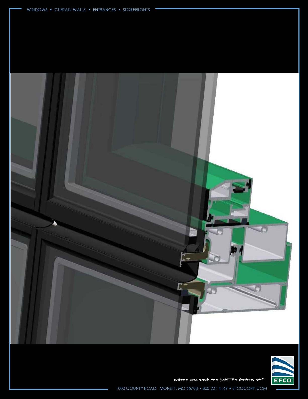
Series 875X WALL Vent
Installation Instructions
for curtain wall
Y808 November 2014
Page 2
Series 875 Vent Table of Contents
TABLE OF CONTENTS PAGES
1. INDEX & NOTES 2
2. GENERAL NOTES 3
3. PARTS IDENTIFICATION 4 - 5
4. 875X TYPICAL DETAILS & FORMULAS 6 - 7
5. VENT & FRAME INSTALLATION 8 - 9
6. SCREEN INSTALLATION 10 - 11
7. 875V TYPICAL DETAILS & FORMULAS 12 - 15
8. 875V ADAPTOR DETAILS & FORMULAS 16 - 28
9. LOCK LOCATIONS & FORMULAS 29 - 31
10. MAINTENANCE 32
Note:
These instructions show the general installation sequence and procedure for typical installations.
Use in conjunction with general service and maintenance manual YSM1 and screen instructions
YW40.
This instruction supplements the shop details and notations for installation. Review all instructions
in there entirety before beginning installation.
EFCO CORPORATION 2014 Page 2
Page 3

Series 875 Vent General Notes
1. MATERIAL HANDLING
The material must be protected against damage. The following precautions are recommended.
a. PROTECTION AND STORAGE: Handle the material carefully. Do not drop from the truck. Stack with adequate
separation so the material will not rub together. Store the material off of the ground. Protect against the elements
and other construction hazards by using a well ventilated covering as required. Remove material from packaging
if it is wet or is located in a damp area.
b. CHECK MATERIAL: Upon arrival, check all material, to ensure that the proper quantities have been received and
that material was not damaged during shipment. Any visibly damaged material must be noted on the freight bill
at the time of receipt. If a claim is required, the receiving party must process a claim with the freight supervisor.
c. CLEANING MATERIAL: Cement, plaster, terrazzo, alkaline and acid-based material used to clean masonry are
very harmful to finishes and should be removed with water and mild soap immediately or permanent staining will
occur. A spot test is recommended before any cleaning agent is used. For more specific cleaning informat ion
reference EFCO's General service and maintenance manual.
NOTE: If a protective coating is specified, remove it in areas that require sealant.
2. GENERAL NOTES: The following practices are recommended for all vent installations:
a. REFERENCE SHOP DRAWINGS: Check shop drawings and installation instructions to becom e thoroughly
familiar with the project. These installations instructions are of a general nature and cover the most common
conditions. The shop drawings take precedence and include specific details for the project.
b. CHECK OPENINGS: Make certain that construction which will receive your material is in accordance with the
contract documents. If not, notify the general contractor in writing and resolve differences before proceeding
with work.
c. BENCHMARK LAYOUT: All work should start from benchmarks and/or column cente rlin es as established by the
architectural drawings and the general contractor.
d. PLUMB / LEVEL / TRUE: All materials are to be installed plumb, level and true.
e. ISOLATION OF ALUMINUM:
Use a heavy coat of zinc chromate or bituminous paint to isolate aluminum
from direct contact with uncured masonry and other incompatible materials.
f. FASTENING: Refers to any method of securing one part to another or to adjacent materials.
g. SEALANTS: Must be compatible with all materials they contact, including other sealant surfaces. Consult the
sealant supplier for recommendations relative to solvent cleaning materials and procedu res, compatibility,
adhesion, priming, tooling and shelf life.
h. BUILDING CODES: Glass and glazing codes governing the design and use of products vary widely. EFCO does
not control the selection of product configurations, operating hardware, or glazing material s, and therefore
assumes no responsibility. It is the responsibility of the owner, specifier, architect, general contractor and the
installer to make these selections in accordance with local building codes.
i. SHIM SPACE INFORMATION: The nominal shim space is 1/8". The maximum shim space is 1/4".
j. SURROUNDING METAL: The surrounding framing shall be a minimum thickness of 0.080".
NOTE: Performance values are based on AAMA standard test size for each specific test configuration. Lock points
can be moved at the head by changing the rod length. If required a lock point can be added under the
handle by adding one Giesse cap head screw 02251K and one H15U keeper . When DLO is greater than
48" in height, one additional lock point is required per jamb at center of vent. If the vent is larger than test
size or the vent has hardware options other than what was used on the test window, some degradation in
performance may occur. Job specific sizes and hardware options can be tested with the appropriate
charges and lead times added to the schedule.
EFCO CORPORATION 2014 Page 3
Page 4
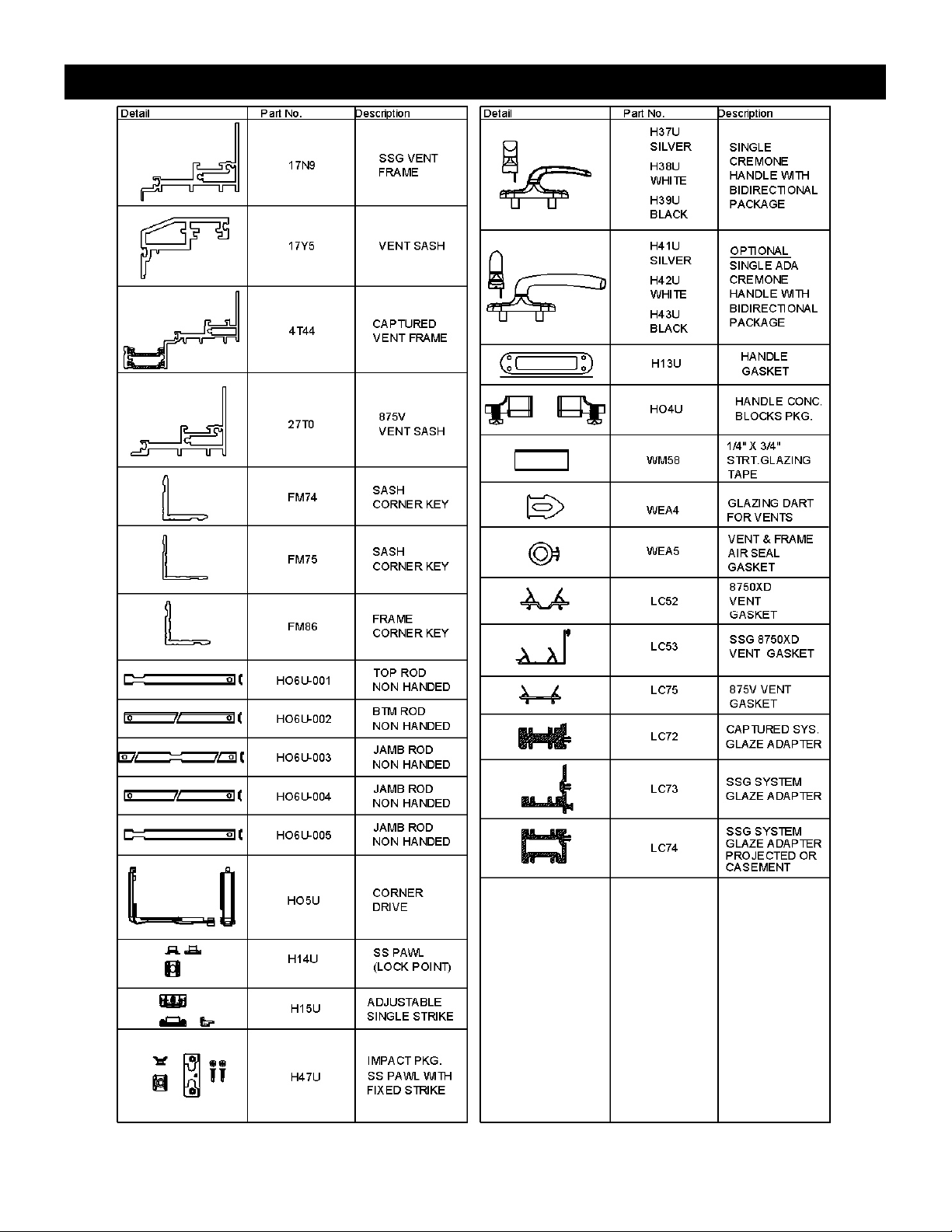
Series 875 Vent Parts Identification
EFCO CORPORATION 2014 Page 4
Page 5
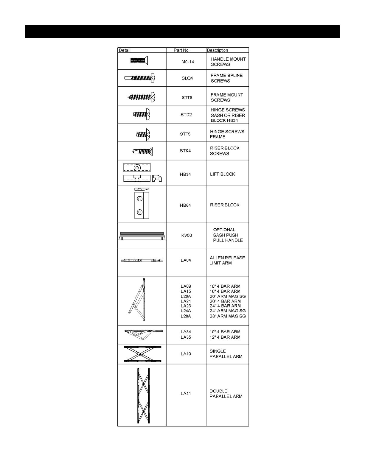
Series 875 Vent Parts Identification
EFCO CORPORATION 2014 Page 5
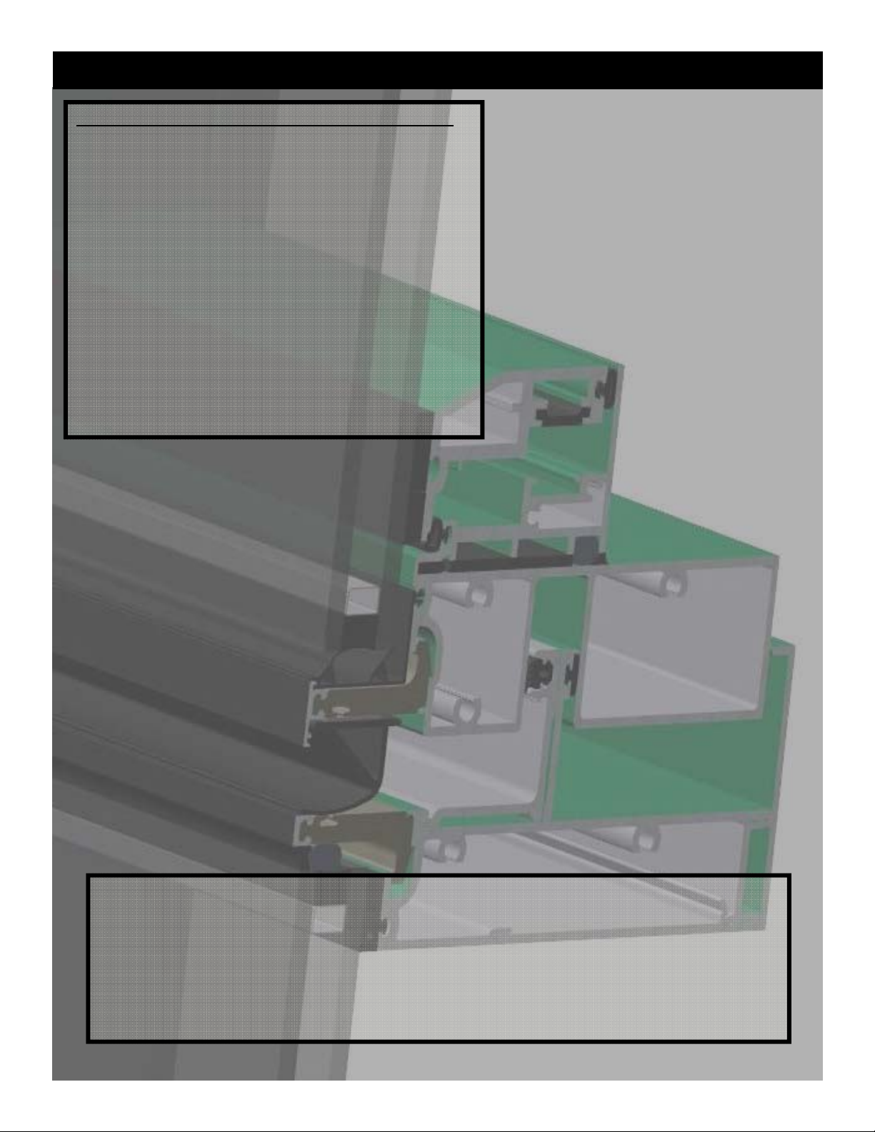
Page 6
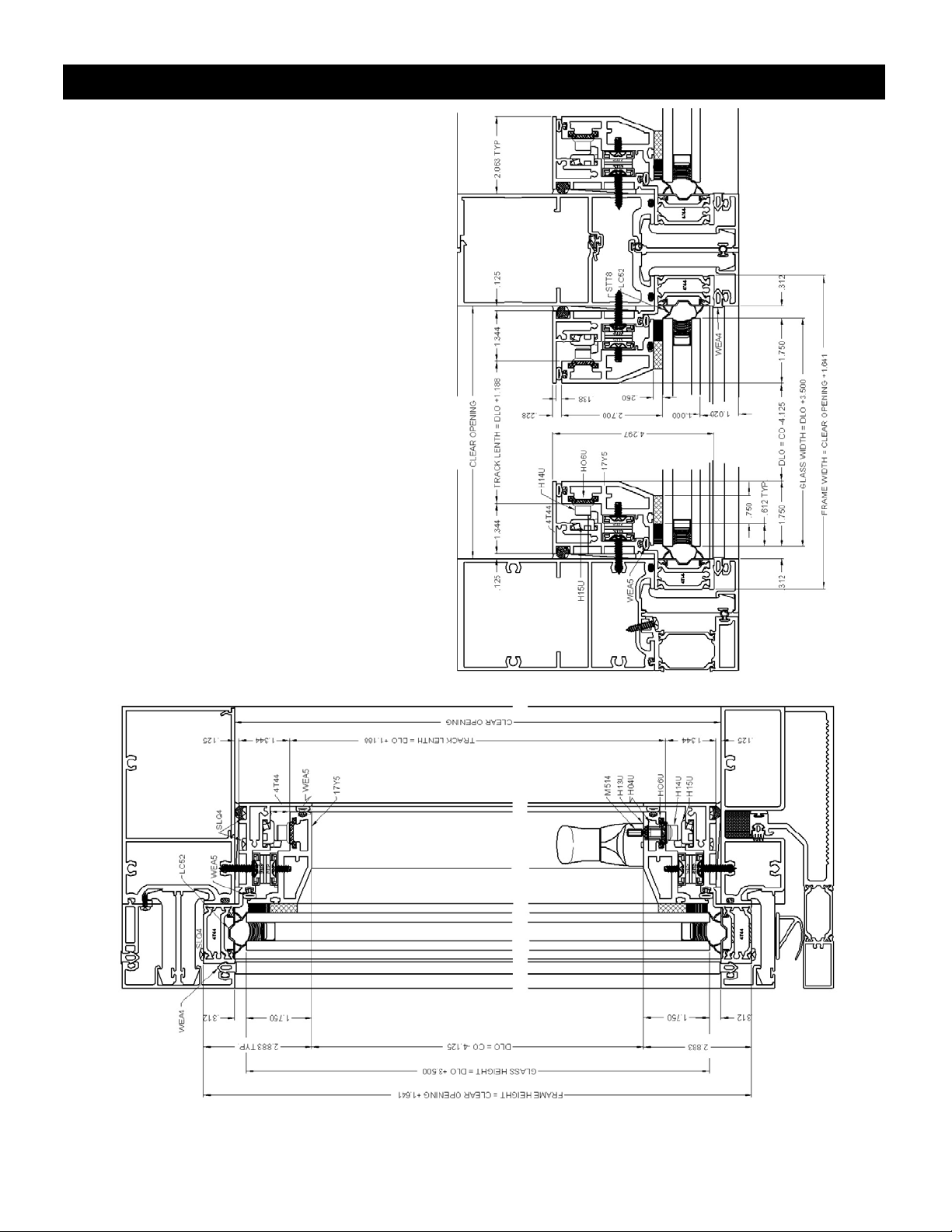
Series 875 Captured Vent
EFCO CORPORATION 2014 Page 6
Page 7
Series 875 SSG Vent
EFCO CORPORATION 2014 Page 7
Page 8
Series 875 Vent Installation
VENT FRAME PREPARATION
1. Do not fasten drapery tracks, ceiling supports or
Stool trims to windows.
2. Fasten window frame into minimum of 0.080"
thickness of framing.
3. Minimum anchor spacing:
a. No more than 6" from each side of frame joints.
b. No more than 18" on center between anchors.
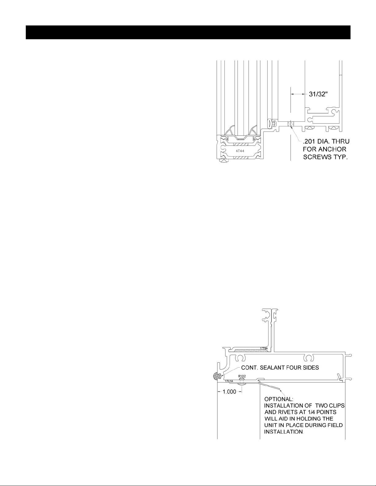
4. Pre-drill using a 0.201 DIA. - #7 drill bit to make anchor
clearance holes in the vent frame. Make
sure screw heads can be reached when vent is installed.
5. Countersunk anchor holes may be required with some hardware combinations. All screw heads must
be sealed at sill.
6. When installing curtain wall pocket adapters, use silicone to seal in place as directed by instructions
and shop drawings.
VENT INSTALLATION
1. Consult curtain wall assembly instructions and shop drawings before vent installation begins.
2. Install optional vent frame retention clips (FM85) if required.
3. Make sure all curtain wall seals covered by the vent are done and tooled before vent installation.
4. Vent frame sizes: curtain wall clear opening -1/4” in both
directions. This will allow 1/8” shimming on all sides.
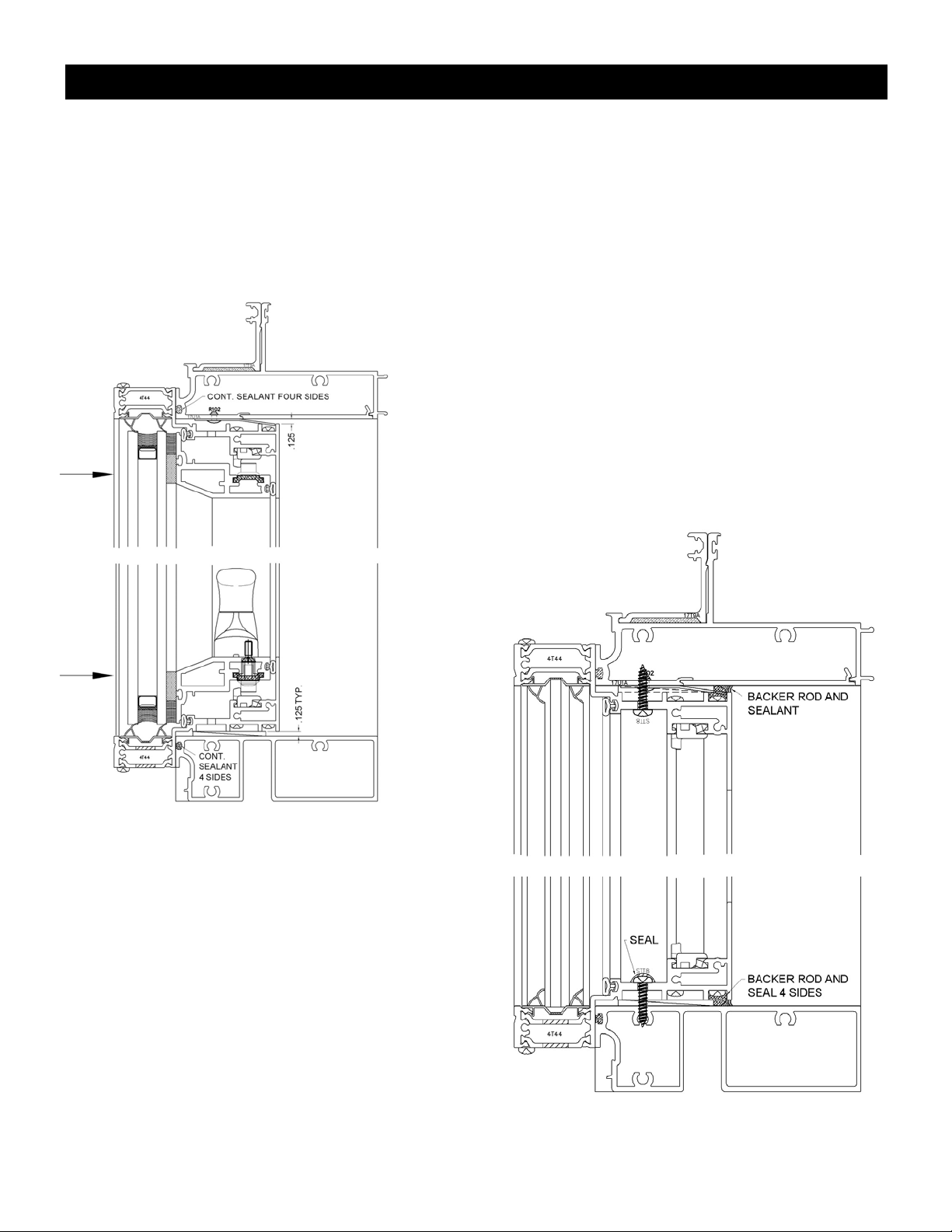
5. Apply a continuous bead of sealant around face of
curtain wall clear opening.
6. Perimeter sealant must be applied to SSG front legs
before frame installation.
7. Perimeter sealant on custom SSG units may be applied
and tooled down after vent frame installation.
EFCO CORPORATION 2014 Page 8
Page 9
Series 875 Vent Installation
8. Place vent on 1/8” shims in clear opening and push in to bed to sealant.
9. If optional clips (FM85) are used you may need to apply shims after placing the vent. A clear snap
should be heard at the head from the clips. Look inside to make sure the clips are seated before opening the vent.
10. Shim vent 1/8” on all sides as needed, making it plumb and
square in the clear opening.
11. Remove the sash if vents are installed horizontally in the
shop.
12. Install anchor screws as needed on all side while still maintaining a plumb and square frame.
13. Reinstall vent and adjust for plumb and square in frame.
14. Check vent operation and locking making necessary
adjustment to the hinges and friction shoes.
15. Seal over screw heads at sill and install backer rod
and sealant in interior gap as needed.
EFCO CORPORATION 2014 Page 9
Page 10
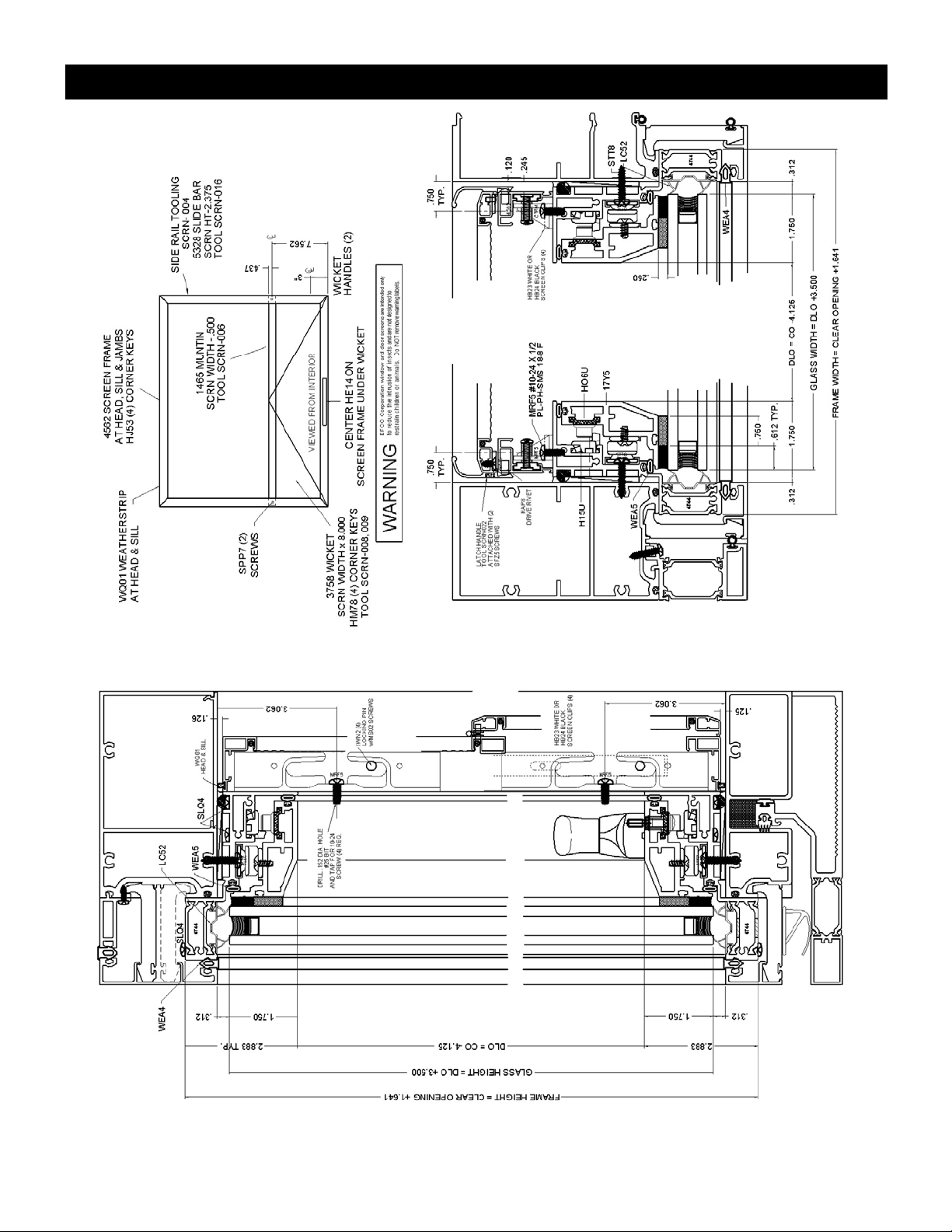
Series 875 Captured Vent With Screen
EFCO CORPORATION 2014 Page 10
Page 11

Series 875 SSG Vent With Screen
EFCO CORPORATION 2014 Page 11
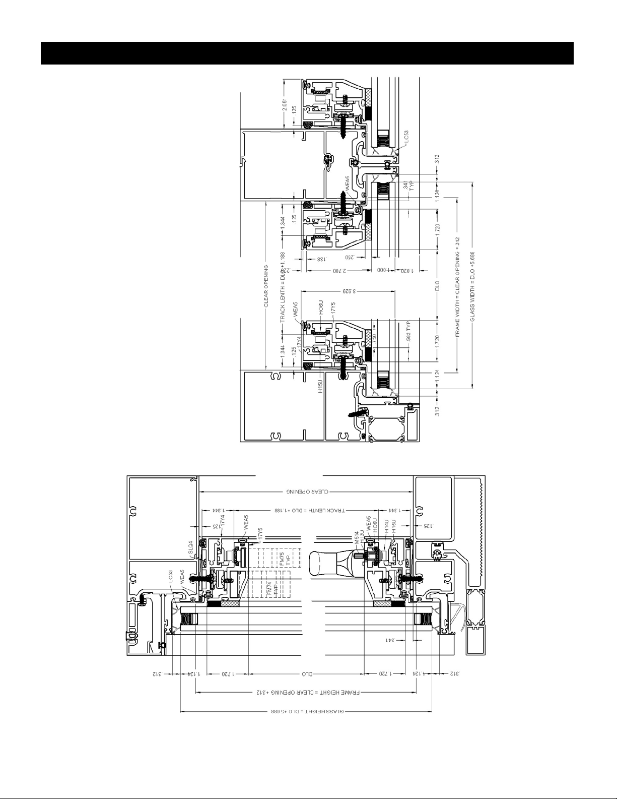
Page 12

Series 875 Adapted to 5600 Curtain Walls
EFCO CORPORATION 2014 Page 12
Page 13

Series 875 Adapted to 5600 Curtain Walls
EFCO CORPORATION 2014 Page 13
Page 14

Series 875 Adapted to 5600 Curtain Walls
EFCO CORPORATION 2014 Page 14
Page 15

Series 875 Adapted to 5600 Curtain Walls
EFCO CORPORATION 2014 Page 15
Page 16

Series 875 Adapter Formulas
EFCO CORPORATION 2014 Page 16
Page 17

Series 875 Adapter Formulas
EFCO CORPORATION 2014 Page 17
Page 18

Series 875 Adapter Formulas
EFCO CORPORATION 2014 Page 18
Page 19

Series 875 Adapter Formulas
EFCO CORPORATION 2014 Page 19
Page 20

Series 875 Adapter Formulas
EFCO CORPORATION 2014 Page 20
Page 21

Series 875 Adapter Formulas
EFCO CORPORATION 2014 Page 21
Page 22

Series 875 Adapter Formulas
EFCO CORPORATION 2014 Page 22
Page 23

Series 875 Adapter Formulas
EFCO CORPORATION 2014 Page 23
Page 24

Series 875 Adapter Formulas
EFCO CORPORATION 2014 Page 24
Page 25

Series 875 Adapter Formulas
EFCO CORPORATION 2014 Page 25
Page 26

Series 875 Adapter Formulas
EFCO CORPORATION 2014 Page 26
Page 27

Series 875 Adapter Formulas
EFCO CORPORATION 2014 Page 27
Page 28

Series 875 Vent Hardware Location
Note: To install hardware, start from the top and work to handle.
Note: To remove hardware, start from the bottom and work toward the top.
EFCO CORPORATION 2014 Page 28
Page 29

Series 875 Vent Lock Pints
EFCO CORPORATION 2014 Page 29
Page 30

Series 875 Vent Keeper Points
Note: Standard keeper locations are measured, using a gage, from inside corners.
EFCO CORPORATION 2014 Page 30
Page 31

Series 875 Maintenance
Hinge Linkage:
Hinge linkages are factory installed and adjusted. Check annually for undue wear.
Clean track of any debris and apply a light machine oil to the track and pivot points. Adjust friction
shoe as required for desired vent operation.
Multi-point Locking:
Lock points are factory installed and adjusted.
There may be up to four locking points on any one side. Check annually for undue wear. Lubricate
with a light machine oil as needed for smooth operation.
Keepers:
Keepers are factory installed and adjusted.
To adjust compression on the weather seals loosen fastener on top of the keeper and slide
tongue in or out and retighten screw. Care must be taken to assure no loss of engagement with
the mating ventilator.
Fasteners:
Check annually for undue loosening and hand tighten when needed.
Weathering:
Check annually for undue damage or wear, change if required.
Minimizing Condensation
Note: Please reference EFCO's "Understanding Condensation" brochure which can be obtained through your EFCO representative.
Condensation will form on any surface when unfavorable conditions (interior temperature and relative humidity and exterior
temperature) are present. When the formation of excessive condensation is a concern, it is highly recommended that a design
professional is utilized to perform an analysis of the shop drawings to recommend the best possible installation methods.
Please contact your EFCO representative for information on EFCO's Thermal Analysis Services.
Many current installation practices lead to an increase in the possibility of the formation of condensation. Though not all inclusive,
the list of examples below illustrates conditions under which condensation is likely to occur:
1. Bridging system thermal break with non-thermally broken metal flashing or lintels that are exposed to the exterior
2. System exposure to cold air cavities
3. Interior relative humidity levels not maintained at recommended levels, see EFCO’s “Understanding Condensation”
Brochure
4. Inadequate separation between system and surrounding condition at perimeter
5. Product combinations during the shop drawing stage that result in bridging thermal breaks
of one or all products involved.
EFCO CORPORATION 2014 Page 31
 Loading...