

Page 1
SERIES 8750XD UNITIZED CURTAIN WALL
Installation Instructions Sections 1-15
Nov 2012
PART NO. Y80B
1000 COUNTY ROAD MONETT, MO 65708 • 800.221.4169 • EFCOCORP.COM
Page 2

Series 8750XD Unitized Curtain Wall Installation Instructions
Series 8750XD Unitized Curtain Wall Installation Instructions
Table Of Contents
SECTION PAGES
1. General Notes and Guidelines………………………………………………………………………………………………………………………………
2. Parts Identification…………………………………………………………………………………………………………………………………………….
3. Static Starter Sill Preparation and Installation……………………………..…………………………………………………………………………….
4. Dynamic Starter Sill Preparation and Installation…………………..………………..………………………………………………………………….
5. Intermediate Floor Slab Anchor Installation……………………………………….....………………………………………………………………….
6. Unit Inspection and Preparation for Installation……………………………..….......………………………………………………………………….
7. Setting Units at Static Starter Sills………………………………………………..…....………………………………………………………………….
8. Setting Units at Dynamic Starter Sills………………………………………………….……………………… ………………………………………….
9. Applying Critical Seals and Stack Gaskets……………………………………...……………………………………………………………………….
10. Setting Typical intermediate Units….......................................................................………………………………………………………………….
11. Setting Typical Head Condition Units………………………………………………….………………………………………………………………….
12. Setting Typical 90 Degree Corner Units……………………………………………….………………………………………………………………….
13. Appling Typical Perimeter Seals………………………………………………………..…………………… …………………………………………….
14. Deglaze / Re-glaze Procedures - Captured System................................................………………………………………………………………….
15. Deglaze / Re-glaze Procedures - SSG System…….................................................………………………………………………………………….
3 - 4
5 - 11
12 - 18
19 - 22
23 - 24
25 - 27
28 - 30
31 - 32
33
34 - 35
36
37
38
39 - 40
41 - 43
Minimizing Condensation
Note: Please reference EFCO's "Understanding Condensation" brochure which can be obtained through your EFCO representative.
Condensation will form on any surface when unfavorable conditions (interior temperature and relative humidity and exterior temperature) are present. When the formation of excessive condensation is a concern, it is highly recommended that a design professional is utilized to perform an analysis of the shop drawings to recommend the best possible installation methods. Please contact your EFCO representative for information on EFCO's Thermal Analysis Services.
Many current installation practices lead to an increase in the possibility of the formation of condensation. Though not all inclusive, the list of examples below illustrates conditions
under which condensation is likely to occur:
Note: Assembly Instructions ( Y807 ) are provided as a supplement, and should be used in conjunction with the approved shop drawings.
EFCO 2012 Page 2
EFCO 2012 Page 2
1. Bridging system thermal break with non-thermally broken metal flashing or lintels that are exposed to the exterior
2. System exposure to cold air cavities
3. Interior relative humidity levels not maintained at recommended levels, see EFCO’s “Understanding Condensation” brochure
4. Inadequate separation between system and surrounding condition at perimeter
5. Product combinations during the shop drawing stage that result in bridging thermal breaks
of one or all products involved.
Page 3

Series 8750XD Unitized Curtain Wall Installation Instructions
Section 1: General Notes And Guidelines
HANDLING / STORING / PROTECTING ALUMINUM
The following guidelines are recommended to ensure early acceptance of your
products and workmanship.
A. HANDLE CAREFULLY - Store with adequate separation between
components so the material will not rub together. Store the material off the
ground. Protect materials against weather elements and other
construction trades.
B. KEEP MATERIAL AWAY FROM WATER, MUD, AND SPRAY - Prevent
cement, plaster, and other materials from contacting with and damaging
the finish. Do not allow moisture to be trapped between the finished
surface and the wrapping material.
C. PROTECT MATERIALS AFTER ERECTION - Wrap or erect screens of
plastic sheeting over material. Cement, plaster, terrazzo, and other
alkaline materials are very harmful to the finish and are to be immediately
removed with soap and water. Under no circumstances should these
materials be allowed to dry or permanent staining may occur.
GENERAL GUIDELINES
The following practices are recommended for all installations:
A. REVIEW CONTRACT DOCUMENTS – Become thoroughly familiar with
the project. Check shop drawings, installation instructions, architectural
drawings and shipping lists. The shop drawings take precedence and
include specific details for the project. Shop drawings govern when
conflicting information exists in the assembly and installation instructions.
Note any field verified notes on the shop drawings prior to installing.
EFCO assembly and installation instructions are general in nature and
cover many conditions.
B. INSTALL ALL FRAMING MATERIAL PLUMB, LEVEL, AND TRUE –
Proper alignment and relationships to benchmarks and column
centerlines, as established by the architectural drawings and the general
contractor, must be maintained.
C. ERECTION SEQUENCE - The sequence of erection should be
coordinated with the project general contractor to prevent delays and
minimize the risk of material damage. Note: When preset anchors are
required, coordinate and supervise anchor and insert placement with the
general contractor including insert layout drawings, where required.
Manufacturing, assembly, glazing, and shipment of the preglazed units
must be carefully coordinated with the general contractor to ensure a
continuous and sustained flow of materials to the appropriate areas of the
project to meet the project schedule.
D. PERIMETER CONDITIONS - Verify that all job site co nditions and
accompanying substrates receiving the installation are in accordance with
the contract documents. If deviations occur, notification must be given in
writing to the general contractor and differences resolved before
proceeding further with the installation in the area in question.
E. ISOLATION OF ALUMINUM - Prevent all aluminum from coming in direct
contact with masonry or dissimilar materials by means of an appropriate
primer. Typical slab anchors may be set directly onto concrete surfaces in
a block-out pocket at the edge of the slab. The block-out pocket is later
filled in with grout thereby covering the slab anchor. In such cases, a
heavy coat of zinc chromate or bituminous paint must be pre-applie d to
the slab anchor.
F. SHIPMENT VERIFICATION - Verify contents of all material shipments
received upon their arrival. Verify quantity and correct finishes. Notify
EFCO immediately of any discrepancies or damage that may have
occurred.
G. SEALANT - All sealant must meet [ASTM C 920, CLASS 50]. For the
purposes of these instructions, sealant is to be defined as the following:
SEALANT - A weather resistant, gunnable liquid filler which when cured
provides a resilient, flexible (± 50% movement capability min.) air and
water seal between similar and dissimilar materials.
All sealant must be compatible with all surfaces on which adhesion is
required, including other sealant surfaces. All frame surfaces should be
clean, dry, dust, and frost free. If a primer is required, it must be applied to
clean surfaces. All perimeter substrates shall be clean and properly
treated to receive sealant. All sealants and primers must be applied
according to the sealant manufacturers instructions and
recommendations.
This system is designed and has been tested to utilize silicone sealants at
all internal joineries, i.e., joint plugs, gasket intersections, etc.
EFCO 2012 Page 3
Page 4
Series 8750XD Unitized Curtain Wall Installation Instructions
Section 1: General Notes And Guidelines
It is the responsibility of the glazing contractor to submit a statement from
the sealant manufacturer indicating that glass and glazing materials have
been tested for compatibility and adhesion with glazing sealants, and
interpreting test results relative to material performance, including
recommendations for primers and substrate preparation required to obtain
adhesion. The chemical compatibility of all glazing materials and framing
sealants with each other and with like materials used in glass fabrication
must be established.
Maintain caulk joints as shown in the approved shop drawings. A 1”
minimum joint is required at the head and jamb condition to accommodate
installation, building movements, and thermal expansion and contraction.
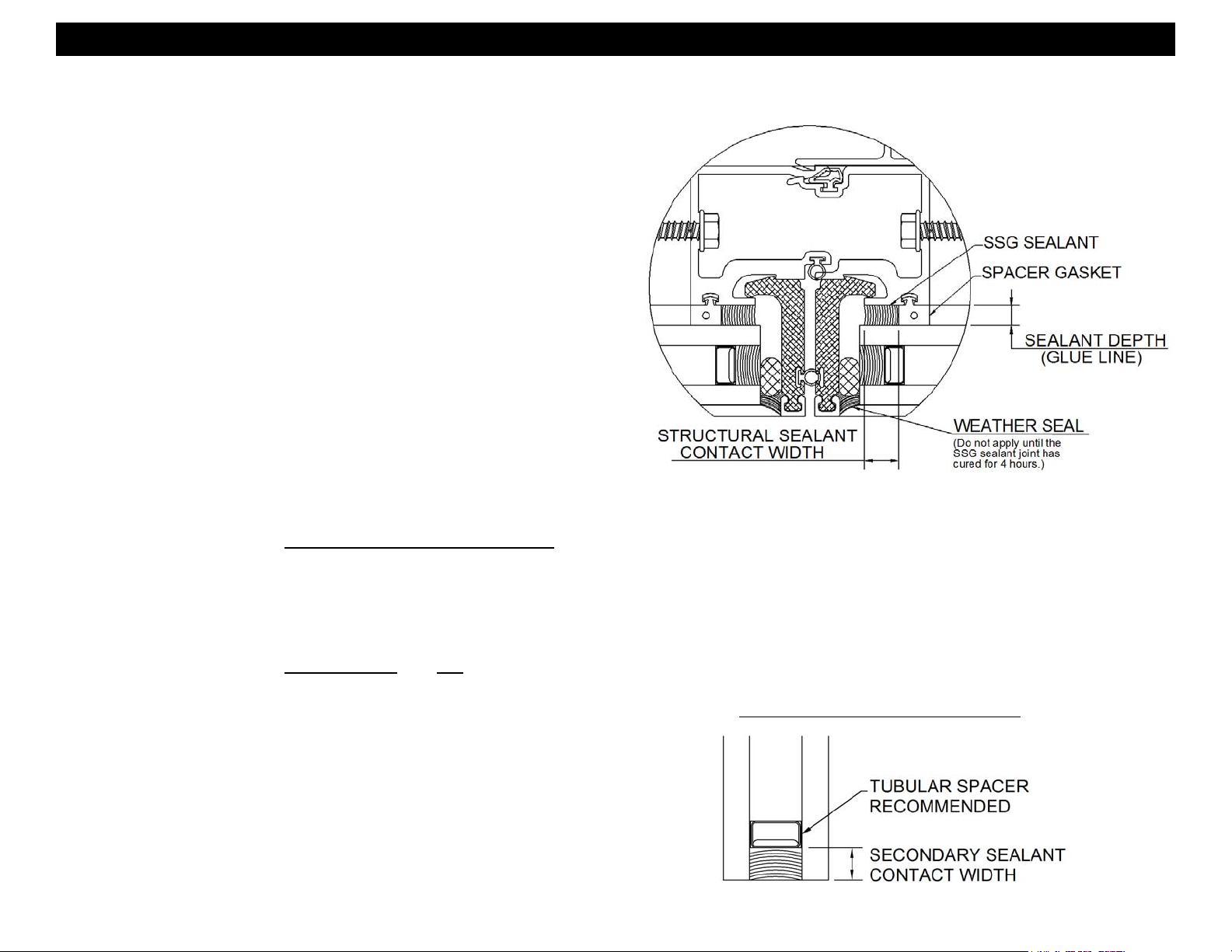
H. STRUCTURAL SEALANT JOINTS - The maximum allowable size of the
glass lite is controlled by the width and depth of the structural silicone joint
combined with the specified design wind load (PSF or Pa). The stress on
the structural silicone must not exceed 20 PSI (137 KPa) for a 6:1 safety
factor.
In order to determine the structural silicone sealant contact width or bite
which adheres the glass to the frame, a calculation must be performed on a
job by job basis. The formula which determines the sealant width is based
on using a trapezoidal load distribution rule. This formula is expressed as
follows:
Structural Sealant = 0.5 x Short Span (ft) x Wind load (lb/ft²)
Bite or Contact Width (in) Sealant Design Strength (=20 lb/in²) x 12 in/ft
Example: Lite size is 4’0” x 5’0” and wind load for the project is 60 psf.
Structural Sealant = 0.5 x 4’ x 60 psf
Bite or Contact Width (in) 20 x 12 240
Sealant manufacturers, as a general rule, specify the structural sealant
depth (glue line) to be one half of the contact width for a 2:1 width to height
ratio. The glue line should not exceed 3/8” thickness nor be less than 1/4”
thick. The standard joint size for Series 8750XD is 1/2” x 1/4”. Note:
Weather seals must be applied a minimum of four hours after the
application of the SSG sealant joint to allow for proper cure time.
or 120 or .500”
SECONDARY SEALANT JOINT DETAIL
I. SECONDARY SEALANT JOINT DESIGN - The design of the secondary
sealant joint is based on the 50:50 load sharing principal where the I.G. unit
is comprised of two symmetrical lites of glass. The secondary sealant joint
that adheres the two lites of glass together only carries half the wind load
applied to the I.G. unit. Since the load is halved, the secondary sealant
contact width is half that of the SSG joint. Using the example earlier for the
1/2” x 1/4” SSG joint, the secondary sealant contact width for the I.G. unit in
the example is 1/4”.
Edge deletion is required on the coated surface (#2 or #3) for hard or soft
coated glazing products.
SECONDARY SEALANT JOINT DETAIL
EFCO 2012 Page 4
Page 5
Series 8750XD Unitized Curtain Wall Installation Instructions
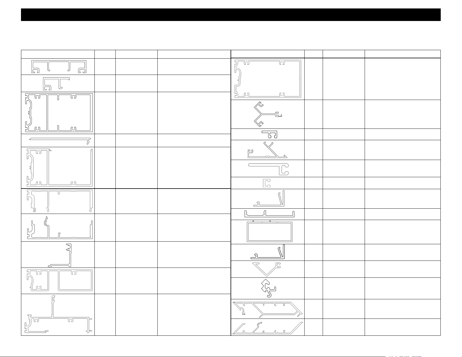
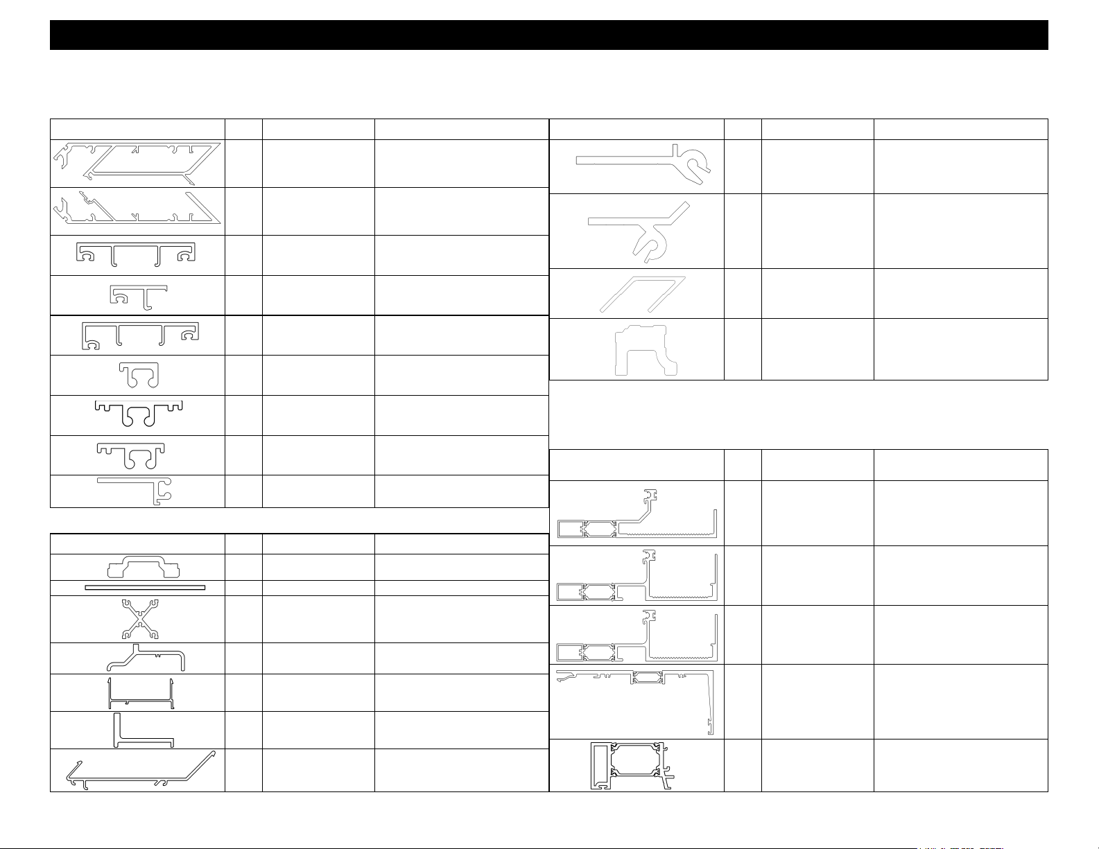
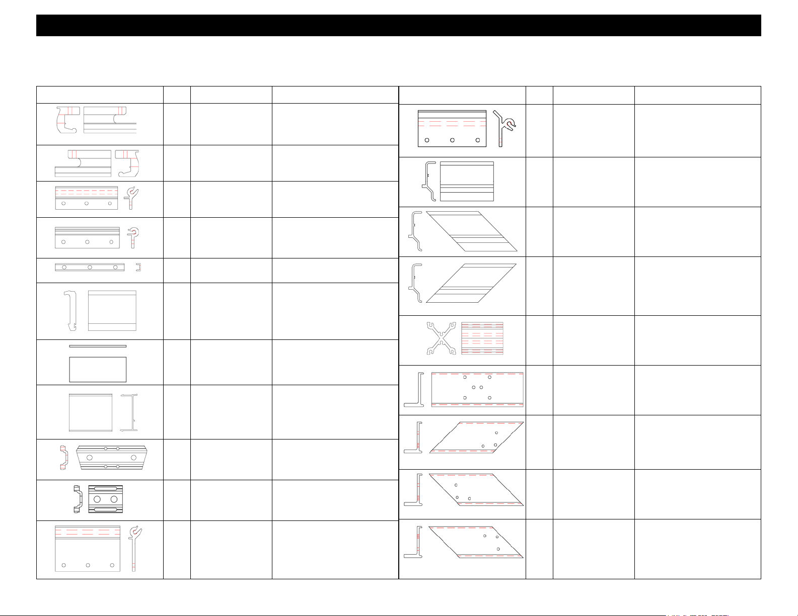
EXTRUSION IDENTIFICATION
Profile Part # Description Tooling/Cut Length Formula
17T1
17T2
17T3
17T5
17T6
17T7
17T8
3" STANDARD
COVER
STANDARD
HALF COVER
STANDARD
INTERMEDIATE
HORIZONTAL
HEAD OR JAMB
FILLER
HEAD
OR CUSTOM
JAMB
SPLIT MULLION
#1
SPLIT MULLION
#2
Section 2 - Parts Identification
EXTRUSION IDENTIFICATION
Profile Part # Description Tooling/Cut Length Formula
17T1-001
17T2-001
17T3-001, 17T3-002, 17T3-003,
17T3-004, 17T3-005, 17T3-006,
17T3-007, 17T3-008, 17T3-009,
17T3-010, 17T3-01
17T5-001, 17T5-002, 17T5-003,
17T5-004, 17T5-005, 17T5-006
17T6-001, 17T6-002, 17T6-003,
17T6-004, 17T6-005, 17T6-006
17T7-001, 17T7-002, 17T7-003,
17T7-004, 17T7-005, 17T7-006
17T8-001, 17T8-002, 17T8-003,
17T8-004, 17T8-005, 17T8-006
17U3
17U4
17V1
17V2
17V3
17V4
17V5
17V6
17V9
SSG
HORIZONTAL
90 DEG INSIDE
CORNER COVER
SSG DROP LEG
COVER
90 DEG OUTSIDE
CORNER COVER
EXTENDED LEG
SSG COVER
STANDARD SSG
COVER
5/8" THERMAL
DOOR STOP
COVER
INTERIOR HORIZ.
SNAP TRIM
TRANSOM DOOR
HEADER
17U3-001, 17U3-002, 17U3-003
17U4-001
17V1-001
17V2-001
17V3-001, 17V3-002, 17V3-003,
17V3-004, 17V3-005, 17V3-006,
17V3-007
17V4-001
DOOR FRAME CLEAR OPENING
(NEED PREP)
STOCK LENGTH
(NEED PREP)
DOOR FRAME CLEAR OPENING
(NEED PREP)
17T9
17U0 STACK SILL
17U1 STACK HEAD
SNAP IN
NECK
17T9-001, 17T9-002, 17T9-003,
17T9-004, 17T9-005,
17T9-006
17U0-001, 17U0-002, 17U0-003,
17U0-004, 17U0-005, 17U0-006
17U1-001, 17U1-002, 17U1-003,
17U1-004, 17U1-005, 17U1-006
17W2
17W3
17W4
17W6
17W7
1/2" THERMAL
DOOR STOP
COVER
SSG 90 DEG
OUTSIDE COR-
NER COVER
SSG 90 DEG
INSIDE CORNER
COVER
MALE 90 DEG
INSIDE CORNER
HALF
FEMALE 90 DEG
INSIDE CORNER
HALF
DOOR FRAME CLEAR OPENING
(NEED PREP)
17W3-001
17W4-001
17W6-001, 17W6-002, 17W6-003,
17W6-004, 17W6-005, 17W6-006
17W6-007
17W7-001, 17W7002, 17W7-003,
17W7-004, 17W7-005, 17W7-006
17W7-007
EFCO 2012 Page 5
Page 6
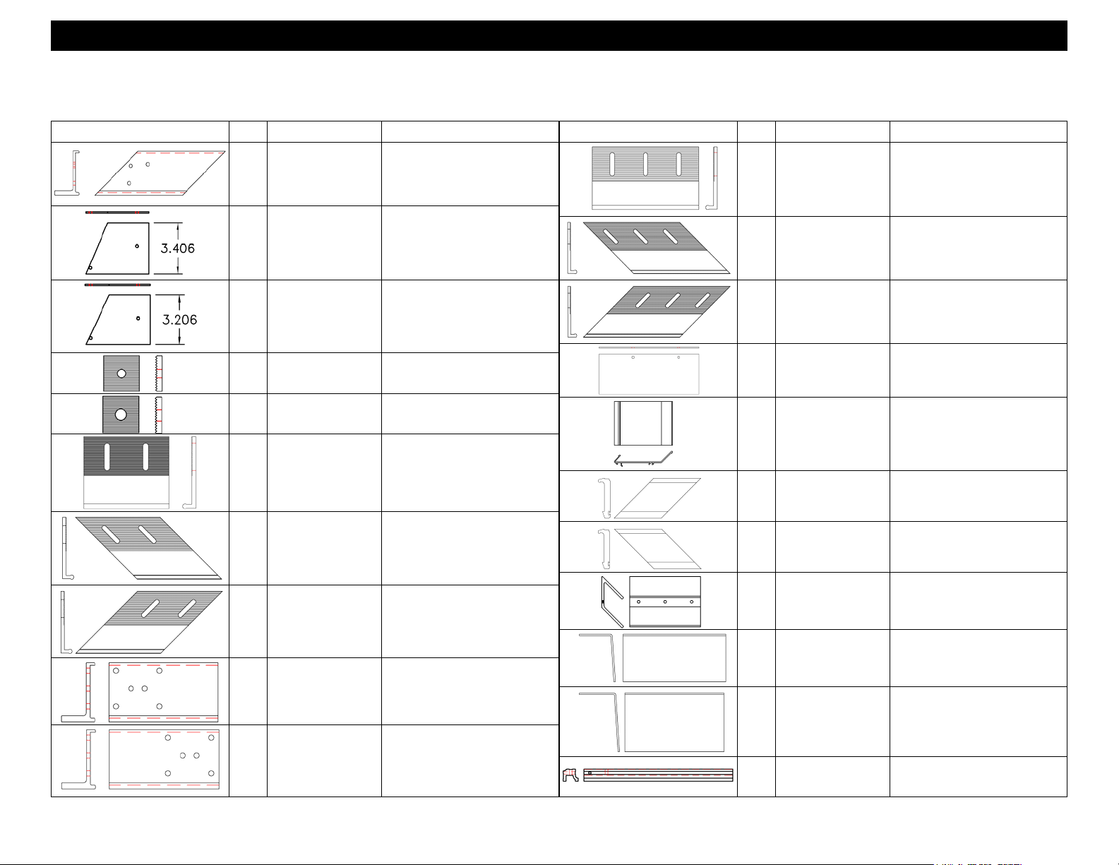
Series 8750XD Unitized Curtain Wall Installation Instructions
Section 2 - Parts Identification
EXTRUSION IDENTIFICATION
Profile Part # Description Tooling/Cut Length Formula
17W8
17W9
17X5
17X6
17X7
17X8
17X9
17Y0
17Y1
MALE OUTSIDE
CORNER HALF
FEMALE OUTSIDE
CORNER HALF
3" COVER FOR
1 1/4" GLAZING
AND VENTS
HALF COVER FOR
1 1/4" GLAZING
AND VENTS
3" COVER FOR 1"
GLAZING OVER
VENTS
STANDARD SSG
COVER FOR VENT
LOCATIONS
SSG COVER INTER.
HORIZONTAL VENT
OVER VENT
SSG COVER FOR
VENTS AT SILL OR
HORIZONTAL
SSG COVER FOR
VENTS AT JAMBS
17W8-001, 17W8-002, 17W8-003,
17W8-004, 17W8-005, 17W8-006,
17W9-001, 17W9-002, 17W9-003,
17W9-004, 17W9-005, 17W9-006,
FABRICATED PART EXTRUSION IDENTIFICATION
Profile Part # Description Tooling/Cut Length Formula
17T4 HANGER FM41
17U2 .090 X 3.000 BAR FM39
17W8-007
17W9-007
17X5-001
17X6-001
17X7-001
17X8-001
17X9-001
17Y0-001
17Y1-001
FABRICATED PART EXTRUSION IDENTIFICATION
Profile Part # Description Tooling/Cut Length Formula
17X0
17X1
17Z7
17Z8
90° OUTSIDE COR-
NER MULLION AN-
CHOR
90° INTSIDE COR-
NER MULLION AN-
CHOR
INSIDE OUTSIDE
CORNER GUIDE
CLIP
SUN SHADE
BRACKET
COMPOSITE IDENTIFICATION
Profile Part # Description Tooling/Cut Length Formula
1H91 STATIC SILL CAN
1H92 DYNAMIC SILL CAN
FM43
FM44
FM78
FM82
STOCK LENGTH
1H91-001
STOCK LENGTH
1H92-001
17U8
17U9 STATIC LOAD CLIPS FM45, FM46 & FM47
17V0 SPLIT MULL CLIP FM40
17V8
17W5 CORNER SNAP CLIP FM70
DYNAMIC LOAD
CLIPS
DYNAMIC LOAD
CLIPS
FM48
FM49, FM50, FM51,
FM52 & FM53
1H93 DOOR ADAPTOR
1H94
1H97
SUB HEAD FOR 7
1/2" SYSTEM DEPTH
SCREW APPLIED
THERMAL JAMB
ADAPTOR
FABRICATED ONLY
(NEED PREP)
FABRICATED ONLY
(NEED PREP)
STOCK LENGTH
EFCO 2012 Page 6
Page 7
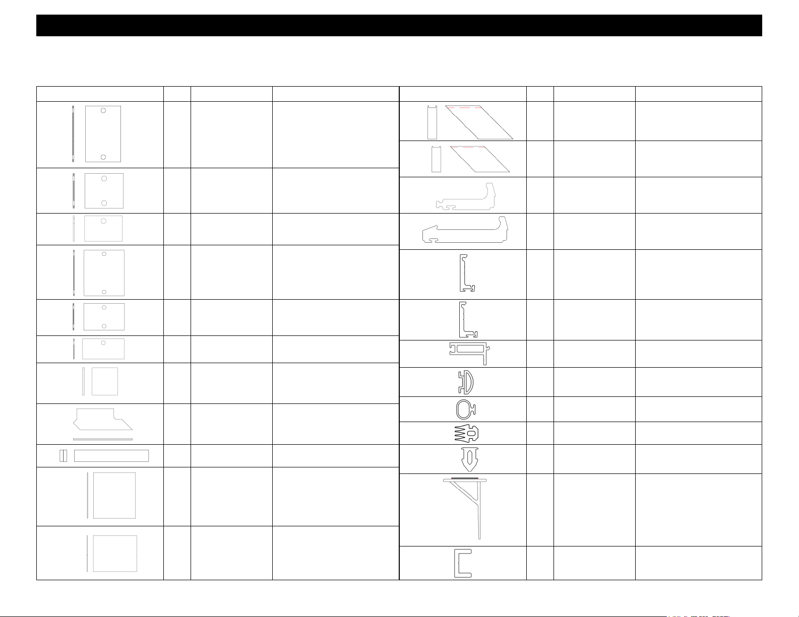
Series 8750XD Unitized Curtain Wall Installation Instructions
Section 2 - Parts Identification
“ F ” PART IDENTIFICATION
Profile Part # Description Materials
FM05
FM06
FM07
FM11 MULLION ANCHOR 17D1 (MILL)
FM17
FM38
FM39
FM40
FM41
FM42
HOOK ANCHOR
(LEFT)
HOOK ANCHOR
(RIGHT)
90 DEG OUTSIDE
CORNER MULLION
ANCHOR
ANCHOR BOLT
RETAINER
LARGE DURACAST
CLIP
SILL CAN END CAP
BEHIND DOOR
JAMB
SPLIT MULLION
ATTACHMENT CLIP
RIGHT HAND
HANGER/LOAD CLIP
OPTIONAL RE-
TRACTABLE
HANGER
17D2 (MILL)
17D2 (MILL)
17F3 (MILL)
12D8 (MILL)
LC46
PAINTED DARK BROWN
17U2
FINISH PER JOB
17V0
CLEAR ANODIZED
17T4 (MILL)
17T4 (MILL)
“ F ” PART IDENTIFICATION
Profile Part # Description Materials
FM44
FM45
FM46
FM47
FM48
FM49
FM50
FM51
90 DEG INSIDE
CORNER MULLION
ANCHOR
STATIC SILL
LOADING CLIP
LEFT HAND STATIC
SILL LOADING CLIP
FOR 90 DEG OUT-
SIDE CORNERS
RIGHT HAND
STATIC SILL LOAD-
ING CLIP FOR 90
DEG OUTSIDE COR-
NERS
DYNAMIC LOAD
CLIP (TOP HALF)
DYNAMIC LOAD
CLIP (BASE)
LEFT HAND 90 DEG
INSIDE CORNER
DYNAMIC LOAD
CLIP (BASE)
RIGHT HAND 90
DEG INSIDE COR-
NER DYNAMIC
LOAD CLIP (BASE)
17X1 (MILL)
17U9 (MILL)
17U9 (MILL)
17U9 (MILL)
17U8 (MILL)
17V8 (MILL)
17V8 (MILL)
17V8 (MILL)
LEFT HAND 90 DEG
OUTSIDE CORNER
DYNAMIC LOAD
CLIP (BASE)
17V8 (MILL)
FM43
90 DEG OUTSIDE
CORNER MULLION
ANCHOR
17X0 (MILL)
FM52
EFCO 2012 Page 7
Page 8
Series 8750XD Unitized Curtain Wall Installation Instructions
Section 2 - Parts Identification
“ F ” PART IDENTIFICATION
Profile Part # Description Materials
FM53
FM55
FM56
FM59
FM60
FM61 11" SLAB ANCHOR 17D4 (MILL)
RIGHT HAND 90
DEG OUTSIDE COR-
NER DYNAMIC
LOAD CLIP (BASE)
DYNAMIC SILL END
DAM
STATIC SILL END
DAM
SERRATED
WASHER FOR 3/8"
FASTENER
SERRATED
WASHER FOR 1/2"
FASTENER
17V8 (MILL)
.090 THICK ALUMINUM SHEET
(MILL)
.090 THICK ALUMINUM SHEET
(MILL)
17D3 (MILL)
17D3 (MILL)
“ F ” PART IDENTIFICATION
Profile Part # Description Materials
FM66
FM67
FM68
FM69
FM70
FM71
16" HIGH LOAD
SLAB ANCHOR
LEFT HAND HIGH
LOAD SLAB AN-
CHOR FOR COR-
NERS
RIGHT HAND HIGH
LOAD SLAB AN-
CHOR FOR COR-
NERS
SUB HEAD END
DAM
INSIDE/OUTSIDE
CORNER MULLION
ATTACHMENT CLIP
DURACAST COR-
NER CLIP #1
17D4 (MILL)
17D4 (MILL)
17D4 (MILL)
.090 THICK ALUMINUM (MILL)
17W5
CLEAR ANODIZED
LC46
PAINTED DARK BROWN
FM62
FM63
FM64
FM65
LEFT HAND SLAB
ANCHOR FOR 90
DEG CORNERS
RIGHT HAND SLAB
ANCHOR FOR 90
DEG CORNERS
LEFT HAND JAMB
DYNAMIC LOAD
CLIP (BASE)
RIGHT HAND JAMB
DYNAMIC LOAD
CLIP (BASE)
17D4 (MILL)
17D4 (MILL)
17V8 (MILL)
17V8 (MILL)
FM72
FM78
FM79
FM80
FM82
DURACAST COR-
NER CLIP #2
CORNER ALIGN-
MENT CLIP
SPLICE SLEEVE
FOR 17N1 SUB
HEAD
SPLICE SLEEVE
FOR 1H94 SUB
HEAD
SUNSHADE
BRACKET FOR 11" &
13" ARMS
PAINTED DARK BROWN
17X7 (MILL)
ABB2 (MILL)
SHEET ALUM
ABB2 (MILL)
SHEET ALUM
17Z8 (MILL)
EFCO 2012 Page 8
LC46
Page 9
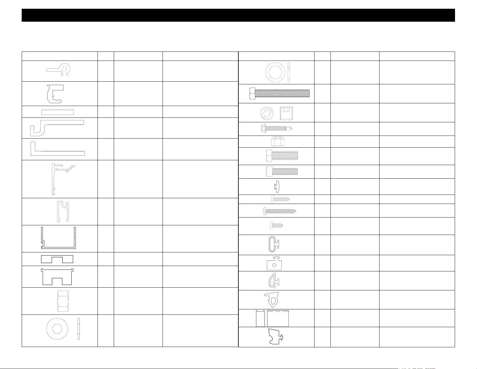
Series 8750XD Unitized Curtain Wall Installation Instructions
Section 2 - Parts Identification
PART IDENTIFICATION
Profile Part # Description Materials
H12A
H12B
H12C
H12D
H12E
H12F
FIXED FRAME
GASKET #1
FIXED FRAME
GASKET #2
FIXED FRAME
GASKET #3
90 DEG CORNER
FRAME GASKET #1
90 DEG CORNER
FRAME GASKET #2
90 DEG CORNER
FRAME GASKET #3
PVC FOAM (BLACK)
PVC FOAM (BLACK)
PVC FOAM (BLACK)
PVC FOAM (BLACK)
PVC FOAM (BLACK)
PVC FOAM (BLACK)
EXISTIING EXTRUSIONS, PARTS, FASTENERS & WEATHERING ID
Profile Part # Description Materials
HD25
HD26
LC45
LC46
LC47
LC48
LC50
CAPTURED OUT-
SIDE CORNER
JOINT PLUG
CAPTURED INSIDE
CORNER JOINT
PLUG
SSG THERMAL
SPACER
STANDARD THER-
MAL SPACER
1/2" THERMAL
DOOR STOP BASE
5/8" THERMAL
DOOR STOP BASE
THERMAL POCKET
FILLER
EPDM GP SPONGE (BLACK)
EPDM GP SPONGE (BLACK)
DURACAST
(PAINTED DARK BROWN)
DURACAST
(PAINTED DARK BROWN)
HIGH IMPACT
PVC (BLACK)
HIGH IMPACT
PVC (BLACK)
HIGH IMPACT
PVC (BLACK)
H12G
H12H
HC05
HC13
HC14
MULLION CAP
GASKET
90 DEG CORNER
MULLION CAP
GASKET
FOAM SEALANT
BACKER
FIXED FRAME
SILICONE SPLICE
SHEET
SSG FRAME
SILICONE SPLICE
SHEET
PVC FOAM (BLACK)
PVC FOAM (BLACK)
PVC FOAM (GREY)
SILICONE SHEET (BLACK)
SILICONE SHEET (BLACK)
WA12
WC20
WEA2 STACK GASKET EPDM (BLACK)
WEA4
LC54 STACK SWEEP PVC WITH VHB TAPE
12D8
SUBHEAD WEATH-
ERING
INSIDE CORNER
EXTERIOR BULB
GLAZING DART
FOR VENTS
BOLT RETAINER
EXTRUSION
ALCRYN AND
PVC (BLACK)
EPDM (BLACK)
SANTOPRENE (BLACK
12D8 (MILL)
EFCO 2012 Page 9
Page 10
Series 8750XD Unitized Curtain Wall Installation Instructions
Section 2 - Parts Identification
EXISTIING EXTRUSIONS, PARTS, FASTENERS & WEATHERING ID EXISTIING EXTRUSIONS, PARTS, FASTENERS & WEATHERING ID
Profile Part # Description Tooling/Cut Length Formula
Profile Part # Description Materials
17D1
17D2
17D3
17M6
17M7
17N1
9123
9914
HN09
HN32
MULLION ANCHOR
EXTRUSION
STANDARD HOOK
ANCHOR EXTRU-
SION
SILL WASHER EX-
TRUSION
UNDER SLAB AN-
CHOR EXTRUSION
SLAB ANCHOR
EXTRUSION
SUB HEAD COVER
EXTRUSION
HEADER GLASS
STOP
HEADER DOOR
STOP
STANDARD SET-
TING BLOCK
HEADER SETTING
BLOCK
17D1 (MILL)
17D2 (MILL)
17D3 (MILL)
17M6 (MILL)
17M7 (MILL)
17N1
FINISH PER JOB
9123
FINISH PER JOB
9914
FINISH PER JOB
HNO9
SILICONE
HN32 SILICONE
M141
M169
M170
M171
M173
M174
MTZ0 UNIT HANGER BOLT
LC23 NECK SPACER PVC (BLACK)
SPZ1 END DAM SCREW #8-15 X 3/4 PL-PH-SMS 18-8 AB
SPZ3
STC7
WA02
WC18
WC21
HANGER LOCK
WASHER
SLAB HANGER
JACKING BOLT
SLAB HANGER
JACKING SCREW
SLAB HANGER
LOCKING SCREW
UNIT HANGER BOLT
LOCK NUT
MULLION MOUNT-
ING BOLT
DOOR STOP
MOUNTING SCREW
JAMB/HEAD END
DAM MOUNTING
SCREW
BULB WEATHERING
FOR DURACAST
OFFSET SSG
SPACER
VERTICAL STACK
AIR SEAL
M141 SPRGLW BLK STL
MS 18-8 #1/2-13 X 3 1/2
1/2"-13 X 1/2" SOCKET SET
SCREW
W/ CUP POINT STEEL
#1/4-14 X 1 1/2 HW- -SMS SG
TEK/3
1/4-20 NYLON INSERT HEX NUT
-18-8
MTZ0 - 1/4"-20 X 1" SHCS-MS 18-
8
#8-15 x 1 1/4 PL-PH-SMS 18-8 A
#6-18 X 3/8 PL-PH-SMS 18-8 A
EPDM (BLACK)
SILICONE (BLACK)
SILICONE (BLACK)
5/16" WEDGE DRY
GLAZE EXTERIOR
GASKET
STANDARD JOINT
PLUG
STANDARD DRY
GLAZE INTERIOR
GASKET
EPDM (BLACK)
EPDM SPONGE (BLACK)
EPDM SPONGE (BLACK)
HIQ2
ILK6
UNIT HANGER
MOUNTING NUT
UNIT HANGER BOLT
WASHER/SPACER
IHQ2 #3/8-16 HEX NUT-ZC
ILK6 #12 (1/4-ID., 9/16-OD.)
FWSHR 18-8
WC22
WNC1
WSD2
EFCO 2012 Page 10
Page 11

Series 8750XD Unitized Curtain Wall Installation Instructions
Section 2 - Package Identification
“ K ” PACKAGE IDENTIFICATION
Part Description Finish Cut Length Tooling Reference Parts used For Assembly
KV19 HANGER/LOAD CLIP MILL FM41 - 6.223 PUNCH FM41 (2) MTZO (4) M173 (4)
KV20 OPTIONAL RETRACTABLE HANGER MILL FM42 - 3.000 CUT & MILL FM42 (2) MTZO (4) M173 (4)
KV21 90 DEG OUTSIDE CORNER MULLION ANCHOR MILL FM43/17 - 8.000 CUT & DRILL FM43 (1) FM17 (1) M170 (1) M172 (3) M174 (3) M169 (1)
KV22 90 DEG INSIDE CORNER MULLION ANCHOR MILL FM44/17 - 8.000 CUT & DRILL FM44 (1) FM17 (1) M170 (1) M172 (3) M174 (3) M169 (1)
KV23 RIGHT HAND 90 DEG OUTSIDE CORNER SLAB ANCHOR MILL FM62 - 16.000 CUT & MILL FM62 (1) FM60 (2)
KV24 JAMB OR 90 DEG INSIDE CORNER SLAB ANCHOR MILL FM61 - 11.000 CUT & MILL FM61 (1) FM60 (2)
KV25 MULLION DYNAMIC LOADING CLIP MILL FM49 - 8.000 CUT FM49 (1) FM48 (1) STB1 (6)
KV26 LEFT HAND JAMB DYNAMIC LOADING CLIP MILL FM64 - 8.000 CUT FM64 (1) FM48 (1) STB1 (6)
KV27 STANDARD MULLION ANCHOR MILL FM11/17 - 8.000 CUT & DRILL FM11 (1) FM17 (1) M170 (1) M172 (3) M174 (3) M169 (1)
KV28 RIGHT HAND JAMB DYNAMIC LOADING ANCHOR MILL FM65 - 5.500 CUT FM65 (1) FM48 (1) STB1(6)
KV29 INSIDE CORNER DYNAMIC LOADING CLIP MILL FM50/51 - 8.000 CUT FM50 (1) FM51 (1) FM48 (1) STB1 (6)
KV30 OUTSIDE CORNER DYNAMIC LOADING CLIP MILL FM52/53 - 8.000 CUT
KV31 DYNAMIC SILL END DAM MILL FM55 - 5.188 SHEAR & PUNCH FM55 (1) STC7 (2)
KV32 STATIC SILL END DAM MILL FM56 - 4.188 SHEAR & PUNCH FM56 (1) STC7 (2)
FM52 (1) FM53 (1)
FM48 (1) STB1 (6)
KV34 LEFT HAND 90 DEG OUTSIDE CORNER SLAB ANCHOR MILL FM63 - 16.000 CUT & MILL FM63 (1) FM60 (2)
KV35 HIGH LOAD RIGHT HAND 90 DEG OUTSIDE CORNER SLAB ANCHOR MILL FM67 - 21.000 CUT & MILL FM67 (1) FM60 (3)
KV36 HIGH LOAD LEFT HAND 90 DEG OUTSIDE CORNER SLAB ANCHOR MILL FM68 - 21.000 CUT & MILL FM68 (1) FM60 (3)
KV37 HIGH LOAD MULLION, JAMB OR 90 DEG INSIDE CORNER SLAB ANCHOR MILL FM66 - 21.000 CUT & MILL FM66 (1) FM60 (3)
KV39 STACK SILICONE END DAM SILICONE HC13 - 5.250 HC13 (1) WO7V (4")
KV41 SUB HEAD END DAM MILL FM69 - 8.156 SHEAR & PUNCH FM69 (1) SPZ1 (2)
KV43 DOOR JAMB END CAP PER JOB FM39 - 3.000 SHEAR FM39 (1) WO7V (3")
KV46 RIGHT HAND SLAB HOOK ANCHOR MILL FM06 - 3.000 CUT & MILL FM06 (1) M171 (1)
KV47 LEFT HAND SLAB HOOK ANCHOR MILL FM05 - 3.000 CUT & MILL FM05 (1) M171 (1)
KV48 11" & 13" SUN SHADE ARM MOUNTING BRACKET MILL FM82 - 13.000 CUT & DRILL FM82 (1) S124 (5) S134 (6)
KV49 INSIDE OR OUTSIDE CORNER ALIGNMENT CLIP MILL FM78 - 4.000 CUT & MILL FM78 (1) STC7 (3)
EFCO 2012 Page 11
Page 12
Series 8750XD Unitized Curtain Wall Installation Instructions
Section 3 - Static Starter Sill Preparation and Installation
Projects will be produced by EFCO in on e of two ways: 1) As a stock length product where all fabrication, assembly, and glazing will be performed by
the customer, or: 2) Prefabricated “kno ck down” where EFCO fabricates the materials, and the customer performs the assembly, and glazing. The
materials shown here in the installatio n instructions may be received in the field with varying degrees of shop assembly, with some items shop installed,
and other items to be field installed. Certain assembly and installation procedures shown and described in this document may be performed in the shop
or the field at the discretion of the assembler.
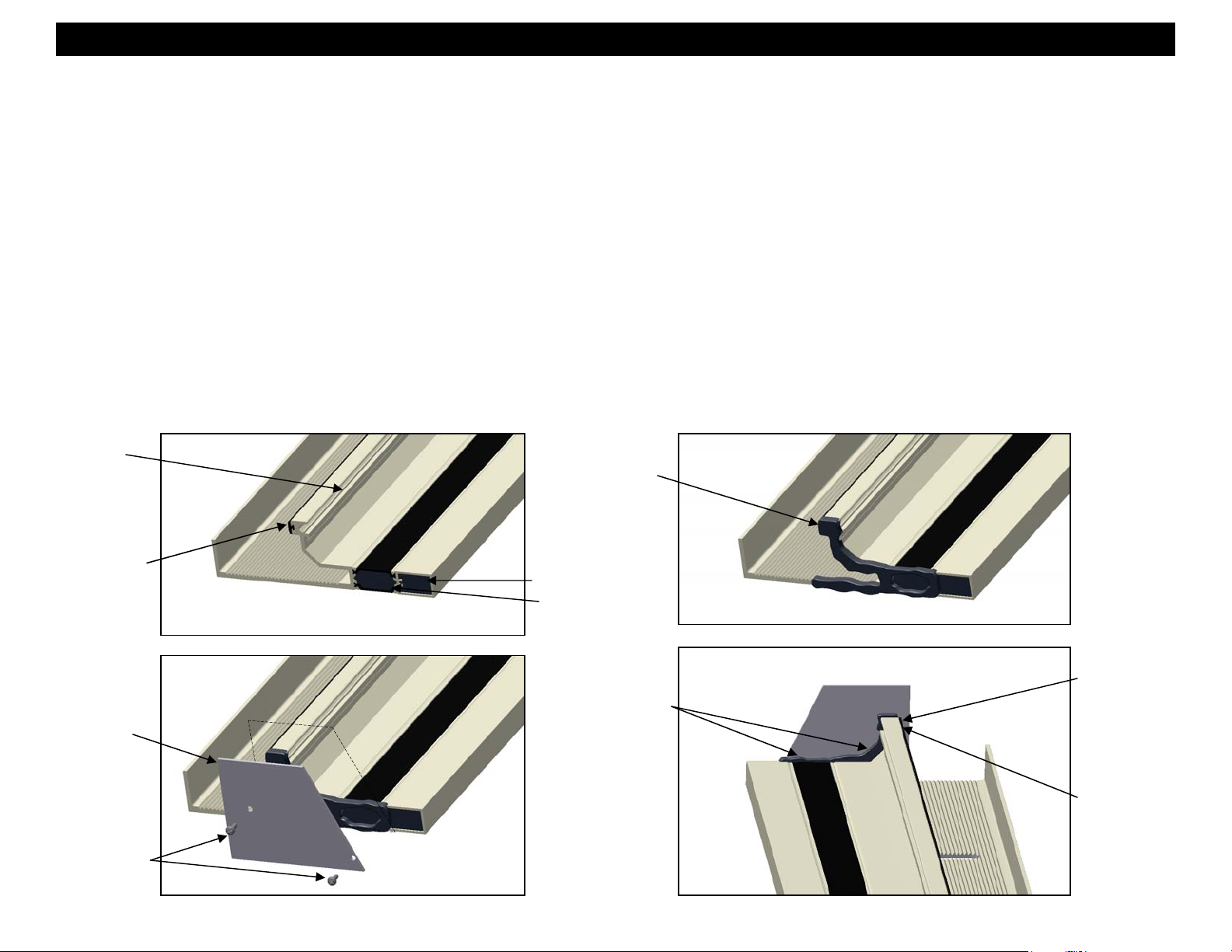
1. Preparation of the Static Starter Sill:
a. The static starter sill may have an end dam pre-attached and sealed at the jamb condition. Ensure that the end dam is properly applied and sealed
to the starter sill as described below. This is a critical seal and the joint must be carefully tooled to create a watertight seal. See Figures 1, 2, 3 & 4.
b. The starter sill may have LC23 spacer pre-applied. The LC23 is cut to the length of the starter sill. The WEA2 gasket will not be applied at this point,
it will be applied once all sections of the sill are set to avoid having seams or splices. This will be covered later in these instructions.
c. Plug the both ends of the tubular section of the starter sill by recessing backer rod at least 1” into the end of the tube. Fill the voids in the tube and
between the thermal struts with sealant and tool smooth.
Clean all sealant contact surfaces using an approved solvent or cleaner of all oils and other contaminants. The sealant manufacturer’s
preparation and application instructions should be followed exactly. If sealant primer is required, apply it per the primer/sealant
manufacturer’s instructions.
Pocket for
WEA2
LC23
Spacer
FM56 End Dam
Attach with
(2) STC7
STC7
Figure 1
Silicone Sealant
along profile to be
covered by end
dam
Plug with backer
rod and fill the
voids in the tube
and between the
thermal struts
with sealant and
tool sealant
Tool sealant smooth
into joints.
Figure 3 Figure 4
Figure 2
Ensure LC23
Butts into the
end dam
fully.
Back Seal
End Dam to
Starter Sill
EFCO 2012 Page 12
Page 13
Series 8750XD Unitized Curtain Wall Installation Instructions
Section 3 - Static Starter Sill Preparation and Installation
d. A static loading clip (FM45) is required at each jamb and intermediate vertical. Two are required at corner mullion conditions (FM46 and FM47). The
anchors are used to transfer end load reactions from the verticals into the anchoring syste m . Before installation of the static starter sill, slide the
appropriate number of static loading clips into each section of starter sill. See Figures 5 and 6.
e. Slide the static loading clips into final position before the starter sill anchor bolts have been applied.
Slide static loading clips into
the static starter sill at corners.
(Left hand-FM46, Right handFM47)
Figure 5
Slide FM45 static
loading clips into
the static starter sill.
Plug with backer rod and
fill the voids in the tube
and between the thermal
struts with sealant and
tool sealant smooth.
46° Cut at Corner
Figure 6
EFCO 2012 Page 13
Page 14

Series 8750XD Unitized Curtain Wall Installation Instructions
Section 3 - Static Starter Sill Preparation and Installation
2. Verify that all job site conditions and accompanying substrates receiving the installation are in tolerance and are in accordance with the contract documents.
3. Pre-cleaning the substrates where the caulk joints will be applied later may be advisable prior to setting the starter sill. Final cleaning and sealant primer
application where required should be performed only immediately before caulk joint sealant applicatio n.
4. Use established bench marks to ensure the accuracy of the starter sill location. Precise measurements and coordination with regard to established bench
marks are critical to ensure that the starter sills are installed in the correct location. Improperly installed, or miss-located starter sill s will cause significant
problems for the remainder of the erection process. Align with slab anchors on all floors a bove before unit installation starts. See page 24
5. Refer to the approved shop drawings for type, size, and specific anchor details. Shim the starter sill to the proper elevation height making sure the starter sill
is level. The shims used must be full bearing shims. The shims must fully support the entire load bearing surface of the starter sill at each anchor location.
Refer to the project structural calculation package and final approved shop drawings for detailed information.
6. EFCO recommends minimum of a 1/2” caulk joint between the starter sill and the substrate.
7.
When applying anchor bolts to the starter sill, pre-fabricated serrated washers (FM59 or FM60) must be used. The serrated washers will lock the starter sill
into position when the anchor bolt is tightened. See Figures 7 thru 9. After verifying the final position of the starter sill, secure the anchor bolts as required.
and shop drawings.
Figure 7
Anchor bolts as required.
Static Starter Sill
Serrated Washer
Slide static loading clips in
place before anchoring sill
Apply shims between
starter sill and substrate.
Shim starter
sill to proper
elevation
height.
Pre-fabricated oversized
anchoring slot.
Figure 8
Figure 9
Shim as necessary to
support entire load.
EFCO 2012 Page 14
Page 15

Series 8750XD Unitized Curtain Wall Installation Instructions
Section 3 - Static Starter Sill Preparation and Installation (90° Inside Corner)
8. Using an approved solvent or cleaner, clean the sealant contact surfaces of the corner splice joint of all oils and oth er contaminants.
9. The starter sill will be spliced at corner conditions. Refer to the approved shop dra wing s for p roject specific joint size.
10. Anchor the new starter sill section ensuring the starter sill is level and while maintaining the appropriate joint size at the splice joint.
11. Slide the base anchors into the corner, butting them together.
12. Apply sealant into the joint between the sections of starter sill and tool smooth to create a water tight seal. Use backer rods in the joint where appropriate.
The splice joint width will vary per project requirements. See Figure 11.
13. Apply a bed of sealant over joint then and use pieces cut from HC13 silicone splice sheet to cover joint. Apply sealant around the edges and seams of the
pieces cut from the splices sheet. See Figures 12 and 13.
Figure 11
Static Starter Sill
Serrated Washer
Slide base anchors into
final position before
securing anchors.
90° Inside Corner
Back seal down leg
Butt Joint Typical
Shim starter sill to
proper elevation
height.
Figure 10
Pieces of Silicone
Splice Sheet (2)
Bed of sealant
Figure 12 Figure 13
Anchor bolts as required.
Seal over all
edges of
splice sheets.
Sealant
Seal over all
seams between
splice sheets.
EFCO 2012 Page 15
Page 16

Series 8750XD Unitized Curtain Wall Installation Instructions
Section 3 - Static Starter Sill Preparation and Installation (Splices)
14. Using an approved solvent or cleaner, clean the sealant contact surfaces shown below of all oils and other contaminants.
15. The starter sill should be spliced per the shop drawings. Refer to the approved shop drawings for specific locations and conditions.
16. Anchor the starter sill sections ensuring they are level and while maintaining the appropri ate joint size and splice joint.
17. Apply sealant into the joint between the sections of starter sill and tool to create a water tight seal. The splice joint width will vary per project requirements.
See Figure 14.
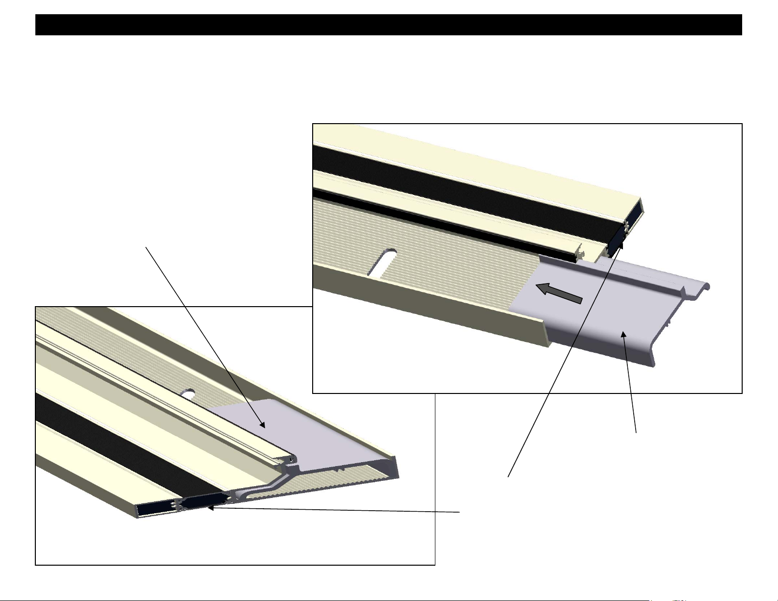
18. Set HC13 or HC14 silicone splice sheet in a bed of sealant centered on the starter sill splice joint as shown in Figures 15 and 16. Force the splice down onto
the gutter, forcing out all air bubbles.
19. Apply sealant around the edges of the splice an tool smooth and water tight. See Figure 16.
Anchor bolts as required.
Static Starter Sill
Figure 14
Figure 15
Back seal down leg
Place splice
sheet HC13 into
a bed of sealant.
Slide splice sheet up
under gasket track and
tool sealant to ensure a
watertight seal.
Apply sealant around
entire perimeter of
splice sheet and tool to
create a watertight seal.
Apply sealant between
the two starter sills
and tool to create a
watertight seal.
Marry the splice
sheet sealant with
the reveal splice
Figure 16
sealant to create a
watertight seal.
EFCO 2012 Page 16
Page 17

Series 8750XD Unitized Curtain Wall Installation Instructions
Section 3 - Static Starter Sill Preparation and Installation (90° Outside Corner)
20. Using an approved solvent or cleaner, clean the sealant contact surfaces of the corner splice joint of all oils and other contaminants.
21. The starter sill will be spliced at corner conditions. Refer to the approved shop drawings for project specific joint size.
22. Anchor the new starter sill section ensuring the starter sill is level and while maintaining the appropriate joint size at the splice joint.
23. Slide the static loading clips into the corner, butting them together.
24. Apply sealant into the joint between the sections of starter sill and tool smooth to create a water tight seal. Use backer rods in the joint where appropriate.
The splice joint width may vary per project requirements. See Figure 17.
25. Apply a bed of sealant over joint and use pieces cut from HC13 silicone splice sheet cover joint. Apply sealant around the edges and seams of the
pieces cut from the splices sheet. See Figures 18, 19 and 20.
Shim starter sill
to proper
elevation height.
Apply sealant between
the two starter sills
and tool to create a
watertight seal.
Figure 17
Static Starter Sill
Anchor bolts
as required
90° Outside Corner
Place pieces of
splice sheet
HC13 into a bed
of sealant.
Figure 18
Slide splice sheet up
under gasket track and
tool sealant to ensure a
watertight seal.
Butt Joint Typical
Back seal down leg
Marry the splice
sheet sealant with
the reveal splice
sealant to create a
watertight seal.
Pieces of HC13
Splice sheet (2)
Figure 19 Figure 20
Apply sealant around
entire perimeter and
all seams of splice
sheet pieces and tool
to create a watertight
seal.
EFCO 2012 Page 17
Page 18

Series 8750XD Unitized Curtain Wall Installation Instructions
Section 3 - Static Starter Sill Preparation and Installation
26. Finish installing starter sill sections as previously described until the installation is completed.
27. Push Stack Gasket WEA2 into gasket reglet beginning at one jamb condition and continuing to next jamb condition. Gasket should run continuously through
all corners and splices. Ensure that the gasket is not stretched while performing this task. See Figures 21 and 22.
28. Installation of the Static Starter Sill is now complete.
Figure 21
FM45 Static Loading Clips
FM46 and FM47
FM45 Static Loading Clip
FM46 and FM47
Static Starter Sill
Stack Gasket WEA2
Figure 22
EFCO 2012 Page 18
Page 19

Series 8750XD Unitized Curtain Wall Installation Instructions
Section 4 - Dynamic Starter Sill Preparation and Installation
1. Preparation of the Dynamic Starter Sill:
a. The dynamic starter sill may have an end dam pre-attached and sealed at the jamb condition. Ensure that the end dam is properly applied and
sealed to the starter sill as described below. This is a critical seal and the joint must be carefully tooled to create a watertight seal. See Figures 23
thru 27.
b. The starter sill may have LC23 spacer pre-applied. The LC23 is cut to the length of the starter sill. The WEA2 gasket will not be applied at this point
it will be applied once all sections of the sill are set to avoid having unnecessary seams or splices. This will be covered later in these instructions.
c. Plug the both ends of the tubular sections of the starter sill by recessing backer rod at least 1/4” into the end of the tube. Fill the voids in the tube and
between the thermal struts with sealant and tool smooth.
Clean all sealant contact surfaces using an approved solvent or cleaner of all oils and other contaminants. The sealant manufacturer’s
preparation and application instructions should be followed exactly. If sealant primer is required, apply it per the primer/sealant
manufacturer’s instructions.
Figure 23
LC23
Spacer
Pocket for
WEA2
Plug with backer rod
and fill the voids in
the tube and between
the thermal struts
with sealant and tool
sealant smooth.
Figure 26
Figure 24
Silicone Sealant
along profile to be
covered by end
dam
Tool sealant smooth
into joints.
Ensure LC23
Butts into the
end dam
fully.
FM55 End Dam
Attach with
(2) STC7
STC7
Figure 25
Figure 27
EFCO 2012 Page 19
Back Seal
End Dam to
Starter Sill
Page 20

Series 8750XD Unitized Curtain Wall Installation Instructions
Section 4 - Dynamic Starter Sill Preparation and Installation
2. Dynamic loading Clip Assembly:
a. Assemble the dynamic loading clips by attaching the anchor bar to the loading clip base with (6) STB1 fasteners. Anchors may come to the field
preassembled, depending on project requirements. Refer to the final shop drawings for project specifi c information.
b. Offset dynamic loading clips be required at the jamb conditions. Outside and inside corner conditions will require different dynamic loading clips.
Dynamic
loading clip
base
STB1(6)
Mullion
(KV25)
Figure 28
Anchor bar
Right Jamb
(KV28)
Left Jamb
(KV26)
Figure 30
Figure 31
Figure 32
Figure 33
Figure 34
90° Outside
Figure 29
EFCO 2012 Page 20
Corner (KV30)
90° Inside
Corner (KV29)
Page 21

Series 8750XD Unitized Curtain Wall Installation Instructions
Section 4 - Dynamic Starter Sill Preparation and Installation
3. Slide in dynamic loading clips. The dynamic loading clips with the exception of the corner s must be installed before the dynamic starter sill sections are set
and anchored. See Figure 35.
4. Reference pages 14 –18 “Static Starter Sill Installation” for Setting, shimming and anchoring the dynamic starter sill sections. The only difference will be at
the corner conditions as a result of the dynamic loading clips (see step 5).
5. At corner conditions slide corner dynamic loading clip into starter sill section that is already anchored then slide the second starter sill section to it. See
figures 36 and 37.
6. Anchor the second starter sill section ensuring the starter sill is level and while maintaining the appropriate joint size at the splice joint.
7. Reference pages 15 –17 for sealing corners joints and splice joints.
Starter Sill Base
Corner Dynamic
Loading Clip
Dynamic Loading Clip
Starter Sill Base
Anchor bolts as required.
Figure 35
Figure 37
Figure 36
Butt joint typical
Starter Sill Base
Back seal down leg
Figure 38
90° Inside Corner
EFCO 2012 Page 21
Page 22

Series 8750XD Unitized Curtain Wall Installation Instructions
Section 4 - Dynamic Starter Sill Preparation and Installation
8. Finish installing starter sill sections as previously described until the installation is completed.
9. Push Stack Gasket WEA2 into gasket reglet beginning at one jamb condition and continuing to next jamb condition. Gasket should run continuously through
all corners and splices. Ensure that the gasket is not stretched while performing this task. See Figures 39 and 40.
10. Installation of the Dynamic Starter Sill is now complete.
Figure 39
KV25 Mullion
Dynamic
Loading Clip
KV29 Inside
Corner Dynamic
Loading Clip
KV28 Right Hand
Jamb Dynamic
Loading Clip
KV30 Outside
Corner Dynamic
Loading Clip
KV25 Mullion
Dynamic
Loading Clip
Static Starter Sill
Stack Gasket WEA2
Figure 40
EFCO 2012 Page 22
Page 23

Series 8750XD Unitized Curtain Wall Installation Instructions
Section 5 - Intermediate Floor Slab Anchor Installation
1. Set the slab anchors into the opening inserting anchor bolts into the slots in the approximate locations required. Do not use shims between the slab anchor
and the slab. Use bituminous coating or other appropriate primer to separate slab anchor from substrate. Anchors are typically located at the mullion center
line at intermediate locations. Jamb anchor locations vary. Refer to the approved final shop drawings for l ocatio n.
2. Apply flat and lock washers and the serrated washers onto the anchor bolts. Turn the serrated washer so that the teeth don't interlock to simplify anchor
adjustments. Leave the nuts loose enough to allow free movement of the anchor assembly. Once the units are set, and final adjustments are made, turn the
serrated washers so that the teeth interlock and secure the anchor assembly.
3. Refer to the final approved shop drawings or supplemental installation instructions for more inf ormation.
FM61 Slab
Anchor
Figure 41
Anchor bolts as
required.
FM56 or FM60
Serrated Washers
FM61 Slab
Anchor
Figure 42
Turn the serrated washer so that
the teeth don't interlock to
simplify anchor adjustments.
FM63 Slab
Anchor
FM62 Slab
Anchor
Once the units are set, and final
adjustments are made, turn the
washer so that the teeth interlock
and secure anchor bolts.
FM61 Slab
Note:
Bolt size and type specified in the
approved shop drawing must be used.
Figure 44
Anchor
Figure 43
EFCO 2012 Page 23
Page 24

Series 8750XD Unitized Curtain Wall Installation Instructions
Section 5 - Intermediate Floor Slab Anchor Installation
4. Slab anchors on all floors must be aligned with each other and with the started sill.
a. Use established bench marks to ensure the accuracy of the starter sill location and the alignment of the slab anchors. Precise measurement and
coordination with regard to established bench marks are critical to ensure that both the starter sills and slab anchors are installed in the correct
location. Improperly installed or mis-located starter sills or slab anchors will cause significant problems for the remainder of the install.
b. In order to accommodate variation in slab size and location. It is important to place and align all slab anchors before final anchorage of the starter sill.
c. The typical spacing between the front face of the slab anchors and the interior face of the static sill is 1-1/16”. See figure 45 below.
d. The typical spacing between the front face of the slab anchors and the interior face of the dynamic sill is 1”. See figure 46 below.
e. Refer to the final approved shop drawings or supplemental installation instructions for more inf ormation.
Slab Anchor
Slab Anchor
1” Typical
Dynamic Starter Sill
Static Starter Sill
1-1/16”
Typical
Figure 46
Figure 45
EFCO 2012 Page 24
Page 25

Series 8750XD Unitized Curtain Wall Installation Instructions
Section 6 - Unit Inspection and Preparation for Installation
1. Before installing the units, follow this checklist to ensure they are ready for installation:
a. Inspect the units to ensure that each unit has all external gaskets and screws
Verify these gaskets have been crimped securely to the frame. Always check for proper crimping and for missing ga skets.
b. Using an approved solvent or cleaner, clean the vertical and horizontal stack gaskets of all oils and other contaminants ( LC23, LC54,
WC21 and WA02).
c. Mullion plugs are required at the head. Also plugs are required at the head end of the captured system at the end of the Duracast verticals. The
mullion plugs are shop applied and sealed in place. Check to ensure the mullion plugs have been properly applied.
d. All front screw spline screws head should be sealed. See figure 49.
. The WA02 and WC21 gaskets will be shop crimped in place.
LC23
spacer
FM41
Hanger
FM40 Split Mullion
Attachment Clip
WNC1 With Sealant
to cover cavity
WA02
LC54 sweep
cut 1/8”
short per
side to allow
weeping
Figure 48
FM41
Hanger
H12C Mull
Plug
Figure 49
FM11
Mullion
Anchor
WC21
Figure 47
Front screw spline
screw heads sealed.
EFCO 2012 Page 25
Page 26

Series 8750XD Unitized Curtain Wall Installation Instructions
Section 6 - Unit Inspection and Preparation for Installation
e. Using an approved solvent or cleaner, clean the sealant contact surfaces of the expansion cavity of the stack sill and jamb of all oils and
other contaminants. See Figure 50.
f. Apply a generous amount of sealant in both ends of the stack cavity approximately 4” to 6” long. See Figure 50.
g. Place the HC05 foam sealant backer into one end of the stack cavity with approximately 4” extending out of the cavity at split mullion and about 1/2”
extending from the face at jamb. The HC05 foam sealant backer should be applied to the jamb or split mullion half where the backer will be exposed
after the frame has been set. See Figure 50. The HC05 will be applied at both side of the jamb condition unit on each row. All sequential units will
get sealant on both side but will only get one HC05. These units will get the HC05 in the side opposing the previous unit.
h. Generously apply sealant to surface of he HC05 that will contact the stack leg of the sill or unit below. This should be done just before the units is set.
i. Apply a continuous bead of sealant up the entire split mull on the along the WC21 gasket and the adjacent snap leg (top to bottom). See figure 51.
Clean the cavity at
SILL
Split
Mullion
Half
4”
the sill approximately
6” to 8“ from each
end. Apply a
generous amount of
sealant about 4” to 6”
into the cavity.
Split
Mullion
Half
Apply a continuous
bead of sealant up
the split mull along
the WC21 gasket.
Apply a generous
bead of sealant to
the length of the
HC05 foam backer.
Weep area.
Push the HC05 foam backer into
the cavity so that it forces the
sealant into all corners of the
cavity to ensure a watertight
seal at unit installation.
Figure 51 Figure 50
SILL
EFCO 2012 Page 26
Weep area.
Page 27

Series 8750XD Unitized Curtain Wall Installation Instructions
Section 6 - Unit Inspection and Preparation for Installation
2. Preparations are different at the jamb condition units.
a. Apply backer rod and sealant into the hollows of the jamb adapter.
b. Apply a splice sheet following steps 2-6 on page 33. See figure 52. Note: steps a & b can be done before or after the unit is set. Steps c thru e must
be done immediately before the unit above is set.
c. Apply HC05 sealant backer per instructions on page 26. See figure 53. Note that the HC05 only needs to extend slightly past the face of the mull.
d. A splice sheet will be applied the condition side of the unit to act as an end dam. There is a special splice sheet for this application with double stick
tape on one end. (KV39) Use this tape to attach the splice sheet to the unit. See figure 54.
e. Apply sealant to the side of the splice sheet that is hanging this will be used to seal it to the unit below. See figure 54.
f. Once the unit is completely set press the hanging end of the splice sheet to the unit below and smooth to remove any bubbles. See figure 55.
g. Finally liberally apply sealant around the perimeter of the splice sheet. See Figure 55.
Figure 52
WEA2 Stack Gasket
Splice sheet set
and bed of sealant
and edge sealed.
Figure 54
HC05
Extending
Slightly
Figure 55
Apply sealant
to the HC05.
Figure 53
LC54 to be cut 1/4”
short to allow
weeping.
Sealant around
perimeter of sheet
Use double stick
Apply sealant to
the free end of
the splice sheet,
to be stuck to the
unit below.
tape to apply
HC13 or HC14 Silicone
Splice Sleeve, leave
edge hanging
Press free end of
sheet to the unit
below once it is
completely set.
EFCO 2012 Page 27
Condition
removed to
allow process
to be seen
better.
Note Jamb
Page 28

Series 8750XD Unitized Curtain Wall Installation Instructions
Section 7 - Setting Units at Static Starter Sills
1. Static starter sills are used with installations that don’t require provisions for vertical movements at the beginning floor of the curtain wall.
2. Ensure that end dam is properly sealed and apply a bead sealant to top of stack leg about 8” long where HC05 foam sealant backer will contact it.
3. Units are typically installed from left to right from as seen from the exterior of the building. Install each frame unit in sequence, starting at the left jamb unit.
4. Units are lifted by the splice bars attached at the head of each unit. These bars are also used to align the units when stacked vertically.
5. Lower the jamb unit down into position onto the starter sill. The hook anchors should also be hooked onto the slab anchors. The unit should now be setting
hard on the starter sill. See Figures 56 and 58.
6. If the starter sill was properly installed and the unit is square and is setting hard on the starter sill, the unit will be at the proper elevation and will be level and
plumb from side to side.
7. Compare the jamb unit to established bench marks and move the unit side to side to position it laterally to the final required location.
8. Adjust the unit for plumb, parallel to the plane of the wall, by sliding the slab anchor forward or backward until the unit is plumb. See Figure 57.
9. Rotate the serrated washers where the serrations align with the serrations in the anchor and secure the slab anchor’s anchor bolts. See Page 23 Figure 43.
Match drill the slab anchors through the hook anchors on both sides of the unit, and install the pinning screw to lock the frame unit into the final position. See
Figure 58.
Splice Bar
Jamb Unit
lift point
Once final adjustments
have been made, match
drill the hook anchor and
install the M171 pin screw
to lock the lateral position
of the frame unit.
Mullion Anchor
Sealant
Once the units are set
and final adjustments
are made, turn the
washer so that the
Static Starter Sill
Figure 56
Figure 57
serrations align and
secure anchor bolts.
EFCO 2012 Page 28
Figure 58
Page 29

Series 8750XD Unitized Curtain Wall Installation Instructions
Section 7 - Setting Units at Static Starter Sills
10. Before setting the next unit apply a generous amount of sealant to the foam sealant backer. Run a bead down the entire length . See Figure 59.
11. Set the next unit after the jamb unit by nesting the vertical stacking mullions together without snapping them. See Figure 61.
12. Lower the unit to the static starter sill, but still be approximately 1/2” above the engagement leg of the starter sill. The unit hook anchors should have enough
vertical adjustment to hook onto the slab anchors.
Figure 59
Apply sealant
to foam backer
Figure 60
Once unit is approximately 1/2”
above engagement leg of stack
sill, snap mullions together.
Mate mullions without snapping them
together before setting on the starter
sill, then lower unit to with 1/2” of the
starter sill engagement leg.
Figure 61
1/2”
EFCO 2012 Page 29
Figure 62
Page 30

Series 8750XD Unitized Curtain Wall Installation Instructions
Section 7 - Setting Units at Static Starter Sills
13. Once the unit is approximately 1/2” above the engagement leg of the starter sill, use clamps to snap the mullions together. Place one clamp at the center of
the mullion at the bottom of the units. Use wood blocks to protect the finished surfaces of the mullions. Tighten the clamp until the mullion halves begin to
snap together. Place another set of wood blocks and a clamp a couple of feet up the unit mullions and tighten it until the mullions snap together. Repeat this
process up the length of the mullion until the mullion halves are snapped together continuously. It may be necessary to work from one clamp to the next
several times, or move the clamps to ensure the mullions are snapped together evenly. See Figure 63.
14. Lower the unit the rest of the way down until it sets hard on the static starter sill.
15. Slide the unit laterally to adjust the mullion width to 3”. This will allow 1/8” for expansion at each mullion.
16. Adjust the free end of the unit for plumb, parallel to the plane of the wall, by sliding the slab anchor forward or backward until the unit is plumb.
17. Rotate the serrated washers where the serrations align with the serrations in the anchor and secure the slab anchor’s anchor bolts.
18. Match drill the slab anchors through the hook anchors on both sides of the unit, and install the pinning screws to lock the frame unit into the final position.
See Figures 64 and 65.
19. Repeat steps 10 through 18 until all units on the static starter sill level have been installed.
20. When erecting a long run of units, check overall frame location dimensions at every fifth unit to avoid dimensional buildup and to ensure that units are
properly positioned with regard to established bench marks.
21. Proceed to “Section 9 - Applying Critical Seals and Stack Gasket”.
Once final adjustments have
been made, match drill the
hook anchor and install the
pin screw to lock the lateral
position of the frame unit.
Clamp
mullions
and snap
together.
Wood block
on both sides
of mullion.
Figure 63
Once the units are set and
final adjustments are made,
turn the washer so that the
serrations align and secure
anchor bolts.
Figure 64 Figure 65
EFCO 2012 Page 30
Page 31

Series 8750XD Unitized Curtain Wall Installation Instructions
Section 8 - Setting Units at Dynamic Starter Sills
1. Dynamic starter sills are used with installations that require provisions for vertical movements at the beginning floor of the curtain wall.
2. Setting unit units at the dynamic starter sill is very similar to setting units at the static starter sill. There are however a few differences. These differences are
explained verbally and graphically below. Also reference pages 26 through 28 “Setting Units at Static Starter Sills”.
3. Place temporary 3/4” shims between the unit sill and the front of the dynamic starter sill. The shims are used to maintain the correct spacing at the stack joint
area of the starter sill. See Figures 66 and 67.
4. Lower the jamb unit down into position while inserting the dynamic load clip (FM48) and stacking the unit onto the starter sill. The hook anchors should also
be hooked onto the slab anchors. The unit should now be setting hard on the shims.
5. Reference page 28 steps 6-8 for plumbing unit and fastening slab anchors.
6. Tighten the jack bolts of the mullion anchors just tight enough so that the shims can be removed and the unit stays in the nominal positi on. Remove the
shims between the sill and the starter sill that were applied in step 3.
7. Set the unit to the required elevation height and level it by turning the jack bolt at each mullion anchor clockwise to raise, or counterclockwise to lower the unit
in to the final position.
8. Match drill the slab anchors through the hook anchors on both sides of the unit, and install the pinning screws to lock the frame unit into the final position.
See Figure 58 on page 28.
Jamb Unit
Adjust the jack bolt as required
for the unit to set hard on the
shim pack at the stack joint
below. Rotate the bolt clockwise
to raise or counterclockwise to
lower the unit.
Dynamic
load clip
Sealant
3/4” shim pack
3/4” shim pack
Dynamic Starter Sill
Figure 66 Figure 68 Figure 67
placed between
the starter sill
and the unit sill.
placed between the
starter sill and the
unit sill.
Once the units are set and final
adjustments are made, turn the
washer so that the serrations
align and secure anchor bolts.
Splice Bar
lift point
EFCO 2012 Page 31
Page 32

Series 8750XD Unitized Curtain Wall Installation Instructions
Section 8 - Setting Units at Dynamic Starter Sills
9. Before setting the next unit adjust the dynamic loading clip so that it aligns with the vertical. The anchor can be slid from side to side on the insert.
10. Next apply a generous amount of sealant to the foam sealant backer. Run a bead down the entire length. See Figure 69.
11. Set the next unit after the jamb unit by nesting the vertical stacking mullions together without snapping them. See Figure 61 on page 29.
12. Lower the units enough to engage the slab anchor bar (FM48) at the sill, but still be approximately 1/2” above the engagement leg of the starter sill. The unit
hook anchors should have enough vertical adjustment to hook onto the slab anchors. Reference page 29.
13. Place temporary 3/4” shims between the unit sill and the front of the dynamic starter sill.
14. Once the unit is approximately 1/2” above the engagement leg of the starter sill, use clamps to snap the mullions together. Reference Figure 63 and step 13
on page 30. See also Figure 72 below.
15. Lower the unit down into position to completely engage the anchor bars (FM48) and the unit sets hard on the shims between the unit sill and the dynamic
starter sill. The hook anchors should also be hooked onto the slab anchors.
16. Adjust the jack bolt as required for the unit to set hard on the shim pack at the starter sill below.
17. Reference steps 15-17 on page 30 for adjusting and plumbing, then fastening sl ab anchors
18. Tighten the jack bolts of the mullion anchors just tight enough so that the shims at the starter sill below can be removed and the unit stays in the nominal
position. Remove the shims between the sill and the starter sill that were applied in step 13.
18. Set the unit to the required elevation height and level it by turning the jack bolt at each mullion anchor clockwise to raise, or counterclockwise to lower the unit
in to the final position.
19. Match drill the slab anchors through the hook anchors on both sides of the unit, and install the pinning screws to lock the frame unit into the final position.
20. Repeat steps 9 through 20 until all units on the dynamic starter sill level have been installed.
21. When erecting a long run of units, check overall frame location dimensions at every fifth unit to avoid dimensional buildup and to ensure that units are
properly positioned with regard to established bench marks.
22. Proceed to “Section 9 - Applying Critical Seals and Stack Gasket”.
Sealant
Adjust dynamic
loading clip by
sliding side to
side.
Figure 69 Figure 70 Figure 71 Figure 72
Shim
EFCO 2012 Page 32
Page 33

Series 8750XD Unitized Curtain Wall Installation Instructions
Section 9 - Applying Critical Seals and Stack Gasket
1. Once a complete row of units has been installed the WEA2 stack gasket must be applied from the roll to avoid unnece ssary splicing. See Figures 73 and 74.
2. A splice is also required at the gutter at the top of the units, before units are stacked on top of them. Clean the gutter sill sealant contact surfaces using
an approved solvent or cleaner of all oils and other contaminants where the gutter splice will be applied. The sealant manufacturer’s preparation
and application instructions should be followed exactly. If sealant primer is required, apply it per the primer/sealant manufacturer’s instructions.
3. Apply a bed of sealant on the gutter that will cover the area where the splice sheet (HC13 or HC14) will be applied. When creating the bed of sealant, apply
a generous amount of sealant directly on top of the primary seal location as shown in Figure 74.
4. The sealant must go from the front of the gutter up the engagement leg to the WEA2 gasket track. The sealant bed must be wide enough to cover the entire
area of the gutter splice. See Figure 74.
5. Lay the gutter splice into the bed of sealant. Press the gutter splice up under the WEA2 gasket track. See Figure 75. Smooth the splice down onto the
gutter, forcing out all air bubbles.
6. Apply sealant around the perimeter of the gutter splice. Tool the sealant to ensure a watertight seal at the splice. See Figure 76.
7. Apply sealant in the gap between the two snap in legs for the WEA2 gasket, across the top of the engagement leg and down the back leg. Tool the sealant
into all voids to ensure a watertight seal. See Figure 76.
Figure 73 Figure 74
Figure 75
WEA2 Stack Gasket
HC13 or HC14 Silicone
Splice Sleeve
Create a bed of
sealant to lay the
gutter splice into.
Apply sealant around
the entire perimeter of
the gutter splice and
tool to create a
watertight seal.
Figure 76
WEA2 Stack Gasket
Back seal
down leg.
Apply sealant between
the engagement legs
of the two units. Tool
sealant to create a
watertight seal.
EFCO 2012 Page 33
Page 34

Series 8750XD Unitized Curtain Wall Installation Instructions
Section 10 - Setting Typical Intermediate Units
1. Install each frame unit in sequence, starting at the left jamb unit.
2. Lift the jamb unit with the splice bars at the head of the unit.
3. Ensure the HC05 caulk backer has been inserted into the sill as shown in Figure 50 on page 26. Note that jamb units will receive HC05 on both ends of the
sill. Subsequent units will require HC05 on the right end only of the unit sill as viewed from the exterior.
4. When stacking units vertically, place a temporary 1” shim between the units as shown in Figure 77. The shims are used to hold the unit in the nominal
installed position.
5. Lower the jamb unit down into position to engage the unit hanger load clips (FM41) at the stack joint. The hook anchors should also be hooke d onto the slab
anchor. (See Figure 58 on page 28) The unit should now be setting hard on the shims.
6. The final adjustment and setting of a typical intermediate jamb condition unit is the same as the final adjustment and setting at sill units. See steps 5-8 on
page 31 for adjustment and final setting of the unit.
Adjust the jack bolt as
required for the unit to set
hard on the shim pack at the
Jamb Unit
stack joint below. Rotate the
bolt clockwise to raise or
counterclockwise to lower
the unit.
Splice sheet
applied before
setting unit.
See page 26
Splice Bar
Sealant
Jamb Unit
1” shim pack placed
around the splice bar on
top of the mullion at the
head of the unit below.
HC05 caulk backer
Once the units are set and final
adjustments are made, remove the
shim by tightening the jack bolts
EFCO 2012 Page 34
Figure 78 Figure 77
Page 35

Series 8750XD Unitized Curtain Wall Installation Instructions
Section 10 - Setting Typical Intermediate Units
7. Before setting the next unit apply a generous amount of sealant to the foam sealant backer. Run a bead down the entire length. See Figure 79.
8. Set the next unit after the jamb by nesting the vertical stacking mullions together without snapping them. See Figure 61 On page 29.
9. Lower the units enough to engage the unit splice bar (FM41) at the sill but still be approximately 1/2” above the engagement leg of the starter sill. The unit
hook anchors should have enough vertical adjustment to hook onto the slab anchors.
10. Place a 1” shim pack around the hanger load clip on top of the mullion at the head of the unit below. See Figure 89.
11. Once the unit is approximately 1/2” above the engagement leg of the gutter at the stack joint, use clamps to snap the mullions together. Reference Figure 63
and step 13 on page 30.
12. Lower the unit down into position to completely engage the unit splice bars at the stack joint. The hook anchors should also be hoo ked onto the slab anchor.
The unit should now be setting hard on the shims.
13. Adjust the jack bolt as required for the unit to set hard on the shim pack at the starter sill below.
14. The final adjustment and setting of a typical intermediate unit is the same as the final adjustment and setting at sill units. See steps 5-8 on page 31 for
adjustment and final setting of the unit.
15. Repeat steps 2 through 14 until all units on the intermediate floor levels have been installed.
16. When erecting a long run of units, check overall frame dimensions at every fifth unit to avoid dimensional buildup and to ensure that units are properly
positioned with regard to established bench marks.
Figure 79 Figure 80
Apply sealant
to foam backer
Figure 82
1/2”
Once unit is approximately 1/2”
above engagement leg of stack
sill, snap mullions together.
Place 1” shim around the splice
Figure 81
bars on top of the mullion at the
head of the unit below
EFCO 2012 Page 35
Page 36

Series 8750XD Unitized Curtain Wall Installation Instructions
Section 11 - Setting Typical Head Condition Units
1. Setting typical head condition units is very similar to setting typical intermediate units. Reference paged 34 and 35. There are however a few differences
these will be explained verbally and graphically below.
2. Apply splice sheet to the top corners per steps a & b on page 27, leaving a portion of the slice sheet hanging over the edge. Apply sealant to the underside
of the portion hanging over the edge, and wrap it down over the edge. Smooth it to remove any bubbles in the sealant. Apply sealant to the edge and tool to
create a water tight seal. See figures 83 thru 86.
3. The typical head condition units have an optional retractable hanger (KV20), which can be drive down with a mallet to get it out of the way for setting the unit.
See figures 86 and 87.
Figure 83
Screw hole to
be plugged
and sealed
Apply sealant to
the edges of the
splice sheet and
tool to create a
water tight seal.
Apply backer rod
and sealant in
the hollow of the
jamb adapter
Figure 84
Set splice sheet in
a bead of sealant
Apply sealant to
the underneath
side of the splice
sheet that hangs
over the edge
Figure 85
Retractable hanger
can be driven down
with a mallet.
Wrap splice
sheet down over
the edge of the
unit and smooth
top remove any
Figure 86 Figure 87
air bubbles
EFCO 2012 Page 36
Page 37

Series 8750XD Unitized Curtain Wall Installation Instructions
Section 12 - Setting Corner Units
1. Follow the check list in “Section 6 - Unit Inspection and Preparation for Installation” on pages 2 5, 26 and 27 before installing the corner units.
2. Verify the adjacent unit has been installed properly before installing corner units. If not make necessary adjustments to align the units.
3. Corner units are designed to be installed from left to the right as viewed from the exterior of the building.
4. Setting Inside and Outside corner units is very similar to setting typical units at both static and dynamic sills and typical intermediate units. Reference the
corresponding section that applies for detailed instructions. Section 7 “Setting Units at Static Starter Sills” pages 28-30, Section 8 “Setting Units at Dynamic
Starter Sills” pages 31-32, Section 10 “Setting Typical intermediate Units” pages 34-35, and Section 11 “Setting Typical Head Condition Units” page 36.
5. The exception being inside corners. The unit on the left (viewed from the exterior) will have the right edge of the unit coming in without a cover or duracast
spacer. This is designed to come together with the left edge of the unit on the right. Before setting the left unit the HD26 Joint plugs will need to be sealed.
See shop drawings for more detail.
90 degree inside corner
at dynamic starter sill
viewed from interior
Clamp
mullions
and snap
together.
Place 1” shim around the splice
bars on top of the mullion at the
head of the unit below
Wood block
on both sides
of mullion.
Figure 89
90 degree outside corner
at typical intermediate
viewed from interior
Figure 88 Figure 90
EFCO 2012 Page 37
90 degree
inside corner
at dynamic
starter sill
viewed from
interior
Page 38

Series 8750XD Unitized Curtain Wall Installation Instructions
Section 13 - Applying Typical Perimeter Seals
1. The typical head, jamb and starter sill are as shown below. The caulk joint size is job specific, below a 1” caulk joint is shown at head and jambs and a 1/2”
caulk joint at the sill. All seals should join each other head and sill seals should join verticals.
2. The condition at the head is job specific. See Figure 91 for a typical generic head sealant detail. See shop drawings of job specific details.
3. The line of sealant at the jamb will follow the front edge of the back member. See Figure 92. Special care is needed to ensure that the end dam is properly
sealed and marries into the perimeter sealant correctly at the jamb to sill condition. See Figures 94.
4. At jamb conditions of the unit stack joint, a splice sheet has been applied. Special care is needed to ensure the splice sheet is properly sealed and marries
into the perimeter sealant correctly. See Figure 95.
5. The caulk joint at the starter sill is located at the exterior part of the starter sill and must return at the jambs to marry with the perimeter caulking of the jambs.
Backer Rod and
Perimeter Seal
Backer Rod and
Perimeter Seal
Backer Rod and
Perimeter Seal
Figure 91 Figure 92
Note:
Jamb condition not
shown for clarity.
Note:
Jamb condition not
shown for clarity.
Marry jamb
sealant line to
sill sealant line.
Figure 94 Figure 95
Marry jamb sealant
line with splice
sheet sealant
EFCO 2012 Page 38
Figure 93
Page 39

Series 8750XD Unitized Curtain Wall Installation Instructions
Section 14 - Deglaze / Re-glaze Procedures - Captured System
1. The captured system units can be structural silicone glazed to the frame or may be dry glazed. The deglaze and re-glaze of the dry glazed system should be
very straight forward and will be similar to the captured structural silicone glazing instructions below; minus the structural and sealant and using WSD2
interior gasket in place if WC18 spacer. The deglaze and re-glaze procedure must be performed from a swing stage or man lift from the exterior of the
building. Follow the sealant manufacture’s sealant application instruction for deglazing and re-glazing. When deglazing an opening or ope nings at a
captured unit, follow these instructions:
a. Remove the wedge gaskets from the perimeter of the day-lite opening of the lite to be deglazed.
b. Remove the glazing beads, setting blocks, and side blocks from around the opening.
c. Using tools, such as automotive deglazing tools, cut though the glazing sealant removing glazing, old gasket and sealant from the opening. Some
areas may be accessible from the interior.
d. Cut away the sealant from the substrate, leaving a thin film (approximately 1/32” thick) of sealant on the frame. Do not damage the surface finish of
the substrate. Alternatively, if the remaining sealant exhibits adhesive failure, completely remove all sealant, but take care not to damage the
substrate finish.
e. Remove all remaining gasket pieces or sealant residue from inside the gasket reglets.
Note:
It may be necessary to remove
gasket and or bead from lites
above or below the deglazing area.
Cut completely
Remove gaskets
and glazing beads
from the opening of
lite to be deglazed.
through the sealant
joint and remove the
sealant and gaskets.
Cut completely
through the sealant
joint and remove the
sealant and gaskets.
Remove gaskets and glazing
beads from the opening of
lite to be deglazed.
Figure 97
Remove setting
and side blocks
from the opening of
lite to be deglazed.
Figure 96
EFCO 2012 Page 39
Page 40

Series 8750XD Unitized Curtain Wall Installation Instructions
Section 14 - Deglaze / Re-glaze Procedures - Captured System
2. When re-glazing an opening or openings at a captured unit, follow these instructions:
a. Using an approved solvent or cleaner, clean the glazing surfaces of all oils and other contaminants. The sealant manufacturer’s
preparation and application instructions should be followed exactly. Fresh sealant will adhere to cured sealant without primer. Primer may be
necessary if the sealant has been completely removed.
b. Replace WC18 preset spacer gasket with new gasket around the entire opening. Ensure the gaskets are firmly butted together in the corners.
c. Run a bead of sealant around the WC18 gasket as shown below. The joint must be filled with sealant in excess so that it will fill all voids between the
glazing and the WC18 gasket when the glazing is put in place. Tool the sealant into a beveled shape as shown b elow prior to setting the glazing.
Ensure no voids or air bubbles are present in the sealant. The glazing must be set within 10 minutes or before the sealant begins to skin over.
d. Carefully insert new setting blocks in the locations as noted in the approved shop drawings.
e. Clean the new glass or panel and set it in place, centered in the opening, setting on the setting blocks. Do not contaminate the sealant contact
surfaces of the glazing during handling. Press the glazing firmly against the spacer gaskets. Avoid sliding the glazing around on the spacers, as this
can force sealant into visible areas seen from the interior.
f. Apply temporary retainers with wedge gaskets (WC22) at quarter points of the D.L.O. on all four sides of the opening.
g. Tool the sealant around the perimeter of the glazing, packing the sealant into the joint, to ensure any voids or air bubbles in the sealant are
eliminated. Carefully relocate the glazing retainers to expose inaccessible areas behind the retainer, and tool the sealant at those areas. Pay
particular attention at the corners of the glazing.
h. Remove and replace the temporary retainers with a cover and gasket (WC22) join one side of the glazing at a time. Replace one side, and then
replace the opposing side next. Replace the remaining sides last. If the exterior gaskets were damaged when they were removed, replace them with
new gaskets.
Remove and replace the
temporary retainers with a
cover and gasket.
WC22 Gasket
Apply sealant
around the opening
and tool as shown.
Note:
Only silicone sealants which
have been developed and
tested specifically for
structural glazing
applications should be used
for re-glazing purposes.
Apply new WC18
spacer gaskets.
WC18 Gasket
High modulus
silicone sealant.
Figure 98 Figure 99
Set the glazing in
place, pressing the
glazing firmly against
the spacer gaskets.
Apply t emporary
retainers with wedge
gaskets at quarter
points of the D.L.O.
WC22 Gasket
Tool the sealant
around the perimeter
of the glazing.
Remove and replace the
temporary retainers with a
cover and gasket.
Tool the sealant
around the perimeter
of the glazing.
Remove and replace the
temporary retainers with a
cover and gasket.
EFCO 2012 Page 40
Page 41

Series 8750XD Unitized Curtain Wall Installation Instructions
Section 15 - Deglaze / Re-glaze Procedures - SSG System
1. The deglaze and re-glaze procedure must be performed from a swing stage or man lift from the exterior of the building. Follow the sealant manufacture’s
sealant application instruction for deglazing and re-glazing. When deglazing an opening or o penings at a structural silicone glazed unit follow these
instructions:
a. Cut and remove the weather seal, side blocks and setting blocks, from around the lite of glazing.
b. Using tools, such as automotive deglazing tools, cut though the glazing sealant removing glazing, old gasket and sealant from the opening. Some
areas may be accessible from the interior.
c. Cut away the sealant from the substrate, leaving a thin film (approximately 1/32” thick) of sealant on the frame. Do not damage the surface finish of
the substrate. Alternatively, if the remaining sealant exhibits adhesive failure, completely remove all sealant, but take care not to damage the
substrate finish.
d. Remove all remaining gasket pieces or sealant residue from inside the gasket reglets.
e. Remove LC45 and Cover from verticals.
Cut out and
remove the
weather
seals.
Remove setting
and side blocks
from the opening of
lite to be deglazed.
Cut completely
through the sealant
joint and remove the
sealant and gaskets.
Figure 100
Cut completely
through the sealant
joint and remove the
sealant and gaskets.
Figure 101
Remove setting
and side blocks
from the opening of
lite to be deglazed.
Cut out and remove
the weather seals.
Remove LC45
and cover at
verticals only
EFCO 2012 Page 41
Figure 102
Page 42

Series 8750XD Unitized Curtain Wall Installation Instructions
Section 15 - Deglaze / Re-glaze Procedures - SSG System
2. When re-glazing an opening or openings at a structural silicone glazed, follow these instructions:
a. Using an approved solvent or cleaner, clean the glazing surfaces of all oils and other contaminants. The sealant manufacturer’s
preparation and application instructions should be followed exactly. Fresh sealant will adhere to cured sealant without primer. Primer may be
necessary if the sealant has been completely removed.
b. Replace WC18 preset spacer gasket with new gasket around the entire opening. Ensure the gaskets are firmly butted together in the corners.
c. Run a bead of sealant around the WC18 gasket as shown below. The joint must be filled with sealant in excess so that it will fill all voids between the
glazing and the WC18 gasket when the glazing is put in place. Tool the sealant into a beveled shape as shown b elow prior to setting the glazing.
Ensure no voids or air bubbles are present in the sealant. The glazing must be set within 10 minutes or before the sealant begins to skin over.
d. Carefully insert new setting blocks in the locations as noted in the approved shop drawings.
e. Clean the new glass or panel and set it in place, centered in the opening, setting on the setting blocks. Do not contaminate the sealant contact
surfaces of the glazing during handling. Press the glazing firmly against the spacer gaskets. Avoid sliding the glazing around on the spacers, as this
can force sealant into visible areas seen from the interior.
Apply sealant
around the opening
and tool as shown.
Apply new WC18
spacer gaskets.
WC18 Gasket
High modulus
silicone sealant.
Figure 103
Set glass but do
not apply the
exterior weather
seal until the
silicone has
cured.
Figure 104
Note:
Only silicone sealants which have been
developed and tested specifically for
structural glazing applications should
be used for re-glazing purposes.
EFCO 2012 Page 42
Page 43

Series 8750XD Unitized Curtain Wall Installation Instructions
Section 15 - Deglaze / Re-glaze Procedures - SSG System
e. Apply temporary retainers at verticals. Temporary retainers will be comprised of FM38, 4” pieces of 17T2 and WC22 gasket. If there is captured
glazed system on the job used scraps for this. If there is none available then the materials for these temporary retainers must be ordered.
g. Tool the sealant around the perimeter of the glazing, packing the sealant into the joint, to ensure any voids or air bubbles in the sealant are
eliminated.
h. Once the structural silicone cures remove the temporary glazing retainers, and replace with LC45 with cover.
i. Do not apply the weather seal around the perimeter of the glazing until the structural silicone joint cures. The SSG joint will typically take 7-14 days,
but it can take up to 28 days to fully cure depending on temperature and humidity. Consultation with the sealant manufacturer is recommended.
j. When the structural silicone joints are fully cured, remove the temporary retainers. Properly clean and prepare the joints, apply backer rod and the
weather seal. Tool the joint to form an hour glass shaped sealant joint as shown.
Set the glazing
in place,
pressing the
glazing firmly
against the
spacer gaskets.
Do not apply the
exterior weather
Figure 105
seal until the
silicone has
cured.
4” Temporary
glazing
retainer at
jambs. Do
not remove
until sealant
at horizontals
has cured
Figure 106
After silicone
cures remove
temporary
glazing retainers
and replace with
LC45 and cover.
Figure 107
EFCO 2012 Page 43
 Loading...