

Page 1

8
Y
Series 5
00
E-wall silicone gasket curtain wall system
Installation instructions
Part NO.
February 2013
330
Page 2
Minimizing Condensation
Note: Please reference EFCO's "Understanding Condensation" brochure which can be obtained
through your EFCO representative.
Condensation will form on any surface when unfavorable conditions (interiro temperature and
relative humidity and exterior temperature) are present. When the formation of extensive condensation
is a concern, it is highly recommended that a design professional is utilized to perform an analysis of
the shop drawings to recommend the best possible installation methods. Please contact your EFCO
representative for information on EFCO's Thermal Analysis Serv ices.
Many current installation practices lead to an increase in the possibility of the formation of
condensation. Though not all inclusive, the list of examples below illustrates conditions under which
condensation is lik ely to occur:
1. Bridging system thermal break with non-thermally broken metal flashing or lintels that
are exposed to the exterior
2. System exposure to the cold air cavities
3. Interior relative humidity levels not maintained at recommended levels, see EFCO's
"Understanding Condensation" brochure
4. Inadequate separation between system and surrounding condition at perimeter
5. Product conbinations during the shop drawing stage that result in bridging thermal
breaks of one or all products involved
7/2011
Page 3

SECTION I: GENERAL NOTES AND GUIDELINES
PAGE 1
NOTE:
THESE INSTALLATION INSTRUCTIONS ARE A SUPPLEMENT TO
THE APPROVED SHOP DRAWINGS AND MUST BE USED IN
CONJUNCTION WITH THOSE DRAWINGS.
1.
HANDLING/STORING/PROTECTING ALUMINUM - The following precautions
are recommended to assure early acceptance of your products and
workmanship.
A. HANDLE CAREFULLY - Store with adequate separation between com-
ponents so material will not become scratched or rubbed at points
of contact. Store off the ground. Protect against weather elements
and other construction trades in adjacent areas of the job site.
B. KEEP MATERIAL AWAY FROM WATER, MUD, AND SPRAY - Prevent cement,
plaster, and other materials from coming in contact with and
damaging the finish. Do not allow moisture to be trapped between the
finished surface and the wrapping material.
C. PROTECT MATERIALS AFTER ERECTION - Wrap or erect screens of plastic
sheeting. Cement, plaster, terrazzo, and other alkaline materials are
very harmful to the finish and must be removed with water and mild
soap before hardening. Under no circumstances should these
materials be allowed to dry or permanent staining will occur.
GENERAL GUIDELINES - The following practices are recommended for all
2.
installations.
A. REVIEW THE APPROVED SHOP DRAWINGS to become thoroughly familiar
with the project.
B. INSTALL ALL FRAMING MATERIALS PLUMB, LEVEL, AND TRUE - Proper
alignment and relationships to benchmarks and column center lines,
as established by the architectural drawings and the general
contractor, must be maintained.
C. The sequence of erection should be coordinated with the project
superintendent to prevent delays and minimize the risk of material
damage. IF PRESET ANCHORS ARE REQUIRED, COORDINATE
WITH THE GENERAL CONTRACTOR AND SUPERVISE THE LOCATION.
9/2000
Page 4

PAGE 2
SECTION I: GENERAL NOTES AND GUIDELINES CONT.
D. Verify that all job site conditions and accompanying substrates
receiving the installation are in accordance with the contract
documents. If deviations occur, notification must be given IN WRITING
to the general contractor and differences resolved before proceeding
further with the installation in the questionable area.
E. Coat all aluminum, to be placed directly in contact with masonry or
dissimilar materials, with a heavy coating of bituminous primer such
as zinc chromate.
F. Follow EFCO’s framing installation and glazing instructions.
G. Verify the contents of all material shipments upon arrival. Verify
quantities and correct finishes. NOTIFY EFCO IMMEDIATELY OF ANY
DISCREPANCIES OR DAMAGE WHICH MAY HAVE OCCURRED.
H. Throughout these instructions the term SEALANT will appear. For the
purpose of these instructions, sealant is to be defined as follows:
SEALANT - A weather resistant, gunnable, liquid filler which when dry
provides a resilient, flexible air and water seal between similar and
dissimilar materials. All sealant must meet FEDERAL SPECIFICATIONS
TT-S-001543A, TT-S-00230C, and ASTM C 290.
NOTE:
Do not assume compatibility of materials in a glazing system already
exists. Chemical reactions from physical contact of incompatible materials
can adversely affect one or all of the glass or glazing materials. It is
strongly advised that sealant manufacturers conduct compatibility and
adhesion tests in their laboratories using each exact component of the
glazing system (i.e., glass product, structural silicone, aluminum with
painted or anodized finish, setting blocks, glazing tapes, etc.) and
document compatibility or other findings in written test reports. All
frame surfaces should be clean, dry, dust free, and frost free. If a primer
is required, it must be applied to clean surfaces. All perimeter substrate
should be cleaned and properly treated to receive sealant. It is the
responsibility of the installer to follow these guidelines.
TOOLS NEEDED:
1. Dead blow hammer, part #HM46
2. Deglazing tool, part #HM47
3. Brush
4. Cutting tool, do not use box or craft knives.
5. Needle nose pliers
6. Metal spatula
7/2003
Page 5
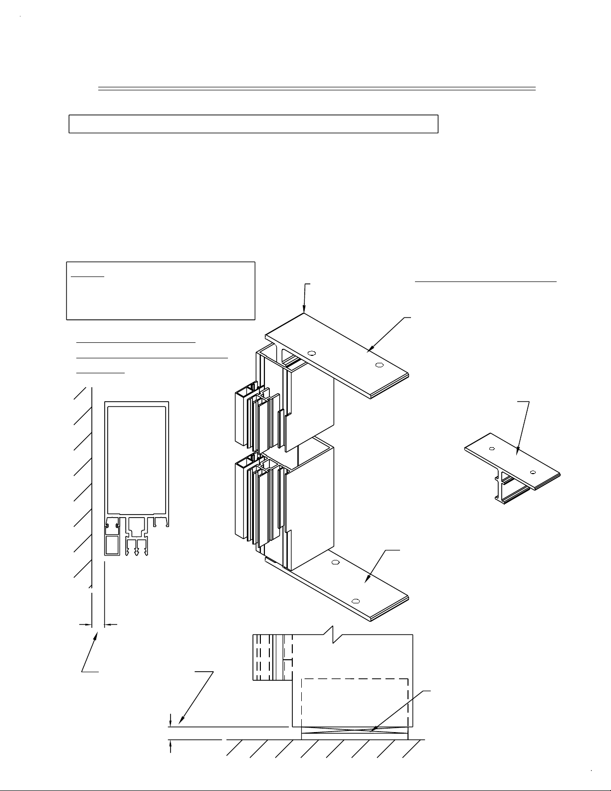
SECTION II: VERTICAL FRAME INSTALLATION
STEP #1 INSTALL VERTICAL MULLIONS AND ANCHORS
Prestage necessary tools and materials in the work area. Prepare all head,
sill, and jamb substrates by cleaning and setting all flashings and/or
membrane seals as specified by the project shop drawings.
Insert the mullion and/or head anchor, as specified by the project
shop drawings, into the end of tubular mullions. For splice joints and floor
anchors at multispan conditions, refer to steps #2 and #3 on pages 4
and 5.
PAGE 3
Note: When attaching pocket
fillers, start at one end and
work into place along the
remaining length.
PERIMETER WITH
CONTINUOUS POCKET
FILLER
"F" ANCHOR
MULLION ANCHORS
TOP ANCHOR IS REQUIRED
AT HEAD CONNECTION
FOR THERMAL MOVEMENT.
MULL ANCHOR AT INTERMEDIATE
VERTICAL MULLIONS.
SIZE AND LOCATE ALL
BOLTS BASED ON JOB
CONDITIONS AND STRUCTURAL
REQUIREMENTS.
SEE APPROVED
SHOP DRAWINGS
FOR DIMENSION.
SHIM UNDER VERTICAL
MULLION.
7/2003
Page 6
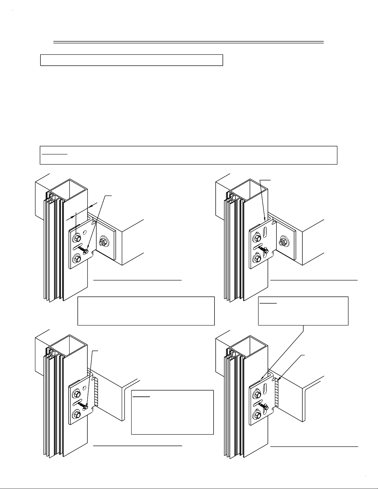
SECTION II: VERTICAL FRAME INSTALLATION
STEP #2 APPLY MIDSPAN FLOOR ANCHORS
Attach the midspan floor anchors to the mullions with temporary alignment
screws. Set the vertical mullion in place, plumb and true. Make permanent
attachment of base anchors, head anchors, and midspan floor anchors to
the building structure as specified in the approved project shop drawings.
After completing permanent anchorage, remove all temporary alignment
screws and fasteners. Multiple runs of vertical mullions can be set in
advance of erecting the horizontal members if desired, or the horizontals can
be filled in as additional mullions are erected.
NOTE: On long runs, check overall frame dimensions at every fifth opening
to avoid dimensional build-up.
POSITION THE MULLION
PLUMB AND TRUE.
PERMANENTLY ATTACH
THE ANCHOR TO THE
STRUCTURE PER PROJECT
SHOP DRAWINGS.
1"
MIN.
TEMPORARY ALIGNMENT
SCREW (REMOVE
AFTER ANCHORING).
PAGE 4
DEAD LOAD ANCHOR
BOLTED TO STRUCTURE
THE FLOOR SLABS MUST BE WITHIN THE
ADJUSTMENT CAPABILITY OF THE ANCHORING
SYSTEM. REFER TO THE PROJECT SHOP
DRAWINGS FOR THE ALLOWABLE ADJUSTMENT.
DRILL THROUGH THE MULLION AT
THE HOLE LOCATION IN THE CLIP
A MINIMUM OF 1" FROM THE
BACK OF THE MULLION.
COMPLETE THE BOLT CONNECTION
PER PROJECT SHOP DRAWINGS.
NOTE: REFER TO PROJECT
SHOP DRAWINGS FOR
WELDING INSTRUCTIONS.
PROTECT THE INSTALLED
GLASS AND METAL FROM
WELD SPLATTER.
DEAD LOAD ANCHOR
WELDED TO STRUCTURE
WIND LOAD ANCHOR
BOLTED TO STRUCTURE
NOTE: USE 1/16" HORSESHOE SHIMS BETWEEN
THE STEEL ANCHORS AND
MULLIONS.
FILLET WELD AT
BOTH SIDES OF
THE ANCHOR.
WIND LOAD ANCHOR
WELDED TO STRUCTURE
9/2000
Page 7

PAGE 5
SECTION II: VERTICAL FRAME INSTALLATION CONT.
STEP #3 INSTALL VERTICAL SPLICE JOINTS
Splice joints should occur at spandrel areas (if possible).
Refer to approved shop drawings for actual locations.
Splice sleeves will be shop assembled in the top of the lower mullion.
GENERAL NOTE: The following details depicts a splice joint of 1/2".
The required joint width must be determined at the design stage and
shown on the approved shop drawings, on a job by job basis.
The actual width of this joint depends on the expected amount of
thermal movement plus the expected movement of the building structure.
Once a final check of expansion joint placement and mullion
position is made, the final match drilling of mullion through anchor
holes and sealing of the splice joint may be completed.
1
2
UPPER MULLION
SPLICE
SLEEVE
SLEEVE
FASTENERS
SHIM UNTIL ALL
ANCHORS ARE
SET IN PLACE,
THEN FACE
SEAL WITH AN
APPROVED SEALANT.
1/2"
SHIM
3
LOWER MULLION
7/2003
Page 8

SECTION III: HORIZONTAL FRAME INSTALLATION
STEP #1 PLUG ENDS OF PERIMETER HORIZONTALS
Prior to horizontal attachment, insert a 2 1/2" piece of backer rod folded to
90 degree into the jamb end of the head and sill horizontals. Seal the ends with
silicone to create an end plug. The end plug will act as a back-up for the
perimeter seal later.
STEP #2 PERIMETER HORIZONTALS
Clean all mating surfaces and apply a thin film of specified sealant
to the factory notched vertical mullion, at the horizontal locations. Attach the
appropriate horizontal member to the vertical mullion at the notch with (2)
Stalgard , #10-16 x 3/4", PL-PH-SMS, Tek/2, self drilling fasteners through
the predrilled holes in the ends of each horizontal. Confirm the mullion
center line dimension at each horizontal installation before and after fastening
the horizontal into place. Verify the mullion locations at every fifth mullion
spacing to avoid dimensional build-up across the opening.
R
PAGE 6
CUT AND FOLD
THE BACKER
ROD 90 DEG.
Note: Prior to sealing
any area, clean the
surface with denatured
alcohol.
INSERT THE BACKER
ROD 1/4" INSIDE
THE EXTRUSION.
ONCE THE HORIZONTALS
ARE INSTALLED, INSERT
BACKER ROD INTO THE
HOLE AND SEAL THE
HOLE FLUSH WITH
SILICONE.
APPLY A THIN LAYER OF
SPECIFIED SEALANT TO THE
ENTIRE FACE OF THE COPED
MULLION. APPLY SEALANT TO
THE ENDS OF THE MULLION AT
THE PERIMETER HEAD AND
SILL HORIZONTAL MEMBERS ONLY.
SEAL OVER THE END
AND TOOL FLUSH WITH
THE EDGE OF THE
EXTRUSION.
7/2003
Page 9

PAGE 7
SECTION III: HORIZONTAL FRAME INSTALLATION CONT.
STEP #3 INTERMEDIATE HORIZONTALS
Attach the appropriate horizontal member to the vertical mullion at the notch
with (2) Stalgard, #10-16 x 3/4", PL-PH-SMS, Tek/2, self drilling fasteners
through predrilled holes in the ends of each horizontal member. Confirm the
mullion center line to center line dimension at each horizontal installation
before and after fastening the horizontal in place. Verify the mullion
locations at every fifth mullion spacing to avoid dimensional build-up across
the opening.
SEALANT IS NOT REQUIRED
AT INTERMEDIATE HORIZONTAL
TO VERTICAL CONNECTIONS.
9/2000
Page 10

SECTION IV: CONDENSATION WICK INSTALLATION
STEP #1 INSTALL CONDENSATION WICK
To install the condensation wick into the horizontal, first cut the wick
approximately 3" longer than the center line dimension of the vertical mullions.
Locate the approximate center of the condensation wick and the center of
the horizontal. Using the deglazing tool, press about 6" of the condensation
wick into the wick pocket, leaving each end free. Using a needle nose pliers,
insert about 1 1/2" of each end of the condensation wick into the hole
provided in each vertical mullion. Starting at the middle of the horizontal
and working toward the verticals, press the remaining condensation wick into
the horizontal pocket. Continue this process until all the slack has been
removed and the ends extend freely into the vertical mullion cavity.
PAGE 8
INSERT APPROXIMATELY
1 1/2" OF EACH END
OF THE CONDENSATION
WICK INTO THE HOLE IN
THE VERTICAL MULLIONS.
CONDENSATION
WICK
Note: To facilitate insertion of the
condensation wick into the vertical,
burn each end of the wick and
insert with needle nose pliers.
HOLE IN MULLION
9/2000
Page 11

SECTION V: GLAZING ADAPTOR INSTALLATION
STEP #1 INSTALL GLAZING ADAPTORS
Locate and insert the glazing adaptors for openings that have a glazing
thickness of less than 1". Horizontal adaptors run through and must be
inserted first at the top and bottom of each light. Horizontal adaptors are
cut shorter than the opening dimension. Locate and insert the adaptor in the
center of the space provided, allowing equal distance between each end. The
vertical adaptors may now be installed between the horizontal adaptors.
PAGE 9
VERTICAL GLAZING
ADAPTOR
HORIZONTAL
GLAZING ADAPTOR
HORIZONTAL ADAPTORS RUN THROUGH.
7/2003
Page 12

SECTION VI: INTERIOR GASKET INSTALLATION
STEP #1 INSTALL HORIZONTAL GASKET
Cut the specified interior horizontal gasket 1 3/4" longer than the daylight
opening width. Center the gasket on the horizontal member and press
straight into the gasket pocket.
STEP #2 INSTALL VERTICAL GASKET
Cut the interior vertical gasket 1/8" longer than the daylight opening. Center
the gasket on the vertical opening and press straight into the gasket pocket.
Allow the horizontal gasket to run through. Butt the vertical gasket to the
horizontal gasket at the open corners. Crowd in any excess gasket.
PAGE 10
VERTICAL GASKET
THE HORIZONTAL GASKET
RUNS THROUGH. THE
VERTICAL GASKET BUTTS
TIGHT TO THE HORIZONTAL.
INTERIOR GASKET
9/2000
Page 13

SECTION VII: GLAZING INSTALLATION
STEP #1 INSTALL GLAZING MATERIALS
Verify that all gasket retainer pockets are free from dirt and foreign
matter. Place the specified setting blocks and antiwalk blocks as shown in
the approved project shop drawings. Set the specified glazing infill into
the corresponding opening, ensuring positive bearing on the setting blocks
and an equal glass bite at all sides of the infill panel. The typical glass
bite should be 9/16" in a 2 1/2" wide system. Push the infill completely
back against the interior gaskets.
POSITION THE ANTIWALK
BLOCK AT THE CENTER
OF THE VERTICAL GLASS
OPENING. SILICONE THE
BLOCK INTO POSITION
AFTER THE GLASS IS
INSTALLED.
PAGE 11
POSITION THE SETTING
BLOCK EVEN WITH THE
FRONT OF THE MULLION
TONGUE.
THE HORIZONTAL SETTING BLOCKS
MUST BE POSITIONED AT 1/4
POINTS OR AS SPECIFIED IN THE
PROJECT SHOP DRAWINGS.
9/2000
Page 14

SECTION VIII: EXTERIOR GASKET INSTALLATION
STEP #1 TEMPORARY GASKET INSTALLATION
Depending on your sequence of installation, you may or may not want to
use temporary glazing retainers to hold the glass in place until the final
gasket installation can be achieved. To allow for temporary installation,
12" long gasket retainers can be provided for your use. Temporary retainers
should be positioned in the center of any glass edge that is less than
30" long and at quarter points for edges over 30".
STEP #2 PERMANENT GASKET INSTALLATION
If, and when, permanent glazing is possible, remove the temporary glazing
retainers and insert permanent gaskets as specified in the following instructions. Depending on weather conditions and considering public safety, it is
recommended that the temporary glazing retainers only be used for short
periods of time.
PAGE 12
12" LONG TEMPORARY GASKETS
SHOULD BE USED FOR SHORT
PERIODS OF TIME ONLY.
TYPICAL GASKET INSTALLATION
AT THE TIME OF FINAL GLAZING
ASSEMBLY.
NOTE: Temporary retainers are intended
for short term temporary applications
only, and are not intended to be left
unattended or overnight. (TEMPORARY
RETAINERS DO NOT MEET STRUCTURAL
REQUIREMENTS AND CAN FAIL UNDER
STRUCTURAL LOADS.)
NOTE: Temporary retainers are available from EFCO by request only and are not
included in the cost of the materials for the job.
9/2000
Page 15

PAGE 13
SECTION VIII: EXTERIOR GASKET INSTALLATION CONT.
STEP #3 GASKET INSTALLATION AND INSPECTION
Select a formed corner gasket corresponding to the opening in process and
lubricate with the recommended gasket lubricant. Position the gasket to the
opening and install the gasket corner darts into the retainer pockets at the
top corners of the opening, using a #HM46 dead blow mallet (see illustration
"A" on page #14). Care must be taken to strike the gasket flatly, with only
as much force as required to set the gasket dart into the retainer pocket,
(see below). Repeat the procedure at the bottom corners of the opening (see
illustration "B" on page #14). Caution must be used to ensure that the
gaskets are not overdriven into the gasket receiving pocket (see the
illustrations below for proper installation of the exterior gasket).
NOTE: To facilitate the gasket
installation, it is best to wet the
gasket and the glass or panel.
YES
NO
GASKET
CORRECTLY
INSTALLED
NO
GASKET
OVER
INSTALLED
GASKET
UNDER
INSTALLED
NOTE: Inspect each gasket after
installation. Do not allow the
gasket lip to fold under itself.
If this occurs, correct the lip
placement by using a thin metal
spatula or the back edge of a
knife to reposition the gasket.
NOTE: The recommended gasket lubricant is:
Summer Installation (40 deg. F plus):
Winter Installation (40 deg. F or less):
5% liquid soap and 95% water
5% liquid soap, 10% methylated
spirits, and 85% water
7/2003
Page 16

PAGE 14
SECTION VIII: EXTERIOR GASKET INSTALLATION CONT.
STEP #4 STEP BY STEP GASKET INSTALLATION
Align the center of the linear sides of the gasket with the center line of the
opening. Use the #HM46 mallet to engage the gasket dart into the gasket
retainer pocket at this half point. See illustration "B" below. Continue to install the gasket by dividing the remaining loose gasket material in half and
work it into the gasket retainer pocket. See illustration "C" below. Continue
until the entire length of gasket is engaged in the retainer pocket at all
sides. See illustration "D".
CENTER
CORNER
INSTALLATION
INSTALLATION
C
L
A
C
STEP #5 FINAL GASKET INSPECTION
B
C
L
D
The gasket surface should be smooth when fully installed. Both a visual and
"by feel" inspection of the gasket should be made to ensure that the dart is
fully engaged in the retainer pocket continuously along the gasket length,
including the corners. All corners should be pushed into alignment with other
corners at the intersections of the vertical and horizontal members.
9/2000
Page 17

PAGE 15
SECTION VIII: EXTERIOR GASKET INSTALLATION CONT.
BEFORE ADJUSTMENT
INCORRECT
GASKETS DO NOT
ALIGN PROPERLY.
AFTER ADJUSTMENT
CORRECT
ALL GASKET
CORNERS LINE UP.
NOTE: Feel the gasket surface
to ensure it is smooth and flat.
7/2003
Page 18

PAGE 16
SECTION VIII: EXTERIOR GASKET INSTALLATION CONT.
STEP #6 PERIMETER GASKET INSTALLATION
At very large openings, a butt joint may be required to facilitate handling
and installation. A butt joint in the perimeter gasket will generally occur at
center of daylight opening. Install the gasket at the opening corners
per the typical gasket installation. Clean each gasket end. A factory cut end
will be provided. Apply a small amount of specified silicone sealant to the
full cross section of each end of the gasket to be jointed. Insert 2" to 3"
of each gasket dart into the retainer pocket. Push the gasket ends together
to engage the wet silicone sealant. The gasket should lay flat across the
joint and all residue sealant should be removed from the gasket surface.
Install the remainder of the gasket per the typical installation, taking care
not to separate the gasket joints. Do not stretch the gaskets to make them fit.
FINISHED
SPLICE JOINT
9/2000
Page 19

SECTION IX: PERIMETER SEAL INSTRUCTIONS
STEP #1 PERIMETER SEAL INSTRUCTIONS
Insert the specified backer material into the perimeter joint and apply
perimeter sealant continuously to the prepared substrate and previously cleaned
surface of the system framing. Professionally tool the sealant joint to verify
that a continuous sealant contact is between the frame and substrate.
Perimeter seals can be fully applied before or after the system is glazed.
BACKER ROD
SILICONE SEALANT
PAGE 17
JAMB DETAIL
POCKET
FILLER
BACKER ROD
SILICONE SEALANT MUST
MARRY WITH THE SILICONE
GASKET EDGE.
VERTICAL
MULLION
HEAD DETAIL
PERIMETER
HORIZONTAL
PERIMETER POCKET
FILLER
SEAL
BETWEEN
THE SYSTEM
AND CONDITION.
SEAL
BETWEEN THE
ADAPTOR AND
THE HORIZONTAL.
SEAL THE GASKET
POCKET 1/2" FROM
THE ENDS TO MATE
WITH THE PERIMETER
SEAL.
FRONT VIEW JOINERY DETAIL AT SILL
*Joint detail similar at head.
7/2003
Page 20

SECTION X: DEGLAZING PROCEDURE
STEP #1 GASKET REMOVAL
If the glazing must be removed, use the following procedure. Insert the
deglazing tool provided directly between the gasket intersection point, at the
corner. Insert the point of the tool directly down until the point hits the
back of the vertical gasket retainer pocket. Using a prying motion, rotate the
point of the deglazing tool until the curved back portion seats against the
gasket retainer pocket. This action will allow the point of the tool to press
out against the back of the molded corner dart. Pry the tool toward the face
of the glass until the corner dart pops out of the gasket retainer pocket.
Using your free hand, hold the gasket back and away from the wall and
reposition the tool under the continuous dart. Using the same prying motion,
push the tool inward and pull gently outward on the gasket to facilitate
removal.
NOTE: Always pull the gasket gently, directly out, and perpendicular to the
plane of the wall. Never twist the gasket when pulling it out as this may
cause the material to tear or cut the gasket dart legs.
PAGE 18
A
A
POSITION THE DEGLAZING TOOL
UNDER THE DART IN THE CORNER
OF THE GASKET. DISENGAGE THE
DART PRIOR TO REMOVING THE
GASKET.
DEGLAZING TOOL
PART #HM47
VIEW A-A
Stalgard is a registered trademark of Textron, Inc.
MOLDED CORNER DART
7/2003
 Loading...