

Page 1

Series 526 Thermal
impact storefront
Installation Instructions
Part NO. Y021
February 2013
Page 2

Series 526 Impact Installation Instructions
TABLE OF CONTENTS
SECTION PAGE
I. General Notes and Guidelines….…………………………………………3
II. Parts Identification Chart……….…...……………………………………...4-8
III. Fabrication…………………………………..……………………………...9-16
IV. Frame Assembly…….....………………………………………….……….17-20
V. Door Frame Installation…………...……...……………………………….21-23
VI. Subsill Fabrication and Installation…..…………………………….....….24-29
VII. Frame Installation………………………..….……………………………..30-36
VIII. Glazing………….…….…………………………………………………….37-50
Minimizing Condensation
Note: Please reference EFCO's "Understanding Condensation" brochure which can be obtained thro ugh your EFCO representative.
Condensation will form on any surface when unfavorabl e cond itions (interior temperature and relative humidity and exterior
temperature) are present. When the formation of excessive condensation is a concern, it is highly recom m ended that a design professional is utilized to perform an analysis of the shop drawings to recommend the best possible installati on methods. Please contact your EFCO representative for information on EFCO's Thermal Analysis Services.
Many current installation practices lead to an increase in the possibility of the formation of condensation. Though not all
inclusive, the list of examples below illustrates conditions under which condensation is lik ely to occur:
1. Bridging system thermal break with non-thermally broken metal flashing or lintels th at are exposed to the exterior
2. System exposure to cold air cavities
3. Interior relative humidity levels not maintained at recommended levels, see EFCO’s “Understanding Condensation” brochure
4. Inadequate separation between system and surrounding condition at perimeter
5. Product combinations during the shop drawing stage that result in bridging thermal breaks
of one or all products involved
EFCO 6/2012 Page 2
Page 3

Series 526 Impact Installation Instructions
SECTION I: General Notes and Guidelines
The Series 526 is a thermally broken impact framing system that is designed for impact resistance of
windborne debris. It can be used as a single-span storefront window wall, a punched opening
system, or a ribbon window system. Various glazing capabilities allow the 526 to be used as
either wet sealed or dry gasket glazed. Both the wet sealed and the dry glazed are outside glazed.
The dry glazed system can be inside glazed also except the transom above the door.
The Series 526 thermally broken impact system contains primarily stock length material with
in-the-field fabrication. Entrance doors are also an integrated part of this system, utilizing frame
members and hardware that accommodate doors and door hardware that will withstand impact from
windborne debris.
1. Check the shop drawings, installation instructions, and glazing instructions to become thoroughly
familiar with the project. The shop drawings take precedence and include specific details for the
project. The installation instructions are of a general nature and cover the most common
conditions encountered.
2. Check all materials on arrival and be sure you have everything required to begin installation.
See Section II “PARTS IDENTIFICATION CHART” for parts cross-referenced.
3. All work should start from benchmarks and/or column centerlines as established by the
architectural drawings and the general contractor. Installers should check building construction
for compliance with architectural documents to ensure the proper window system foundation is
available before installation.
4. All materials are to be installed plumb, level, and true.
5. Protect materials after erection. Cement, plaster, alkaline solutions, and acid based materials
can be harmful to the finish. Clean exposed finished surfaces with a mild detergent and water.
No abrasive cleaning agent should be used.
6. Throughout these instructions the term “SEALANT” will appear. For the purposes of these
instructions, sealant is to be defined as the following:
SEALANT - A weather resistant, gunnable liquid filler which when cured provides a resilient,
flexible (± 50% movement capability) air and water seal between similar and dissimilar
materials.
All sealant must meet ASTM C 920, CLASS 50.
NOTE: All sealant must be compatible with all surfaces where adhesion is required, including
other sealant surfaces. All frame surfaces should be clean, dry, and frost free. If a primer is
required, it must be applied to clean surfaces. All perimeter substrates shall be clean and
properly treated to receive sealant.
NOTE: These installation instructions are general in nature, a supplement to the
approved shop drawings, and must be used in conjunction with those drawings.
EFCO 6/2012 Page 3
Page 4
Series 526 Impact Installation Instructions
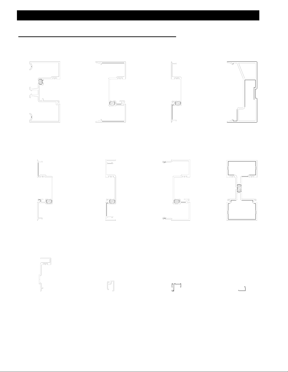
SECTION II: Parts Identification Chart
Vertical Parts:
16G1
Perimeter Jamb
16H6
Door Jamb Filler
with Deep Pocket
Mates With 16H3
16G8
Vertical Mullion
Mates With 16G9
16H9
Female Expansion
Mullion Shallow Pocket
Mates With 16J5
16G9
Vertical Mullion Filler
Mates With 16G8
16J5
Male Expansion
Mullion Deep Pocket
Mates With 16H9
16H3
Door Jamb
Mates With 16H6
16K6
Vertical Mullion
_Shear Block Only-
16H8
Vertical Applied Glass
Stop @ Door Transom
Mates With 4488
4488
Removable Transom
Glazing Stop
Mates With 16H8
4437
Applied Door Stop
Mates With 9155
9155
Applied Door Stop
Cover
Mates With 4437
EFCO 6/2012 Page 4
Page 5
Series 526 Impact Installation Instructions
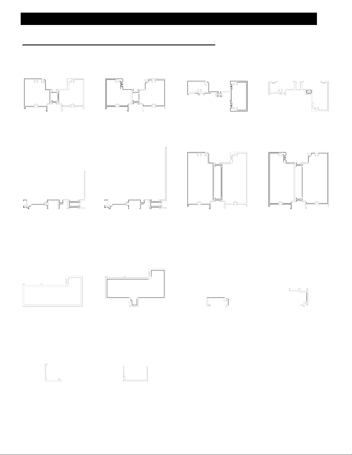
SECTION II: Parts Identification Chart
Horizontal Parts:
4G77
Outside Glaze Sill
Use With 4G79
4G79
Subsill
Use With 4G77, 4G78,
4G81 & 4G82
4G78
Inside Glaze Sill
Use With 4G79
4G80
4 1/2” Subsill
Use With 4G81 &
4G82
16H2
Horizontal
Use With 16G3 &
16G4
4G81
Outside Glaze
4 1/2” Sill
Use With 4G79 &
4G80
16G2
Head
Use With 16G3 &
16G4
4G82
Inside Glaze
4 1/2” Sill
Use With 4G79 &
4G80
16H4
Door Header
Use 16H7 Stop &
9914 Door Stop
16G4
Horizontal Fixed
Glass Stop Cover
Use With 16G3
@ 16H2 & 16G2
16H5
Door Header With
Fixed Glass Stop
Use 16H7 Stop
9914
Slide Arm Cover/
Door Stop
Use With 16H4
16H7
Door Header
Glass Stop
Use With 16H4 & 16H5
16G3
Horizontal Fixed
Glass Stop
Use With 16G4
@ 16H2 & 16G2
EFCO 6/2012 Page 5
Page 6

Series 526 Impact Installation Instructions
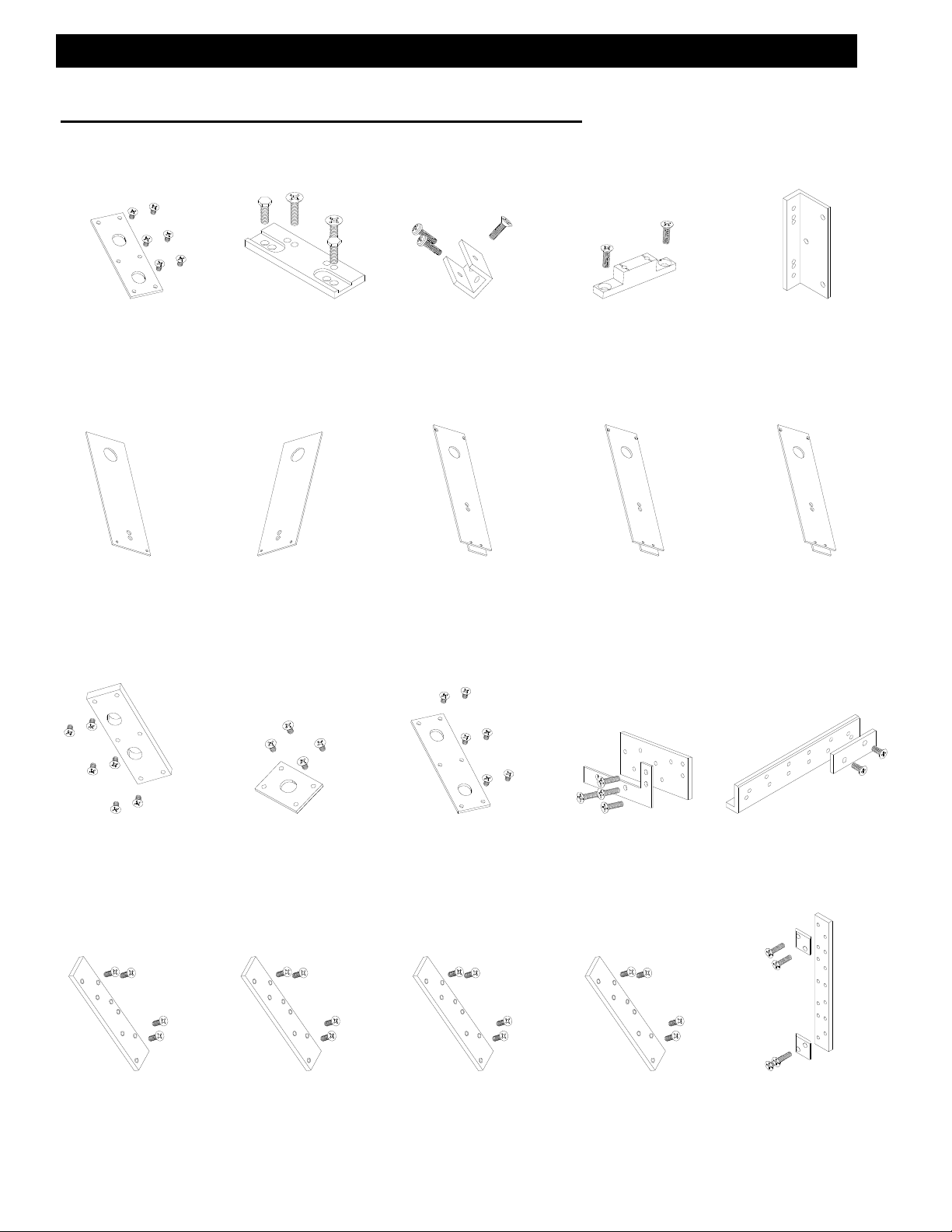
SECTION II: Parts Identification Chart
Shear Blocks:
KP01
Head & Horizontal
Shear Block Package
Use With 16H2 & 16G2
Setting Blocks:
K876
Door Header
Shear Block Package
Use With 16H4 & 16H5
KP04
Shear Block Package
With Shim for
Horizontal Thru
Use With 16K6
KP03
Shear Block Package
for Horizontal Thru
Use With 16K6
HEP0
Sill & Horizontal
Setting Blocks
Glazing Gasket:
W146
Dry Glazed
Preset Gasket
Weather Seal:
HN13
Door Header
Setting Block
W167
Drive-In Glazing
Gasket
WEQ1
Structural Glazed
Preset Gasket
EFCO 6/2012 Page 6
W138
Door Stop
Weather Seal
Page 7

Series 526 Impact Installation Instructions
SECTION II: Parts Identification Chart
Fasteners:
STC8
#12-14 X 1 1/4
PH-SMS 18-8 25
Drill Jigs:
SDR1
#10-16 X 3/4
PH-SMS SG TEK/2
STT6
#8-18 X 9/16
PH-SMS ZC TEK/2
S130
#8-15 X 1 3/4
PH-SMS 18-8 A
DJ28
Screw Spline Drill Jig
Miscellaneous:
FWB0
Water Deflector
Use @ 16H2
Shear Block Drill Jig
KP00
Subsill End Cap
Use @ 4G79
DJ29
KP10
4 1/2” Subsill End Cap
Use @ 4G80
HC03
Subsill Isolator
Use @ 4G77, 4G78,
4G81, & 4G82
WM01
Bond Breaker Tape
Use @ 4G79 & 4G80
HNA5
3/16” Anti-Walk Block
Use @16G9, 16K6, &
16H9 Shallow Pockets
EFCO 6/2012 Page 7
HNA7
5/8” Anti-Walk Block
Use @16H6
HNA6
3/4” Anti-Walk Block
Use @ 16G8, 16J5, &
16K6
HN53
13/16” Anti-Walk Block
Use @ 16G1 Jamb
FWE5
Foam Weep
Baffle
Use @ 4G79 & 4G80
Page 8
Series 526 Impact Installation Instructions
SECTION II: Parts Identification Chart
Miscellaneous:
KP11
3-Point Impact Lock
Strike Package
FT20
RH Cover Plate for
Dorma RTS-88 C.O.C.
at Offset Pivot
(Customer Specify Finish)
KP08
Dorma RTS-88 C.O.C.
Support PKG. for Butt
& Cont. Hinges
FT26
LH Cover Plate for
Dorma RTS-88 C.O.C.
at Offset Pivot
(Customer Specify Finish)
KP07
Dorma RTS-88 C.O.C.
F-Clip Spacer PKG. for
Butt & Cont. Hinges
K492
MILL Cover Plate for
Dorma RTS-88 C.O.C.
at Butt & Cont. Hinge
(Customer Specify Finish)
K435
Attachment Clip for
Dorma RTS-88 C.O.C.
F-Clip Spacer PKG. for
Offset Pivots
K495
Cover Plate for Dorma
RTS-88 C.O.C. at Butt
& Cont. Hinge
(Clear Anodize)
FT16
F-Clip for Dorma RTS-88
C.O.C. at Offset Pivots
Use Fasteners Supplied
With Closer
K496
Cover Plate for Dorma
RTS-88 C.O.C. at Butt &
Cont. Hinge
(Dark Bronze Anodize)
K936
Reinforcing PKG. for
Flush Bolt & 3-Point
Lock @ Head for Pair
Doors
K900
Butt Hinge Backer
PKG. for 4 1/2 X 4
Butt Hinges
(Clear)
K990
Reinforcing PKG. for
1490 Panic & 3-Point
Lock @ Threshold and
3-Point Lock @ Head
for Single Doors
K901
Butt Hinge Backer
PKG. for 4 1/2 X 4
Butt Hinges
(Bronze)
K987
Reinforcing PKG. for
1490 Panic @
Threshold for Pair
Doors
K904
Butt Hinge Backer
PKG. for 5 X 4 1/2
Butt Hinges
(Clear)
K999
Backer Plate & Shim
PKG. for 180/MP1
Top Pivots
K905
Butt Hinge Backer
PKG. for 5 X 4 1/2
Butt Hinges
(Bronze)
KP09
Baker Plate & Shim PKG.
for MP2/195 Bottom Pivot
K968
Door Jamb Mounting
Plate and Spacer PKG.
for M19/MP3
Intermediate Pivot
EFCO 6/2012 Page 8
Page 9
Series 526 Impact Installation Instructions
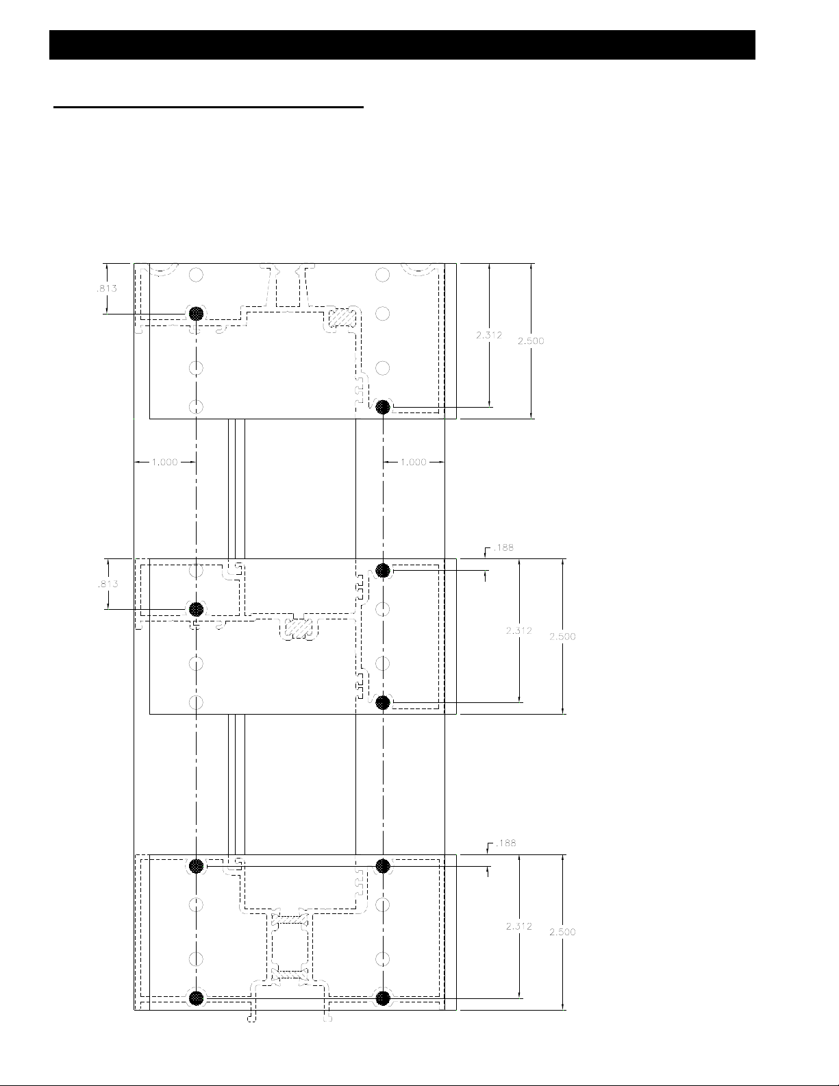
SECTION III: Fabrication
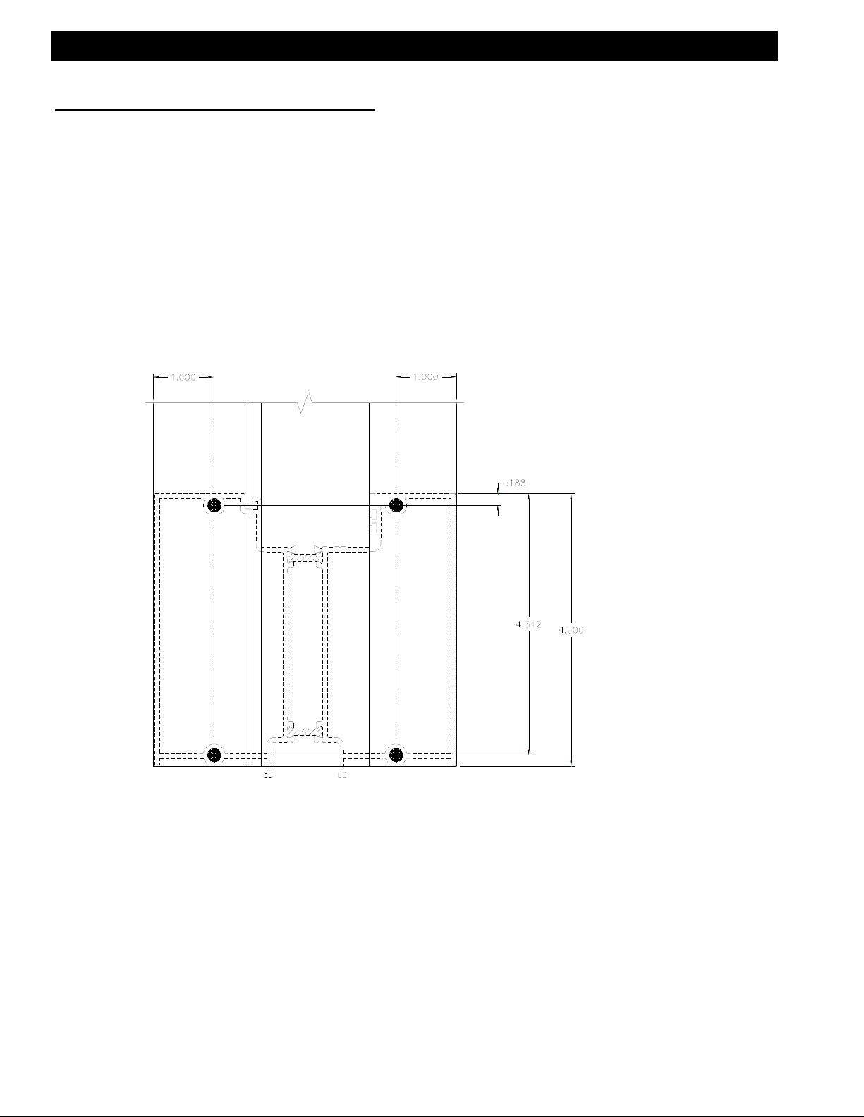
A. Drilling Template for Screw Spline at Verticals
Outside Glazed
Use the interior or exterior edge of the vertical to align drill jig,
DJ28. Drill with a .221 dia. (#2) drill at darkened areas only.
Dimension taken
from top of head.
526 SCREW SPLINE
Dimension taken
from top of horizontal.
526 SCREW SPLINE
526 SCREW SPLINE
Dimension taken
from top of sill.
EFCO 6/2012 Page 9
Page 10
Series 526 Impact Installation Instructions
SECTION III: Fabrication
B. Drilling Template for Screw Spline at Verticals
Outside Glazed (4 1/2” Sill)
Use dimensions as shown, or cut a short piece of the sill material and use as a template. Drill with a .221 dia. (#2) drill at
darkened areas only.
Dimension taken
from top of sill.
EFCO 6/2012 Page 10
Page 11

Series 526 Impact Installation Instructions
SECTION III: Fabrication
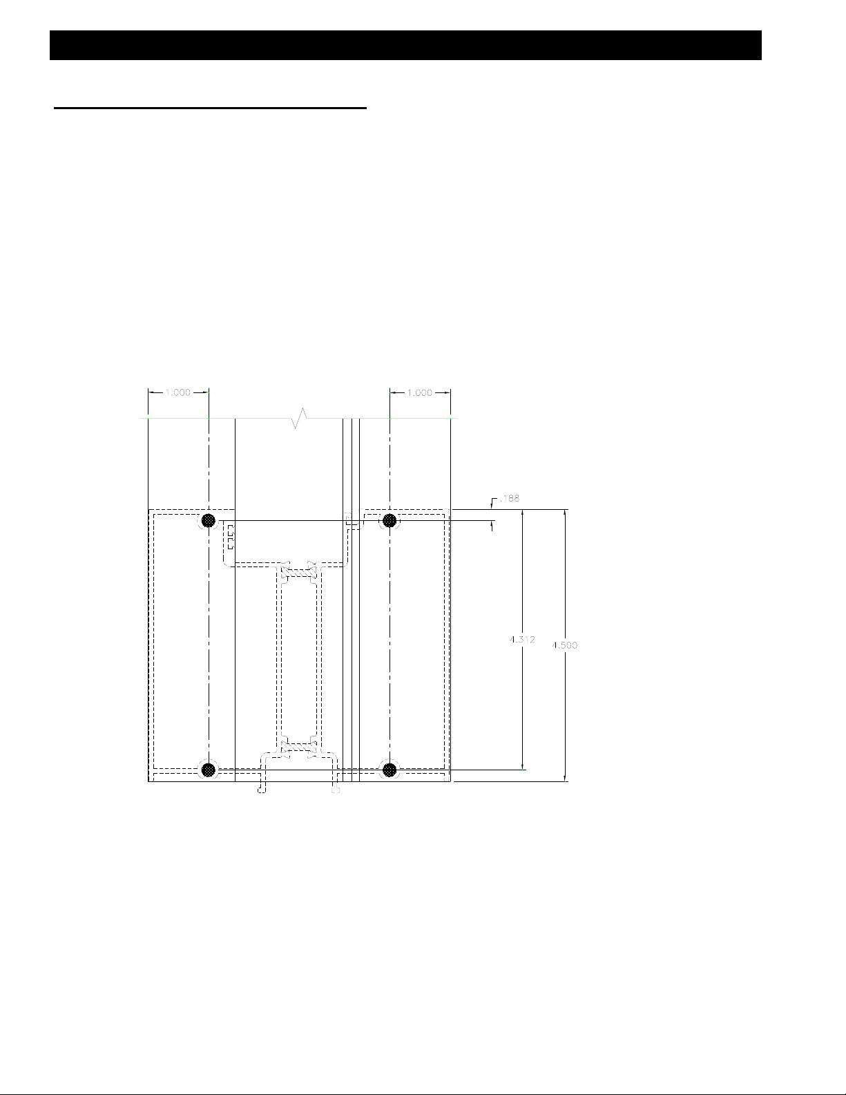
C. Drilling Template for Screw Spline at Verticals
Inside Glazed
Use the interior or exterior edge of the vertical to align drill jig,
DJ28. Drill with a .221 dia. (#2) drill at darkened areas only.
Dimension taken
from top of head.
526 SCREW SPLINE
Dimension taken
from top of horizontal.
526 SCREW SPLINE
526 SCREW SPLINE
Dimension taken
from top of sill.
EFCO 6/2012 Page 11
Page 12
Series 526 Impact Installation Instructions
SECTION III: Fabrication
D. Drilling Template for Screw Spline at Verticals
Inside Glazed (4 1/2” Sill)
Use dimensions as shown or cut a short piece of the sill
material to use as a template. Drill with a .221 dia. (#2) drill
at darkened areas only.
Dimension taken
from top of sill.
EFCO 6/2012 Page 12
Page 13
Series 526 Impact Installation Instructions
SECTION III: Fabrication
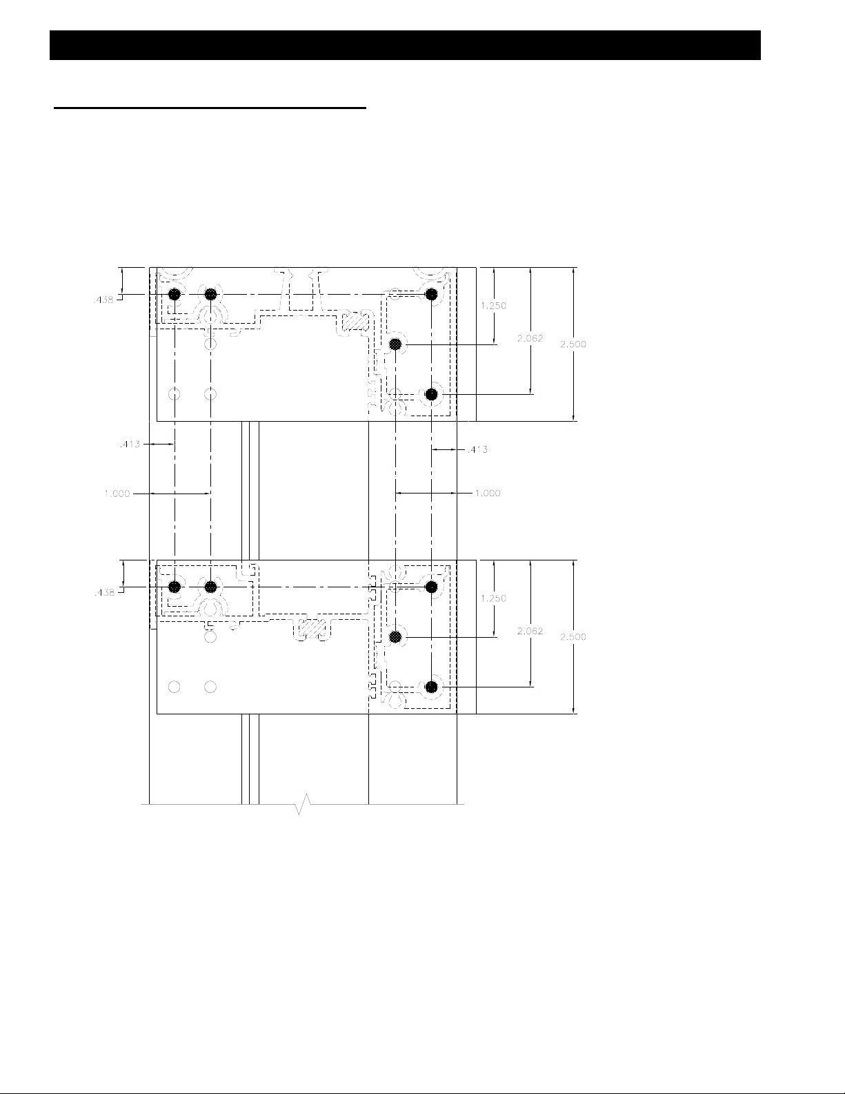
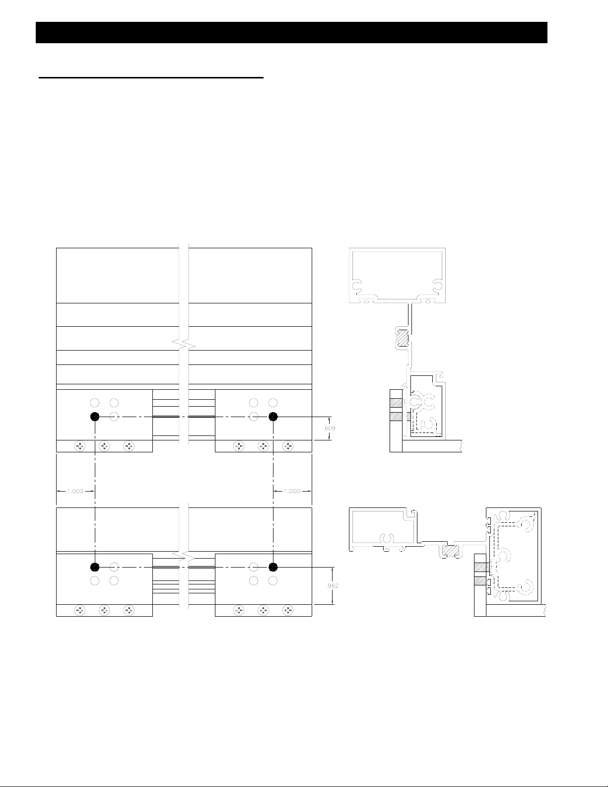
E. Drilling Template for Shear Blocks at Verticals
Outside Glazed
Use the interior or exterior edge of the vertical to align drill jig,
DJ29. Drill with a .182 dia. (#28) drill at darkened areas only.
Dimension taken
from top of head.
526 SHEAR BLOCK
Dimension taken
from top of horizontal.
526 SHEAR BLOCK
EFCO 6/2012 Page 13
Page 14
Series 526 Impact Installation Instructions
SECTION III: Fabrication
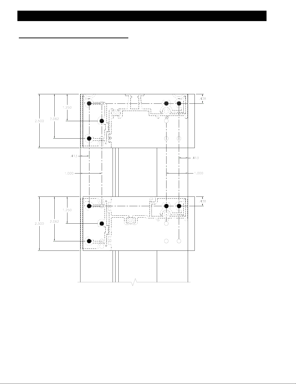
F. Drilling Template for Shear Blocks at Verticals
Inside Glazed
Use the interior or exterior edge of the vertical to align drill jig,
DJ29. Drill with a .182 dia. (#28) drill at darkened areas only.
Dimension taken
from top of head.
526 SHEAR BLOCK
Dimension taken
from top of horizontal.
526 SHEAR BLOCK
EFCO 6/2012 Page 14
Page 15
Series 526 Impact Installation Instructions
SECTION III: Fabrication
G. Drilling Template for Shear Blocks at Head and Horizontal
Inside Glazed and Outside Glazed
Align drill jig, DJ29, flush to the end of the head or horizontal.
Drill with a .221 dia. (#2) drill at darkened areas only.
EFCO 6/2012 Page 15
Page 16

Series 526 Impact Installation Instructions
SECTION III: Fabrication
H. Drilling Template for Shear Blocks at Horizontal
Use When Vertical Runs Between Horizontal
Use dimensions as shown when a vertical runs between horizontals. Drill with a .180 dia. (#15) drill at darkened
areas only.
This fabrication works with vertical attaching
to either the head, horizontal, or sill.
EFCO 6/2012 Page 16
Page 17

Series 526 Impact Installation Instructions
SECTION IV: Frame Assembly
A. Preset Gasket Installation for Dry Glazed and Wet Glazed
After all the material is cut to the appropriate length, the preset gasket should be
installed. Begin the installation of the preset gasket by first ensuring that the gasket
race is clean and free of debris. The preset gasket should be cut longer than the
frame member it is being installed into. Lay the preset gasket down the length the
frame member. Ensure that the gasket will hang over both ends of the frame
member because once the gasket is snapped-in place, it may be difficult to slide it in
the race. After the gasket is installed, crowd the gasket in from each end as much
as possible, and cut flush with the frame member.
Preset Gasket (W146)
for dry glazing
W146 gasket goes
into the outside track.
Snap the preset gasket into
the race by putting pressure
directly behind the dart.
Preset gasket (WEQ1)
for wet glazing
Snap the preset gasket into
the race by putting pressure
directly behind the dart.
WEQ1 gasket goes
into the inside track.
EFCO 6/2012 Page 17
Page 18

Series 526 Impact Installation Instructions
SECTION IV: Frame Assembly
B. Screw Spline Assembly
Inside Glazed and Outside Glazed
Each module must have at least one deep pocket vertical to facilitate glazing
installation. See page 39 for more detail on glazing pockets.
Apply sealant to both ends of all horizontals prior to assembling the module. After
module is assembled, clean off all excess butyl sealant.
Prior to applying sealant to the required areas, clean the area with Isopropyl Alcohol and a clean towel
that will not leave towel materials behind. Wipe off material with a sufficiently dampened towel to remove
all dust, oil, and cutting fluids from the required areas. Allow to air dry before applying any sealant.
Preset Gasket Typical
at All Frame Members
Deep Pocket
Butyl Sealant Typical
at All Horizontals
STC8 Assembly
Fasteners
Note:
Wax type lubricant may be
required @ assembly
fasteners.
Shallow
Pocket
EFCO 6/2012 Page 18
Page 19

Series 526 Impact Installation Instructions
SECTION IV: Frame Assembly
C. Door Frame Shear Block Assembly
Outside Glazed Only
Apply sealant to both ends of all the horizontals prior to assembling the module. After module is assembled, clean off all excess butyl sealant.
Shear block packages come with shear blocks and fasteners.
Prior to applying sealant to the required areas, clean the area with Isopropyl Alcohol and a clean towel
that will not leave towel materials behind. Wipe off material with a sufficiently dampened towel to remove
all dust, oil, and cutting fluids from the required areas. Allow to air dry before applying any sealant.
KP01 Head/Horizontal
Shear Block Package
Note:
Wax type lubricant may be
required @ assembly
fasteners.
Butyl Sealant Typical
at All Horizontals
Preset Gasket Typical
at All Frame Members
K876 Door Header
Shear Block Package
EFCO 6/2012 Page 19
Page 20

Series 526 Impact Installation Instructions
SECTION IV: Frame Assembly
D. Horizontal Thru Shear Block Assembly
Inside Glazed and Outside Glazed
Apply butyl type sealant to both ends of the vertical prior to assembling the module.
After module is assembled, clean off all excess butyl sealant.
Shear block packages come with shear blocks and fasteners.
Prior to applying sealant to the required areas, clean the area with Isopropyl Alcohol and a clean towel
that will not leave towel materials behind. Wipe off material with a sufficiently dampened towel to remove
all dust, oil, and cutting fluids from the required areas. Allow to air dry before applying any sealant.
KP04 vertical shear block
package used at bottom of
head or horizontal.
Butyl Sealant at Both
Ends of Vertical.
Note:
Wax type lubricant may be
required @ assembly
Fasteners.
KP03 vertical shear block
package used at top of
horizontal or sill.
EFCO 6/2012 Page 20
Page 21

Series 526 Impact Installation Instructions
SECTION V: Door Frame Installation
Step 1) General Notes
Door frames should be installed first, before all other framing material. The system
subsill must be installed from the door framing, ensuring that the appropriate clearance is
available for the door frame. All subsequent modules must be installed from the door
jambs outward.
The door frame module is shear block only. All sidelites will be screw spline application.
Door jambs do not set on the subsill. Door jambs must run through to the floor condition.
INSTALL 1ST
[Fig. 1]
Step 2) Subsill Installation at Door Opening
Where a door opening is required, use the equation in figure 1 above. Install the door
frame true and plumb in the opening as specified on the shop drawings or architectural
drawings. Install the subsill in the same manner as illustrated in figures 7-22 on pages 24
through 30. End dams are not required at the door frame end of the subsill. The subsill
should butt up tight to the door frame.
EFCO 6/2012 Page 21
Page 22

Series 526 Impact Installation Instructions
SECTION V: Door Frame Installation
Step 3) Subsill Sealant at Door Frame
Before installing the subsill to the door frame, seal the end of the subsill with a silicone
type sealant. Install the subsill, and tool all excess sealant into the joint where the subsill and door jamb meet. If required, add more sealant to create a smooth watertight seal.
Do not build-up excess sealant as it will keep the sill member of the frame pushed away
from the jamb, if allowed to cure before the sidelite frame is installed. At the glazing
pockets, a build-up of sealant must be used to fill the depth of the pocket up to the level
of the subsill at the glazing area. See figure 2 below for sealant application at the subsill
to door jamb joint.
Prior to applying sealant to the required areas, clean the area with Isopropyl Alcohol and a clean towel
that will not leave towel materials behind. Wipe off material with a sufficiently dampened towel to remove
all dust, oil, and cutting fluids from the required areas. Allow to air dry before applying any sealant.
[Fig. 2]
Tool sealant across all
seams to ensure a
watertight seal.
NOTE: Fill the glazing pocket of the door jamb flush with the sealant to the tallest portion
of the subsill that bridges the pocket. Tool the silicone so a watertight seal is made to
make sure that water will be directed out of the glazing pocket and into the subsill.
EFCO 6/2012 Page 22
Page 23

Series 526 Impact Installation Instructions
SECTION V: Door Frame Installation
Step 4) Door Header Identification
Depending on what type closer is used, two different door headers are available. The
header for surface closers has an extruded door stop and will not have a stop applied at
the door header. Concealed Overhead Closers (COC) do not have an extruded stop and
must have a slide arm cover/door stop applied. The 9914 stop is applied with S130 #8
FH fasteners in pre-located holes. Match drill the holes in the stop to the door header.
See figure 3 below for door header identification and stop application.
[Fig. 3]
Step 5) Door Jamb Stop Application
The door jambs are designed to accept a
screw applied door stop in a recessed area
of the door jamb. The applied door stops
should run from the top of the threshold to
the bottom of the door header stop. They
should be attached with STT6 TEK screws
@ 2" from each end and 9" on center
maximum. After the applied stop is attached,
snap-on the applied stop cover to hide the
attachment fasteners. See figure 4 for door
stop and cover application.
16H4 16H5
[Fig. 4]
9914
16H3
9155
4437
EFCO 6/2012 Page 23
Page 24

Series 526 Impact Installation Instructions
SECTION VI: Subsill Fabrication and Installation
Step 1) Subsill End Dam Requirements
Before installing the subsill into the rough opening, determine whether an end dam
(KP00) is required or not. If the surrounding condition does not have an open area or
can be used as a water dam, move to Step 3 on page 25. The first step to installation of
the end dams is to measure the rough opening width. The subsill length should be,
ROUGH OPENING WIDTH - 3/8". This formula will give enough room for the end dam
and attachment screws to fit on both ends of the subsill without interference with the
rough opening. (See figure 5 below.)
KP00 END DAM PACKAGE
[Fig. 5]
STC6
3/16 3/16
SUBSILL LENGTH = R.O. - 3/8
ROUGH OPENING
Step 2) Subsill End Dam Installation
Prior to installing the end dam, apply a generous amount of silicone type sealant to the
end of the subsill. Insert the STC6 fasteners into the end dam, and attach it to the end of
the subsill. After the end dam is attached, the excess sealant should be tooled at the
interior of the subsill/end dam joint to provide a watertight seal. Apply more sealant, if
required, for a watertight seal. (See figures 6 and 7.)
[Fig. 6]
Tool Sealant
STC6
[Fig. 7]
Butter the ends of the
subsill with silicone type
sealant prior to installation of the end dam.
Prior to applying sealant to the required areas, clean the area with Isopropyl Alcohol and a clean towel
that will not leave towel materials behind. Wipe off material with a sufficiently dampened towel to remove
all dust, oil, and cutting fluids from the required areas. Allow to air dry before applying any sealant.
EFCO 6/2012 Page 24
STC6
Page 25

Series 526 Impact Installation Instructions
SECTION VI: Subsill Fabrication and Installation
Step 3) Subsill Weep Fabrication
Drill 3/8” weep holes in subsill 6” from each jamb/vertical and no more than 42” apart.
[Fig. 8]
Step 4) Subsill Weep Baffle Installation
Weep baffles (FWE5) are placed on the subsill behind the weep holes. Apply a small
amount of silicone type sealant to the baffles, and locate them over the weep holes as
shown in figure 9. Ensure the sealant does not cover the weep holes.
[Fig. 9]
Apply sealant on bottom of
baffle before installation.
Step 5) Subsill Installation When End Dams Are Not Required
An end dam may not be required in all cases. Before installing a subsill without an end
dam, determine if the surrounding condition can be used to create a water dam, and if the
material will not degrade over time if it comes into contact with water. Once it has been
determined that the condition is appropriate to create a water dam, continue the installation of the subsill as described in Steps 6-10 of this section.
EFCO 6/2012 Page 25
Page 26

Series 526 Impact Installation Instructions
SECTION VI: Subsill Fabrication and Installation
Step 6) Benchmarks for Subsill Location
Before installing the subsill, the exterior face location of the frame should be found using
benchmark information from the shop drawings or architectural drawings. The subsill
protrudes 1/32" to the exterior of the exterior face of the frame. Locate this line based on
the benchmark information, and snap a chalk line to follow when installing the subsill.
The subsill exterior angled leg should follow the chalk line for correct installation.
Step 7) Preparing and Sealing the Subsill for Installation
Regardless of whether an end dam is used or not, the subsill must be sealed to the
condition to create a watertight condition when it is installed. It is also necessary to run a
continuous bead of silicone on the top of the strut. See figure 11 below. Begin the
process by cleaning the bottom and top strut of the subsill with a degreasing solution, and
wipe it dry after all foreign material has been removed. See figure 10 below. When the
subsill is clean and dry, run a bead of silicone type sealant across the top of the strut, and
tool smooth. Then turn the subsill over, and apply a generous amount of silicone type
sealant to the areas shown in figure 11. This should be done just prior to the
installation of the subsill.
Prior to applying sealant to the required areas, clean the area with Isopropyl Alcohol and a clean towel
that will not leave towel materials behind. Wipe off material with a sufficiently dampened towel to remove
all dust, oil, and cutting fluids from the required areas. Allow to air dry before applying any sealant.
[Fig. 10]
Silicone sealant
tooled smooth across
top of the strut.
[Fig. 11]
Clean and Degrease
Thoroughly
Silicone Sealant
EFCO 6/2012 Page 26
Page 27

Series 526 Impact Installation Instructions
SECTION VI: Subsill Fabrication and Installation
Step 7A) Shimming the Subsill if Required
In cases where the sill condition is not true and level, shimming may be required. The
subsill must be level and true and will need to be prepped as described in Step 7 on page
26. At the shimmed area, there is no need to apply sealant until after the subsill is set on
the condition and anchored as described in Step 8. See figures 14 and 15.
[Fig. 12]
[Fig. 13]
Clean and Degrease
Thoroughly.
Step 8) Anchorage of the Subsill
Silicone Sealant After
Anchorage When
Shims Are Required.
After the subsill has been cleaned and the silicone sealant has been applied, rotate the
subsill into position, and follow the chalk line location marks. Firmly press the subsill into
position so that the sealant is pressed uniformly onto the condition. Locate anchors on
the "V" groove of the subsill, tighten firmly and uniformly to anchor the subsill.
Anchors should be placed 6" from each end and 16" on center. Seal and tool the anchor
heads with silicone type sealant. See figure 14. These are general anchor location
guidelines. Size, space, and embedment of anchors as required to meet structural loads.
Shim as required.
Silicone Sealant
[Fig. 15]
EFCO 6/2012 Page 27
[Fig. 14]
Page 28

Series 526 Impact Installation Instructions
SECTION VI: Subsill Fabrication and Installation
Step 9) Sealing the Ends of the Subsill
After the subsill has been installed and anchored, it must be sealed to the condition at
each end with silicone type sealant. If the subsill has an end dam, there should be a
continuous bead of silicone type sealant placed up both the interior and exterior and
across the top edges of the end dam, where it meets the condition. The sealant should
be tooled to make a watertight seal between the end dam and the condition. If the subsill
does not have an end dam, a continuous bead of silicone type sealant must be applied
to the end of the subsill, where it meets the condition. The sealant should be tooled to
make a watertight seal between the subsill and the condition. See figures 16 and 17
below for sealant application.
Prior to applying sealant to the required areas, clean the area with Isopropyl Alcohol and a clean towel
that will not leave towel materials behind. Wipe off material with a sufficiently dampened towel to remove
all dust, oil, and cutting fluids from the required areas. Allow to air dry before applying any sealant.
[Fig. 16]
Tool sealant from
subsill end dam to
condition for a
watertight seal.
[Fig. 17]
Tool sealant from
subsill to condition
for a watertight
seal.
EFCO 6/2012 Page 28
Page 29

Series 526 Impact Installation Instructions
SECTION VI: Subsill Fabrication and Installation
Step 10) Splicing the Subsill
Verify that the subsills have been installed according to instructions on pages 24-28.
Splice areas should be centered at the vertical mullion only. Subsill length should never
exceed 20-25 feet. If a splice is required, leave a 1/4" gap between the subsill ends centered on a vertical mullion location. See figure 18. Use silicone type sealant and a strip of
WM01, bond breaker tape, 2" wide and approximately 7 1/2" long to create the splice material. Apply the sealant to both sides of the subsill ends, fill the void between the subsills
from the exterior to the interior at the condition, and fill the sill leg receptor cavities on both
subsills to a width of 2". See figure 19. Ensure that the bond breaker tape is centered
over the 1/4" gap, and set the bond breaker tape in the sealant. See figure 20. Tool the
sealant over the bond breaker tape to create a watertight seal. If more sealant is required
to cover the edges of the bond breaker tape, apply the required amount. Ensure that the
splice joint does not interfere with anchor legs of the sill or the leg receptors of the subsill.
This is done by making sure the splice joint is located at the center of a vertical mullion.
Refer to the shop drawings or architectural drawings for mullion center lines.
Prior to applying sealant to the required areas, clean the area with Isopropyl Alcohol and a clean towel
that will not leave towel materials behind. Wipe off material with a sufficiently dampened towel to remove
all dust, oil, and cutting fluids from the required areas. Allow to air dry before applying any sealant.
[Fig. 19]
[Fig. 18]
1/4
Sill Leg Cavity
Sealant
After splice tape is in
place, apply a cosmetic
seal along the 1/4” gap
at the interior of subsill.
2”
[Fig. 20]
WM01 Splice Tape
EFCO 6/2012 Page 29
Page 30

Series 526 Impact Installation Instructions
SECTION VII: Frame Installation
Step 1) Installing Sill Isolator
Before installing the jamb module into the opening, the sill isolator (HC03) must be in
place. Slide the isolator onto the interior interlock leg on the sill. See figure 21 below.
There will need to be one at each end of the sill at quarter points. Place a small amount of
sealant on the interlock leg at the quarter point location to hold the isolator in place while
installing the module.
[Fig. 21]
Step 2) Installing Jamb Module
Place the module on the subsill at an approximate 30° angle. While applying pressure
upward, rotate the module into the condition. See figure 22. When rotated correctly into
place, the interlocking legs of the sill will set inside the lock cavity of the subsill; the sill
should set flat on the subsill. See figure 23 for sill placement on the subsill.
Sill isolator placed at
1/4 points and held in
place with sealant.
[Fig. 23]
[Fig. 22]
EFCO 6/2012 Page 30
Page 31

Series 526 Impact Installation Instructions
SECTION VII: Frame Installation
Step 3) Anchoring the Jamb
Ensure that the frame jamb is true and plumb. Anchor through the jamb and into the
condition as shown in figures 24 and 25 below. As a general guideline, anchors will be
located 2” from head and sill with a maximum of 16” O.C. and 1/2” shimming.
Remember these are general anchor location guidelines. The size, space, and
embedment of anchors required to meet structural loads per job specifications will override
these guidelines.
[Fig. 24]
1/2” +/- Shim
as Required
[Fig. 25]
2”
16” MAX.
16” MAX.
16” MAX.
2”
EFCO 6/2012 Page 31
Page 32

Series 526 Impact Installation Instructions
SECTION VII: Frame Installation
Step 4) Anchoring the Head
For D.L.O.s 22" and narrower, the anchors must be spaced 2" from the jamb and vertical
members. Also, another anchor 4" from the intermediate vertical is required. For D.L.O.s
wider than 22", the outside anchors must be spaced in a similar manner, and all center
anchors must be located at 16" on center maximum. See figures 26 and 27 below for
anchor placement.
Remember these are general anchor location guidelines. The size, space, and
embedment of anchors required to meet structural loads per job specifications will
override these guidelines.
1/2” +/- Shim
as Required
[Fig. 27]
2”
16” MAX. 16” MAX.
2”
2”
[Fig. 26]
EFCO 6/2012 Page 32
Page 33

Series 526 Impact Installation Instructions
SECTION VII: Frame Installation
Step 5) Sealing Vertical Mullions
Prior to installing an intermediate vertical mullion or perimeter jamb, apply silicone type sealant to the vertical mullion in the location shown in figure 28 below. Both sides of the entire
mullion should be sealed. Apply enough sealant so when the filler or opposite
mullion half is snapped, it will create a good seal. Wipe off excess sealant from the exterior,
if required. This sealant practice should be used for screw spline vertical mullions only.
Prior to applying sealant to the required areas, clean the area with Isopropyl Alcohol and a clean towel
that will not leave towel materials behind. Wipe off material with a sufficiently dampened towel to remove
all dust, oil, and cutting fluids from the required areas. Allow to air dry before applying any sealant.
[Fig. 28]
Sealant at both
interior & exterior
Clean off any excess
sealant at both
interior and exterior.
[Fig. 29]
EFCO 6/2012 Page 33
Page 34

Series 526 Impact Installation Instructions
SECTION VII: Frame Installation
Step 6) Installing Subsequent Modules
Make sure that the anchors are installed into the head and jamb of the first module as
specified in figures 24-27 on pages 31 and 32. The silicone type sealant should be
applied to the mullion as specified in figure 28 on page 33. Place the second module on
the subsill at an approximate 30 degree angle. See figure 30 below. Rotate the module
into the condition approximately 1/4" away from the previously installed module. When
rotated correctly into place, the interlocking legs of the sill will set inside the lock cavity of
the subsill, and the sill should set flat on the subsill. See figure 23 on page 30 for sill
placement on the subsill. Once the second module is in place a 1/4" from the first
module, slide it into position and begin snapping the mullion halves together.
[Fig. 30]
Rotate module in place
about a 1/4” away from the
other vertical.
EFCO 6/2012 Page 34
Page 35

Series 526 Impact Installation Instructions
SECTION VII: Frame Installation
Step 7) Snapping Screw Spline Vertical Mullions Together
In some cases, it may be necessary to use a clamping device to get the mullions together
properly, if they cannot be snapped by hand. To do this, place one clamp at the bottom of
the mullions using wood blocks to protect the extrusions. Tighten the clamp until the
mullion halves begin to snap together. Place another set of wood blocks and a clamp at the
middle of the mullions and tighten it. Then repeat the same process at the top. Tighten the
clamps until the mullion halves are pressed together. The sight line should be 2 1/2". It
may be necessary to work from one clamp to the next several times, or move the clamps to
ensure the mullions are snapped together evenly. DO NOT try to hammer the mullion
halves together! This will dent, bend, scratch, or deform the mullions and may cause them
to leak. Ensure that the previous module is fully anchored before installing the next
module.
[Fig. 31]
Wood Block
or Similar
Use a C-Clamp
or Similar
Step 8) Anchoring Subsequent Modules
After the mullion halves are snapped correctly, ensure that the mullions are plumb and
true. Anchor the head as shown on page 32. If this is the last module in a run, ensure
that the mullion halves are snapped correctly, and install the required shims between the
jamb and condition. Install the head and jamb anchors as shown on pages 31 and 32.
Ensure that the jamb anchors do not separate the last module from the previous. It may
be necessary to shim tightly against the condition to prevent this. Seal and tool all anchor
heads with silicone type sealant.
EFCO 6/2012 Page 35
Page 36

Series 526 Impact Installation Instructions
SECTION VII: Frame Installation
Step 7) Perimeter Frame Sealant
All portions of the frame and surrounding conditions, where sealant will be applied, should
be cleaned and prepped per the sealant manufacturer's recommendations. Use silicone
type sealant to create the perimeter seal of the system at both exterior and interior
perimeters. Exterior and interior seals are required for air and water performance. Begin
by pushing caulk backer rod into position around the full perimeter of the frame at the head
and jambs. Push the backer rod into the gap, between the frame and condition, so it sets
below the frame edge. See figures 32 - 34 below for backer rod placement. The sealant
should be applied by a skilled tradesman to ensure proper seal and appearance. See
figures 33 and 35 below for sealant application. The sill and subsill will have a bead of
sealant across the full length of the subsill. See figure 35.
Prior to applying sealant to the required areas, clean the area with Isopropyl Alcohol and a clean towel
that will not leave towel materials behind. Wipe off material with a sufficiently dampened towel to remove
all dust, oil, and cutting fluids from the required areas. Allow to air dry before applying any sealant.
[Fig. 33]
Backer Rod
[Fig. 32]
[Fig. 35]
Sealant
[Fig. 34]
Backer Rod
Backer Rod
EFCO 6/2012 Page 36
Page 37

Series 526 Impact Installation Instructions
SECTION VIII: Glazing
Step 1) Setting Block Identification and Location
The setting block for standard frame horizontals is HEP0. The door headers require the use
of a HN13 setting block. Two setting blocks per D.L.O. are required and should be placed at
1/4 points or 1/8 points, depending on special dead load requirements. Depending on the
size and configuration of each DLO, the glass setting blocks must be placed to give the best
support of the glass without adding dead load weight to deflect the horizontal. Figure 36
below shows typical 1/4 point and 1/8 point setting block locations.
Contact EFCO Structural Engineering for blocking requirements, other than 1/4 and 1/8
points.
[Fig. 36]
DLO/8
DLO/4
DLO/4
DLO/8
DLO/4
DLO/4
Customer / Installer Note:
EFCO setting blocks are typically 4" in length with
different depths. If the glazing infill is "NOT BY
EFCO" and glazing sizes are larger than 40 square
feet, the glazing details must be reviewed by the
glazing manufacturer for proper setting block size.
EFCO 6/2012 Page 37
Page 38

Series 526 Impact Installation Instructions
SECTION VIII: Glazing
Step 2) Glazing Pocket Identification in Verticals
Ensure that each vertical DLO has at least one DEEP glass pocket on either side. It is
necessary for the glazing installation that a deep pocket be used to load the glazing units.
One exception is the applied transom glazing stops. The applied stops do not require the
glass to be loaded into a deep pocket. The details below (figure 37) are shown with the
deep glazing pockets to the right for viewing clarity.
16G9 16G8 16G1
16K6
Deep
Shallow
Deep
Shallow
Deep
[Fig. 37]
16H9 16J5 16H3 16H6
Transom
Deep
EFCO 6/2012 Page 38
Glazing Stops
Shallow
Deep
Page 39

Series 526 Impact Installation Instructions
SECTION VIII: Glazing
Step 3) Glass Size Formulas and Glass Bite (Verticals)
Glass size formulas are D.L.O. + 1 1/8" for both horizontal and vertical D.L.O.s. Glass bite
for all glazing is 9/16". See figure 38 below for horizontal glass size and bite and figure 39
on the next page for vertical glass size and bite.
EXPANSION
VERTICAL
JAMB
S.S. VERTICAL S.B. VERTICAL
DOOR JAMB
VERT. FILLER
9/16
[Fig. 38]
D.L.O.
D.L.O. + 1 1/8
5/16
9/16
9/16
9/16
DOOR JAMBS
D.L.O. + 1 1/8
D.L.O.
9/16
5/16
9/16
9/16
D.L.O. D.L.O.
D.L.O. + 1 1/8
9/16
9/16
D.L.O.
9/16
D.L.O. + 1 1/8
D.L.O. + 1 1/8
D.O.W
D.L.O. = D.O.W. – 5/8”
EFCO 6/2012 Page 39
Page 40

Series 526 Impact Installation Instructions
SECTION VIII: Glazing
Step 3A) Glass Size Formulas and Glass Bite (Horizontals)
HEAD
HORIZONTAL
SILL
D.L.O.
D.L.O.
[Fig. 39]
9/16
9/16
9/16
9/16
D.L.O. + 1 1/8
D.L.O. + 1 1/8
HEAD
DOOR HEADER
DOOR HEADER
D.L.O.
9/16
D.L.O. + 1 1/8
9/16
9/16
EFCO 6/2012 Page 40
Page 41

Series 526 Impact Installation Instructions
SECTION VIII: Glazing
Step 4) Installing the FWB0 Water Deflector
Install the FWB0 at the ends of the intermediate horizontals only. It is not required at
heads or sills. Use silicone type sealant to adhere the FWB0 on the intermediate
horizontal. Ensure that the thermal cavity is filled with sealant. Place FWB0 onto the top
of the intermediate horizontal glazing pocket, and smooth any excess sealant so water will
flow easily over the water deflector. See typical installation of the FWB0 in figures 40
through 42 below. The FWB0 will extend over the edge of the glass unit to deflect any
water from getting on the top of the unit below.
Prior to applying sealant to the required areas, clean the area with Isopropyl Alcohol and a clean towel
that will not leave towel materials behind. Wipe off material with a sufficiently dampened towel to remove
all dust, oil, and cutting fluids from the required areas. Allow to air dry before applying any sealant.
[Fig. 40]
[Fig. 41]
Sealant
Water Deflector
FWB0
[Fig. 42]
Edge of Glass
Tool sealant over
the top of the
FWB0.
EFCO 6/2012 Page 41
Page 42

Series 526 Impact Installation Instructions
SECTION VIII: Glazing
Step 5) Installing the Door Transom Glazing Adaptor
Before installing the transom glazing adaptor (16H8), it has to be fabricated. The cut
length is transom D.L.O. Transom D.L.O. is measured from top of door header to bottom
of transom head as shown in figure 39 on page 40.
To facilitate the installation of the door header glass stop, notch both ends of the adaptor
with a 1/2” X 7/16” notch as shown below.
Drill a .201 dia. (#7 Drill) clear hole 2” from each end and 9” on center maximum. Use the
“V” groove that is extruded into the adaptor as a guide for drill placement.
“V” Groove
[Fig. 43]
2”
D.L.O.
9” O.C.
Max.
9” O.C.
Max.
1/2”
2”
7/16”
EFCO 6/2012 Page 42
Page 43

Series 526 Impact Installation Instructions
SECTION VIII: Glazing
Step 5A) Installing the Door Transom Glazing Adaptor
The preset gasket will need to be pulled out of the corners or removed completely before
starting to install the 16H8 glazing adaptor. Run a bead of sealant from the bottom of the
head, down the interior edge of the glazing adaptor pocket, and across the pocket at the
top of the door header. Attach the glazing adaptor using SDR1 (10-16 X 3/4 TEK)
fasteners. Run a continuous bead of sealant across the seam of the glass legs and all the
way to the exterior edge of the glazing adaptor pocket in the jamb. Tool it to ensure a
watertight seal. Do this at both top and bottom of the adaptor. Snap the preset gasket
back into the gasket track before sealant sets up.
[Fig. 44]
Prior to applying sealant to the
required areas, clean the area
with Isopropyl Alcohol and a
clean towel that will not leave
towel materials behind. Wipe
off material with a sufficiently
dampened towel to remove all
dust, oil, and cutting fluids
from the required areas. Allow
to air dry before applying any
sealant.
Sealant
[Fig. 46]
SDR1
[Fig. 45]
Continuous Bead
of Sealant
EFCO 6/2012 Page 43
Page 44

Series 526 Impact Installation Instructions
SECTION VIII: Glazing
Step 6) Glass Installation
A. Make sure that the FWB0 is installed per the instructions on page 41.
B. Clean the ends of the horizontal preset gasket with alcohol. Clean the vertical, where
the horizontal butts up against it, with alcohol. Apply sealant to the end of the horizontal
so that it will create a seal when it butts against the vertical.
C. Insert the setting blocks at the predetermined 1/4 or 1/8 point locations.
D. Position the glass on the side of the frame that takes the removable glass stop.
E. Lift the glass over the sill, and shift the glass into the deep pocket to begin installation.
F. Rotate the glass into the glazing pocket, and slide the glass into the shallow pocket.
G. Adjust the glass so that an equal amount of glass bite is in each pocket.
[Fig. 47]
[Fig. 48]
Slide the glass into
the shallow pocket.
Lift the glass over the
sill, and shift the glass
into the deep pocket.
Customer / Installer Note:
EFCO setting blocks are typically 4" in length with
different depths. If the glazing infill is "NOT BY
EFCO" and glazing sizes are larger than 40 square
feet, the glazing details must be reviewed by the
glazing manufacturer for proper setting block size.
EFCO 6/2012 Page 44
Page 45

Series 526 Impact Installation Instructions
SECTION VIII: Glazing
Step 7) Attaching Glass Stop and Glass Stop Cover
The 16G3 glass stop has a hook leg that has to go past the frame hook leg towards the
glass. So,it is necessary to push the glass against the preset gasket. This will give the
16G3 leg enough clearance of the frame hook leg. Lift and pull into place. It may be
necessary to use short pieces of the drive-in gasket (W167) to temporarily hold it in place.
For DRY glazing, it is necessary to use SDR1 (10-16 X 3/4 TEK) fasteners to attach the
glass stop, but for a WET glazing, the SDR1 is optional. Predrill the 16G3 glass to locate
the SDR1 6” from each end, and one in the center for anything over 36” a maximum of 24”
on center. Place the short temporary pieces of W167 at fastener locations. This will keep
the 16G3 in place while attaching.
[Fig. 49]
Glass stop must go
below frame hook
leg and against the
glass to be able to
snap into place.
Frame Hook Leg
Glass Against
Preset Gasket
EFCO 6/2012 Page 45
Page 46

Series 526 Impact Installation Instructions
SECTION VIII: Glazing
Step 8) Anti-Walk Block Installation
Stretch the anti-walk block out as flat as possible, and insert it in between the glass and
frame so that it opens up inside the glass pocket at midspan of the D.L.O. at the deep
pocket. See figure 50 below. This can only be done from the drive-in gasket side of the
frame. After the deep pocket anti-walk block is installed, slide the glass unit over against
the anti-walk block, and insert one into the shallow pocket at midspan of the D.L.O. If
Necessary, re-center the glass unit to maintain equal glass bite all around.
[Fig. 50]
Anti-Walk Block
HN53
HNA5
shallow pocket
HNA6 - use @ 16G8, 16J5 & 16K6
deep pocket
HNA7
- use @ 16G1
- use @ 16G9, 16K6 & 16H9
- use @ 16H6
EFCO 6/2012 Page 46
Page 47

Series 526 Impact Installation Instructions
SECTION VIII: Glazing
Step 9) Drive-in Glazing Gasket Installation
Ensure that the glass, setting blocks, snap-in glazing bead, and anti-walk blocks have
been installed according to the instructions on the previous pages. Begin by measuring
the D.L.O. width and height. Cut the drive-in glazing gasket (W167) to length by using the
following formula.
EXTERIOR GASKET CUT LENGTH = D.L.O. DIM + 2% (D.L.O. DIM X 1.02)
Seal 1” vertically and horizontally in the gasket race with silicone type sealant at all
corners. Seal the ends of the horizontal gaskets to the vertical gaskets. To install the
W167 gasket, start by pushing the precut gasket in place at the ends. Move to the middle,
then to 1/4 points, and work the "waves" toward the ends. Try to maintain 8" to 12" placement of the gasket to ease the installation.
Note: Install the vertical gasket first, then run the horizontal gasket into it.
[Fig. 51]
[Fig. 52]
Sealant 1” up the
vertical and 1”
across horizontal.
EFCO 6/2012 Page 47
Page 48

Series 526 Impact Installation Instructions
SECTION VIII: Glazing
Step 10) Inside Glazed Glass Stop Seal (Dry Glazed Only)
After installing the 16G3 glass stop, run a bead of silicone type sealant across the seam
of the glass stop and jamb, then fill the gasket raceway with sealant. Tool the sealant to
make a watertight seal. See figure 53 below.
[Fig. 53]
EFCO 1/2013 Page 48
Sealant to
follow the
profile of the
glass stop.
Page 49

Series 526 Impact Installation Instructions
SECTION VIII: Glazing
Step 11) Appling the Glass Stop Cover
The glass stop cover (16G4) is snapped in place after the drive-in gasket is glazed. It may
be necessary to use a soft face mallet to snap the cover into place. Start by pressing the
cover down so that it will clear the frame snap leg, then run it to the other end.
Press the cover
snap leg past the
frame snap leg.
[Fig. 54]
Hit with a soft
face mallet at
this corner.
EFCO 6/2012 Page 49
Page 50

Series 526 Impact Installation Instructions
SECTION VIII: Glazing
Step 12) Wet Glazed Application (Outside Glazed Only)
When glazing a wet glazed unit, follow all the previous instructions in this manual and
substitute the W146 gasket with WEQ1.
Begin the interior glass sealant application by ensuring that the glass and metal are
cleaned and dry per the sealant manufacturer's instructions. Apply sufficient structural
silicone sealant to the gap between the glass and metal to fill the void back to the interior
gasket on all sides of each DLO. Ensure that air pockets in the sealant are not present as
this would create a weak area in the glass and metal adhesion. Tool the sealant flat
against the metal for a clean cosmetic appearance. It may be beneficial to use a form of
masking tape on the metal and/or glass to aid in the clean appearance of the seal and to
lessen the clean-up effort. See figure 55 below for sealant application.
[Fig. 55]
Structural Silicone
Sealant
WEQ1 Gasket
Structural Silicone
Sealant
EFCO 6/2012 Page 50
 Loading...