

Page 1

Series 525 impact storefront
Installation Instructions
Part NO. Y020
February 2013
Page 2

TABLE OF CONTENTS
SECTION PAGE
I GENERAL NOTES
II PARTS IDENTIFICATION
III FABRICATION
A. DRILLING TEMPLATE
(SCREW SPLINE VERTICALS)
B. DRILLING TEMPLATE
(SHEAR BLOCK VERTICALS)
C. DRILLING TEMPLATE
(SHEAR BLOCK AT HORIZONTALS.)
D. SILL WEEP NOTCHES
IV INTERIOR GASKET INSTALLATION
V UNIT ASSEMBLY
A. SCREW SPLINE
B. SHEAR BLOCK
1
2 - 6
7
8
9 -10
11
12
13
14
VI DOOR FRAME INSTALLATION
VII SUBSILL FABRICATION AND INSTALLATION
VIII FRAME INSTALLATION
A. SCREW SPLINE
B. SHEAR BLOCK
C. PERIMETER SEALANT
IX GLAZING
Mini mizing Condensation
NOTE: Please reference EFCO's "Understanding Condensation" brochure which can be obtained through your EFCO representative.
Condensation will form on any surface when unfavorable conditions (interior temperature and relative humidity and exterior
temperature) are present. When the formation of excessive condensation is a concern, it is highly recommended that a design
professional is utilized to perform an analysis of the shop drawings to recommend the best installation methods. Please contact
EFCO representative for information on EFCO's Thermal Analysis Services.
Many current installation practices lead to an increase in the possibility of the formation of condensation. Though not all
inclusive, the list of examples below illustrates conditions under which condensation is likely to occur:
1. Bridging system thermal break with non-thermally broken metal flashing or lintels that are exposed to the
exterior.
2. System exposure to cold air cavities.
3. Interior relative humidity levels not maintained at recommended levels, see EFCO's "Understanding
Condensation" brochure.
4. Inadequate separation between system and surrounding condition at perimeter.
5. Product combinations during the shop drawing stage that result in bridging thermal breaks of one or all products
involved.
15 - 19
20 - 24
25 - 31
32 - 33
34
35 - 42
Page 3

PAGE 1
SECTION I - GENERAL NOTES
The "Series 525" is a framing system that is designed for impact
resistance of windborne debris. It can be used as a single-span
storefront window wall, a punched opening system, or as a ribbon
window system. The system can be fabricated for both screw
spline and shear block construction.
The Series 525 system contains primarily stock length material
with in-the-field fabrication, or it may be fabricated in the shop for
delivery to the job site. Entrance doors are also an integrated
part of this system, utilizing frame members and hardware
support systems that accommodate doors and door hardware
that will withstand impact from windborne debris.
1.) Check the shop drawings, installation instructions, and glazing instructions to
become thoroughly familiar with the project. The shop drawings take precedence and
include specific details for the project. The installation instructions are of a general
nature and cover the most common conditions encountered.
2.) Check all materials on arrival and be sure you have everything required to begin
installation. See Section II "PARTS IDENTIFICATION" for parts cross reference.
3.) All work should start from bench marks and/or column center lines as established
by the architectural drawings and the general contractor. Installers should check
building construction for compliance with architectural documents to ensure the proper
window system foundation is available before installation.
4.) The term "sealant" as used in these instructions is defined as: A weather resistant,
gunable liquid filler, when dry, provides a resilient, flexible air and water seal between
similar and dissimilar materials. In these instructions Dow Corning 795 or equivalent is
used when silicone sealant is required and PTI 707 or equivalent is used when butyl
type sealant is required. Dow Corning 995 or equivalent structural silicone is used
where glazing sealant is required.
All sealant must be compatible with all surfaces on which adhesion is required,
including other sealant surfaces. All frame surfaces should be clean and dry. All
perimeter substrate shall be cleaned and properly treated to receive sealant.
5.) All materials are to be installed plumb, level, and true.
6.) Protect materials after erection. Cement, plaster, alkaline solutions, and acid based
materials can be harmful to the finish. Clean exposed finished surfaces with a mild
detergent and water. No abrasive cleaning agent should be used.
525 IMPACT
DPS 1/2004
Page 4

SECTION II - PARTS IDENTIFICA TION CHART
PAGE 2
VERTICALS
DESCRIPTION
PERIMETER JAMB
-SHEAR BLOCK OR
SCREW SPLIN E-
VERTICAL MULLION
-SHEAR BLOCK ONLY-
VERTICAL MULLION
(Deep Pocket )
-SCREW SPLINE ONLYUse with 4481
VERTICAL MULLION FILLER
(Shallow Pocket)
-SCREW SPLINE ONLY-
Use with 4480
MALE EXPANSION
MULLION
PART NO.
4476
4477
4480
4481
16D2
DOOR FRAMES
DESCRIPTION
DOOR JAMB
-SHEAR BLOCK ONLYUses 4437/9155 door stop and
4487/4488 transom glass stop.
STD. DOOR HEADER
-SHEAR BLOCK ONLY-
Uses 4486 glazing bead.
C.O.C. DOOR HEADER
-SHEAR BLOCK ONLY-
Use with 4486 glazing bead.
DOOR HEADER
GLAZING BEAD
Use with 4483 and
4484 door headers.
FIXED TRANSOM
GLASS STOP
Use with 4488 glass stop at
4478 door jamb.
PART NO.
4478
4484
4483
4486
4487
FEMALE EXPANSION
MULLION
HORIZONTALS
HEAD
INTERMEDIATE
HORIZONTAL
SILL
Interlocks with 4482
subsill only.
Use with 4485 stop
GLAZING BEAD
Use with 4475 and 4491.
16D1
4479
4491
4475
4485
REMOVABLE TRANSOM
GLASS STOP
Use with 4487 glass stop at 4478
door jamb.
DOOR STOP
Use with 9155 door stop cover at
4478 door jamb.
DOOR STOP
Use with 9155 door stop cover at
2" doors and 4478 door jamb.
DOOR STOP COVER
Use with 4437 door stop at 4478
door jamb.
SLIDE ARM COVER/DOOR
STOP
Use with 4483 C.O.C. door header
4488
4437
4399
9155
9914
SUBSILL
Interlocks with 4475 sill only.
4482
SHAPES ON THIS PAGE ARE NOT TO SC ALE
MDM 04/06
Page 5

PAGE 3
5
SECTION II - PARTS IDENTIFICATION CHART
SHEAR BLOCKS
DESCRIPTION PART NO.
HORIZ. & SILL SHEAR
BLOCK PACKAGE
Use wit h 4 475 & 4491
(1) FU22, (1) FU21, (5) STB5, (2) STS0
FRAME HEAD SHEAR
(2) FU21, (2) S101, (2) S103, (4) STB5
DOOR HEADER SHEAR
Use wit h 4 484 & 4483
LH or RH
BLOCK PACKAGE
LH or RH
Use with 4479
BLOCK PKG.
LH or RH
(1) FV67, (2) STV2, (2) STD8
K998
K997
K876
GLAZING GASKETS
DESCRIPTION
EXTERIOR GLAZING
GASKET
Used with 9/16" and
5/8" glazing.
EXTERIOR GLAZING
GASKET
Used with 7/16" and 1/2"
glazing.
EXTERIOR GLAZING
GASKET
Used with 11/16"
glazing.
INTERIOR GLAZING
GASKET
Used w ith all glazing.
PART NO.
W164
W165
W166
WEQ1
(CONT.)
SETTING BLOCK S
GLASS SETTING BLOCK
Used wi th 4491
horizontal
and 4475 sill.
GLASS SETTING BLOCK
Used with 4483 and 4484
door headers.
WEATHER SEALS
HN43
HN91
DRILL FIXTURES
SCREW SPLINE
DRILL JIG
USED AT VERTICALS
SHEAR BLOCK
DRILL JIG
USED @ V ERTICALS AND
HORIZONTALS
DJ20
DJ19
525 IMPACT
SHAPES ON THIS PAGE ARE NOT TO SCALE
BAH 9/200
Page 6

PAGE 4
SECTION II - PARTS IDENTIFICA TION CHART
FASTENERS
DESCRIPTION
PART NO. DESCRIPTION
STC8
STB5
STV2
STS0
PART NO.
MRB8
S118
M130
M131
(CONT.
S101
S103
STT6
M148
STC7
M160
M161
SHAPES ON THIS PAGE ARE NOT TO SC ALE
Page 7

SECTION II - PARTS IDENTIFICATION CHART
PAGE 5
(CONT.)
MISC. PARTS
DESCRIPTION
WATER DEFLECTOR
@ INT. HORIZONTAL
BOND BREAKER TAPE
4" X .062"
USED @ SUBSILL SPLICES
DORMA RTS-88 C.O.C.
SUPPORT PKG. FOR BUTT
& CONTINUOUS HINGES
RHRB
DORMA RTS-88 C.O.C.
SUPPORT PKG. FOR BUTT
& CONTINUOUS HINGES
LHRB
DORMA RTS-88 C.O.C.
F-CLIP SPACER PKG. FOR
BUTT & CONT. HINGES
ATTACHMENT CLIP FOR
DORMA RTS 88 C.O.C. FOR
OFFSET PIVOTS
F-CLIP FOR DORMA RTS 88
C.O.C. AT OFFSET PIVOTS
USE FASTENERS SUPPLIED
WITH CLOSER.
RH COVER PLATE FOR
DORMA RTS 88 C.O.C. AT
OFFSET PIVOTS
(CUSTOMER SPECIFY FINISH)
PART NO.
HWD1
WM01
K874
K873
K875
K435
FT16
FT20
MISC. PARTS
DESCRIPTION
MILL COVER PLATE FOR
DORMA RTS 88 C.O.C. AT
BUTTS AND CONT. HINGE
(CUSTOMER SPECIFY FINISH)
COVER PLATE FOR
DORMA RTS 88 C.O.C. AT
BUTTS AND CONT. HINGE
(CLEAR ANODIZE)
COVER PLATE FOR
DORMA RTS 88 C.O.C. AT
BUTTS AND CONT. HINGE
(DRK. BRNZ. ANODIZE)
REINFORCING PKG. FOR
FLUSH BOLT & 3-POINT
@ HEAD
LOCK
FOR PAIR DOORS
REINFORCING PKG.
FOR 1490 PANIC & 3-POINT
LOCK @ THRESHOLD AND
@ HEAD FOR SINGLE DOOR
3-POINT LOCK
REINFORCING PKG.
FOR 1490 PANIC
@ THRESHOLD
FOR PAIR DOORS
PART NO.
K492
K495
K496
K936
K990
K987
525 IMPACT
LH COVER PLATE FOR
DORMA RTS 88 C.O.C. AT
OFFSET PIVOTS
(CUSTOMER SPECIFY FINISH)
FT26
SUBSILL END DAM
PACKAGE
USED WITH 4482 SUBSILL
SHAPES ON THIS PAGE ARE NOT TO SCALE
KN66
DPS 3/2004
Page 8

PAGE 6
SECTION II - PARTS IDENTIFICATION CHART
MISC. PARTS
DESCRIPTION
BACKER PLATE & SHIM
PACKAGE FOR 180/MP1
TOP PIVOTS
LEFT HAND MP2/195
BOTTOM PIVOT BACKER
PACKAGE
RIGHT HAND MP2/195
BOTTOM PIVOT BACKER
PACKAGE
PART NO.
K999
KN04
KN05
MISC. PARTS
PART NO.DESCRIPTION
(CONT.)
DOOR JAMB MOUNTING
PLATE & SPACER PKG.
FOR M19/MP3 INT. PIVOT
BUTT HINGE BACKER PKG.
FOR 4 1/2 X 4 BUTT HINGES
(CLEAR)
BUTT HINGE BACKER PKG.
FOR 4 1/2 X 4 BUTT HINGES
(BRONZE)
BUTT HINGE BACKER PKG.
FOR 5 X 4 1/2 BUTT HINGES
(CLEAR)
BUTT HINGE BACKER PKG.
FOR 5 X 4 1/2 BUTT HINGES
(BRONZE)
K968
K900
K901
K904
K905
525 IMPACT
SHAPES ON THIS PAGE ARE NOT TO SCALE
DPS 1/2004
Page 9

PAGE 7
SECTION III-FABRICATION A - DRILLING TEMPLATE
SCREW SPLINE VERTICALS
USE THE INTERIOR EDGE OF THE VERTICAL TO
ALIGN DRILL JIG DJ20. USE .221 DIA. (#2) DRILL
AT DARKENED AREAS ONLY.
PERIMETER JAMB SHOWN, VERTICAL MULLION AND FILLER SIMILAR.
EXTERIOR
.188"
1.687"
1.000"1.000"
1.000"1.000"
2.312"
REF.
.188"
2.312"
INTERIOR
.188"
2.500"
2.500"
(HEAD)
(HORIZONTAL)
525 IMPACT
1.687"
1.000"1.000"
[FIG. 1]
1.000"
1.000"
.188"
2.500"
(SILL)
DPS 1/2004
Page 10

PAGE 8
SECTION III-FABRICATION B - DRILLING TEMPLATE
SHEAR BLOCK VERTICALS
USE THE INTERIOR EDGE OF THE VERTICAL TO
ALIGN DRILL JIG DJ19. USE .182 DIA. (#28) DRILL
AT DARKENED AREAS ONLY.
PERIMETER JAMB SHOWN, VERTICAL MULLION SIMILAR.
EXTERIOR
2.062"
.563"
.329"
.329"
1.812"
.313"
1.000"
1.000"
1.000"
1.375"
.329"
.625"
.375"
1.437"
INTERIOR
2.500"
.563"
.313"
2.125"
(HEAD)
(HORIZONTAL)
2.500"
525 IMPACT
2.062"
.329"
1.812"
1.000"
[FIG. 2]
1.375"
.625"
.375"
1.437"
2.125"
2.500"
(SILL)
DPS 1/2004
Page 11

PAGE 9
SECTION III-FABRICATION C - DRILLING TEMPLATE
SHEAR BLOCK HORIZONTALS
USE THE INTERIOR & EXTERIOR EDGE AND EACH END OF THE
HEAD TO ALIGN DRILL JIG DJ19. USE .228 DIA. (#I) DRILL AT
DARKENED AREAS ONLY FOR STEP 1.
AFTER STEP 1 IS COMPLETE, PROCEED TO STEP 2.
COUNTERSINK HOLES 82˚ TO .438 DIAMETER.
.625"
.625"
(STEP 1)
1.000"
1.000"
1.000"
1.000"
PREP FOR FRAME HEAD.
.625"
.625"
INTERIOR
EXTERIOR
4479 HEAD
[FIG. 3]
.625"
525 IMPACT
.625"
1.000"
1.000"
82˚ CTSK
@ .438 DIA.
(2) EACH END
1.000"
1.000"
.625"
.625"
INTERIOR
4479 HEAD
[FIG. 4]
EXTERIOR
DPS 1/2004
Page 12

PAGE 10
SECTION III-FABRICATION C - DRILLING TEMPLATE
(CONT.)
SHEAR BLOCK HORIZONTALS
USE THE EXTERIOR EDGE AND EACH END OF THE HORIZONTAL OR
SILL TO ALIGN DRILL JIG DJ19. USE .228 DIA. (#I) DRILL AT DARKENED
AREAS ONLY FOR STEP 1.
AFTER STEP 1 IS COMPLETE, PROCEED TO STEP 2. ROTATE THE
MATERIAL, AND USE THE EDGE OF THE GLAZING POCKET AND THE
END OF EACH HORIZ. OR SILL TO ALIGN DRILL JIG DJ19. USE A .228
DIA. (#I) DRILL AT DARKENED AREAS ONLY FOR STEP 2.
PREP FOR FRAME
HORIZ. AND SILL
(STEP 1)
.625"
1.054"
1.000"
[FIG. 5]
(STEP 2)
1.000"
1.000"
1.000"
1.054"
.625"
4491
HORIZ.
EXTERIOR
1.054"
4475
SILL
EXTERIOR
[FIG. 6]
525 IMPACT
4491 HORIZ. SHOWN
4475 SILL SIM.
DPS 1/2004
Page 13
PAGE 11
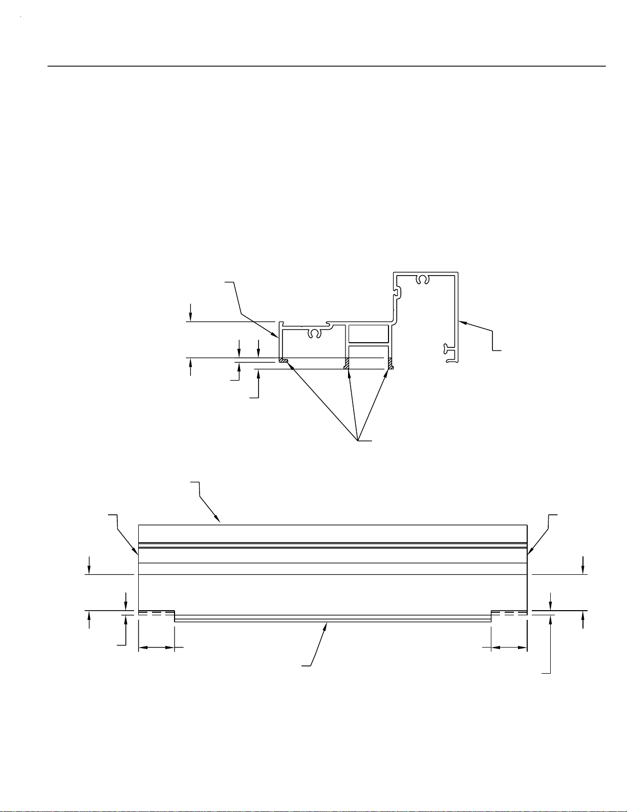
SECTION III-FABRICATION D - SILL WEEP NOTCHES
To evacuate water from the system, weep notches must be placed at
the ends of each sill. This notch will manifest itself as a 1/8" X 1" notch
at each end of the sill, joining the vertical at the exterior face of the sill.
The notch also must remove the two extended legs in the middle
portion of the sill. These legs must be removed at the same height as
the face notch and requires that more material be removed. This
material removal will not be seen because it is under the sill and is
covered by the subsill. Refer to figures 7 and 8 below for notching
layout.
END OF
SILL
EXTERIOR
1" REF.
TOP OF
SILL
1/8"
5/16"
4475
SILL
INTERIOR
[FIG. 7]
NOTCH LEGS
AT EACH END
END OF
SILL
1" REF.
ENSURE THAT THE EXTERIOR NOTCH IS CLEAN
AND UNIFORM FOR GOOD WATER FLOW, AND TO
MAKE THE NOTCH AS UNOBTRUSIVE AS
POSSIBLE WHEN VIEWED FROM THE EXTERIOR.
525 IMPACT
1/8"
1"
BOTTOM
OF SILL
1" REF.
1"
[FIG. 8]
1/8"
DPS 1/2004
Page 14

PAGE 12
SECTION IV - INTERIOR GASKET INSTALLATION
STEP 1) INTERIOR GASKET INSTALLATION
After all material is cut to the appropriate length, the WEQ1 interior
gasket/sealant backer should be installed. Begin the installation of the WEQ1
by first ensuring that the gasket race is clean and free of debris. The WEQ1
should be cut to the same length as the frame member it is being installed into.
Begin the installation on one end of the frame member and slide the WEQ1
into the raceway. It may be advantageous to use a light mixture of soapy
water to help the gasket slide into the race. After installation, ensure that the
WEQ1 is not stretched an excessive amount.
It is "possible" to install the WEQ1 after the frame members are assembled,
but it has to be pressed into the gasket race instead of sliding in. This is "far
more difficult and time consuming" and should be avoided unless absolutely
necessary. If the WEQ1 must be installed after the frame material is
assembled, a tool with a hooked tip of some type will ease the installation of
the gasket, as will a light mixture of soapy water. Refer to figure 9 below for
WEQ1 installation.
4477 SHOWN
OTHERS SIMILAR
EXTERIOR FACE
WEQ1
INTERIOR
GASKET
WEQ1
(INSTALLED)
SLIDE WEQ1 INTO
GASKET RACE
[FIG. 9]
525 IMPACT
DPS 1/2004
Page 15

PAGE 13
SECTION V-UNIT ASSEMBLY A - SCREW SPLINE
[FIG. 10]
DEEP
POCKET
4480
4479
BUTTER THE ENDS OF
ALL HORIZONTALS WITH
PTI 707 OR EQUIVALENT
BUTYL TYPE SEALANT
AS SHOWN BY THE
SHADED AREAS PRIOR
TO ASSEMBLY OF THE
UNITS.
STC8
STC8
DEEP
POCKET
4481
4491
STC8
4475
STC8
EXTERIOR FACE
ENSURE THAT EACH MODULE HAS A DEEP GLAZING
POCKET ON ONE SIDE AND A SHALLOW GLAZING
POCKET ON THE OTHER TO FACILITATE GLAZING
INSTALLATION.
525 IMPACT
STC8
STC8
DPS 1/2004
Page 16

PAGE 14
SECTION V-UNIT ASSEMBLY B - SHEAR BLOCK
[FIG. 11]
4477
4479
BUTTER THE ENDS OF
ALL HORIZONTALS WITH
PTI 707 OR EQUIVALENT
BUTYL TYPE SEALANT
AS SHOWN BY THE
SHADED AREAS PRIOR
TO ASSEMBLY OF THE
UNITS.
4477
K997 HEAD SHEAR
BLOCK PKG. (INCLUDES
SHEAR BLOCKS AND
FASTENERS)
4491
EXTERIOR FACE
K998 HORIZ. SHEAR
BLOCK PKG. (INCLUDES
SHEAR BLOCKS AND
FASTENERS)
4475
K998 HORIZ. SHEAR
BLOCK PKG. (INCLUDES
SHEAR BLOCKS AND
FASTENERS)
ENSURE THAT EACH MODULE HAS A DEEP GLAZING
POCKET ON ONE SIDE AND A SHALLOW GLAZING
POCKET ON THE OTHER TO FACILITATE GLAZING
INSTALLATION.
525 IMPACT
DPS 1/2004
Page 17

PAGE 15
SECTION VI - DOOR FRAME INSTALLATION
STEP 1) GENERAL NOTES
Door frames should be installed first, before all other framing material, when
required. The system subsill must be installed from the door framing, ensuring that
the appropriate clearance is available for the door frame. All subsequent modules
must be installed from the door jambs outward. Because of shear block
construction methods used with the door framing, the immediate side lites must be
shear blocked to the door jambs. From this point, either shear block or screw
spline construction methods may be used on the remainder of the framing.
SHEAR BLOCK CONSTRUCTION
INSTALL 1ST
SHEAR BLOCK OR
SCREW SPLINE
[FIG. 12]
SUBSILL SUBSILL
2 1/2"
2 1/2"
SUBSILL CLEARANCE HOLE =
[DOOR OPENING WIDTH + 5"]
CONSTRUCTION
NOTE: Door jambs do not set on the subsill. Door
jambs must run through to the floor condition.
STEP 2) SUBSILL INSTALLATION AT DOOR OPENING
Where a door opening is required, use the equation in figure 12 above. Install the
door frame true and plumb in the opening as specified on the shop drawings or
architectural drawings. Install the subsill in the same manner as illustrated in
figures 21-30 on pages 20 through 24. End dams are not required at the door
frame end of the subsill. The subsill should butt up tight to the door frame. See
figure 13 on page 16 for subsill sealant requirements at the door framing.
525 IMPACT
DPS 1/2004
Page 18

PAGE 16
SECTION VI - DOOR FRAME INSTALLATION
STEP 3) SUBSILL SEALANT AT DOOR FRAME
Before installing the subsill to the door frame, seal the end of the
subsill with Dow Corning 795 or equivalent silicone type sealant.
Install the subsill and tool all excess sealant into the joint where the
subsill and door jamb meet.
If required, add more sealant to create a smooth watertight seal. Do
not build up excess sealant as it will keep the sill member of the frame
pushed away from the jamb if allowed to cure before the sidelite
frame is installed. At the glazing pockets, a build up of 795 sealant
must be used to fill the depth of the pocket up to the level of the
subsill at the glazing area. See figure 13 below for sealant application
at the subsill to door jamb joint.
(CONT.)
SIDELITE SIDE
OF 4478 DOOR JAMB
[FIG. 13]
TOOL 795
SEALANT
EXTERIOR FACE
OF 4478 DOOR JAMB
FILL VOID FLUSH
AND TOOL SO WATER
WILL FLOW TO THE SUBSILL
NOTE: Fill the glazing pocket of the door jamb flush with
the 795 sealant to the tallest portion of the subsill that
4482
SUBSILL
525 IMPACT
bridges the glazing pocket. Tool the silicone so a
watertight seal is made, and so that water will be directed
out of the glazing pocket and into the subsill.
DPS 1/2004
Page 19

PAGE 17
SECTION VI - DOOR FRAME INSTALLATION
(CONT.)
STEP 4) DOOR HEADER IDENTIFICATION
Depending on what type closer is used, two different door headers are
available. The header for surface closers has an extruded door stop and
will not have a stop applied at the door header. Concealed Overhead
Closers (COC) do not have an extruded stop and must have a slide arm
cover/door stop applied. The 9914 stop is applied with #8 FH fasteners in
prelocated holes. Match drill the holes in the stop to the door header.
See figure 14 below for door header identification and stop application.
4486
4484
4486
4483
[FIG. 14]
STEP 5) DOOR JAMB STOP APPLICATION
The door jambs are designed to accept a
screw applied door stop into a recessed
area of the door jamb. The applied door
stops should run from the top of the
threshold to the bottom of the door
header stop. They should be attached
with STT6 TEK screws @ 2" from each
end and 9" on center Maximum. After the
applied stop is attached, snap on the
applied stop cover to hide the attachment
fasteners. See figure 15 on this page for
door stop and cover application.
9155
4437
9914
4478
525 IMPACT
[FIG. 15]
DPS 1/2004
Page 20

PAGE 18
SECTION VI - DOOR FRAME INSTALLATION
(CONT.)
STEP 6) SCREW APPLIED TRANSOM STOP APPLICATION
The screw applied vertical transom glass stops should be cut to fit
between the top of the door header and the bottom of the transom head.
The stop should be attached with STT6 TEK screws 2" from each end and
9" on center Maximum. To facilitate the installation of the door header
glass stop, a 3/8" X 3/8" notch must be made on the bottom of the screw
applied transom stop. See figures 16 and 17 below for notching and
application of the screw applied transom stop.
TRANSOM STOP CUT LENGTH
BOTTOM OF TRANSOM STOP
44874487
4478
3/8"
3/8"
[FIG. 16]
[FIG. 17]
STEP 7) TRANSOM GLASS INSTALLATION
After the screw applied transom stop is applied, the glass can be
installed into the DLO. However, it may be advantageous to wait until
all frame installation is complete before the glazing is installed. Glazing
the transom at a later time may keep the glass from being broken while
other trades use the entrance area. Side loading is not required to
install the glass. It only has to be centered into the DLO and lifted into
the transom head so the setting blocks can be placed. See the dead
load charts listed in figure 58 on page 36 for setting block locations.
525 IMPACT
DPS 1/2004
Page 21

PAGE 19
SECTION VI - DOOR FRAME INSTALLATION
(CONT.)
STEP 8) TRANSOM GLASS STOP INSTALLATION
When the glass is installed, the door header glass stop should be installed
first. Once this is accomplished, the removable transom glazing stops can
be installed. The transom glass stops should run from the bottom of the
transom head to the top of the door header. The transom glazing stops
do not snap onto the applied transom stops, but rather hook on and are
held in place by the exterior glazing gasket pressure. The exterior glazing
gasket and the interior glazing seal are installed in the same manner as
shown in figures 71-73 on pages 41 and 42. See figures 18-20 below for
header glass stop and transom glass stop installation.
4486
4487
4484
SHOWN
4483
SIMILAR
[FIG. 18]
[FIG. 19]
4478
4487
4488
525 IMPACT
4488
[FIG. 20]
DPS 1/2004
Page 22

PAGE 20
SECTION VII - SUBSILL FABRICATION
& INSTALLATION
STEP 1) SUBSILL END DAM REQUIREMENTS
Before installing the subsill into the rough opening, you must
determine whether an end dam is required or not. If the surrounding
condition does not have an open area or can be used as a water dam,
move to Step 3 on page 21.
The first step to installation of the end dams is to measure the rough
opening width. The subsill length should be, ROUGH OPENING
WIDTH - 3/8". This formula will give enough room for the end dam
and attachment screws to fit on both ends of the subsill without
interference with the rough opening. (See figure 21 below.)
KN66 END DAM
[FIG. 21]
STC7 FASTENER
3/16"
SUBSILL LENGTH = R.O. - 3/8"
ROUGH OPENING
KN66 END DAM
SUBSILL
STC7 FASTENER
3/16"
STEP 2) SUBSILL END DAM INSTALLATION
Prior to installing the end dam, apply a generous amount of silicone
type sealant to the end of the subsill. Insert the
the end dam and attach it to the end of the subsill. After the end dam
is attached, the excess sealant should be tooled at the interior of the
subsill/end dam joint to provide a watertight seal. Apply more sealant
if required for a watertight seal. (See figures 22 and 23 below below.)
TOOL SEALANT
STC7 fasteners into
[FIG. 23]
525 IMPACT
[FIG. 22]
BUTTER THE ENDS
OF THE SUBSILL
WITH SILICONE
TYPE SEALANT
PRIOR TO
INSTALLATION OF
THE END DAM
STC7
DPS 3/2004
Page 23

PAGE 21
SECTION VII - SUBSILL FABRICATION
(CONT.)
& INSTALLATION
STEP 3) SUBSILL INSTALLATION WHEN END DAMS
ARE NOT REQUIRED
An end dam may not be required in all cases. Before installing a
subsill without an end dam, you must determine if the surrounding
condition can be used to create a water dam, and if the material will
not degrade over time if it comes into contact with water. Once it has
been determined that the condition is appropriate to create a water
dam, continue the installation of the subsill as described in Steps 4-8
of this section.
STEP 4) BENCH MARKS FOR SUBSILL LOCATION
Before installing the subsill, the exterior face location of the frame
should be found using bench mark information from the shop
drawings or architectural drawings. The subsill protrudes 1/4" to the
exterior of the exterior face of the frame. Locate this line based on
the bench mark information, and snap a chalk line to follow when
installing the subsill. The subsill exterior angled leg should follow the
chalk line for correct installation.
STEP 5) PREPARING AND SEALING THE SUBSILL
FOR INSTALLATION
Regardless of whether an end dam is used or not, the subsill must be
sealed to the condition to create a watertight condition when it is
installed. Begin the process by cleaning the bottom of the subsill with
a degreasing solution and wipe it dry after all foreign material has
been removed. When the subsill is clean and dry, apply a generous
amount of 795 silicone or equivalent silicone type sealant to the areas
shown in figures 24 and 25 on page 22. This should be done just
prior to the installation of the subsill to prevent the sealant from
setting up before the subsill is installed.
525 IMPACT
DPS 1/2004
Page 24

PAGE 22
SECTION VII - SUBSILL FABRICATION
& INSTALLATION
CLEAN &
DEGREASE
THOROUGHLY
[FIG. 24] [FIG. 25]
STEP 6) ANCHORAGE OF THE SUBSILL
After the subsill has been cleaned and the 795 sealant has been
SILICONE
SEALANT
(CONT.)
applied, rotate the subsill into position and follow the chalk line
location marks. Firmly press the subsill into position so that the
sealant is pressed uniformly onto the condition. Locate anchors on
the "V" groove of the subsill and tighten firmly and uniformly to
anchor the subsill. Anchors should be placed 6" from each end and
16" on center. Seal and tool the anchor heads with 795 or
equivalent silicone type sealant. These are general anchor location
guidelines. Size, space, and embedment of anchors as required to
meet structural loads.
SEALANT
END OF
SUBSILL
[FIG. 26]
INTERIOR OF
SUBSILL
6" MAX.
EXTERIOR OF
SUBSILL
2 3/4" ±1/16"
@ "V" GROOVE
16" ± NOT TO INTERFERE
WITH VERTICAL MULLIONS
INTERIOR OF
SUBSILL
SEALANT
6" MAX.
END OF
SUBSILL
525 IMPACT
[FIG. 27]
EXTERIOR OF
SUBSILL
2 3/4"
DPS 1/2004
Page 25

PAGE 23
SECTION VII - SUBSILL FABRICATION
(CONT.)
& INSTALLATION
STEP 7) SEALING THE ENDS OF THE SUBSILL
After the subsill has been installed and anchored, it must be sealed
to the condition at each end with 795 or equivalent silicone type
sealant. If the subsill has an end dam, there should be a continuous
bead of 795 placed up both the interior and exterior and across the
top edges of the end dam where it meets the condition. The sealant
should be tooled to make a watertight seal between the end dam
and the condition.
If the subsill does not have an end dam, a continuous bead of
silicone type sealant must be applied to the end of the subsill where
it meets the condition. The sealant should be tooled to make a
watertight seal between the subsill and the condition.
See figures 28 and 29 below for sealant application.
TOOL SEALANT
AROUND END DAM
END DAM
SUBSILL
TOOL SEALANT
SUBSILL
[FIG. 28] [FIG. 29]
525 IMPACT
DPS 1/2004
Page 26

PAGE 24
SECTION VII - SUBSILL FABRICATION
(CONT.)
& INSTALLATION
STEP 8) SPLICING THE SUBSILL
Verify that the subsills have been installed according to instructions
on pages 20-23. Splice areas should be centered at the vertical
mullion only. Maximum subsill length between splices is 20 feet ±. If
a splice is required, leave a 1/4" gap between the subsill ends
centered on a vertical mullion location. Use 795 or equivalent
silicone type sealant and a strip of, WM01, bond breaker tape 2"
wide and approximately 7 1/2" long to create the splice material.
Apply the 795 to both sides of the subsill ends, and fill the void
between the subsills from the exterior to the interior at the condition
and fill the sill leg receptor cavities on both subsills to a width of 2".
Ensure that the bond breaker tape is centered over the 1/4" gap, and
set the bond breaker tape into the sealant. Tool the 795 over the
bond breaker tape to create a watertight seal. If more sealant is
required to cover the edges of the bond breaker tape, apply the
required amount. Ensure that the splice joint does not interfere with
anchor legs of the sill or the leg receptors of the subsill. This is done
by making sure the splice joint is located at the center of a vertical
mullion. Refer to the shop drawings or architectural drawings for
mullion center lines.
1/4"
1/4"
2"
1"
[FIG. 30]
WM01 SPLICE
TOOL SEALANT
OVER SPLICE
SEALANT
FILL ANCHOR
LEG RECEPTORS 2" WIDE
AT THE SPLICE JOINT
FILL VOID BETWEEN
SUBSILLS BEFORE WM01
SPLICE IS ATTACHED
2"
1"
MAKE COSMETIC SEAL
BETWEEN SUBSILLS
AFTER WM01 SPLICE AND
FRAMING ARE INSTALLED
525 IMPACT
DPS 1/2004
Page 27

SECTION VIII-FRAME INSTALLATION
A. SCREW SPLINE
STEP 1) APPLYING SEALANT TO SUBSILL FOR
FRAME INSTALLATION
Apply 795 or equivalent silicone type sealant to the areas shown in
figure 31 below.
Do not apply sealant to the sill anchor leg receptor area. Excessive
sealant at this area may cause the system to lift up above the subsill
and not seat correctly.
795
SEALANT
PAGE 25
NO SEALANT HERE
[FIG. 31]
Ensure that enough 795 has been applied to seal the areas shown in
figure 32 below. After the frame has been installed, wipe off all
excess sealant that squeezes out.
795 sealant should only be applied to the subsill immediately prior to
the installation of the frame modules.
CLEAN OFF
EXCESS SEALANT
525 IMPACT
[FIG. 32]
795
SEALANT
DPS 1/2004
Page 28

PAGE 26
SECTION VIII-FRAME INSTALLATION
(CONT.)
A. SCREW SPLINE
STEP 2) INSTALLING JAMB MODULE FOR SCREW
SPLINE FRAMES
Place the module on the subsill at an approximate 30˚ angle. While
applying pressure upward, rotate the module into the condition. See
figure 32 on page 25 for sill placement into the subsill. When rotated
correctly, the interior face of the sill should be flush against the interior
leg of the subsill and the sill should set flat into the subsill as shown in
figure 32 on page 25.
SUBSILL
[FIG. 33]
JAMB
MODULE
STEP 3) ANCHORING THE JAMB
Ensure that the frame jamb is true and
plumb. Anchor through the jamb and into
the condition as shown in figures 34 and 35
below.
These are general anchor location
guidelines. Size, space, and embedment of
anchors as required to meet structural loads.
1/2"± SHIM
AS REQUIRED
CONDITION
SCREW SPLINE
MULLION
16" MAX.
16" MAX.
16" MAX.
16" MAX.
2"
FD
FD
FD
FD
FD
[FIG. 34]
525 IMPACT
[FIG. 35]
16" MAX.
FD
2"
DPS 1/2004
Page 29

PAGE 27
SECTION VIII-FRAME INSTALLATION
(CONT.)
A. SCREW SPLINE
STEP 4) ANCHORING THE HEAD
For D.L.O.'s 22" and narrower, the anchors must be spaced 2" from the
jamb and vertical members. Also another anchor 4" from the intermediate
vertical is required. For D.L.O.'s wider than 22", the outside anchors must
be spaced in a similar manner and all center anchors must be located at
16" on center Maximum. See figures 36 and 37 below for anchor
placement. These are general anchor location guidelines. Size, space,
and embedment of anchors as required to meet structural load.
2"
16" MAX.
2"
2"
FDFD
FD
[FIG. 36]
LESS THAN OR EQUAL 22"
PERIMETER
JAMB
1/2"± SHIM
AS REQUIRED
2"
INTERMEDIATE
VERTICAL
16" MAX.
GREATER THAN 24"
FD
2"
16" MAX.
2"
FDFDFD
525 IMPACT
[FIG. 37]
DPS 1/2004
Page 30

PAGE 28
SECTION VIII-FRAME INSTALLATION
(CONT.)
A. SCREW SPLINE
STEP 5) SEALING SCREW SPLINE VERTICAL MULLIONS
Prior to inst a lling an intermediate vertic al mullion or perimeter jamb, apply
795 or equivalent silicone type sealant to the vertical mullion in the locatio n
shown in figure 38 below. Bot h sides of the entire mullion should be
sealed. Apply enough sealant so when the filler or opposite mullion half is
snapped, it will create a good seal. Wipe off excess sealant from the
exterior i f required. Thi s sealant practice should be used for screw spline
vertical mu llions only.
CLEAN OFF
ANY EXCESS
SEALANT
[FIG. 38]
[FIG. 39]
795
SEALANT
SEAL
SNAP
CLEAN IF
REQUIRED
525 IMPACT
RDM 4/2011
Page 31

PAGE 29
SECTION VIII-FRAME INSTALLATION
(CONT.)
A. SCREW SPLINE
STEP 6) INSTALLING SUBSEQUENT SCREW SPLINE
MODULES
Make sure that the anchors are installed into the head and jamb of the
first module as specified in figures 34-37 on page 26 and 27. The 795
sealant should be applied to the mullion and to the subsill as specified in
figure 31 on page 25 and in figures 38 and 39 on page 28. Place the
second module on the subsill at an approximate 30 degree angle. Rotate
the module into the condition approximately 1/4" away from the
previously installed module. Once the second module is in place 1/4"
from the first module, slide it into position and begin snapping the mullion
halves together. When the two mullion halves are fully snapped, press
the second mullion down onto the subsill to make the sill flush with the
top of the subsill as shown in figure 32 on page 25. See figures 42 and
43 on page 30 for mullion snap fit instructions.
[FIG. 40]
1/4"
30˚
525 IMPACT
[FIG. 41]
DPS 1/2004
Page 32

PAGE 30
SECTION VIII-FRAME INSTALLATION
(CONT.)
A. SCREW SPLINE
STEP 7) SNAPPING SCREW SPLINE VERTICAL
MULLIONS TOGETHER
In some cases it may be necessary to use a clamping device to get the
mullions together properly, if they cannot be snapped by hand. To do
this, place one clamp at the bottom of the mullions using wood blocks to
protect the extrusions. Tighten the clamp until the mullion halves begin
to snap together. Place another set of wood blocks and a clamp at the
middle of the mullions and tighten it. Then repeat the same process at
the top. Tighten the clamps until the mullion halves are pressed
together. The sight line should be 2 1/2". It may be necessary to work
from one clamp to the next several times, or move the clamps to ensure
the mullions are snapped together evenly. DO NOT try to hammer the
mullion halves together! This will dent, bend, scratch, or deform the
mullions and may cause them to leak. Ensure that the previous module
is fully anchored before installing the 2nd module.
C-CLAMP
OR SIMILAR
[FIG. 43]
2 1/2"
[FIG. 42]
525 IMPACT
WOOD BLOCK
OR SIMILAR
DPS 1/2004
Page 33

PAGE 31
SECTION VIII-FRAME INSTALLATION
(CONT.)
A. SCREW SPLINE
STEP 8) ANCHORING SUBSEQUENT SCREW SPLINE
MODULES
After the mullion halves are snapped correctly, ensure that the mullions
are plumb and true, and anchor the head as shown on page 27. If this is
the last module in a run, ensure that the mullion halves are snapped
correctly and install the required shims between the jamb and condition.
Install the head and jamb anchors as shown on pages 26 and 27. Ensure
that the jamb anchors do not separate the last module from the previous.
It may be necessary to shim tightly against the condition to prevent this.
Seal and tool all anchor heads with 795 or equivalent silicone type sealant.
89"
118"
38"
TYPICAL ELEVATION WITH ANCHOR LOCATIONS
525 IMPACT
[FIG. 44]
DPS 1/2004
Page 34

PAGE 32
SECTION VIII-FRAME INSTALLATION
(CONT.)
B. SHEAR BLOCK
STEP 1) INSTALLING SHEAR BLOCK FRAMES
Because of the design of the shear blocks for the 525 system, EFCO
recommends that the shear block framing be used in punched
openings only. It would be possible to stack modules side by side in
a longer run. However, the last module could not be installed without
an extremely large caulk joint at the jamb of the last module installed.
For this reason, the shear block framing system should be used for
openings where the frame can be fully assembled and positioned into
the opening as a single unit.
STEP 2) SHEAR BLOCK FRAME ASSEMBLY
Begin the installation process by assembling the shear block framing
as shown in figure 11 on page 14. Once the unit has been
assembled, position the unit to the exterior of the subsill. Ensure that
the subsill has been installed and sealed correctly according to the
instructions on pages 20-25.
SUBSILL
CONDITION
525 IMPACT
ASSEMBLED
FRAME
[FIG. 45]
DPS 1/2004
Page 35

PAGE 33
SECTION VIII-FRAME INSTALLATION
(CONT.)
B. SHEAR BLOCK
STEP 3) INSTALLING SHEAR BLOCK FRAMES
The frame should be supported at each vertical member to ensure
the shear block joints are not over stressed. Begin the installation by
evenly lifting and supporting the frame so that the bottom of the sill is
slightly higher than the top of the subsill. With even pressure, push
the frame into the rough opening. Once the frame is in the correct
position, allow the weight of the system to settle onto the subsill.
Additional weight may be required to press the sill down even with the
top of the subsill. Ensure that the frame is centered evenly in the
rough opening.
SUBSILL
CONDITION
[FIG. 46]
ASSEMBLED
FRAME
STEP 4) ANCHORING SHEAR BLOCK FRAMES
Once the frame is installed into the rough opening, ensure that it is
true and plumb. Anchor locations for the shear block frame will be
the same as for the screw spline frame. Follow the instructions as
shown in figures 34-37 on pages 26 and 27 for proper spacing of the
anchors. It may be advantageous to anchor perimeter jambs first and
heads second to ensure the correct line of the frame is maintained.
Seal and tool all anchor heads with 795 or equivalent silicone type
sealant. These are general anchor location guidelines. Size, space,
and embedment of anchors as required to meet structural load.
525 IMPACT
DPS 1/2004
Page 36

PAGE 34
SECTION VIII-FRAME INSTALLATION
(CONT.)
C. PERIMETER SEALANT
STEP 1) PERIMETER FRAME SEALANT
All portions of the frame and surrounding conditions where sealant will be
applied should be cleaned and prepped per the sealant manufacturer's
recommendations. Use 795 or equivalent silicone type sealant to create
the perimeter seal of the system at both exterior and interior perimeters.
Exterior and interior seals are required for air and water performance.
Begin by pushing caulk backer rod into position around the full perimeter of
the frame at the head and jambs. Push the backer rod into the gap
between the frame and condition so it sets below the frame edge. See
figures 47 and 48 below for backer rod placement. The 795 sealant should
be applied by a skilled tradesman to ensure proper seal and appearance.
See figures 49 and 50 below for sealant application.
CAULK BACKER
[FIG. 47]
4476
JAMB
CAULK BACKER
SEALANT
[FIG. 49]
4476
JAMB
SEALANT
CAULK
BACKER
525 IMPACT
CAULK
BACKER
SEALANT
4479
HEAD
[FIG. 48] [FIG. 50]
SEALANT
4479
HEAD
DPS 1/2004
Page 37

SECTION IX - GLAZING
STEP 1) IDENTIFICATION OF SETTING BLOCKS FOR
HORIZONTALS
The setting block for standard frame horizontals is HN43. Two
setting blocks per D.L.O. are required and should be placed at 1/4
points or 1/8 points depending on dead load requirements. Door
headers require the use of a HN91 setting block. Two per D.L.O. are
also required for the HN91. Depending on dead load requirements,
the setting blocks should be placed at 1/4 or 1/8 points. See figures
56-58 on page 36 for calculating 1/4 and 1/8 point locations.
4479 HEAD (NO BLOCKING REQUIRED)
PAGE 35
4485
HORIZ.
STOP
4485
HORIZ.
STOP
[FIG. 51]
HN43
[FIG. 52]
HN43
4491
HORIZ.
4486
DOOR
HEADER
STOP
4486
DOOR
HEADER
STOP
HN91
[FIG. 54]
HN91
4484
STD.
DOOR
HEADER
4483
C.O.C.
DOOR
HEADER
525 IMPACT
[FIG. 53]
4475
SILL
[FIG. 55]
DPS 1/2004
Page 38

PAGE 36
SECTION IX - GLAZING
(CONT.)
STEP 2) SETTING BLOCK LOCATIONS
Depending on the size and configuration of each DLO, the glass setting
blocks must be placed to give the best support of the glass without adding
dead load weight to deflect the horizontal. Figure 56 below shows typical
1/4 point and 1/8 point setting block locations. Contact EFCO Structural
Engineering for blocking requirements other than 1/4 and 1/8 points.
DLO
8
[FIG. 56]
DLO
8
DLO
4
DLO
4
DLO
4
DLO
4
Setting block locations should be determined by following the Dead Load
Charts shown in figures 57 and 58 below. These charts are for general
reference only and refer to laminated glass constructed from (2) 1/4" glass
panes and laminate material. If the glass size you require falls outside the
parameters of these charts or if your glass is not constructed from (2) 1/4"
panes of glass and laminate material, please contact EFCO Structural
Engineering.
[FIG. 57]
525 IMPACT
4491 HORIZ. DEAD LOAD
120
110
100
90
80
70
60
50
40
30
Glass Height (in inches)
20
10
60 70 90 80
.125 Deflection
Glass Width (in inches)
[FIG. 58]
1/8 Point
1/4 Point
120
110 100
4483/4484 DOOR HEADER DEAD LOAD
.0625 Deflection
120
110
100
90
80
70
60
50
40
30
Glass Height (in inches)
20
10
90 7055 60 80 110 100
Glass Width (in inches)
120
1/8 Point
1/4 Point
DPS 1/2004
Page 39

PAGE 37
SECTION IX - GLAZING
(CONT.)
STEP 3) GLAZING POCKET IDENTIFICATION IN
VERTICALS
As instructed in figures 10 and 11 on pages 13 and 14, ensure that each
vertical DLO has at least one DEEP glass pocket on either side. It is
necessary for the glazing installation that a deep pocket be used to load
the glazing units. One exception is the applied transom glazing stops.
The applied stops do not require the glass to be loaded into a deep
pocket. These details are shown with the deep glazing pockets shown
right justified for viewing clarity.
4476
DEEP
SHALLOW
4481
4480
4477
DEEP
SHALLOW
[FIG. 59] [FIG. 60] [FIG. 61]
TRANSOM
GLAZING
STOPS
4478
DEEP
DEEP
525 IMPACT
[FIG. 62]
DPS 1/2004
Page 40

SECTION IX - GLAZING
(CONT.)
STEP 4) GLASS SIZE FORMULAS AND GLASS BITE
Glass size formulas are DLO + 1 1/8" for both horizontal and vertical
DLO's. Glass bite for all glazing is 9/16". See figures 63-65 below for
PAGE 38
glass size and bite.
JAMB
4476
4481
9/16"
BITE
9/16"
BITE
DLO
DLO + 1 1/8
SS VERT. SB VERT.
4480
9/16"
BITE
9/16"
BITE
DLO
DLO + 1 1/8
4477
JAMB
9/16"
BITE
9/16"
BITE
DLO
DLO + 1 1/8
4476
[FIG. 63]
4478
9/16"
BITE
DOOR
JAMB
TRANSOM
STOP
4487
4488
DLO
DLO + 1 1/8
DOOR OPENING
WIDTH
4478
4487
9/16"
BITE
DLO + 1 1/8
DLO + 1 1/8
[FIG. 64] [FIG. 65]
525 IMPACT
9/16"
BITE
9/16"
BITE
9/16"
BITE
DLO
DLO
9/16"
BITE
4485
4485
4479
4491
4475
DLO + 1 1/8
9/16"
BITE
9/16"
BITE
9/16"
BITE
DLO
4486
4486
4479
4484
4483
DPS 1/2004
Page 41

SECTION IX - GLAZING
(CONT.)
STEP 5) INSTALLING THE HWD1 WATER DEFLECTOR
PAGE 39
The HWD1 water deflector is
designed to be used with several
EFCO storefront systems. For
this reason, the deflector needs to
be modified to fit the 525 system
glazing pockets. See figure 66 to
the right for HWD1 modification.
THE MODIFIED END OF THE HWD1
FITS INTO THE VERTICAL GLASS
POCKET OF THE 525 FRAMING.
HWD1
USE CUTTERS
TO REMOVE @
"V" GROOVES
ONE SIDE ONLY
[FIG. 66]
Install the HWD1 at the ends of the intermediate horizontals only. It is
not required at heads or sills. Use 795 or equivalent silicone type
sealant to adhere the HWD1 onto the intermediate horizontal. Ensure
that the HWD1 fits flush with the top of the intermediate horizontal
glazing pocket, and smooth any excess 795 sealant so water will flow
easily over the water deflector. See typical installation of the HWD1 in
figures 67 and 68 below.
THIS END EXTENDS INTO THE
VERTICAL GLAZING POCKET
AND OVER THE LOWER
GLASS UNIT'S CORNER
525 IMPACT
HWD1
TYP. VERTICAL
[FIG. 67]
MODIFIED
NOTCH
HWD1
GLASS
BELOW
UNIT
TYP. VERTICAL
HWD1
TYP. HORIZ.
GLASS
UNIT
BELOW
[FIG. 68]
DPS 1/2004
Page 42

PAGE 40
SECTION IX - GLAZING
(CONT.)
STEP 6) GLASS INSTALLATION
A) Make sure that the HWD1 is installed per the instructions in figures
66-68 on page 39.
B) Position the glass on the exterior of the frame without the
removable glass stop installed. Shift the glass into the deep pocket to
begin the installation.
C) Swing the opposite edge of the glass around to align the glass with
the glazing pocket.
D) Slide the glass into the shallow glazing pocket so that an equal
amount of glass bite is on each side of the DLO.
E) Lift the glass straight up into the head or horizontal, and insert the
setting blocks at the predetermined 1/4 or 1/8 point locations. Lower
the glass back down onto the setting blocks and ensure that the glass
is still centered in the DLO. Ensure that the interior glazing gasket is
not rolled out of the gasket track.
F) Snap on the removable glass stop and install the exterior glazing
gasket. See figure 71 on page 41 for exterior gasket installation.
See figures 69 and 70 below for glass installation.
[FIG. 69]
D
B
C
C
B
525 IMPACT
E
E
[FIG. 70]
DPS 1/2004
Page 43

PAGE 41
SECTION IX - GLAZING
(CONT.)
STEP 7) EXTERIOR GLAZING GASKET INSTALLATION
Ensure that the glass, setting blocks, and snap in glazing bead have
been installed according to the instructions in figures 69 and 70 on
page 40. Begin by measuring the DLO width and height. Cut the
exterior glazing gasket to length by using the following formula.
EXTERIOR GASKET LENGTH = DLO DIM. X 1.02 or (DLO DIM. + 2%)
To install the exterior gasket, start by pushing the precut gasket in
place at the ends. Move to the middle, then to 1/4 points and work the
"waves" toward the ends. Try to maintain 8" to 12" placement of the
gasket to ease the installation.
[FIG. 71]
VERT. GASKET
RUNS THRU,
INSTALL FIRST
8" - 12"
VARIES
SEAL 1" VERTICALLY AND HORIZONTALLY IN THE GASKET RACE WITH
BUTYL TYPE SEALANT AT ALL CORNERS. SEAL THE ENDS OF THE
HORIZONTAL GASKETS TO THE VERTICAL GASKETS. CLEAN OFF ANY
EXCESS SEALANT.
525 IMPACT
SEALANT
EXTERIOR
GASKET
DPS 1/2004
Page 44

PAGE 42
SECTION IX - GLAZING
(CONT.)
STEP 8) INTERIOR GLASS SEALANT APPLICATION
Begin the interior glass sealant application by ensuring that the glass and
metal are cleaned and dry per the sealant manufacturer's instructions.
Apply sufficient Dow Corning 995 or equivalent structural silicone sealant
to the gap between the glass and metal to fill the void back to the interior
gasket on all sides of each DLO. Ensure that air pockets in the sealant
are not present as this would create a weak area in the glass and metal
adhesion. Tool the sealant flat against the metal for a clean cosmetic
appearance. It may be beneficial to use a form of masking tape on the
metal and/or glass to aid in the clean appearance of the seal and to
lessen the clean-up effort. See figures 72 and 73 below for 995 sealant
application.
INTERIOR
[FIG. 72]
GASKET
INTERIOR
SEALANT
EXTERIOR
GASKET
INTERIOR
SEALANT
INTERIOR
GASKET
525 IMPACT
[FIG. 73]
DPS 1/2004
Page 45

PAGE 41
SECTION IX - GLAZING
(CONT.)
STEP 7) EXTERIOR GLAZING GASKET INSTALLATION
Ensure that the glass, setting blocks, and snap in glazing bead have
been installed according to the instructions in figures 69 and 70 on
page 40. Begin by measuring the DLO width and height. Cut the
exterior glazing gasket to length by using the following formula.
EXTERIOR GASKET LENGTH = DLO DIM. X 1.02 or (DLO DIM. + 2%)
To install the exterior gasket, start by pushing the precut gasket in
place at the ends. Move to the middle, then to 1/4 points and work the
"waves" toward the ends. Try to maintain 8" to 12" placement of the
gasket to ease the installation.
[FIG. 71]
VERT. GASKET
RUNS THRU,
INSTALL FIRST
8" - 12"
VARIES
SEAL 1" VERTICALLY AND HORIZONTALLY IN THE GASKET RACE WITH
BUTYL TYPE SEALANT AT ALL CORNERS. SEAL THE ENDS OF THE
HORIZONTAL GASKETS TO THE VERTICAL GASKETS. CLEAN OFF ANY
EXCESS SEALANT.
525 IMPACT
SEALANT
EXTERIOR
GASKET
DPS 1/2004
 Loading...