

Page 1

SERIES 433 Triple Set ®
Installation Instructions
Part NO. Y017
January 2013
Page 2

Series 433 Triple Set Installation Instructions
TABLE OF CONTENTS
SECTION PAGE
I. General Notes……………………………………..…………………………………………………………………..…...3
II. Parts Identification Charts………………………………………………………………………………………..……..4
III. Fabrication
A. Drilling Template (Offset Screw Spline Verticals)………………………………………..………..….…12
B. Drilling Template (Offset Shear Block Verticals)….………………………………………….……..……15
C. Drilling Template (Center-Set Screw Spline Verticals)………………………………………………....18
D. Drilling Template (Center-Set Shear Block Verticals)….…………………………………………….….20
E. Drilling Template (Offset @ 90 Corner Horiz/Head /Sill)………………………………………….….23
F. Drilling Template (Offset & Center-Set Shear Blocks @ Sills)……………………………………….….25
G. Drilling Template (Offset & Center-Set Shear Blocks @ Horiz)………………………………………27
H. Drilling Template (Offset Glazed Head & Sill Through)……………………………………………..….29
IV. Unit Assembly
A. Screw Spline (Offset and Center-Set)…………………………………………………………..………......32
B. Shear Block (Offset and Center-Set)…..…………………………………………………….…...…..…….40
C. Head and Sill Through (Offset)……………………..…………..……………………………….....…..……43
D. Screw Spline 90 Corner (Offset)…………………..…………..…………………………………..…..……44
E. Rolled Arch Top & Sloped Top (Center-Set)………………………………………………………..……..45
F. Adjustable Height Side Lite (Offset)…………………………………………………………………..……..46
V. Door Frame Installation…………………..………………..…………..…...…………………………………..…..49
VI. Subsill Fabrication and Installation…………………..…………..…...…..……………………………………..51
VII. Corners……………………………………………………………..…………..…...………………………………....….59
VIII. Installation………………………………………………………..…………..…………………………………...…..….62
IX. Glazing………………………………………………….…………..…………..…………………………………..…..….73
X. Door Stop Installation…
……………………………………..…………..……………………………….....…..…..90
Note: Please reference EFCO's "Understanding Condensation" brochure which can be obtained thro ugh your EFCO
representative.
Condensation will form on any surface when unfavorable conditions (interior temperature and relative humidity and
exterior temperature) are present. When the formation of excessive condensation is a concern, it is highly recommend ed that a
design professional is utilized to perform an analysis of the shop drawings to recommend the best possible installation methods.
Please contact your EFCO representative for information on EFCO's Thermal Analysis Services.
Many current installation practices lead to an increase in the possibility of the formation of condensation. Though not all
inclusive, the list of examples below illustrates conditions under which condensation is lik ely to occur:
1. Bridging system thermal break with non-thermally broken metal flashin g or lintels that are exposed to the
exterior
2. System exposure to cold air cavities
3. Interior relative humidity levels not maintained at recommended levels, see EFCO’s “Understanding
Condensation” brochure
4. Inadequate separation between system and surrounding condition at perimeter
5. Product combinations during the shop drawing stage that result in bridging thermal
breaks of one or all products involved
June 2012 PART NO. Y017 Page 2 of 90
Page 3

Series 433 Triple Set Installation Instructions
SECTION I: General Notes
The “433 TRIPLE SET” is a framing system that has many advantages over other framing
systems. It can be used as a single-span storefront window wall, a punched opening
system, or as a ribbon window system. The main advantage is the ability to set the glass
plane in three different positions within the same elevation.
The 433 Triple Set system contains primarily stock length systems with in-the-field
fabrication. Entrance doors are also a designed part of these systems, utilizing frames
that can accommodate many types of doors and hardware combinations.
1. Check the shop drawings, installation instructions, and glazing instructions to become
thoroughly familiar with the project. The shop drawings take precedence and include
specific details for the project. The installation instructions are of a general nature and
cover the most comm on conditions enco untered.
2. Check all materials on arrival and be sure you have everything required to begin
installation. See Section II “PARTS IDENTIFICATION” for parts cross-reference.
3. All work should start from benchmarks and/or column centerlines as established by the
architectural drawings and the general contractor. Installers should check building
construction for compliance with architectural documents to ensure the proper window
system foundation is available before installation.
4. Throughout these instructions the term “SEALANT” will appear. For the purposes of these
instructions, sealant is to be defined as the following:
SEALANT – A weather resistant, gunnable liquid filler which when cured provides a
resilient, flexible (+ 50% movement capability) air and water seal between similar and
dissimilar materials.
All sealants must meet ASTM C 920, CLASS 50.
When required Butyl sealant – A non-skinning, non-hardening material (NAAMM
Reference Standard 5C-1)
NOTE: All sealant must by compatible with all surfaces where adhesion is required,
including other sealant surfaces. All frame surfaces should be clean and dry. All perimeter
substrate shall be cleaned and properly treated to receive sealant.
5. All materials are to be installed plumb, level, and true.
6. Protect materials after erection. Cement, plaster, alkaline solutions, and acid based
materials can be harmful to the finish. Clean exposed finished surfaces with a mild
detergent and water. No abrasive cleaning agent should be used.
June 2012 PART NO. Y017 Page 3 of 90
Page 4

Series 433 Triple Set Installation Instructions
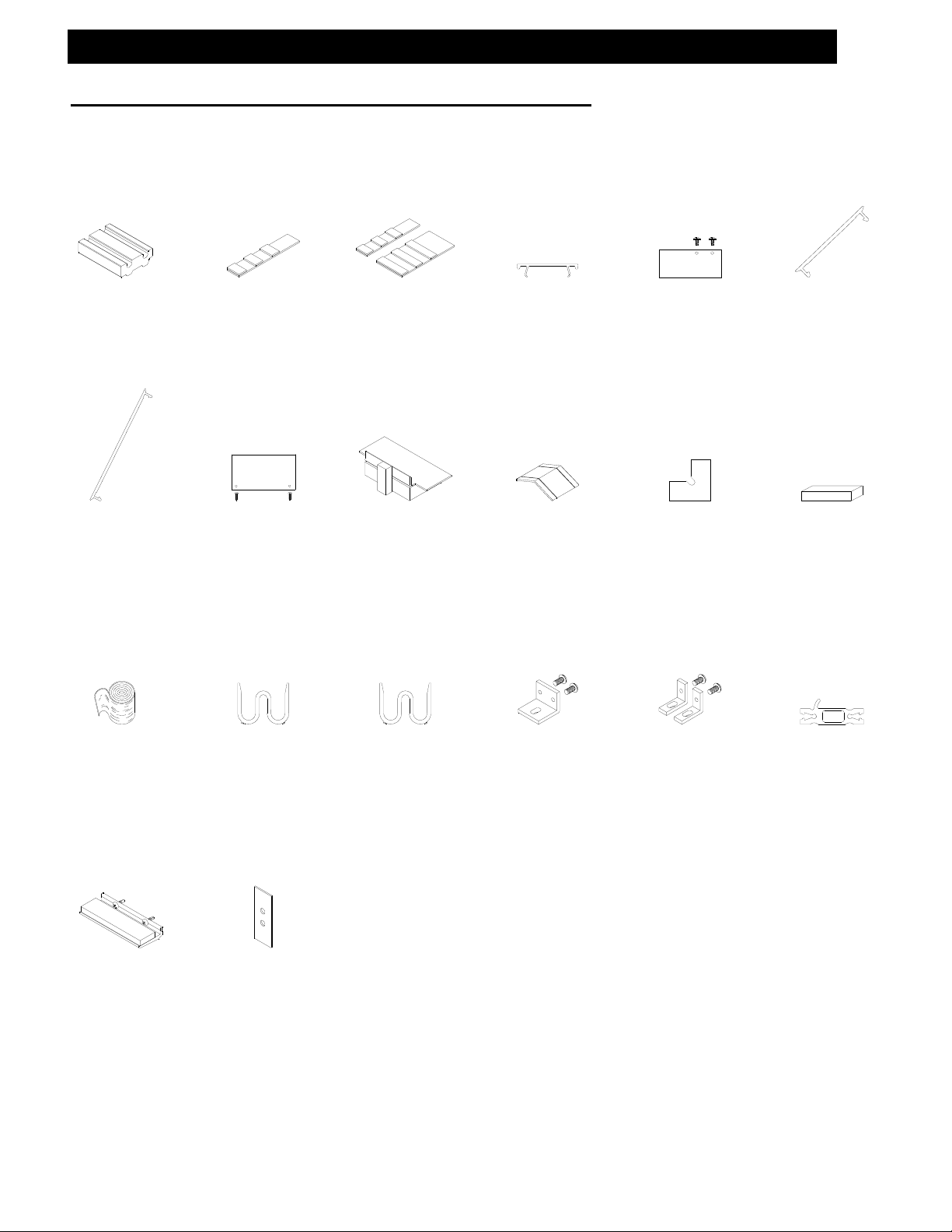
SECTION II: Parts Identification Chart
Vertical Parts:
8349
Offset Glazed Vertical
-Shear Block Only-
8353
Offset Glazed Vertical
Use w/8352
8352
Offset Glazed Vertical
Filler
Use w/8353
8354
Inside/Outside Offset
Vertical Half
Mates w/Itself
8356
Offset to Center-Set
Shallow Vertical Half
Use w/8359
8359
Center-Set to Offset
Deep Vertical Half
Use w/8356
8357
Center-Set Glazed
Vertical
-Shear Block Only-
8360
Center-Set to Center-Set
Shallow Vertical Half
Use w/8361
8396
Center Glaze Female
Expansion Mullion Half
Use w/8397
8394
Offset Glaze Female
Expansion Mullion Half
Use w/8395
8395
Offset Glaze Male
Expansion Mullion Half
Use w/8394
4470
Center Glaze Open Back
Sill/Vertical
4356
4 ½” Vertical
Mullion Half
4357
4 ½” Vertical Corner
4 ½” Single Pocket
Vertical Corner
June 2012 PART NO. Y017 Page 4 of 90
Drawings on this page are not to scale.
8355
Offset to Center-Set
Deep Vertical Half
Use w/8358
Center-Set to Offset
Shallow Vertical Half
Use w/8355
8361
Center-Set to Center-Set
Deep Vertical Half
Use w/8360
Offset Glaze Male
Expansion Mullion Half
4383
Screw Spline Sidelite
Door Jamb Deep Pocket
Filler Use w/4371 & 4372
Vertical Mullion Half
Shallow Pocket Non-
4358
8358
8397
Use w/8396
4393
Thermal
Page 5

Series 433 Triple Set Installation Instructions
SECTION II: Parts Identification Chart
Vertical Parts cont.:
Use w/8355, 8356 & 8361
8380
135 Corner Mullion
8439
Structural Glaze
Jamb w/Head & Sill
through
Structural Glaze
9838
Adjustable Sidelite
Dead Load Support Tube
8475
90 Structural Glaze Corner
Mullion
8389
Mullion
Structural Glaze Mullion
90 Corner Mullion
Use with
8355, 8356 & 8361
8387
Screw Spline
Use w/8388
Drawings on this page are not to scale.
8381
Out side to Inside Set
Expansion Mullion
Mates with Itself
8388
Screw Spline Structural
Glaze Mullion Filler
Use w/8387
Adjustable Sidelite
4380
16E1
Vertical
June 2012 PART NO. Y017 Page 5 of 90
Page 6

Series 433 Triple Set Installation Instructions
SECTION II: Parts Identification Chart
Horizontal Parts:
8363
Offset Intermediate
Horizoantal/Head
Use w/8365
8375
Center-Set Sill
Used @ 2S44 Subsill
8382
Head & Sill Face Cover
Use w/8384 & 8393
8365
Offset Glazing Bead
Use w/8363, 8385 & 8393
2S44
High Performance Subsill
Use w/8362 & 8375 Sills
4 ½” Horizontal for Center-
3G45
Set Outside Glazed
Offset Outside Set/ Outside
8366
Glazed, Inside Set/Inside Glazed
Horizontal/Head
Use w/8364 & 8367
8393
Structural Glaze Head
Use w/8365 & 8382
8386
Horizontal Face Cover
Use w/8385
8368
Center-Set Glazing Bead
Use w/8372
4471
Fill & Debridged Subsill
3G46
4 ½” Horizontal for Center-
Set Inside Glazed
8372
Center-Set Horizontal
Use w/8368
8385
Structural Glaze Horizontal
Use w/8365 & 8386
8367
Horizontal Face Snap
Use w/8366
E178
Frame Receptor Closer
Use w/1510
Center-Set Open Back Head
4 ½” Sill for Center-Set
Drawings on this page are not to scale.
8362
Offset Sill
Used @ 2S44 Subsill
8384
Structural Glaze Sill
Use w/8382
8364
Offset Horizontal Filler
Use w/8366
1510
Frame Receptor
Use w/E178
4369
3G48
Glazing
8746
Perimeter Adaptor
4G33
4 ½” Inside Set
Fixed Stop
June 2012 PART NO. Y017 Page 6 of 90
Page 7

Series 433 Triple Set Installation Instructions
SECTION II: Parts Identification Chart
Horizontal Parts:
16B9
4 ½” Offset Head & Sill
Face Cover
Use w/4G31
4G29
4 ½” Offset
Glazed Head
3S67
Adjustable Sidelite Sill
4G31
4 ½” Outside Set Sill
Use w/16B9
16B3
4 ½” Offset Intermediate
Horizontal Face Cover
Use w/4G30
4G32
4 ½” Outside Set Sill
Fixed Stop
16D9
Adjustable Sidelite
Horizontal
Drawings on this page are not to scale.
4G30
4 ½” Outside Set
Intermediate Horizontal
Use w/16B3
16C8
2-Part Perimeter
Interior Half
2-Part Perimeter
2-Part Mullion Half
16C9
Exterior Half
16C7
June 2012 PART NO. Y017 Page 7 of 90
Page 8

Series 433 Triple Set Installation Instructions
SECTION II: Parts Identification Chart
Door Frame Parts:
Drawings on this page are not to scale.
9209
Single Acting Door
Jamb
9208
Double Acting Door
Jamb
Door Jamb for Offset Glazing
Use 9154/9155 Door Stops
Use 8377/8378 Transom Stops
8374
4374
Offset Glazed Door Jamb
for Screw Spline Sidelites
4371
Standard Door Jamb for
Screw Spline Sidelites
Center Pivot Door Jamb
for Screw Spline Sidelites
Door Header @ Surface Closure
Use 4437/9155 Door Stop
8373
9234
Single Acting Door Header
Use 9123 for 1” Glass
9227
Dual Acting Door Header
Use 4437/9155 Door Stop
2556
2 X 4 ½ X 1/8” Wall Tube
Use 8377 & 8378 for Offset Glazing
@ C.O.C.
Use 4437/9155 Door Stop
8377
Applied Transom Glazing Stop
Use w/8378
8378
Transom Glass Stop
Use w/8377
9123
Transom Glazing Bead
Use w/9227 & 9234
9154
Applied Jamb Door Stop
Use w/9155 Cover
4437
Applied Head Door Stop
Use w/9155 Cover
Use w/9154 & 4437 Stops
9155
Door Stop Cover
9257
Snap-In Door Stop
Use w/ 8357
Snap-In Transom Glass Adapter
4376
Use w/9208 & 9209
Fasteners:
STV2
#14-10 X 1/2
HW-SMS 18-8 AB
STC8
#12-140 X 1 1/4
PH-SMS 18-8 TYPE 25
Assembly Screw
STD1
#12-24 X 1/2
TH-SMS 18-8
TYPE 23
STB9
#12-11 X 1/2
RH-SMS 18-8 A
STD8(Clr)/S117(Brz)
#10-12 X 3/4
FH-SMS 18-8 AB
STB5
#12-11 X 1 5/8
PH-SMS 18-8 A
June 2012 PART NO. Y017 Page 8 of 90
STT6
#8-18 X 9/16
PH-SMS 18-8 TEK
Door Stop/Transom Stop
Fastener
SPZ1
#8-18 X 3/4
PH-SMS 18-8 AB
Adjustable Sidelite
Assembly Fastener
FW95
3" Rod for Horizontal
Dead Load Support
at Intermediate Vert.
FW96
2" Rod for Horizontal
Dead Load Support
at Perimeter Vert.
4372
Page 9

,
,
Series 433 Triple Set Installation Instructions
SECTION II: Parts Identification Chart
Shear Blocks:
LH or RH C.O.C. Header Shear Block
Pkg. for Pivots, Butts or Cont. Hinge
Use w/ 9227
K918
9234 or 2556
Shear Block Pkg. for Offset
Use w/8363,8366
K925
Horizontal/Head
8385 or 8393
RH STD Door Header Shear Block Pkg.
K919
for Pivots, Butts or Cont. Hinge
Use w/8373
K926
Shear Block Pkg. for
Center-Set Sill
Use w/8375
Drawings on this page are not to scale.
K923
LH STD Door Header Shear Block Pkg.
for Pivots, Butts or Cont. Hinge
Use w/8373
K927
Shear Block Pkg. For
Offset Sill
Use w/8362 & 8384
Use (2) w/4G31, 4G32 & 4G33
Shear Block Pkg. for Center-
K924
Set Horizontal/Head
Use w/8372
KN52
Shear Block Pkg. for 90 Structural
Glaze Corner @ Head/ Horizontal
Use w/8475
KN53
Shear Block Pkg. for 90
Structural Glaze Corner @ Sill
Use w/8475
Shear Block Pkg. for Offset
KN73
Vertical to Horizontal thru
Attachment
Setting Blocks:
HN64
Setting Block @ Adjustable
Sidelite Horizontal (16D9)
KN67
Shear Block Pkg. for
Center Set Head
Use w/4369
KN74
Shear Block Pkg. for Center Set
Vertical to Horizontal thru
Attachment
HN38
Setting Block @ Applied
Transom Glass Stops 8377 &
8378
KN91
Shear Block Pkg. for 4 ½”
Horizontal/Head
Use w/4G30 & 4G29
HN32
Setting Block @ Sill
(or Applied Transom Glass
Stops 9123)
KN69
Shear Block Pkg. for 4 ½”
Center-Set Horizontal/Head
Use w/3G45
HN92
Setting Block @ Horizontals
(including 8373 Door Header)
KN92
Shear Block Pkg. for
2-Piece Rolld Horizontal
June 2012 PART NO. Y017 Page 9 of 90
Page 10

(
)
Series 433 Triple Set Installation Instructions
SECTION II: Parts Identification Chart
Glazing Gaskets:
W164
Standard Glazing Gasket
1” Infill @ 1” Pocket
W115
Glazing Gasket for 2Piece Rolled Framing
@ 1” Pocket
Weather Seals:
WA04
Standard Weather Seal
@ Subframes 1510 & E178
W166
Glazing Gasket for
Oversized Glass 1 1/16”
Infill @ 1” Pocket
WM10
Tape for 90・・・・・
SSG Mullion
WQ02
Optional Weather Seal
@ Subframes 1510 & E178
W165
Glazing Gasket for
Undersized Glass 3/4” Infill
@ 1” Pocket
W161
Adjustable Sidelite
Gasket at Sill
Standard Weather Seal
@ Door Stops
W138
Drawings on this page are not to scale.
W166/W164
Glazing Gasket for Undersized
Glass 7/8”-15/16” Infill @ 1”
Pocket-Use W165 Exterior
and W164 Interior
W104
Standard Weather Seal
@ Expansion Mullion and
Adjustable Sidelite
WM80
SSG Mullions
Tape for
Drill Jigs:
DJ12
Offset Glazing Head &
Horizontal Drill Fixture
Shear Block Drill Fixture for
4 ½” Center-Set Horizontals
DJ23
DJ13
Offset & Center-Set
Sill Drill Fixture
DJ24
Screw Spline Drill Fixture for
4 ½” Offset Horizontals
Shear Block Drill Fixture for
DJ14
Vertical Fabrication
DJ25
Shear Block Drill Fixture for
4 ½” Center Set & Offset
Horizontals
Screw Spline Drill Fixture for
DJ15
Vertical Fabrication
Shear Block Drill Fixture for
DJ22
Dead Load Support Pin
Drill Fixture
DJ26
4 ½” Horizontals
Center-Set & Offset
June 2012 PART NO. Y017 Page 10 of 90
Page 11
Series 433 Triple Set Installation Instructions
SECTION II: Parts Identification Chart
Misc. Parts:
HN44
Head & Sill Foam
Splice Joint
LB90
Vinyl Center-Set Pocket
Filler @ Perimeter
Condition
Use W/8355, 8356, 8361
K898
Sill Splice Plates (2)
per Splice Required
K941
Subsill End-Dam
Package
Use w/2S44 Subsill
K898/K897
Head Splice Plates
K895
Horizontal Bridge
Assembly
LB77
Vinyl Pocket Filler
Glass Pockets @
Perimeter Condition
HWD1
Water Deflector @
Intermediate Horizontal
Drawings on this page are not to scale.
KN11
Structural Glaze
Head End-Dam
Package
FW33
90 Structural
Glaze Corner
Water Diverter
LB89
Vinyl Offset Pocket
Filler @ Perimeter
Condition
Use W/8353
HCW6
Weep Baffle used
@ Subsill
WM01
Bond Breaker Tape
4” X .062”
Used @ Subsill Splices
KN93
2-Piece Rolled
Horizontal Setting
Chair
Use w/ 16C9 & 16C7
HN50
1/2” Anti Walk Block
Use w/8349, 8353,
8357 & 8361
FWB6
Adjustable Side Lite
Dead Load Support
Tube Washer
HN52
5/8” Anti Walk Block
Use w/8354, 8355,
& 8359
K473
Vertical Anchor
Package Used with
Offset Glazed
Verticals
K992
Vertical Anchor
Package Used with
Center-Set Glazed
Verticals
H260
2-Piece Rolled/Slope
Frame Clips
June 2012 PART NO. Y017 Page 11 of 90
Page 12
Series 433 Triple Set Installation Instructions
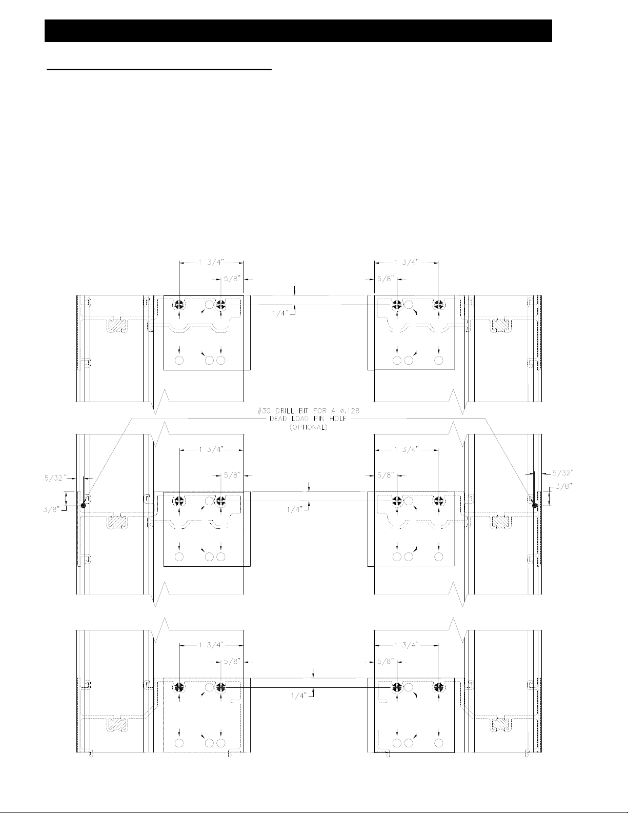
SECTION III: Fabrication
A. Drilling Template Offset Screw Spline Verticals (Offset Mullion)
Left Hand Mullion Shown, Right Hand Opposite
Use the exterior edge of the vertical to align Drill Jig DJ15. Use .221 dia. (#2) drill at
darkened areas only.
These preps work for both inside and outside glazed versions.
Outside Set Mullion Inside Set Mullion
OFF SET
433 S.S.
DJ15
OFF SET
CENTER SET
OFF SET
DJ15
433 S.S.
CENTER SET
OFF SET
OFF SET
433 S.S.
OFF SET
CENTER SET
OFF SET
DJ15
433 S.S.
DJ15
CENTER SET
OFF SET
CENTER SET
OFF SET
OFF SET
CENTER SET
OFF SET
OFF SET
DJ15
433 S.S.
433 S.S.
DJ15
June 2012 PART NO. Y017 Page 12 of 90
Page 13

Series 433 Triple Set Installation Instructions
SECTION III: Fabrication
A. Drilling Template Offset Screw Spline Verticals (Offset Mullion Filler)
Left Hand Mullion Filler Shown, Right Hand Opposite
Use the exterior edge of the vertical to align Drill Jig DJ15. Use .221 dia. (#2) drill at
darkened areas only.
These preps work for both inside and outside glazed versions.
Outside Set Mullion Inside Set Mullion
CENTER SET
OFF SET
433 S.S.
OFF SET
DJ15
DJ15
433 S.S.
OFF SET
OFF SET
CENTER SET
CENTER SET
OFF SET
433 S.S.
OFF SET
DJ15
DJ15
433 S.S.
OFF SET
OFF SET
CENTER SET
OFF SET
CENTER SET
433 S.S.
OFF SET
DJ15
DJ15
433 S.S.
OFF SET
OFF SET
CENTER SET
June 2012 PART NO. Y017 Page 13 of 90
Page 14
Series 433 Triple Set Installation Instructions
SECTION III: Fabrication
A. Drilling Template Offset Screw Spline Verticals (Offset Mullion)
with 4 ½” Horizontals
Left Hand Mullion Shown, Right Hand Opposite
Use the exterior edge of the vertical to align Drill Jig DJ25. Use .221 dia. (#2) drill at
darkened areas only.
These preps work for both inside and outside glazed versions.
CENTER SET
OFF SET
OFF SET
OFF SET
OFF SET
CENTER SET
433 S.S.
OFF SET
DJxx
CENTER SET
OFF SET
433 S.S.
DJxx
OFF SET
OFF SET
CENTER SET
CENTER SET
OFF SET
OFF SET
OFF SET
OFF SET
CENTER SET
June 2012 PART NO. Y017 Page 14 of 90
Page 15
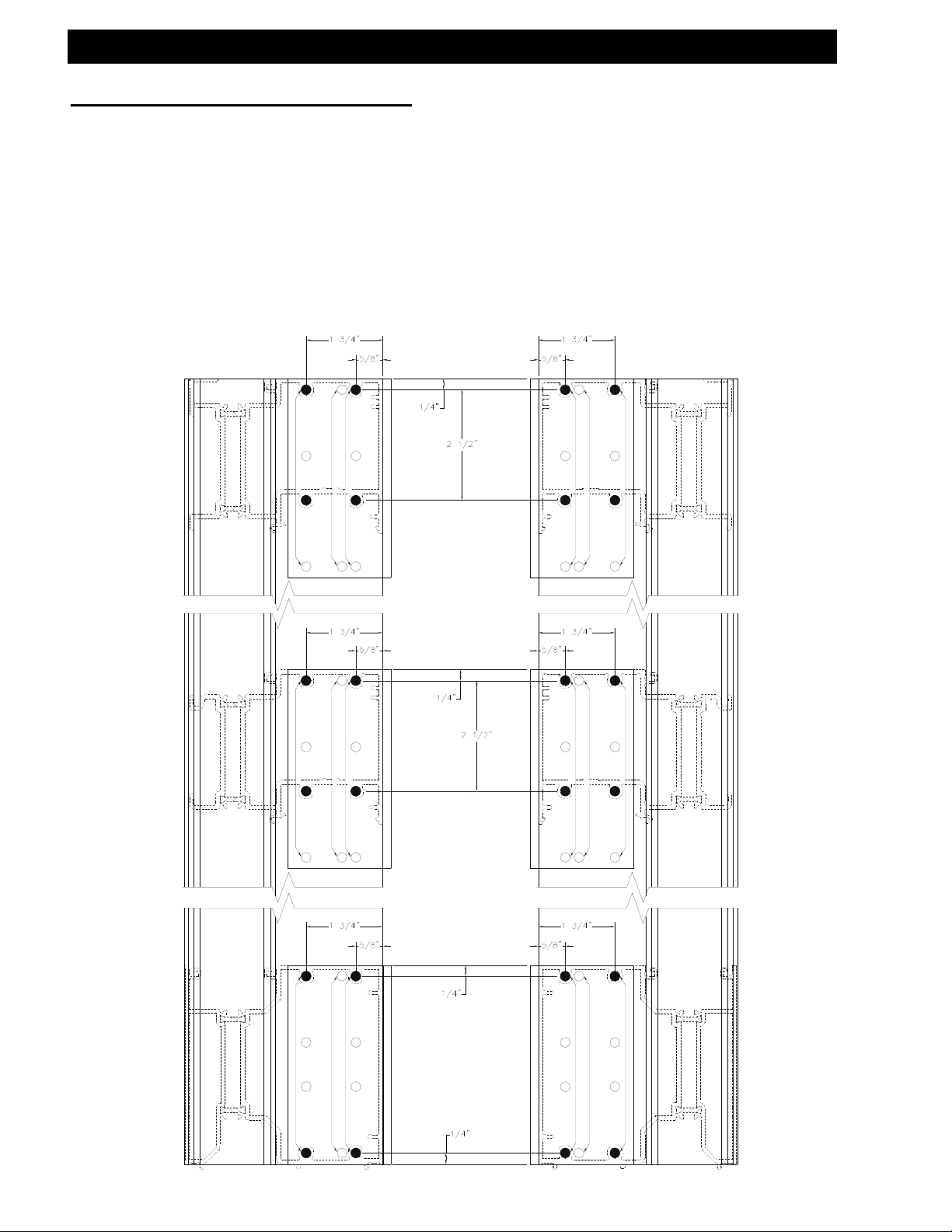
Series 433 Triple Set Installation Instructions
SECTION III: Fabrication
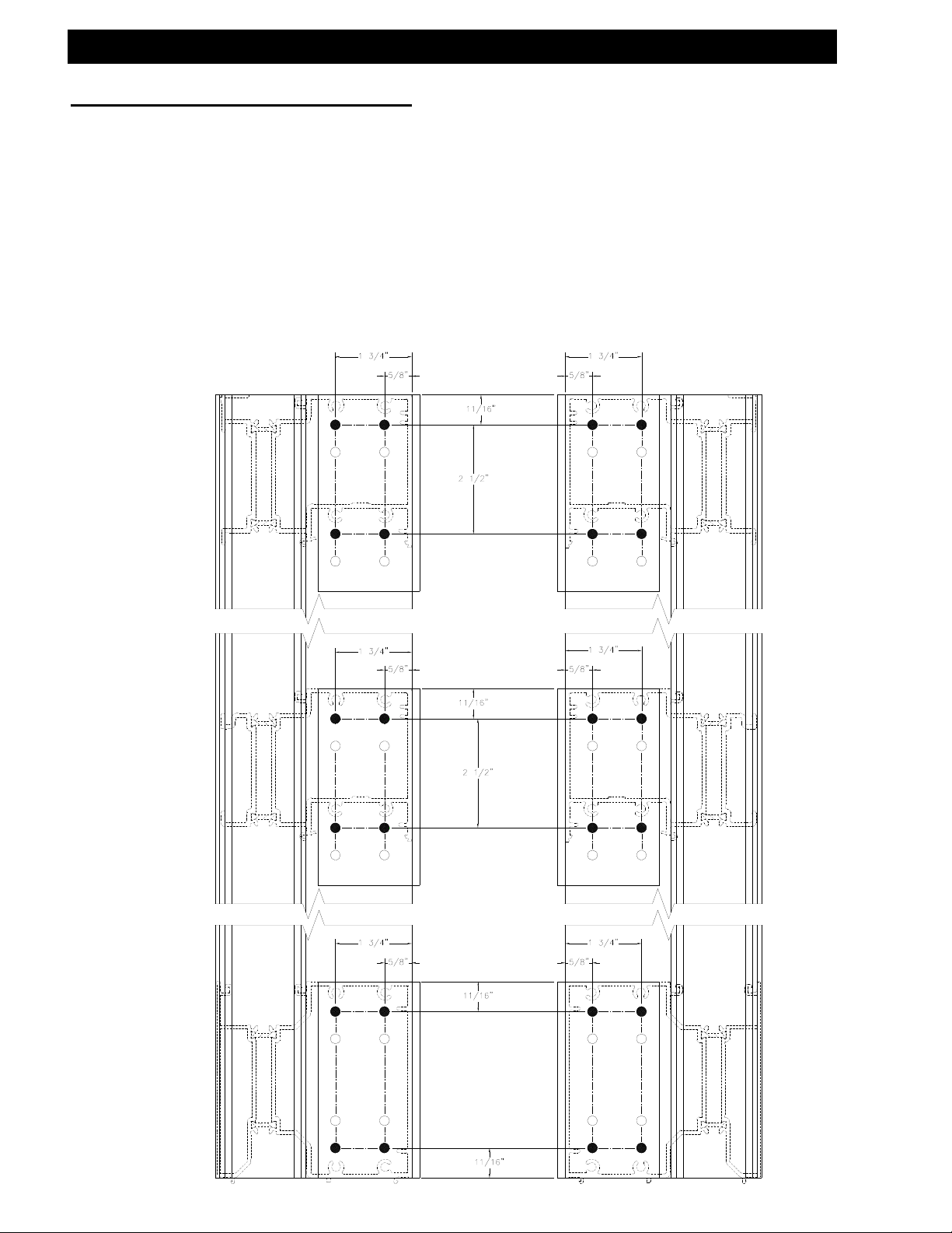
B. Drilling Template Offset Shear Block Verticals (Offset Mullion)
Left Hand Mullion Shown, Right Hand Opposite
Use the exterior edge of the vertical to align Drill Jig DJ14. Use .182 dia. (#14) drill at
darkened areas only.
These preps work for both inside and outside glazed versions.
5/32"
3/8"
June 2012 PART NO. Y017 Page 15 of 90
Outside Set Mullion Inside Set Mullion
1 3/4"
5/8"
11/16"
11/16"
1 3/4"
5/8"
CENTER SET
OFF SET
CENTER SET
433 S.B.
DJ14
433 S.B.
DJ14
CENTER SET
OFF SET
CENTER SET
1 3/4"
5/8"
11/16"
11/16"
1 3/4"
5/8"
CENTER SET
OFF SET
CENTER SET
433 S.B.
DJ14
433 S.B.
DJ14
CENTER SET
OFF SET
CENTER SET
5/8"
433 S.B.
DJ14
1 3/4"
CENTER SET
OFF SET
CENTER SET
CENTER SET
1 3/4"
OFF SET
5/8"
11/16"
11/16"
433 S.B.
DJ14
CENTER SET
5/32"
3/8"
Page 16

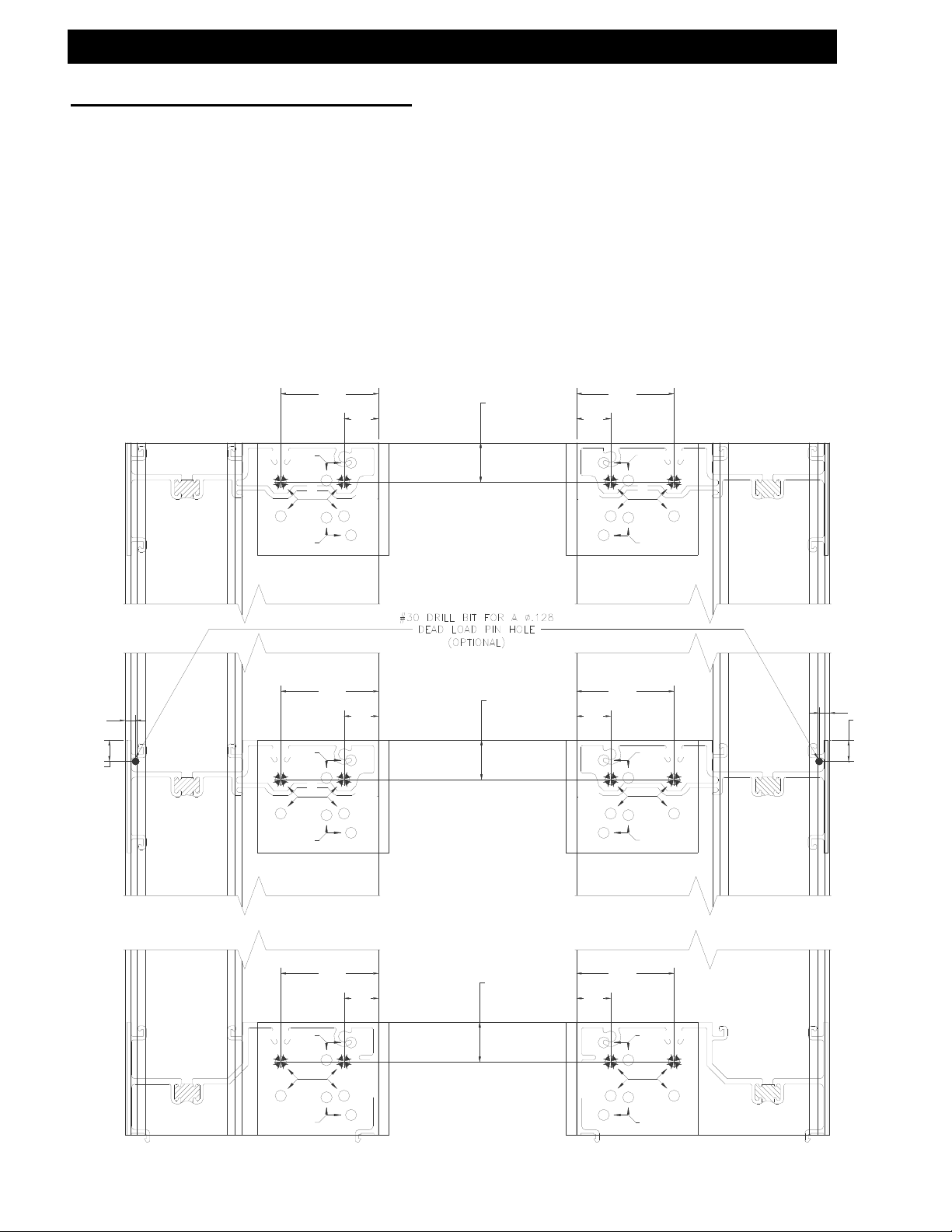
Series 433 Triple Set Installation Instructions
SECTION III: Fabrication
B. Drilling Template Offset Shear Block Verticals (Offset Mullion Filler)
Left Hand Mullion Shown, Right Hand Opposite
Use the exterior edge of the vertical to align Drill Jig DJ14. Use .182 dia. (#14) drill at
darkened areas only.
These preps work for both inside and outside glazed versions.
June 2012 PART NO. Y017 Page 16 of 90
Outside Set Mullion Filler Inside Set Mullion Filler
CENTER SET
OFF SET
CENTER SET
433 S.B.
DJ14
433 S.B.
DJ14
CENTER SET
OFF SET
CENTER SET
CENTER SET
OFF SET
CENTER SET
433 S.B.
433 S.B.
DJ14
CENTER SET
OFF SET
CENTER SET
CENTER SET
OFF SET
CENTER SET
433 S.B.
DJ14DJ14
433 S.B.
DJ14
CENTER SET
OFF SET
CENTER SET
Page 17
Series 433 Triple Set Installation Instructions
SECTION III: Fabrication
B. Drilling Template Offset Shear Block Verticals (Offset Mullion)
with 4 ½” Horizontals
Left Hand Mullion Shown, Right Hand Opposite
Use the exterior edge of the vertical to align Drill Jig DJ24. Use .182 dia. (#14) drill at
darkened areas only.
These preps work for both inside and outside glazed versions.
Outside Set Mullion Inside Set Mullion
June 2012 PART NO. Y017 Page 17 of 90
Page 18
Series 433 Triple Set Installation Instructions
SECTION III: Fabrication
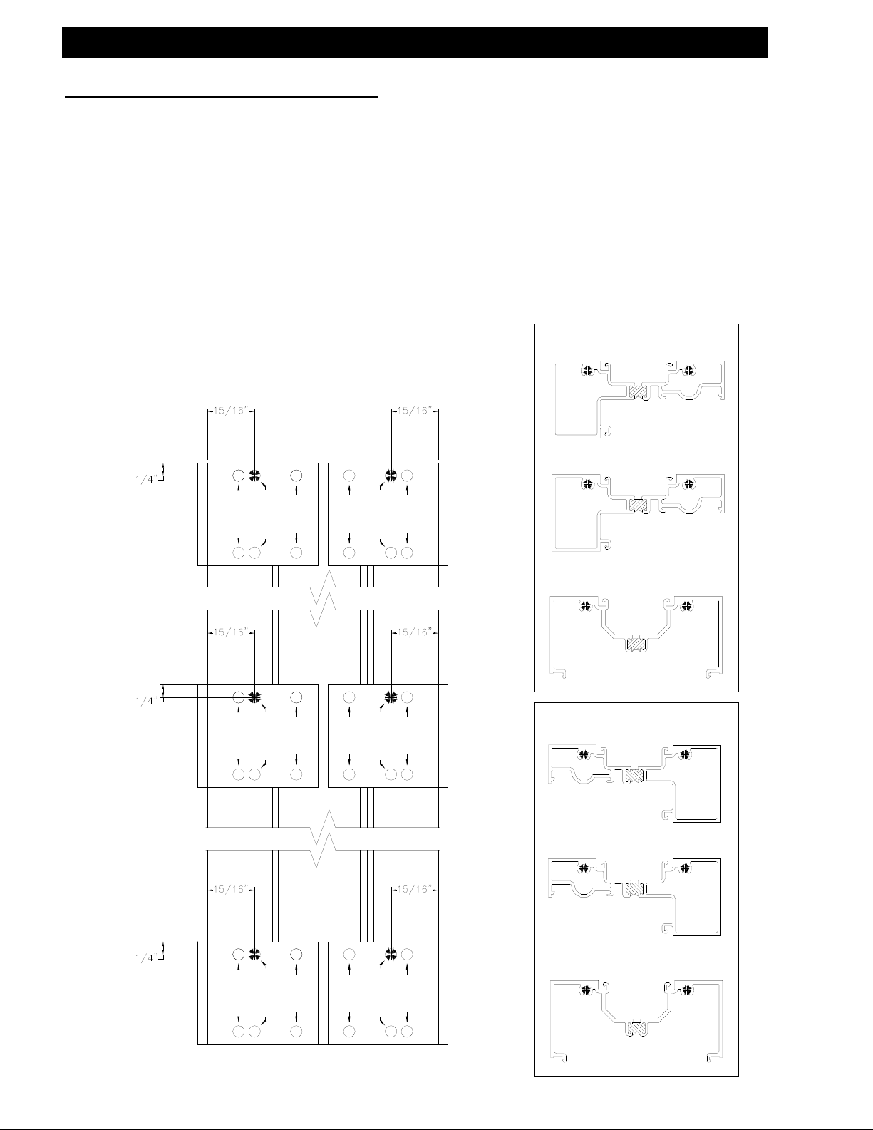
C. Drilling Template Center-Set Screw Spline Verticals (Center-Set Mullion)
Left Hand Mullion Shown, Right Hand Opposite
Use the exterior edge of the vertical to align Drill Jig DJ15. Use .221 dia. (#2) drill at
darkened areas only.
These preps work for both inside and outside glazed versions.
Center-Set Mullion
(Reverse Drill Jig for
the opposite side)
Inside Glazed
CENTER SET
OFF SET
DJ15
433 S.S.
OFF SET
CENTER SET
OFF SET
OFF SET
433 S.S.
DJ15
DJ15
433 S.S.
OFF SET
OFF SET
CENTER SET
CENTER SET
OFF SET
OFF SET
433 S.S.
DJ15
Outside Glazed
DJ15
433 S.S.
OFF SET
OFF SET
CENTER SET
OFF SET
CENTER SET
OFF SET
DJ15
433 S.S.
June 2012 PART NO. Y017 Page 18 of 90
Page 19
Series 433 Triple Set Installation Instructions
SECTION III: Fabrication
C. Drilling Template Center-Set Screw Spline Verticals (Center-Set Mullion)
with 4 ½” Horizontals
Left Hand Mullion Shown, Right Hand Opposite
Use the exterior edge of the vertical to align Drill Jig DJ25. Use .221 dia. (#2) drill at
darkened areas only.
These preps work for both inside and outside glazed versions.
Center-Set Mullion
(Reverse Drill Jig for
the opposite side)
Inside Glazed Outside Glazed
OFF SET
OFF SET
CENTER SET
OFF SET
CENTER SET
OFF SET
CENTER SET
OFF SET
CENTER SET
OFF SET
OFF SET
OFF SET
CENTER SET
OFF SET
OFF SET
OFF SET
CENTER SET
OFF SET
June 2012 PART NO. Y017 Page 19 of 90
Page 20

Series 433 Triple Set Installation Instructions
SECTION III: Fabrication
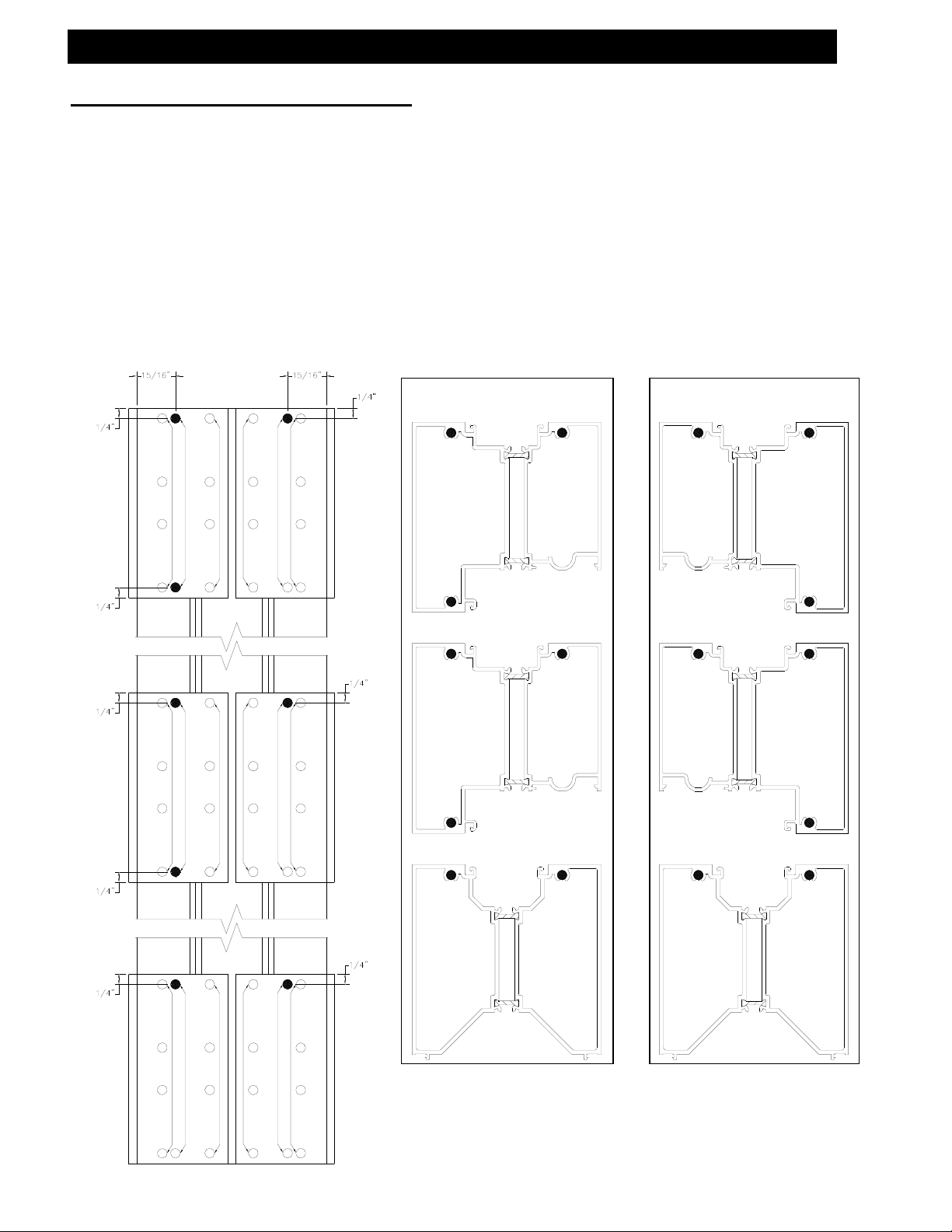
D. Drilling Template Center-Set Shear Block Verticals (Center-Set Mullion)
Left Hand Mullion Shown, Right Hand Opposite
Use the exterior edge of the vertical to align Drill Jig DJ14. Use .182 dia. (#14) drill at
darkened areas only.
These preps work for both inside and outside glazed versions.
June 2012 PART NO. Y017 Page 20 of 90
Center-Set Mullion
(Reverse Drill Jig for
the opposite side)
Inside Glazed
CENTER SET
DJ14
433 S.B.
OFF SET
CENTER SET
CENTER SET
OFF SET
CENTER SET
DJ14
433 S.B.
CENTER SET
DJ14
433 S.B.
OFF SET
CENTER SET
OFF SET
CENTER SET CENTER SET
433 S.B.
DJ14
Outside Glazed
CENTER SET
DJ14
433 S.B.
OFF SET
CENTER SET
OFF SET
CENTER SET CENTER SET
DJ14
433 S.B.
Page 21
Series 433 Triple Set Installation Instructions
SECTION III: Fabrication
D. Drilling Template Center-Set Shear Block Verticals (Center-Set Mullion)
with 4 ½” Horizontals
Left Hand Mullion Shown, Right Hand Opposite
Use the exterior edge of the vertical to align Drill Jig DJ23. Use .182 dia. (#14) drill at
darkened areas only.
These preps work for both inside and outside glazed versions.
Center-Set Mullion
(Reverse Drill Jig for
the opposite side)
Inside Glazed Outside Glazed
June 2012 PART NO. Y017 Page 21 of 90
Page 22
(2)
Series 433 Triple Set Installation Instructions
SECTION III: Fabrication
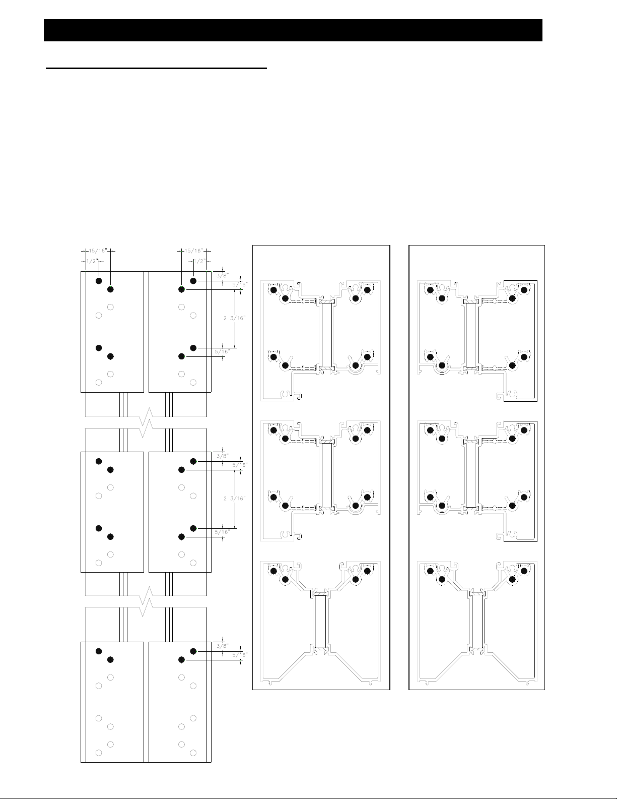
D. Drilling Template Center-Set Shear Block Verticals & Horizontals
(2-Piece Slope or Arch Top)
Left Hand Mullion Shown, Right Hand Opposite
preps work for both inside and
Vertical Fabrication:
Outside Glazed Shown
Inside Opposite
Use .147 dia. (#26) drill at
darkened areas only. These
outside glazed versions.
Horizontal Fabrication
3/16” Dia. Thru Hole
#8 Flat Head Screw
(1) Wall.
Countersink For
Thru (1) Wall
Holes Each End
June 2012 PART NO. Y017 Page 22 of 90
Page 23

Series 433 Triple Set Installation Instructions
SECTION III: Fabrication
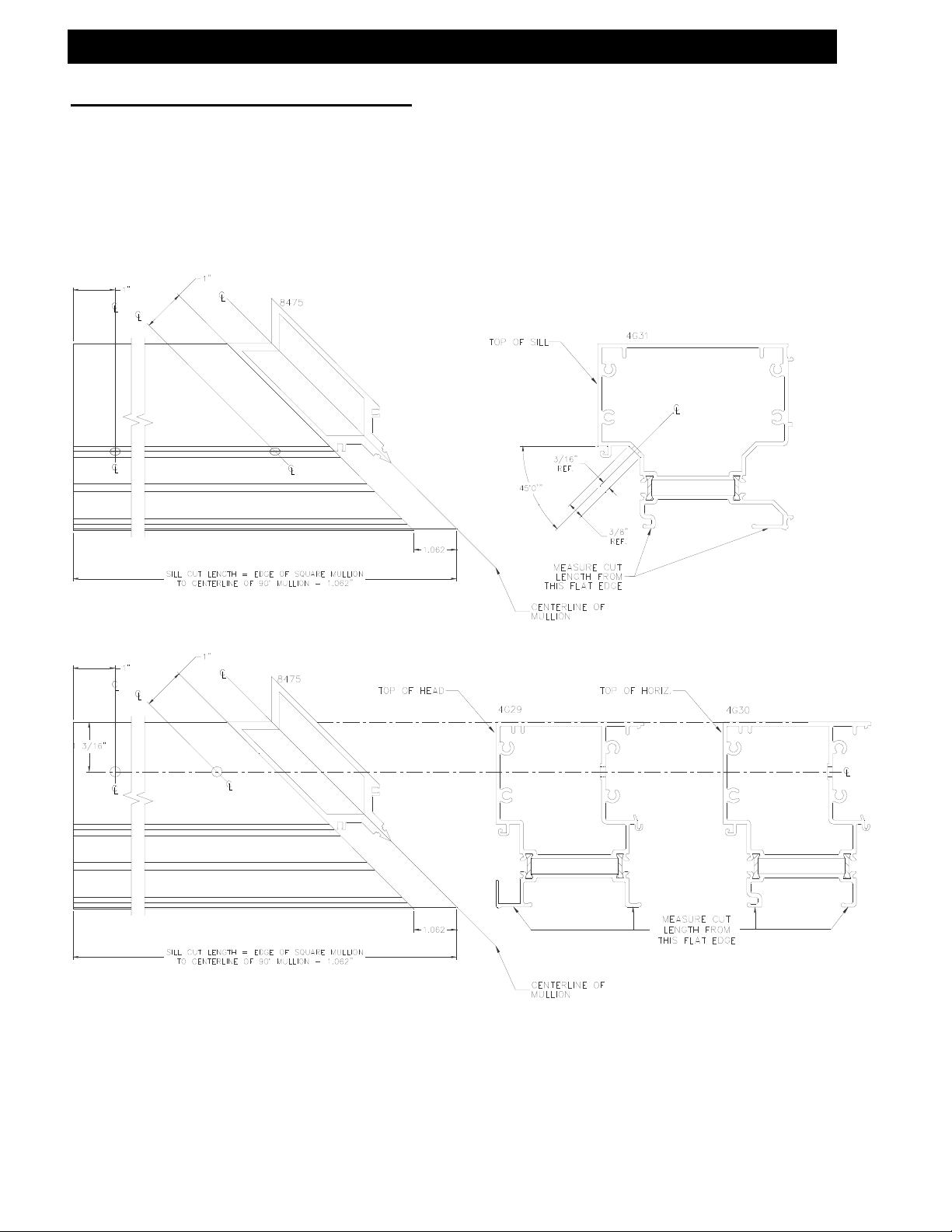
E. Drilling Template Offset @ 90° Corner Horizontal/Head/Sill
8475
Use .246 Diameter
(#D) Drill Bit
TOP OF
SILL
8384
MEASURE CUT
LENGTH FROM
THIS FLAT EDGE
CENTERLINE OF
MULLION
8475
TOP OF
HEAD
8393
TOP OF
HORIZ.
8385
CENTERLINE OF
MULLION
MEASURE CUT
LENGTH FROM
THIS FLAT EDGE
June 2012 PART NO. Y017 Page 23 of 90
Page 24
Series 433 Triple Set Installation Instructions
SECTION III: Fabrication
E. Drilling Template Offset @ 90° Corner Horizontal/Head/Sill
4 ½” Horizontals
Use .246 Diameter
(#D) Drill Bit
June 2012 PART NO. Y017 Page 24 of 90
Page 25
(Typ. at each end)
Series 433 Triple Set Installation Instructions
SECTION III: Fabrication
F. Drilling Template for Offset and Center-Set Shear Block at Sills
1" 1"
June 2012 PART NO. Y017 Page 25 of 90
Fixture DJ13 should be placed at the end of the sills as
shown. These preps work on all offset and center-set sills.
Use .246 Diameter (#D) Drill Bit
1" 1"
Drill one side and flip the fixture to drill the opposite side.
CENTER THE .246
DIA. HOLE AT
MIDPOINT OF FLAT
DJ13
(Typ. at each end)
FU19
DJ13
FU19
8372
45°
8362
FU20
8372
FU19
DJ13
FU19
Page 26
Series 433 Triple Set Installation Instructions
SECTION III: Fabrication
F. Drilling Template for Offset and Center-Set Shear Block at 4 ½” Sills
Fixture DJ13 should be placed at the end of the sills as
shown. These preps work on all offset and center-set sills.
1" 1"
Use .246 Diameter (#D) Drill Bit
CENTER THE .246
DIA. HOLE AT
MIDPOINT OF FLAT
4G33
DJ13
FU20
45°
FU20
1" 1"
DJ13
(Typ. at each end)
3G48
FU19
FU19
3G48
FU19
DJ13
FU19
June 2012 PART NO. Y017 Page 26 of 90
Page 27
Series 433 Triple Set Installation Instructions
SECTION III: Fabrication
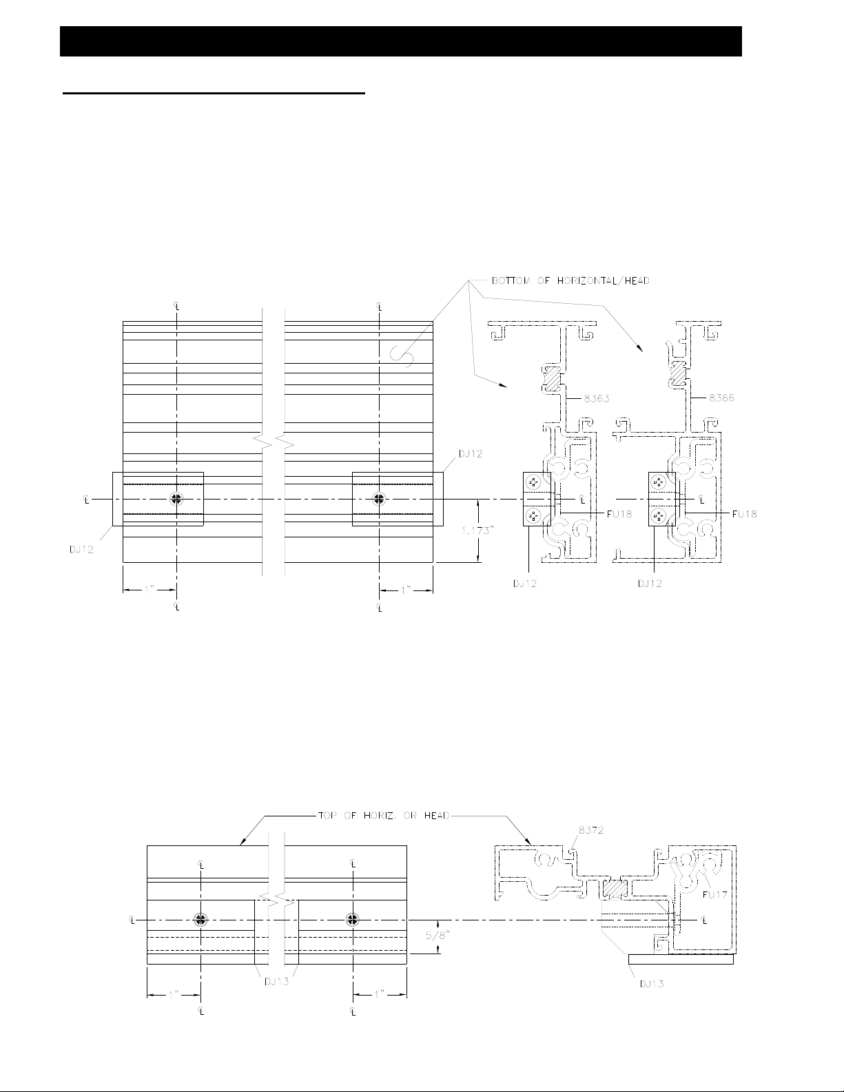
G. Drilling Template Offset and Center-Set Shear Block at Horizontals
June 2012 PART NO. Y017 Page 27 of 90
Fixture DJ12 is self-aligning and should be placed at the end
of the horizontal as shown. These preps work on all offset
head and intermediate horizontals.
Use .246 Diameter (#D) Drill Bit
Fixture DJ13 should be placed at the end of the horizontal as
shown. These preps work on all center-set head and
intermediate horizontals.
Use .246 Diameter (#D) Drill Bit
Page 28

Series 433 Triple Set Installation Instructions
SECTION III: Fabrication
G. Drilling Template Offset and Center-Set Shear Block at 4 ½” Horiz.
Fixture DJ26 is self-aligning and should be placed at the end
of the horizontal as shown. These preps work on all offset
head and intermediate horizontals.
Use .246 Diameter (#D) Drill Bit
Fixture DJ26 should be placed at the end of the horizontal as
shown. These preps work on all center-set head and
intermediate horizontals.
Use .246 Diameter (#D) Drill Bit
June 2012 PART NO. Y017 Page 28 of 90
Page 29

Series 433 Triple Set Installation Instructions
SECTION III: Fabrication
H. Drilling Template Offset Glazed Head & Sill Through
June 2012 PART NO. Y017 Page 29 of 90
Head and Sill through Butt Glazed Jamb and Vertical
Use the exterior edge of the jamb or vertical to align
drill jig DJ15.
Use .221 diameter (#2) drill bit at darkened areas only.
Page 30

Series 433 Triple Set Installation Instructions
SECTION III: Fabrication
H. Drilling Template Offset Screw Spline SSG Verticals for Intermediate
Horizontal with Head & Sill Through
Use the exterior edge of the vertical to align Drill Jig DJ15 for 2” mullions and DJ25 for
4 ½” mullions. Use .221 dia. (#2) drill at darkened areas only.
CENTER SET
OFF SET
433 S.S.
OFF SET
DJ15
CENTER SET
OFF SET
OFF SET
8387
8388
8387
8388
June 2012 PART NO. Y017 Page 30 of 90
Page 31

Series 433 Triple Set Installation Instructions
SECTION III: Fabrication
H. Drilling Template Offset Shear Block SSG Verticals for Intermediate
Horizontal with Head & Sill Through
Use the exterior edge of the vertical to align Drill Jig DJ14 for 2” mullions and DJ24 for
4 ½” mullions. Use .201 dia. (#7) drill at darkened areas only.
CENTER SET
OFF SET
DJ14
433 S.B.
CENTER SET
8389
8389
June 2012 PART NO. Y017 Page 31 of 90
Page 32

Series 433 Triple Set Installation Instructions
SECTION IV: Unit Assembly
A. Screw Spline (Offset and Center-Set)
Note: Clean off all
excess sealant after
assembly.
Offset Glazed Assembly
Outside Set, Inside glazed shown,
Outside Set, Outside Glazed Similar
Note: Wax Type Lubricate may be
required @ Assembly Fasteners
4 ½” Head,
Horizontal &
Sill Similar
June 2012 PART NO. Y017 Page 32 of 90
Page 33

a
Series 433 Triple Set Installation Instructions
SECTION IV: Unit Assembly
A. Screw Spline (Offset and Center-Set)
Offset Glazed Assembly
Inside Set, Outside glazed shown,
Inside Set, Inside Glazed Similar
Note: Wax Type Lubricate may be
required @ Assembly Fasteners
Note: Clean off all
excess sealant after
assembly.
4 ½” Head,
Horizontal &
Sill Similar
Butter the ends fo all horizontals with se
June 2012 PART NO. Y017 Page 33 of 90
Page 34

Series 433 Triple Set Installation Instructions
June 2012 PART NO. Y017 Page 34 of 90
Page 35

Series 433 Triple Set Installation Instructions
SECTION IV: Unit Assembly
A. Screw Spline (Offset and Center-Set)
8361 SHOWN
(8358, 8359 SIM.)
June 2012 PART NO. Y017 Page 35 of 90
EXTERIOR FACE
Note: Clean off all
excess sealant after
assembly.
Center Glazed Assembly
Inside Glazed
Note: Wax Type Lubricate may be
required @ Assembly Fasteners
4 ½” Head,
Horizontal &
Sill Similar
BUTTER THE ENDS OF ALL
HORIZONTALS WITH BUTYL TYPE
SEALANT AS SHOWN BY THE
SHADED AREAS PRIOR TO
ASSEMBLY OF THE UNITS.
STC8
STC8
STC8
8360
Page 36

Series 433 Triple Set Installation Instructions
SECTION IV: Unit Assembly
A. Screw Spline (Offset and Center-Set)
Note: Clean off all
excess sealant after
assembly.
Offset Structural Glazed Assembly
HORIZONTALS WITH BUTYL TYPE
STC8
8355
8384
BUTTER THE ENDS OF ALL
SEALANT AS SHOWN BY THE
SHADED AREAS PRIOR TO
ASSEMBLY OF THE UNITS.
Note: Wax Type Lubricate may be
required @ Assembly Fasteners
Details shown without removable
face for clarity.
8393
8387
8385
4 ½” Head,
Horizontal &
Sill Similar
STC8
STC8
8388
8393
8385
8384
June 2012 PART NO. Y017 Page 36 of 90
Page 37

Series 433 Triple Set Installation Instructions
SECTION IV: Unit Assembly
A. Screw Spline (Offset and Center-Set)
Note: Clean off all
excess sealant after
assembly.
Offset Glazed Assembly With Expansion Mullion
Outside Set, Inside Glazed Shown,
Outside Set, Outside Glazed Similar
4 ½” Head,
Horizontal, &
Sill Similar
Note: Wax Type Lubricate may be
required @ Assembly Fasteners.
Expansion mullions are required in elevations that are over 20’-25’ wide
and can be used with both screw spline and shear block systems.
June 2012 PART NO. Y017 Page 37 of 90
Page 38

Series 433 Triple Set Installation Instructions
SECTION IV: Unit Assembly
A. Screw Spline (Offset and Center-Set)
Center Glazed Assembly With Expansion Mullion
Inside Glazed
4 ½” Head,
Horizontal, &
Sill Similar
Note: Wax Type Lubricant may be
required @ Assembly Fasteners.
EXTERIOR FACE
Note: Clean off all
excess sealant after
assembly.
BUTTER THE ENDS OF ALL
HORIZONTALS WITH BUTYL TYPE
SEALANT AS SHOWN BY THE
SHADED AREAS PRIOR TO
ASSEMBLY OF THE UNITS.
Expansion mullions are required in elevations that are over 20’-25’ wide
and can be used with both screw spline and shear block systems.
June 2012 PART NO. Y017 Page 38 of 90
Page 39

Series 433 Triple Set Installation Instructions
SECTION IV: Unit Assembly
A. Screw Spline (Offset and Center-Set)
Use FW95 3” Dead Load Support Pin when
there is a Horizontal member on both
sides of the Transom Jamb or Vertical.
Dead Load Pin Installation
Outside Set Shown
Use FW96 2” Dead Load Support Pin when
there is a Horizontal member on one side
of the Vertical or for Door Jambs with side
lites.
4374
8353
8354 8356
8355 8374
DIES SIMILAR TO
ONE’S SHOWN.
June 2012 PART NO. Y017 Page 39 of 90
Page 40

Series 433 Triple Set Installation Instructions
SECTION IV: Unit Assembly
B. Shear Block (Offset and Center-Set)
Note: Clean off all
excess sealant after
assembly.
June 2012 PART NO. Y017 Page 40 of 90
4 ½” Head,
Horizontal &
Sill Similar
EXTERIOR FACE
Offset Glazed Assembly
Inside Set, Inside Glazed shown,
Other Glazing Variations Similar
K925
KN91 (4 ½”)
Note: Wax Type Lubricate may be
required @ Assembly Fasteners
K925
KN91 (4 ½”)
K927
K927 (4 ½”)
K925
KN91 (4 ½”)
8362
K927
K927 (4 ½”)
Shear block packages
come with all required
fasteners.
BUTTER THE ENDS OF ALL
HORIZONTALS WITH BUTYL TYPE
SEALANT AS SHOWN BY THE
SHADED AREAS PRIOR TO
ASSEMBLY OF THE UNITS.
K925
KN91 (4 ½”)
Page 41

Series 433 Triple Set Installation Instructions
SECTION IV: Unit Assembly
B. Shear Block (Offset and Center-Set)
8359 SHOWN
(8357, 8360,
8361 SIM.)
June 2012 PART NO. Y017 Page 41 of 90
4 ½” Head,
Horizontal &
Sill Similar
EXTERIOR FACE
Note: Clean off all
excess sealant after
assembly.
Center-Set Glazed Assembly
Inside Glazed shown,
Outside Glazed similar
K924
KN69 (4 ½”)
K924
KN69 (4 ½”)
K926
K926 (4 ½”)
KN69 (4 ½”)
8375
K926 (4 ½”)
Note: Wax Type Lubricate may be
required @ Assembly Fasteners
8372
K924
K926
Shear block packages
come with all required
fasteners.
8372
BUTTER THE ENDS OF ALL
HORIZONTALS WITH BUTYL
TYPE SEALANT AS SHOWN
BY THE SHADED AREAS
PRIOR TO ASSEMBLY OF
THE UNITS.
K924
KN69 (4 ½”)
8358
Page 42

r
Series 433 Triple Set Installation Instructions
SECTION IV: Unit Assembly
B. Shear Block (Offset and Center-Set)
Use FW95 3” Dead Load Support Pin when
there is a Horizontal member on both
sides of the Transom Jamb or Vertical.
Dead Load Pin Installation
Outside Set Shown
Inside Set Simila
Use FW96 2” Dead Load Support Pin when
there is a Horizontal member on one side
of the Vertical or for Door Jambs with side
lites.
8374
8349
OTHER
DIES SIMILAR TO
ONE’S SHOWN.
June 2012 PART NO. Y017 Page 42 of 90
Page 43

Series 433 Triple Set Installation Instructions
SECTION IV: Unit Assembly
C. Head & Sill Through (Offset)
Note: Clean off all
excess sealant after
assembly.
June 2012 PART NO. Y017 Page 43 of 90
8363
8439
EXTERIOR FACE
Offset Structural Glazed Assembly
STB5
K925
KN91 (4 ½”)
8389
STC8
8385
8362
Horizontal shown without
removable face for clarity
Note: Wax Type Lubricate may be
required @ Assembly Fasteners
BUTTER THE ENDS OF ALL
HORIZONTALS WITH BUTYL TYPE
SEALANT AS SHOWN BY THE
SHADED AREAS PRIOR TO
ASSEMBLY OF THE UNITS.
Shear block packages
come with all required
fasteners.
K925
KN91 (4 ½”)
Page 44

Series 433 Triple Set Installation Instructions
SECTION IV: Unit Assembly
D. Screw Spline 90 Corner (Offset)
Note: Wax Type Lubricate may be
required @ Assembly Fasteners
June 2012 PART NO. Y017 Page 44 of 90
Corner Mullion can be used at horizontal with removable face only.
Offset Glazed Assembly with 90 Mullion
See page 31 for sealant notes and locations.
4 ½” Head,
Horizontal &
Sill Similar
Page 45

K
A
Series 433 Triple Set Installation Instructions
SECTION IV: Unit Assembly
E. Rolled Arch Top & Sloped Top (Center Set)
Note: Wax Type Lubricate
may be required @
Assembly Fasteners
Center Glazed Assembly for Slope or Arch Top
16C8
ROLLED
16C8
Inside or Outside Glazed
CUSTOM
FABRICATED
SHEAR BLOCK
KN92
CUSTOM
FABRICATED
SHEAR BLOC
16C7
BUTTER THE ENDS OF ALL
HORIZONTALS WITH BUTYL TYPE
SEALANT AS SHOWN BY THE
SHADED AREAS PRIOR TO
SSEMBLY OF THE UNITS.
Shear block
packages come
with all required
fasteners.
16C8
Arch/Slope Top
material may be
attached to regular
Center-Set frame
material when
required.
KN92
KN92
16C8
Note: Clean off all
excess sealant after
assembly.
KN92
June 2012 PART NO. Y017 Page 45 of 90
Page 46

T
T
Series 433 Triple Set Installation Instructions
SECTION IV: Unit Assembly
F. Adjustable Height Side Lite (Offset)
D.L.O.
BREAKMETAL WIDTH = D.L.O.
SEALAN
STT6
16E1
SEALAN
HN64
8365
16D9
W104
SPZ1
STT6
D.L.O.
SIDE LITE HEIGHT = 4 1/2" MIN. TO 48" MAX.
BREAKMETAL HEIGHT = D.L.O. + .656
W161
.375
June 2012 PART NO. Y017 Page 46 of 90
2S44 SUBSILL
3S67
Page 47

Series 433 Triple Set Installation Instructions
SECTION IV: Unit Assembly
F. Adjustable Height Side Lite (Offset)
1.500 1.500
.156
.375 .375
Part Fabrication
CUT LENGTH = D.L.O. - .75
12" O.C.
MAX
12" O.C.
MAX
.156
.563 .563
Ø.177 THRU HOLE FOR #8-18 FASTENERS (2) AT
EACH END, ADD (1) IN THE MID SPAN IF CUT
LENGTH EXCEEDS 19" AND UP TO 35" OR 12"
O.C. FOR CUT LENGTHS OVER 35"
.500
16E1
.375 .375
.500 .500
CUT LENGTH = D.L.O.
.423
Ø.177 THRU
HOLE (4)
OF HORIZONTAL
2.786
16D9
1.000
.500
.234
CUT LENGTH = D.L.O.
.234
Ø.375 THRU
HOLE (2)
INTERIOR
.500
.401
LOCATE .313 DIA. WEEPS 3" FROM EACH
END AND NO MORE THAN 42.000 APART
Ø.177 THRU
HOLE (4)
16E0
2.786
3.000 3.000
Ø.313 TYP.
42.000
O.C. MAX.
42.000
O.C. MAX.
EXTERIOR
June 2012 PART NO. Y017 Page 47 of 90
Page 48

A
T
A
A
Series 433 Triple Set Installation Instructions
SECTION IV: Unit Assembly
F. Adjustable Height Side Lite (Offset)
Assembly
9838 DEAD LOAD
SUPPORT TUBE
TTACH THE VERTICAL MEMBERS TO
HE SILL AS SHOWN. OPTIONAL DEAD
SPZ1
LOAD SUPPORT TUBE TO BE USED AS
NEEDED.
RUN A CONTINUOUS BEAD OF
SEALANT UP THE INTERIOR GASKET
RACEWAY FOR THE FULL LENGTH OF
THE SIDE LITE VERTICAL.
BUTTER THE ENDS OF ALL
HORIZONTALS WITH BUTYL TYPE
SEALANT PRIOR TO ASSEMBLY OF THE
UNITS.
PLACE ASSEMBLY IN THE FRAME D.L.O.
ND ATTACH TO THE JAMBS WITH
STT6 FASTENERS.
RUN A CONTINUOUS BEAD OF
SEALANT UP THE VERTICAL SEALANT
TRACK (INTERIOR & EXTERIOR).
SLIDE BREAK METAL INTO PLACE AND
TTACH HORIZONTAL AS SHOWN
BELOW.
S129
S129
FWB6 WASHER
SPZ1
Note: Wax Type Lubricate may be
required @ Assembly Fasteners
SEALANT
W161 GASKET
TO RUN D.L.O.
Note: Clean off all
excess sealant after
assembly.
SEALANT
June 2012 PART NO. Y017 Page 48 of 90
Page 49

Series 433 Triple Set Installation Instructions
SECTION V: Door Frame Installation
Step 1) General Notes
If a door opening is required, the doorframe must be installed first. The subsill must be
installed into the opening from the door framing, ensuring that the appropriate
clearance is available for the doorframe. All subsequent ladders must be installed from
the doorjamb out.
Step 2) Subsill Installation at Door Opening
Where a door opening is required, use the equation in Figure 1. Install the door frame
true and plumb in the opening as specified on the shop drawings or architectural
drawings. Install the subsill in the same manner as illustrated on pages 46 through 54.
End dams are not required at the door frame end of the subsill. The subsill should butt
up tight tot the door frame. See Figures on page 46 for subsill sealant requirements at
the door framing.
June 2012 PART NO. Y017 Page 49 of 90
Fig. 1
INSTALL 1ST
2" 2"
SUBFRAME CLEARANCE HOLE =
[DOOR OPENING WIDTH + 4"]
Note: Door jambs do not set on the subsill. Door
jambs must run through to the floor condition.
Page 50

g
Series 433 Triple Set Installation Instructions
SECTION V: Door Frame Installation
Step 3) Subsill Installation at Door Opening
Before installing the subsill to the door frame, seal the end of the subsill with a silicone
type sealant. Install the subsill and tool all excess sealant into the joint where the
subsill and door jamb meet. If required , add more sealant to create a smooth
watertight seal. At the glazing pockets, a build-up of silicone sealant must be used to
fill the depth of the pocket up to the level of the subsill at the glaz ing area. See below
for sealant application at the subsill to door jamb joint.
NOTE:
tallest portion of the subsill that bridges the glazing pocket. Tool the silicone sealant
so a watertight seal is made, so that water will be directed out of the glazing pocket
and into the subsill.
Pocket of the door jamb flush with the silicone sealant to the tallest portion of the
subsill that bridges the glazing pocket. Tool the silicone sealant so a watertight seal
is made, so that water will be directed out of the
June 2012 PART NO. Y017 Page 50 of 90
[Fig. 2] [Fig. 3] [Fig. 4]
Fill the glazing pocket of the door jamb flush with the silicone sealant to the
lazing pocket and into the subsill.
Page 51

q
Series 433 Triple Set Installation Instructions
SECTION VI: Subsill Fabrication and Installation
(Includes Offset and Center-Set Glazing)
Step 1) Cut Length
Measure the opening to determine the cut length of the subsill. Subtract ¼” for the
width of the end dam and fastener head from the rough opening for each end. Cut the
subsill to the determined length.
If end dams are not re
END DAM
ROUGH
OPENING
Step 2) End Dam Installation
The end dam shall be attached to the subsill with 2 SPP2 fasteners on each end. Seal
the end of the subsill with silicone sealant before attaching the end dam to the subsill.
Tool the sealant at the interior joint of the end dam to ensure a good watertight seal.
See Figure 6 below. If end dams are not required, ensure the subsill is tight against
the condition and seal the joint between the subsill and condition similar to Figure 6.
CUT LENGTH = R.O. - 1/2" for end dams (See Figure 5)
CUT LENGTH = R.O. for no end dams (See Figure 5)
K941
3/16"
[Fig. 6]
uired, cut the subsill to the rough opening width.
+1/8"
- 0"
SUBSILL 2S44
4471 SIMILAR
CUT LENGTH =
ROUGH OPENING-1/2"
WITH END DAMS
2S44
K941
END DAM
CUT LENGTH =
ROUGH OPENING
WITHOUT END DAMS
TOOL SEALANT AT JOINT
APPLY SEALANT TO ENDS OF
THE SUBSILL BEFORE
ATTACHING END DAM
K941 END DAM
FASTENERS WILL
NOT BE USED
ROUGH
OPENING
[Fig. 5]
APPLY SEALANT TO THE TOP
OF THE THERMAL CAVITY
ACROSS ENTIRE SUBSILL AND
TOOL SMOOTH
4471
June 2012 PART NO. Y017 Page 51 of 90
Page 52

Series 433 Triple Set Installation Instructions
SECTION VI: Subsill Fabrication and Installation
(Includes Offset and Center-Set Glazing)
Step 3) Weep Fabrication
Drill 5/16” weep holes in the subsill 6” from jambs and no more than 42” apart.
Step 4) Weep Baffle Installation
Weep baffles are cut from (1) HCW6, halved. This provides (2) weep baffles per
HCW6. See Fig. 8 below.
Apply a small amount of silicone type sealant to the baffles, and locate them over the
weep holes as shown in Figure 8 below.
SEALANT
SUBSILL
2S44
42" MAXIMUM O.C.6" 6"
SEALANT
[Fig. 7]
SUBSILL
4471
HCW6
2"
1/2"
3/4"
2"
1/2"
3/8"
SUBSILL
WEEP BAFFLE
2S44 SHOWN
4471 SIMILAR
2S44
WEEP BAFFLE
[FIG. 8]
[Fig. 8]
June 2012 PART NO. Y017 Page 52 of 90
Page 53

Series 433 Triple Set Installation Instructions
SECTION VI: Subsill Fabrication and Installation
(Includes Offset and Center-Set Glazing)
Step 5) Chalk Line for Subsill
Before installing the subsill, measure the distance from the exterior of the condition to
the desired location at the EXTERIOR of the subsill. (The exterior of the subsill will be
flush with the rest of the system.) Do this at both ends of the condition. Snap a chalk
line between the two marks to align the subsill. If the condition is too wide for just two
marks, measure every 15 feet and snap a chalk line.
Step 6) Sealant Bed
Apply sealant to the subsill as shown in Figures 9 and 10. Place the subsill into the
rough opening, and rotate the exterior face down into position. Apply enough sealant
to ensure a complete seal as shown in
Figure 11.
CONDITION
[FIG. 9]
SUBSILL
2S44
SEALANT
SEALANT
SEALANT
SUBSILL
2S44
[FIG. 10]
SEALANT
SUBSILL
[FIG. 11]
SEALANT
SUBSILL
4471
2S44
SUBSILL
4471
June 2012 PART NO. Y017 Page 53 of 90
Page 54

y
T
p
Series 433 Triple Set Installation Instructions
SECTION VI: Subsill Fabrication and Installation
(Includes Offset and Center-Set Glazing)
Step 7) Subsill Anchor Installation
At a minimum, anchor at 6" from jambs and corners and 16" O.C. Staggering locations
from one side of thermal area to the other for 2S44 only
hese recommendations are for general erection procedures only. For actual job
conditions, see the details on the shop drawings. For perimeter anchor type and
s
acing, refer to the approved shop drawings or consult the project design professional.
For standard applications, utilize anchorage shown in Figure 12. If heavy-duty
anchorage is required, install standard anchors as shown, and refer to the location of
heav
.
(ANCHORING FASTENERS NOT SUPPLIE D BY EFCO )
[FIG. 12]
SUBSILL
2S44
-duty anchors as shown in Figures 14 through 18 on page 51.
SUBSILL
2S44
[FIG. 13]
SUBSILL
4471
SUBSILL
4471
June 2012 PART NO. Y017 Page 54 of 90
Page 55

T
p
Series 433 Triple Set Installation Instructions
SECTION VI: Subsill Fabrication and Installation
(Includes Offset and Center-Set Glazing)
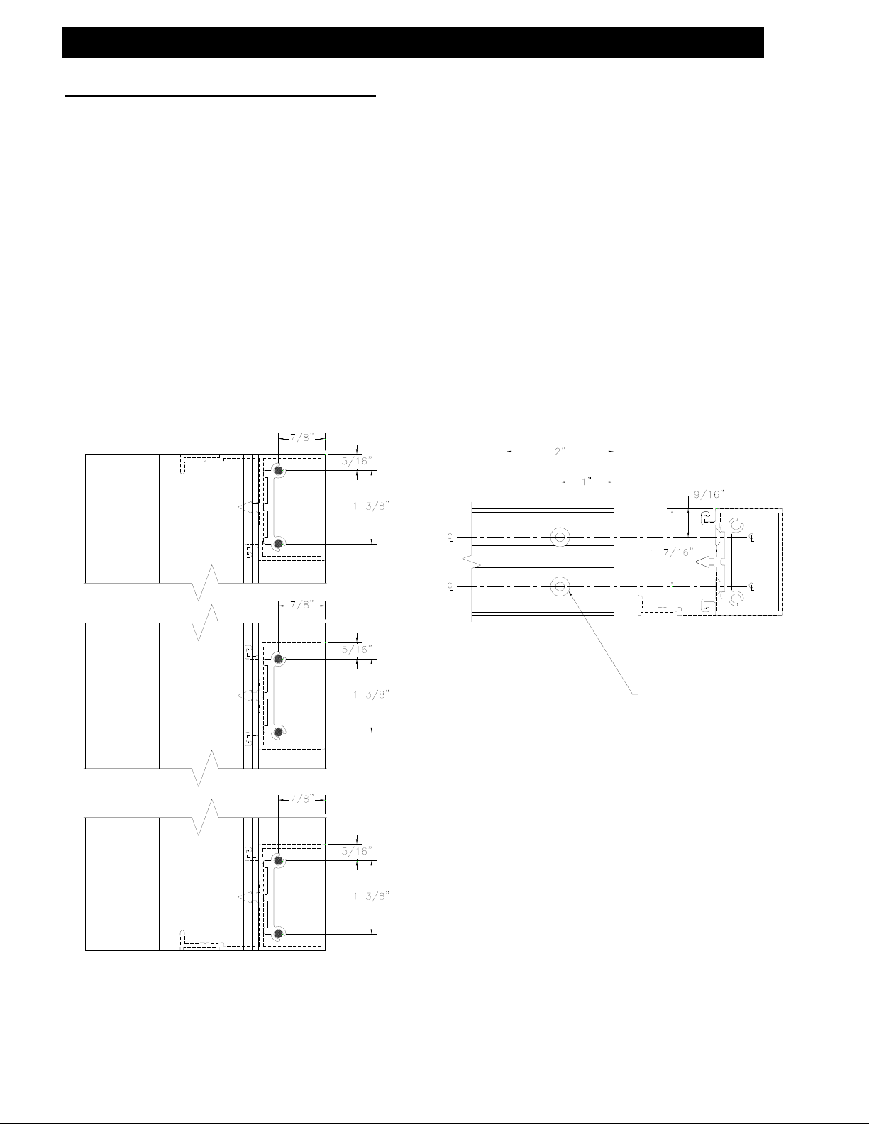
Step 8) Heavy-Duty Anchor Installation
OUTSIDE SET GLASS
21/64"
7/8"
7/16"
K473
Install required vertical mullion
anchors as shown in Figures 14
through 18. Anchors should be
installed on the vertical mullions and
anchored thru the subsill after the
frame unit is installed in the
opening. HD anchors will not work
with 8349 or 8357 mullions.
SUBSILL
2S44
[FIG. 14]
23/64"
CENTER-SET GLASS
27/64"
27/64"
K473
3/16"
K992
K992
5/16"
[FIG. 15]
OFFSET MULLIONS CENTER-SET MULLIONS
1 1/8" ± 1/16" 1 1/8" ± 1/16"
K473
1 5/16"
29/64"
SUBSILL
2S44
3 5/16"
NOTE: K992 COMES WITH TWO ANGLE
BRACKETS AND TWO FASTENERS. K473
COMES WITH ONE ANGLE BRACKET AND
[FIG. 16] [FIG. 18]
1 1/8" ± 1/16"
hese recommendations are for general erection procedures only. For actual job
conditions, see the details on the shop drawings. For perimeter anchor type and
s
acing, refer to the approved shop drawings or consult the project design professional.
Do not use 4471 Subsill
with heavy duty anchors.
INSIDE SET GLASS
51/64"
SUBSILL
2S44
TWO FASTENERS.
K992
[FIG. 17]
7/8"
3 5/8"
June 2012 PART NO. Y017 Page 55 of 90
Page 56

Series 433 Triple Set Installation Instructions
SECTION VI: Subsill Fabrication and Installation
(Includes Offset and Center-Set Glazing)
Step 9) Subsill Anchor Seal
The subsill anchors must be sealed with a silicone type sealant. To ensure a good seal,
tool the sealant onto the fastener and surrounding metal. If HD anchors are used,
ensure that the anchor angle and fasteners are sealed also. This procedure should be
followed immediately after anchor installation so it is not forgotten.
Step 10) Subsill Perimeter Seal
The subsill interior should be sealed with a silicone type seala nt. Apply sealant and tool
the sealant to ensure a good seal. Clean off all excess sealant. At this time, use a
silicone type sealant to seal the thermal break area as shown in Figure 20. Tool the
sealants into the thermal break area, and ensure that sealant is smooth and flat with
the subsill surface. This procedure should be done prior to installation of the framing
system so it is not forgotten.
[FIG. 19]
SILICONE
TYPE
SEALANT
SILICONE TYPE SEALANT
[FIG. 20]
SUBSILL
2S44
SUBSILL
SUBSILL
2S44
SILICONE
TYPE
SEALANT
4471
SUBSILL
4471
SILICONE
TYPE
SEALANT
SILICONE
TYPE
SEALANT
June 2012 PART NO. Y017 Page 56 of 90
Page 57

Series 433 Triple Set Installation Instructions
SECTION VI: Subsill Fabrication and Installation
(Includes Offset and Center-Set Glazing)
Step 11) Subsill Splicing
Verify that the subsill has been installed according to the instructions on pages 45
through 52. Splice areas are to be centered at a vertical mullion only. Maximum subsill
length between splices is 20’ to 25’. If a splice is required, leave a 1/4" gap between
the subsill ends at the splice area. Install and anchor the next run of subsill. Use a
silicone type sealant and a strip of WM01, bond breaker tape 1 7/8", wide and
approximately 7 1/2" long to create the splice material. Apply silicone to both sides of
the subsill ends and fill the void between the subsills as shown in Figure 21. Ensure
that the bond breaker tape is centered over the 1/4" gap, and set the bond breaker
tape into the sealant. Tool the silicone over the bond breaker tape to create a
watertight seal. If more sealant is required to cover the bond breaker tape, apply the
required amount. Ensure that the splice joint does not interfere with the anchor legs of
the sill and subsill. Making sure that the splice joint is located at the center of the
vertical mullions does this. Refer to the shop drawings or architectural drawings for
mullion centerlines.
APPLY SILICONE TYPE SEALANT TO
CREATE A THIN BED TO SET THE
BOND BREAKER TAPE INTO.
[FIG. 21]
SUBSILL
2S44
FILL VOID BETWEEN
SUBSILLS WITH A SILICONE
TYPE SEALANT FROM THE
INTERIOR LEG TO THE BACK
OF THE EXTERIOR LEG.
AFTER INSTALLING THE BOND
BREAKER TAPE, TOOL THE
SEALANT OVER THE EDGE OF
THE TAPE TO PRODUCE A
WATERTIGHT SEAL.
AFTER THE SPLICE IS INSTALLED, APPLY A
COSMETIC SEAL TO THE INTERIOR GAP,
VERTICALLY UP THE SUBSILL SPLICE.
2S44 Shown
SUBSILL
4471 Similar
2S44
June 2012 PART NO. Y017 Page 57 of 90
Page 58

Series 433 Triple Set Installation Instructions
SECTION VI: Subsill Fabrication and Installation
(Includes Offset and Center-Set Glazing)
Step 12) Subsill Corner Miter and Splicing
When mitering the subsill for corner applications, cut the subsill material at the
appropriate angle required to form the correct corner. Install the subsill by follow ing
the previous subsill installation instructions. Once the subsill is installed and a tight
miter joint is achieved, use the instructions on page 53 for creating a splice joint seal.
Follow the instructions for sealing a standard splice joint except there should be no gap
between the ends of the mitered subsills. Ensure that the bond breaker tape and
sealant used to create the seal are smooth, so they do not interfere with the anchor
legs on the sill and subsill. If a 90° SSG mullion is used, the bond breaker tape should
be 1-1/2" wide because the corner mullion is 1-3/4" wide.
2S44 Shown
SUBSILL
4471 Similar
2S44
[FIG. 22]
June 2012 PART NO. Y017 Page 58 of 90
Page 59

Series 433 Triple Set Installation Instructions
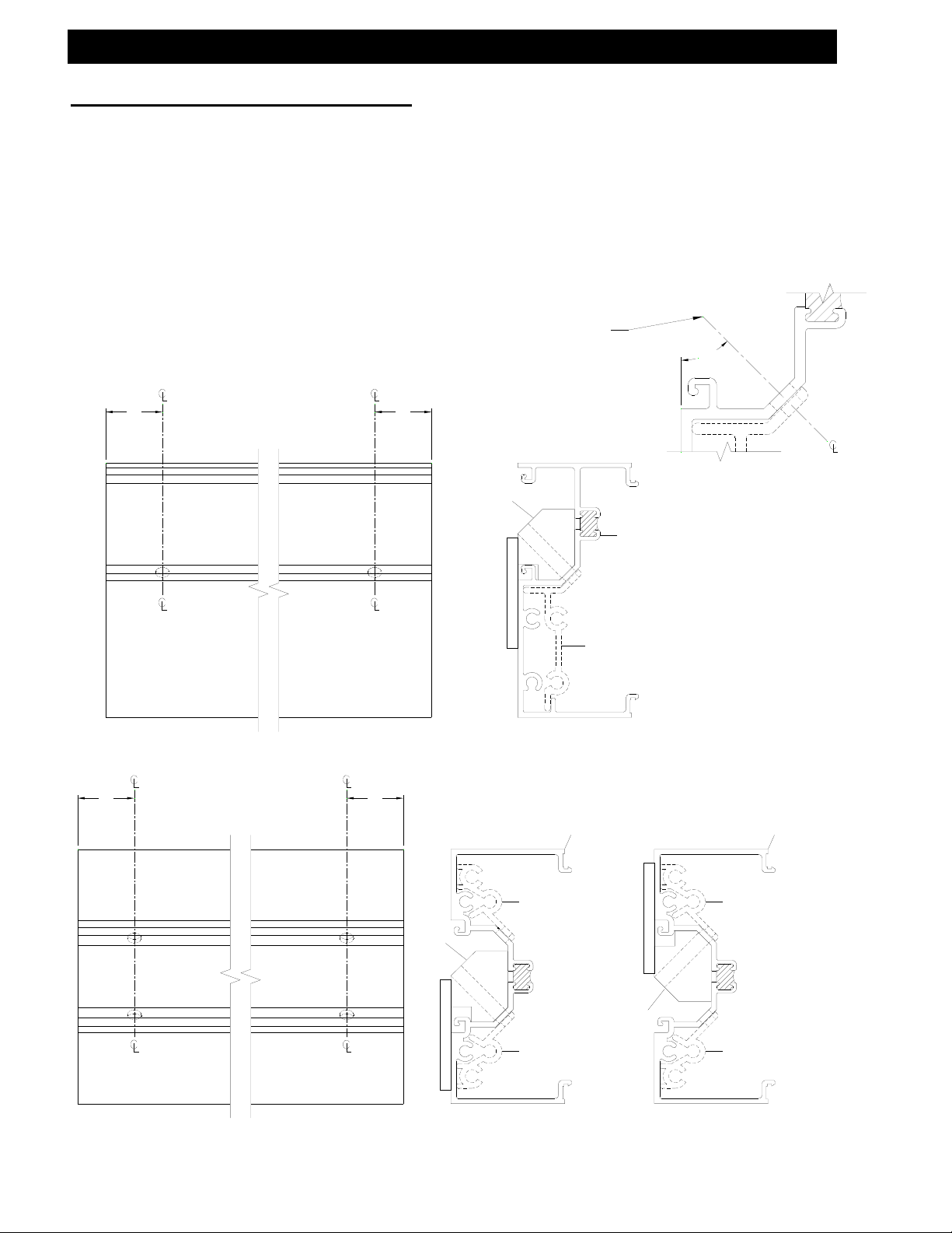
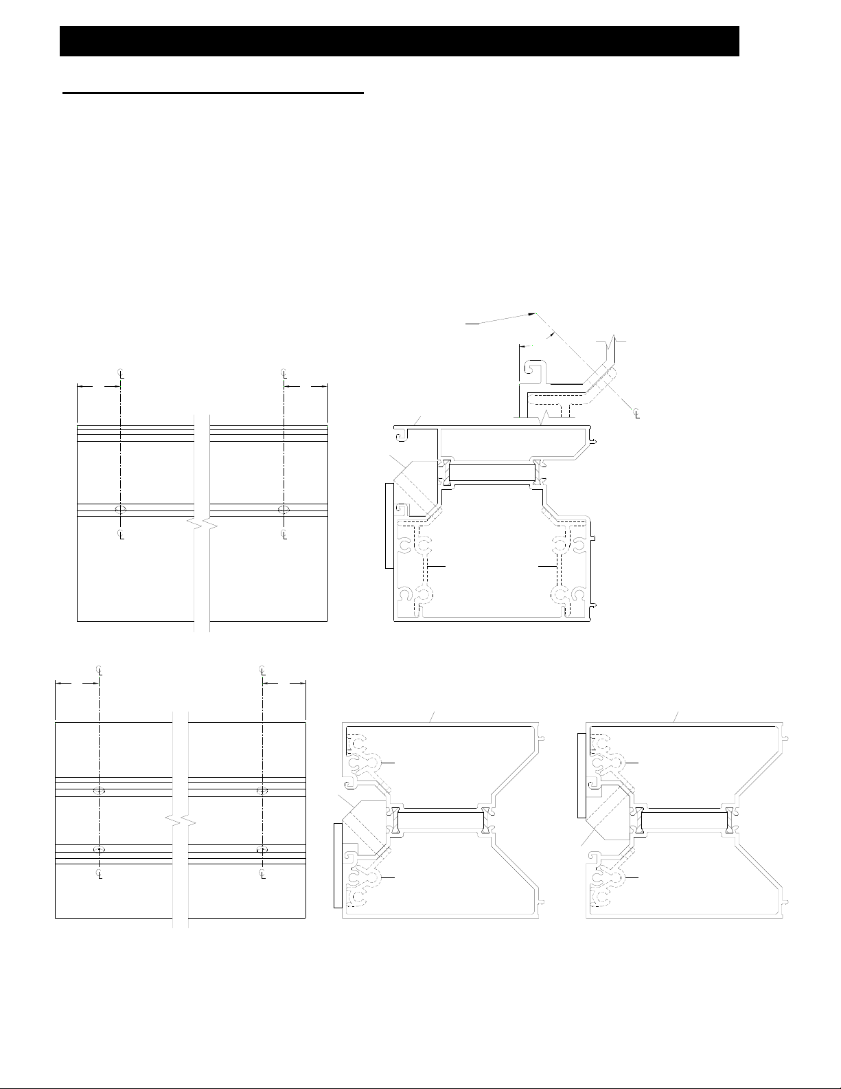
SECTION VII: Corners
(Includes Offset and Center-Set Glazing)
Corner Identification and Assembly
Proper identification of the required corner members is necessary to ensure a timely
installation process. See details of each corner variation on pages 55 through 57 in
Figures 23 through 33.
23) 90° outside set corner 27) 135° outside set corner
24) 90° inside set corner 28) 135° inside set corner
25) 90° center-set corner 29) 135° center-set corner
26) 90° multiple glass plane corner 30) 135° multiple glass plane corner
31) 90° outside set SSG corner
Both inside and outside corners can be accommodated with these details.
Figures 32 and 33 on page 61 show typical inside corners.
Determine that the subsill has been installed according to the instructions lis ted on
pages 46-51. Ensure the adjacent ladders are built with the appropriat e mullion half to
be used with the corner mullion. Install the corner member into the subsill. It may be
necessary to temporarily brace the vertical corner member until the adjacent ladders
are installed and anchored. Install and snap one corner ladder completely, and then
install and snap the other onto the corner mullion.
If door openings are required on a run that incorporates a corner member, begin at the
doorframe and assemble towards the corner area with the required ladders.
Unassembled corner extrusions must be attached to the ladders, and the corner
member must be assembled after installation of both adjacent ladders.
[FIG. 23] [FIG. 24]
June 2012 PART NO. Y017 Page 59 of 90
Page 60

Series 433 Triple Set Installation Instructions
SECTION VII: Corners
(Includes Offset and Center-Set Glazing)
[FIG. 25]
[FIG. 27]
NOTE: Figure 26 shows Inside and Outside
set verticals. You can create a multi-plane
configuration by using any of the vertical
mullions shown in figures 23, 24 and 25.
NOTE: Figure 26 can be
accommodated by using vertical
mullions from Figures 23, 24, and 25
in any combination.
[FIG. 26]
[FIG. 28]
June 2012 PART NO. Y017 Page 60 of 90
Page 61

Series 433 Triple Set Installation Instructions
SECTION VII: Corners
(Includes Offset and Center-Set Glazing)
[FIG. 29] [FIG. 30]
[FIG. 32] [FIG. 33]
[FIG. 31]
NOTE: Figure 30 can be
NOTE: Figure 30 shows Inside
accommodated by using vertical
and Outside set verticals. You
mullions from Figures 27, 28, and 29
in any combination.
can create a multi-plane
configuration by using any of
the vertical mullions shown in
figures 27, 28 and 29.
NOTE: Figures 32 and 33 show the typical use
of corner mullions as inside corners. All glass
planes can be accommodated in both inside
and outside corners.
June 2012 PART NO. Y017 Page 61 of 90
Page 62

Series 433 Triple Set Installation Instructions
SECTION VIII: Installation
(Includes Offset and Center-Set Glazing)
Step 1) Sealing the Sill onto the Subsill
Apply a silicone type sealant to the subsill in the location shown in Figure 34 before
installing the first ladder. Make sure that enough se alant is applied to seal the areas
shown in Figure 35. After installing the ladder and anchoring it, clean off all excess
sealant from exposed areas. Do not allow sealant to cure before placing the system
frames. It will interfere with the sill to subsill engagement.
SEALANT
2S44 SHOWN
4471 SIMILAR
[FIG. 34]
8362 SHOWN
8375 SIMILAR
SEALANT
2S44 SHOWN
4471 SIMILAR
[FIG. 35]
June 2012 PART NO. Y017 Page 62 of 90
Page 63

Series 433 Triple Set Installation Instructions
SECTION VIII: Installation
(Includes Offset and Center-Set Glazing)
Step 2) Installing Jamb Side Ladder
Place the ladder on the subsill at an approximate 30° angle. While applying pressure
upward, rotate the ladder into the condition. See Figure 35 on page 58 for sill
placement into the subsill. When rotated correctly, the exterior face of the sill should
be flush with the exterior face of the subsill.
CONDITION
LADDER
[FIG. 36]
CONDITION
2S44
SUBSILL
LADDER
[FIG. 37]
June 2012 PART NO. Y017 Page 63 of 90
Page 64

Series 433 Triple Set Installation Instructions
SECTION VIII: Installation
(Includes Offset and Center-Set Glazing)
Step 3) Anchoring the Head
For D.L.O.s 36" and narrower, the anchors must be spaced 6" from the jamb or
vertical members. For D.L.O.s 36" and wider, the outside anchors must be spaced 6"
from the jamb with the center anchor centered on the D.L.O. See Figure 38 below.
These recommendations are for general erection procedures only. For actual
job conditions, see the details on the shop drawings. For perimeter anchor
type and spacing, refer to the approved shop drawings or consult the project
design professional.
June 2012 PART NO. Y017 Page 64 of 90
6" "VARIES"
FD
LESS THAN OR EQUAL 36"
8363 SHOWN
8393 SIMILAR
1 1/8"
REF.
1 3/16"
REF.
EQUAL
6"
FD
6"
FD
GREATER THAN 36"
FD
EQUAL
6"
FD
[FIG. 38]
8372
2 11/16" REF.
8366
3 5/16" REF.
4G29
3G46
2 11/16" REF.
Page 65

gn p
Series 433 Triple Set Installation Instructions
SECTION VIII: Installation
(Includes Offset and Center-Set Glazing)
Step 4) Anchoring the Jambs
Anchors must be spaced 6" from the sill or head, and 24" O.C. ± 4", so they do not
interfere with the horizontal members. See Figure 42. Regardless of glass pocket
configuration, the anchors should be placed so they do not fasten through the thermal
area. See Figures 43 through 46.
These recommendations are for general erection procedures only. For actual
job conditions, see the details on the shop drawings. For perimeter anchor
type and spacing, refer to the approved shop drawings or consult the project
desi
24" ± 4"
24" ± 4"
24" ± 4"
rofessional.
6"
6"
[FIG. 42]
8439 SYM.
8349
[FIG. 43]
8356
[FIG. 45]
1 7/16"
REF
8359
1 7/8"
REF
8359
[FIG. 44]
8361
LB90
[FIG. 46]
8356
1 7/16"
REF
2"
REF
June 2012 PART NO. Y017 Page 65 of 90
Page 66

Series 433 Triple Set Installation Instructions
SECTION VIII: Installation
(Includes Offset and Center-Set Glazing)
Step 5) Sealing Vertical Mullions
Prior to installing an intermediate vertical mullion or perimeter jamb, apply silicone type
sealant to the vertical mullion in the location shown in Figure 47 below at the Interior
joints only. Apply sealant where indicated 6-8 inch es up from the bottom of the vertical
joints. Apply enough sealant so when the filler or opposite mullion half is snapped, it
will create a good seal. Wipe off excess sealant from the exposed Interior of the frame.
This sealant practice should be followed for all variations of vertical mullions including
corners and perimeter jambs, except where a perimeter mullion uses vinyl filler. See
Figures 48 through 54.
SEAL
[FIG. 47]
8352
[FIG. 48] [FIG. 49] [FIG. 50]
SEAL
8353
SEAL
8360
SNAP
EXCESS
CLEAN
SEAL
8358
8361
8355
June 2012 PART NO. Y017 Page 66 of 90
Page 67

Series 433 Triple Set Installation Instructions
SECTION VIII: Installation
(Includes Offset and Center-Set Glazing)
SEAL
8356
[FIG. 53]
8354
8359
8356
[FIG. 51]
SEAL
[FIG. 52]
8356 SHOWN IN CORNER
MULLIONS, OTHERS SIMILAR.
8380
Seal Vertical 6”-8” from the bottom up.
8356
8356
8354
SEAL
8381
[FIG. 54]
SEAL
8356
June 2012 PART NO. Y017 Page 67 of 90
Page 68

R
R
R
Series 433 Triple Set Installation Instructions
SECTION VIII: Installation
(Includes Offset and Center-Set Glazing)
Step 6) Installing the Second Ladder
Make sure that the anchors are installed into the head and jamb of the first ladder.
Apply the sealant as specified in Figures 47 through 54 on pages 66 and 67. Apply
sealant to the subsill as shown on page 40. Place the second ladder on the subsill at an
approximate 30° angle. Rotate the ladder into the condition approximately 1/4" away
from the previously installed ladder.
[FIG. 55]
8359 SHOWN
OTHERS SIMILAR
[FIG. 56]
8356 SHOWN
OTHERS SIMILA
CONDITION
SECOND
LADDE
CONDITION
[FIG. 57]
SECOND
LADDE
June 2012 PART NO. Y017 Page 68 of 90
Page 69

R
R
Series 433 Triple Set Installation Instructions
SECTION VIII: Installation
(Includes Offset and Center-Set Glazing)
Step 7) Snapping Vertical Mullions Together
To snap vertical mullions together, line up the mullion halves once the 1/4" gap is
achieved between the mullion halves. See Figure 56 on page 64. Place one clamp at
the bottom of the mullions using wood blocks to protect the extrusions. Tighten the
clamp until the mullion halves begin to snap together. Place another set of wood
blocks and a clamp at the middle of the mullions and tighten it. Then repeat the same
process on the top. Tighten the clamps until the mullion halves are pressed together.
The sight line should be 2". It may be necessary to work from one clamp to the next
several times, or move the clamps, to ensure the mullions are snapped together evenly.
See Figure 59. DO NOT try to hammer the mullion halves together! This will dent,
bend, scratch, or deform the mullions and may cause them to leak. Ensure that the
previous ladder is anchored using the requirements on page 60 before installing the
2nd ladder.
[FIG. 58]
C-CLAMP
OR SIMILA
WOOD BLOCK
8358/8355 SHOWN,
OTHERS SIMILA
8358
8355
2" REF.
[FIG. 59]
June 2012 PART NO. Y017 Page 69 of 90
Page 70

Series 433 Triple Set Installation Instructions
SECTION VIII: Installation
(Includes Offset and Center-Set Glazing)
Step 8) Snapping the Expansion Mullion (Offset Mullion)
To snap the expansion mullion together, line up the mullion halves and gaskets. See
Figure 60. Place one clamp at the bottom of the expansion mullion using wood blocks
to protect the extrusions. Tighten the C-clamp until the expansion mullion halves begin
to snap together. Place another set of wood blocks and a C-clamp at the middle of the
expansion mullion and tighten it. Then repeat the same process on the top. Tighten
the C-clamps until the sight line becomes 2 1/4". It may be necessary to work from one
clamp to the next several times, or move the clamps to ensure the mullions are
snapped together evenly. See Figure 61. DO NOT try to hammer the expansion
mullion together! This will dent, bend, scratch, or deform the expansion mullion and
may cause it to leak. Anchor the head using the requirements shown on page 64
before installing the next ladder. If this is the last ladder, anchor the jambs as required
on page 65 and proceed to the perimeter sealing process, Step 11 on page 72.
C-CLAMP
OR SIMILAR
8394
8395
WOOD BLOCK
8394
8395
2.250"
[FIG. 60]
[FIG. 61]
June 2012 PART NO. Y017 Page 70 of 90
Page 71

Series 433 Triple Set Installation Instructions
SECTION VIII: Installation
(Includes Offset and Center-Set Glazing)
Step 9) Snapping the Expansion Mullion (Center-Set Mullion)
To snap the expansion mullion together, line up the mullion halves and gaskets. See
Figure 62. Place one clamp at the bottom of the expansion mullion using wood blocks
to protect the extrusions. Tighten the C-clamp until the expansion mullion halves begin
to snap together. Place another set of wood blocks and a C-clamp at the middle of the
expansion mullion and tighten it. Then repeat the same process on the top. Tighten
the C-clamps until the sight line becomes 2". It may be necessary to work from one
clamp to the next several times, or move the clamps, to ensure the mullions are
snapped together evenly. See Figure 63. DO NOT try to hammer the expansion
mullion together! This will dent, bend, scratch, or deform the expansion mullion and
may cause it to leak. Anchor the head using the requirements shown on page 64
before installing the next ladder. If this is the last ladder, anchor the jambs as required
on page 65 and proceed to the perimeter sealing process, Step 11 on page 72.
8396
[FIG. 62]
8397
WOOD BLOCK
C-CLAMP
OR SIMILAR
8396
[FIG. 63]
8397
2.000"
June 2012 PART NO. Y017 Page 71 of 90
Page 72

Series 433 Triple Set Installation Instructions
SECTION VIII: Installation
(Includes Offset and Center-Set Glazing)
Step 10) Anchoring the Second Ladder
After the mullion halves are snapped correctly, ensure that the mullions are plumb and
true and anchor the head as shown in Figure 38 on page 64. If this is the last ladder in
a run, ensure that the mullion halves are snapped correctly and install the required
shims between the jamb and condition. Install the head and jamb anchors. Ensure
that the jamb anchors do not separate the last ladder from the previous. It may be
necessary to shim tightly against the condition to prevent this.
Step 11) Perimeter Seal
When the unit is installed and anchored, begin placing caulk rope into the gap between
the perimeter and the frame. Apply a generous amount of silicone type sealant to the
gap between the frame and rough opening. Tool off all excess sealant to ensure a
good seal and to achieve an appropriate appearance. See Figures 64 through 68
below.
4 ½” HEADS
SIMILAR
8366
LB77
LB77
8372
8363 SHOWN
8393 SIMILAR
[FIG. 65]
[FIG. 66]
[FIG. 64]
[FIG. 67] [FIG. 68]
8356
8359
LB90
8359 SYM.
8361
June 2012 PART NO. Y017 Page 72 of 90
Page 73

Series 433 Triple Set Installation Instructions
SECTION IX: Glazing
(Includes Offset and Center-Set Glazing)
IDENTIFICATION OF GLASS POCKETS AND SETTING BLOCKS
INSIDE GLAZED HORIZONTALS
HN92
INSIDE GLAZED SILLS
[FIG. 69]
8363
8365
[FIG. 70]
8366
8364
[FIG. 71]
8372
Customer / Installer Note:
EFCO setting blocks are typically 4" in length with
different depths. If the glazing infill is "NOT BY EFCO"
and glazing sizes are larger than 40 square feet, then
the glazing details must be reviewed by the glazing
manufacturer for proper setting block size.
8367
HN92
8368
HN92
HN32
[FIG. 73]
[FIG. 74]
8375
[FIG. 72]
8362
HN32
8362
HN32
4 ½” SILLS &
HORIZONTALS
SIMILAR
June 2012 PART NO. Y017 Page 73 of 90
Page 74

Series 433 Triple Set Installation Instructions
SECTION IX: Glazing
(Includes Offset and Center-Set Glazing)
IDENTIFICATION OF GLASS POCKETS AND SETTING BLOCKS
OUTSIDE GLAZED HORIZONTALS
[FIG. 75]
8363
8365
HN92
[FIG. 76]
8367
8364
HN92
[FIG. 77]
8368
HN92
[FIG. 78] [FIG. 82]
8386
8365
Customer / Installer Note:
EFCO setting blocks are typically 4" in length with
different depths. If the glazing infill is "NOT BY EFCO"
and glazing sizes are larger than 40 square feet, then
the glazing details must be reviewed by the glazing
manufacturer for proper setting block size.
HN92
8366
8372
8385
8382
OUTSIDE GLAZED SILLS
[FIG. 79]
8362
HN32
HN32
HN32
[FIG. 80]
8362
[FIG. 81]
8384
4 ½” SILLS &
HORIZONTALS
SIMILAR
HN32
8375
June 2012 PART NO. Y017 Page 74 of 90
Page 75

Series 433 Triple Set Installation Instructions
SECTION IX: Glazing
(Includes Offset and Center-Set Glazing)
Step 1) Identification of Glass Pockets
INSIDE AND OUTSIDE GLAZED VERTICALS
Ensure that each vertical DLO has at least one DEEP glass pocket on either side. It is
necessary for the glazing installation that a deep pocket be used to load the glazing
units. These details are shown with the deep glazing pockets shown right justified for
viewing clarity.
[FIG. 83]
[FIG. 88] [FIG. 89] [FIG. 90]
[FIG. 84]
[FIG. 85] [FIG. 86]
DEEP
SHALLOW
[FIG. 87]
8352
8349
8353
8354
8354
8439
8359
DEEP
SHALLOW
DEEP DEEP
SHALLOW
DEEP
8356
DEEP
8357
8361
8355
8358
[FIG. 91] [FIG. 92]
8396
8397
8394
8360
DEEP DEEP DEEP DEEP DEEP
SHALLOW SHALLOW SHALLOW SHALLOW SHALLOW
8395
June 2012 PART NO. Y017 Page 75 of 90
Page 76

g
Series 433 Triple Set Installation Instructions
SECTION IX: Glazing
(Includes Offset and Center-Set Glazing)
Step 2) Glass Size Formulas
For captured glazing variations, the glass size formula is DLO + 7/8". For structural
glaze systems the glass size formula is DLO + 1 1/2”. The glass size formula from
captured mullion to SSG mullion is DLO + 1 3/16". From SSG mullion to SSG mullion
the glass size formula is DLO + 1 1/2". Captured mullions have a glass bite of 7/16".
SSG mullions have a glass bite of 3/4". 90° SSG corners use offset glass with the
interior glass size and the exterior glass size being different (see Figure 94). Refer to
Figures 93, 94, and 95 below.
Note that the 90° SSG mullions
have glass that utilizes dual
width glazing. Glass sizes
should be specified using the
interior & exterior glass
formulas shown in Fi
7/16"
D.L.O.
7/16"
VERTICAL GLASS SIZE DOES NOT CHANGE WHEN SSG MULLIONS ARE USED.
GLASS
GLASS
GLASS
7/16"
7/16"
D.L.O.
GLASS SIZE
D.L.O. + 7/8"
7/16"
D.L.O.
7/16"
GLASS SIZE
D.L.O. + 7/8"
7/16"
D.L.O.
7/16"
GLASS SIZE
D.L.O. + 7/8"
4 ½” SILLS &
HORIZONTALS
SIMILAR
ure 94.
Customer / Installer Note:
EFCO setting blocks are typically 4" in length with
different depths. If the glazing infill is "NOT BY EFCO"
and glazing sizes are larger than 40 square feet, then
the glazing details must be reviewed by the glazing
manufacturer for proper setting block size.
[FIG. 95]
GLASS
GLASS
SIZE
D.L.O. + 7/8"
GLASS
SIZE
D.L.O. + 7/8"
D.L.O.
GLASS
[FIG. 93]
GLASS GLASS
3/4"
D.L.O.
7/16"
GLASS SIZE
D.L.O. + 1 3/16"
7/16"
D.L.O.
7/16"
3/4"
INT. GLASS SIZE
D.L.O. + 1 3/4"
EXT. GLASS SIZE
7/16"
3/4"
D.L.O. + 1 1/2"
D.L.O.
D.L.O. + 2 1/2"
7/16"
D.L.O.
3/4"
D.L.O.
GLASS SIZE
[FIG. 94]
1"
3/4"
GLASS
GLASS
SIZE
D.L.O. + 7/8"
June 2012 PART NO. Y017 Page 76 of 90
Page 77

g
Series 433 Triple Set Installation Instructions
SECTION IX: Glazing
(Includes Offset and Center-Set Glazing)
Step 3) Installing the Water Deflector
HWD1 - WATER DEFLECTOR
The HWD1 water deflector is designed to be universal. It may
need to be modified to fit certain glazing pockets. Install the
HWD1 at the ends of the intermediate horizontals only. It is
not required at heads or sills. Use a silicone type sealant to
adhere the HWD1 onto the intermediate horizontal. Ensure
that the HWD1 fits flush with the top of the intermediate
horizontal glazing pocket and smooth any excess silicone
sealant so water will flow easily over the water deflector.
Step 3A) Installing the Water Diverter
FW33 - WATER DIVERTER
Install the FW33 at the intermediate horizontals
only. It is not required at heads or sills. Use a
silicone type sealant to adhere the FW33 onto
the intermediate horizontal. Ensure that the
FW33 fits flush with the top of the intermediate
horizontal glazing pocket and smooth any
excess silicone sealant as shown in Figure 97
so water will flow easily over the water
deflector.
Step 3B) Installing SSG Horiz. Mullion
Brid
K895 – SSG BRIDGE ASSEMBLY
Install K895 at the intermediate
horizontals only. It is not required at
heads or sills. Use a silicone type sealant
to adhere the K895 onto the intermediate
horizontal. Ensure that the K895 fits flat
on top of the intermediate horizontal
glazing pocket and smooth any excess
silicone sealant as shown in Figure 99 so
water will flow easily over the water
deflector.
e Assembly
across the horizontal mullions
Press the water diverter into the
sealant and apply a bead of
sealant to the perimeter seam.
vertical to achieve a watertight
[FIG. 96]
This end extends into the vertical
glazing pocket and over the
lower glass unit's corner.
Apply silicone type sealant
before installing the FW33.
Tool into the horizontal and
seal at the diverter.
Tool sealant smooth
and flat, as not to
interfere with glazing.
TYP. VERTICAL
HWD1
TYP. HORIZONTAL
GLASS UNIT BELOW
[FIG. 97]
FW33
[FIG. 98]
June 2012 PART NO. Y017 Page 77 of 90
Page 78

Series 433 Triple Set Installation Instructions
SECTION IX: Glazing
(Includes Offset and Center-Set Glazing)
Step 4) Installing Glass Blocks
Glass blocks for the 433 system are designed to be used at 1/4 points and 1/8 points
for special dead load applications. For intermediate horizontals, use glass block HN92.
For sills, use glass block HN32. It may be necessary to use a small amount of sealant
on the bottom of the glass blocks to ensure they remain in the intended position. Refer
to Figure 100 below for 1/4 point and 1/8 point verification.
TYP. HORIZ.
[FIG. 98]
[FIG. 99]
OUTSIDE SET, INSIDE GLAZED
SHOWN. OTHERS ARE SIMILAR
[FIG. 99]
[FIG. 100]
D.L.O. / 4 D.L.O. / 8
D.L.O. / 4
1/4 POINT
BLOCKING
D.L.O. / 8
1/8 POINT
BLOCKING
HN32HN92
TYP. SILL
4 ½” SILLS &
HORIZONTALS
SIMILAR
June 2012 PART NO. Y017 Page 78 of 90
Page 79

g
Series 433 Triple Set Installation Instructions
SECTION IX: Glazing
(Includes Offset and Center-Set Glazing)
Step 5) Installation of Glazing Gasket
For inside glazed applications, install the exterior gasket prior to glass installation. For
outside glazed applications, install the interior gasket prior to glass installa tion.
NOTE: To install glazing gasket, start by pushing the gasket in place at the ends.
Move to the middle, then to quarter points and work the "waves" toward the ends. Do
not stretch the gasket or it will return to its original form, creating gaps at the gasket
intersection. (Gasket length=D.L.O. dim X 1.005. or D.L.O. dim + 1/2%)
See Fi
SIZE THE GASKET LENGTH BY USING THE FOLLOWING FORMULA.
D.L.O. DIM X 1.005 (D.L.O. DIM. + 1/2%)
ure 101 below.
[FIG. 101]
HEAD
8" - 12"
VARIES
JAMB GASKET
RUNS THRU
INSTALL FIRST
VERT. GASKET
RUNS THRU
INSTALL FIRST
SILL
JAMB
VERTICAL
TYPICAL
SEALANT
SEAL 1" VERTICALLY AND HORIZONTALLY IN THE
GASKET RACES WITH SILICONE TYPE SEALANT AT
ALL CORNERS. SEAL THE ENDS OF HORIZONTAL
GASKETS. CLEAN OFF ANY EXCESS SEALANT.
SEALING RACES AND GASKET ENDS IS REQUIRED AT
THE INTERIOR OF THE SYSTEM. EXTERIOR SEALANT
AT RACE AND GASKET IS OPTIONAL.
June 2012 PART NO. Y017 Page 79 of 90
Page 80

Series 433 Triple Set Installation Instructions
SECTION IX: Glazing
(Includes Offset and Center-Set Glazing)
Step 6) Glass Installation
A) Make sure the glazing blocks are still in place in the D.L.O. as instructed in Figures
98 and 99.
- For the following steps use Figures 102 and 103 below.
B) Position the glass on the appropriate side of the framing without the removable
glass stop installed. Shift the glass into the deep pocket to begin glass installation.
C) Swing the opposite edge of the glass around to align with the glazing pocket.
D) Slide the glass into the shallow pocket and lower onto the setting blocks. Shift the
glass until there is equal glass bite on both edges of the D.L.O. Ensure that the
preinstalled gasket does not roll out of the gasket race when moving the glass unit into
place.
E) Snap on the removable glass stop and install the antiwalk blocks and glazing gasket.
Use the instructions on page 79 for gasket installation. See Figures 114 through 119 on
pages 86, 87 and 88 for installation of the snap-in glass stop and antiwalk blocks.
NOTE:
This procedure works for all
captured glazing configurations
whether it is outside set
(shown), inside set, or
center-set glazing and inside
(shown) or outside glazed.
[FIG. 101]
[FIG. 102]
C
B
GLASS
D
D
GLASS
E
B
[FIG. 103]
[FIG. 102]
June 2012 PART NO. Y017 Page 80 of 90
Page 81

Series 433 Triple Set Installation Instructions
SECTION IX: Glazing
(Includes Captured and Structural Glazed Mullion Systems)
Step 7) Glass Installation
Structural Glazed Head and Sill Through
A) Make sure the glazing blocks are still in place in the D.L.O. as instructed in Figures
98 and 99.
- For the following steps use Figures 104 through 106 below.
B) Prior to glass install, place WM80 tape into position on SSG mullion.
C) Position the glass on the appropriate side of the framing without the removable
glass stop installed. Shift the glass out past the structural glaze mullion and into the
deep pocket to begin glass installation, ensure the glass does not wipe the WM80 tape
out of position.
D) Swing the opposite edge of the glass around to align with the glazing pocke t.
E) Slide the glass until there is the correct glass bite shown on both D.L.O. edges.
(7/16" @ captured vertical and 3/4" at SSG vertical.)
F) Snap on the removable glass stop and install the antiwalk blocks and glazing gasket.
Use the instructions on page 79 for gasket installation. See Figures 114 through 119 on
pages 86, 87 and 88 for installation of the snap-in glass stop and antiwalk blocks.
GLAZING GASKET
C
TEMPORARY
PIECES OF
D
B
[FIG. 104]
[FIG. 105]
D
E
B
[FIG. 106]
June 2012 PART NO. Y017 Page 81 of 90
Page 82

Series 433 Triple Set Installation Instructions
SECTION IX: Glazing
(Includes Captured and Structural Glazed Mullion Systems)
Step 8) Glass Installation
Structural Glazed Vertical Through
- For the following steps use Figures 107 through 109.
A) Make sure the setting blocks are placed at 1/4 points in each D.L .O. or as required
on the architectural drawings. See Figure 99 on page 78.
B) Prior to glass install, place WM80 tape into position on SSG mullion.
C) Position the glass at the exterior of the framing with the head and sill face covers
removed. Lift the glass into the frame and onto the setting blocks; ensure the glass
does not wipe the WM80 tape out of position.
D) Shift the glass into the pocket in the perimeter jamb until there is the correct glass
bite on both edges of the D.L.O. (7/16" captured vertical or 3/4" SSG vertical).
E) Install the appropriate covers. Place temporary pieces of the glazing gasket along
the head, perimeter jamb, and sill. Place the temporary glazing clips in the structural
mullion race, and rotate to hold glass at the structural mullion. See Figure 108. Install
all glazing gaskets. See Figure 101 on page 79. Install the next lite before filling the
structural glazing gap. See Figure 110 on page 83.
TEMPORARY GLAZING
D
CLIPS (HGR1)
TEMPORARY
PIECES OF
GLAZING GASKET
[FIG. 106]
C
D
B
D
A
[FIG. 107]
[FIG. 108]
June 2012 PART NO. Y017 Page 82 of 90
Page 83

Series 433 Triple Set Installation Instructions
SECTION IX: Glazing
(Includes Captured and Structural Glazed Mullion Systems)
Filling the Structural Glazing Gap
-This procedure applies to the 2-piece structural glazed vertical, the head & sill thru
After the interior sealant has cured, typically an overnight setup is required, mask off the
glass edges with masking tape to minimize cleanup and provide a professional appearance.
Then remove the temporary glazing clips and proceed with filling the void between the
glass units at the exterior with backer rod and structural silicone sealant for a weather tight
seal. At the horizontal members, fill the cavity with sealant to fill the void out to the gasket.
See Figure 110. Tool the sealant using a putty knife across the glass edges. Remove
excess silicone from the glass surface by removing the masking tape before a skin begins to
form. Any excess sealant on the glass units can be removed with a razor blade.
1" GLASS
Note:
The success of structural silicone glazed projects has been the result of compatibility tests
performed on actual materials supplied to the project. The installer must make sure that successful
compatibility tests are performed in accordance with the silicone manufacturer's recommendations
and procedures.
structural glazed vertical, & the 90 degree structural glaze corner-
S.S.G. VERTICAL
HEAD & SILL THRU
S.S.G. VERTICAL
VERTICAL THRU
S.S.G. 90° CORNER
STRUCTURAL
SILICONE
1" GLASS 1" GLASS 1" GLASS
1" GLASS
STRUCTURAL
SILICONE
FACE COVER
[FIG. 109]
[FIG. 110]
WM10
1" GLASS
WM10
June 2012 PART NO. Y017 Page 83 of 90
Page 84

Series 433 Triple Set Installation Instructions
SECTION IX: Glazing
Face Cover Splicing
Splicing of the head and sill face covers can be accomplished at any place along the
horizontal span. Splicing of the intermediate horizontal face covers must be done at
the centerline of a vertical mullion. Ensure that the face cover end cuts are square,
clean of burrs or sharp edges, and clean of all cutting oils or other contaminants.
Space the face covers 1/2" apart at the required splice area. If necessary, use small
diameter backer rod to support the splice joint sealant. Fill the splice joint gap with a
silicone type sealant, and tool smooth to create a weather tight and cosmetic seal. See
Figure 111.
June 2012 PART NO. Y017 Page 84 of 90
HORIZONTAL FACE COVER
SPLICE AT 90° CORNER
TO BE CUT AT 45° ANGLE
AND PUSHED TOGETHER
TIGHT AS SHOWN.
HEAD & SILL
FACE COVER
HORIZONTAL
HORIZONTAL
FACE COVER
[FIG. 112]
[FIG. 111]
8382/HEAD FACE
8386/HORIZ. FACE
8382/SILL FACE
FACE COVER
4 ½” Face Covers
Similar
1/2"
SEALANT
Page 85

Series 433 Triple Set Installation Instructions
SECTION IX: Glazing
1/2"
HN44
HN44
[FIG. 114]
[FIG. 113]
1/2"
SEALANT
Head and Sill Splicing
Splicing of the head and sill is to be placed at mid D.L.O., at a maximum of 20'-0".
Ensure that the end cuts are square, clean of burrs or sharp edges, and clean of all
cutting oils or other contaminants. Space head and sill 1/2" apart at the required splice
area. Fill the splice joint gap with a silicone type sealant, and tool smooth to create a
weather tight and cosmetic seal. See Figure 112 for head and Figure 113 for sill.
[FIG. 112]
[FIG. 113]
June 2012 PART NO. Y017 Page 85 of 90
Page 86

Series 433 Triple Set Installation Instructions
SECTION IX: Glazing
(Includes Offset and Center-Set Glazing)
Step 11) Installing Removable Glass Stop
After the glazing unit is installed, the removable glass stop must be placed in position
before the glazing gaskets can be installed. Ensure the glass stop hook track is clean
and free of oil and dirt. Run a continuous bead of silicone sealant at the areas shown
in Figures 114 through 116 below. Before the sealant begins to cure, place the glass
stop into position and rotate the snap leg up to snap the stop into place. Strong hand
pressure or a slight tap with a mallet will ensure the glass stop snap is engaged. This
procedure applies to both inside and outside glazed configurations. (Inside glazed
shown.)
8372
GLASS
W102
SEALANT
8393 SYM. 8393 SYM.
8363
[FIG. 114]
SEALANT
[FIG. 115]
SEALANT
W102
8366
GLASS
8364
GLASS
W102
W102
GLASS
SEALANT
[FIG. 116]
8372
GLASS
W102
8363
W102
8365
8367
GLASS
8368
June 2012 PART NO. Y017 Page 86 of 90
Page 87

Series 433 Triple Set Installation Instructions
SECTION IX: Glazing
(Includes Offset and Center-Set Glazing)
Step 12) Installing Antiwalk Block
After the removable glass stop is installed,
ensure the glass unit is pushed up tight
against the preinstalled gasket and as far
into the shallow glass pocket as possible.
Stretch the antiwalk block out as shown in
Figure 117 on this page. Slide the
stretched out block between the glass unit
and glazing gasket track and push it fully
into the deep glass pocket at the midpoint
of the glass unit.
USE HN50 FOR 8349, 8353, 8357, & 8361.
USE HN52 FOR 8354, 8355, 8359 & 8439
USE AT DEEP POCKETS ONLY.
Step 13) Deglazing with Antiwalk
……………Blocks
Remove the glazing gaskets from both sides
of the glass unit. Push the glass fully to the
shallow pocket and either the interior or
exterior side of the pocket. Use a hooked
tool to pull the antiwalk block from the glass
pocket. See Figure 118 on this page.
Remove the glass by following the glass
installation procedure on pages 76-79 in
reverse.
[FIG. 118]
[FIG. 117]
ANTIWALK
BLOCK HN50
HN52
INTERIOR
EXTERIOR
ANTIWALK
BLOCK
GLASS
REMOVE FROM THIS SIDE
[FIG. 118]
[FIG. 119]
June 2012 PART NO. Y017 Page 87 of 90
Page 88

Series 433 Triple Set Installation Instructions
SECTION IX: Glazing
(Includes Offset and Center-Set Glazing)
Step 14) Door Transom Glazing
Variations in transom glazing are available to match the sidelite glazing configurations
or can be placed in line with the door plane for continuity of the system face. See
Figures 119 and 120 below for specific transom glazing installation.
7/16"
27/64"
27/64"
1 3/16"
HN92
4 15/32"
[FIG. 119]
HN92
8373
HN38
8378
STT6
2 11/32"
8377
2556
HN38
8378
1 3/16"
8377
8373
2556
9123
HN32
HORIZONTAL CUT LENGTH =
1/64"
TRANSOM OPENING WIDTH
VERTICAL CUT LENGTH =
8378
8377
TRANSOM OPENING HEIGHT
OR
STT6
VERTICAL CUT LENGTH =
TRANSOM OPENING
HEIGHT - APPLIED STOP
HEIGHT
(When applied horizontal stops
are used.)
9123
STT6
9227/9234
2556
SCREW SPLINE
JAMBS SIMILAR
2 11/32"
8377
1/64"
8377
8374
STT6
8378
STT6
8378
[FIG. 120]
92089208
9209
STT6
4376
4376
June 2012 PART NO. Y017 Page 88 of 90
Page 89

g
A
R
Y
Series 433 Triple Set Installation Instructions
SECTION IX: Glazing
(Includes Offset and Center-Set Glazing)
When applied transom glazing adaptors are used, the standard glass size formula must
be used; however, the D.L.O. size must be figured from the innermost edge of the
glass stops. See Figures 121 and 122 below.
9208
Use silicone type sealant in the sealant track on glass stop 8377. Use STT6 fasteners
3" from each end and stagger 12" on center to attach the 8377 stop. Horizontal glass
stops should run through. After installation of 8377 or 9123 glass stops, seal the joint
between the stop and the doorjamb with silicone type sealant and tool smooth for a
watertight seal. 9123 stop must also have a cap seal at the hook area where the stop
locks into the door header. 8377 stop should always be on the interior of the system.
See Fi
RUNS THROUGH
[FIG. 121]
9/32"
9/32"
9208
4376
4376
D.L.O.
GLASS SIZE =
D.L.O. + 3/4"
ures 123 through 125 on this page.
PPLIED HORIZ. STOP
DOOR JAMB
[FIG. 123]
DOOR HEADE
8377
8378
[FIG. 124]
8377
SEALANT RACEWA
[FIG. 122]
1"
D.L.O.
GLASS SIZE =
D.L.O. + 7/8"
CAP SEAL
1"
8377
8378
[FIG. 125]
9123
June 2012 PART NO. Y017 Page 89 of 90
Page 90

R
R
R
V
Series 433 Triple Set Installation Instructions
SECTION X: Door Stop Installation
(Includes Offset and Center-Set Glazing)
Step 1) Door Stop Cut Length and Installation
Install the applied door stop into position on the door frame by spac ing it off the
exterior face of the door frame at the appropriate dimension, depending on door
thickness. See Figures 126 and 127 below. Using STT6 fasteners 3" from each end
and 12" O.C., fasten the door stop to the door header and door jamb. After
determining that the door stops are in the correct position, apply the door stop cover
by snapping it into the door stop raceway.
HORIZONTAL CUT LENGTH = DOOR OPENING WIDTH
ERTICAL CUT LENGTH = [DOOR OPENING HEIGHT minus HORIZONTAL
DOOR STOP HEIGHT minus THRESHOLD HEIGHT]
[FIG. 126]
9155
9154
2 15/64"
@ 2" DOO
SCREW SPLINE
JAMBS SIMILAR
8374
9155
9154
8374
8357
[FIG. 127]
1 31/32"
@ 1 3/4" DOO
8373
4437
9155
9154
9155
8373
9257
1 63/64"
@ 1 3/4" DOO
2 7/32"
9208
June 2012 PART NO. Y017 Page 90 of 90
@ 2" Door
4437
9155
 Loading...