

Page 1

Series 406 storefront
Installation Instructions
Part NO. Y016
February 2013
Page 2

SECTION
TABLE OF CONTENTS
I GENERAL NOTES
II PARTS IDENTIFICATION
III FABRICATION
A) SCREW SPLINE FABRICATION
1) TEMPLATE for SCREW SPLINE
2) DJ17 DRILL GUIDE
B) SHEAR BLOCKS at SCREW SPLINE DOOR JAMB
1) TEMPLATE for SHEAR BLOCKS
2) DJ16 DRILL GUIDE
3) TEMPLATE for TRANSOM BAR SHEAR BLOCK (K978)
4) TEMPLATE for TRANSOM BAR w/ C.O.C. SHEAR BLOCK (K996)
5) DJ16 DRILL GUIDE for TRANSOM BAR SHEAR BLOCK
6) DJ16 DRILL GUIDE for TRANSOM BAR w/ C.O.C. SHEAR BLOCK
C) SHEAR BLOCK FABRICATION - FRAMES
1) DJ18 DRILL GUIDE at INTERMEDIATE HORIZONTAL
2) DJ18 DRILL GUIDE at TRANSOM HEAD
D) SNAP-IN GLAZING POCKET & SCREW APPLIED GLAZING
1) SNAP-IN GLAZING POCKET END PREP
2) SCREW APPLIED GLAZING END PREPS
IV ASSEMBLY & INSTALLATION
A) DOOR FRAME ASSEMBLY
B) DOOR FRAME INSTALLATION
C) SILL FLASHING INSTALLATION
D) SCREW SPLINE FRAMES & SIDE LITE TO DOOR JAMB ASSEMBLY
E) WATER DEFLECTOR INSTALLATION
PAGE 1
PAGE 2-3
PAGE 4
PAGE 5
PAGE 6
PAGE 7
PAGE 8
PAGE 9
PAGE 10
PAGE 11
PAGE 12
PAGE 13
PAGE 14
PAGE 15
PAGE 16
PAGE 16
PAGE 17-22
PAGE 23-24
PAGE 25-29
PAGE 30-31
PAGE 32
V GLAZING
A) GLASS SIZE FORMULAS
B) GLASS INSTALLATION
C) ANTIWALK BLOCK INSTALLATION
NOTE: Please reference EFCO's "Understanding Condensation" brochure which can be obtained through your EFCO representative.
Condensation will form on any surface when unfavorable conditions (interior temperature and relative humidity and exterior
temperature) are present. When the formation of excessive condensation is a concern, it is highly recommended that a design
professional is utilized to perform an analysis of the shop drawings to recommend the best installation methods. Please contact
EFCO representative for information on EFCO's Thermal Analysis Services.
Many current installation practices lead to an increase in the possibility of the formation of condensation. Though not all
inclusive, the list of examples below illustrates conditions under which condensation is likely to occur:
1. Bridging system thermal break with non-thermally broken metal flashing or lintels that are exposed to the
exterior.
2. System exposure to cold air cavities.
3. Interior relative humidity levels not maintained at recommended levels, see EFCO's "Understanding
Condensation" brochure.
4. Inadequate separation between system and surrounding condition at perimeter.
5. Product combinations during the shop drawing stage that result in bridging thermal breaks of one or all products
involved.
PAGE 33
PAGE 34-37
PAGE 38-39
Minimizing Conden sation
Page 3

SECTION I - GENERAL NOTES
SERIES 406
2" x 6 1/2" - 1" GLAZING (THERMAL)
Check shop drawings, installation instructions, and glazing instructions
1)
to become thoroughly familiar with the project. The shop drawings
take precedence for extrusions and details on the project.
THESE INSTALLATION INSTRUCTIONS ARE OF A GENERAL NATURE
AND COVER THE MOST COMMON CONDITIONS AND SITUATIONS.
REFERENCE THE STANDARD STOREFRONT INSTALLATION INSTRUCTIONS
FOR COVERAGE OF ITEMS COMMON TO STOREFRONT SYSTEMS.
2)
Check all of the materials upon arrival and be sure you have
everything required to begin installation.
PAGE 1
See Section II "PARTS IDENTIFICATION", also particular parts from
the standard 403 - 2" x 4 1/2" can be used with this deep system.
All work should start from bench marks and/or column center lines
3)
as established by the architectural drawings and the general contractor.
Check construction for compliance with the contract documents.
4)
NOTE:
Sealants must be compatible with all surfaces. Consult with the sealant
manufacturer for recommendations regarding compatibility and adhesion.
5)
All materials are to be installed plumb, level, and true.
Protect materials after erection. Cement, plaster, alkaline solutions,
6)
and acid based materials can be harmful to the finish.
Masonry runoff may leach harmful acids onto the storefront.
This situation must also be taken into consideration at installation.
7)
Clean aluminum surfaces with a mild detergent and water. No
abrasive agent shall be used.
REFERENCE THESE OTHER MANUALS:
STOREFRONT INSTALLATION INSTRUCTIONS
SYSTEMS 401, 402, and 403
DORMA RTS 88 CONCEALED OVERHEAD CLOSERS
INTERNATIONAL 200 CONCEALED OVERHEAD CLOSERS
DOOR, DOOR GLASS, and HARDWARE
406 STOREFRONT
Y001
Y013
Y014
Y015
DPS 12/2002
Page 4
PAGE 2
SECTION II
DESCRIPTION
HEAD or JAMB
2" X 6 1/2" DEEP
USE w/ 9358
VERTICAL/HORIZONTAL
GLAZING ADAPTOR
2" X 6 1/2" DEEP
USE WITH
9357, 9359, & 8402
SCREW SPLINE
DOOR JAMB
2" X 6 1/2" DEEP
USE w/ 9358
COC TRANSOM BAR
2" X 6 1/2" DEEP
USE 9123 STOPS
2 pc. OPEN BACK
HORIZONTAL / SILL
2" X 6 1/2" DEEP
USE w/ 9358, USE 9229 STOP
(SHEAR BLOCKS
APPLICABLE AT SILL ONLY)
TUBULAR HORIZONTAL
2" X 6 1/2" DEEP
USE 9229 STOP
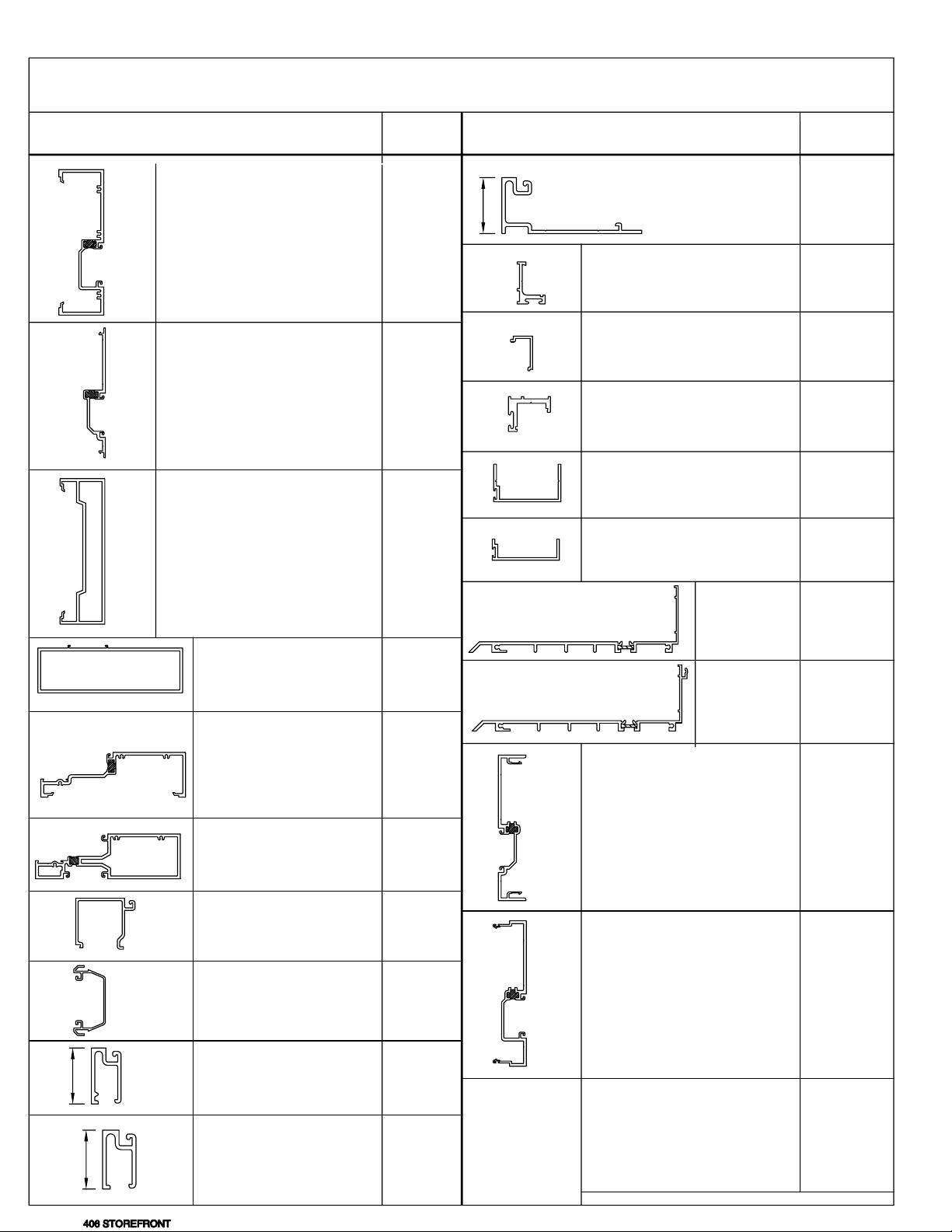
PARTS IDENTIFICA TION.
PART
NO.
1"
9359
9358
8402
8400
9357
8401
DESCRIPTION
APPLIED FIXED SASH
USED w/ 9133 STOP
FOR TRANSOM LITES OVER 4 FT.
AT JAMBS
SCREW APPLIED
JAMB DOOR S TOP
USE w/ 9155 & W138
SCREW APPLIED
DOOR STOP COVER
USE w/ 9154 & W138
5/8" DOOR STOP
AT HEADER
USE w/ 9155 & W138
C.O.C. DOOR STOP
AT HEADER
USE W138 WEATHERING
LCN C.O.C. DOOR STOP
AT HEADER
USE W138 WEATHERING
STD. SILL
FLASHING
SILL
FLASHING
WITH
STOOL CLI P
MALE EXPANSION
MULLION HALF
USE w/ 4461
PART
NO.
9250
9154
9155
4437
9914
9933
1G83
1G86
4462
15
HORIZONTAL GLAZING
STOP, USE WITH
9357 & 8401
TRANSOM JAMB
GLAZING POCKE T
w/ 8402 JAMB
48" CUT OUT MAX .
TRANSOM BAR
1"
"
/
16
GLAZING STOP
1" GLAZING
USE w/ 8400
REMOVABLE STOP
USE w/ 9250 fo r
1" APPLIED GLAZING
FOR TRANSOM LITES OVER
4' AT JAMBS
9229
8403
9123
9133
FEMALE EXPANSION
MULLION HALF
USE w/ 4462
PARTS ON THIS PAGE ARE NOT TO SCALE
4461
MDM 04/2006
Page 5
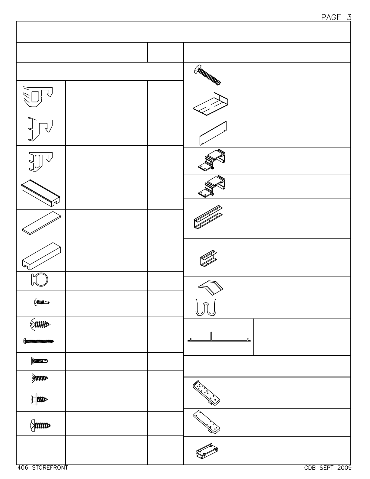
SECTION II
DESCRIPTION
PARTS IDENTIFICATION
PART
NO.
DESCRIPTION
cont.
PART
NO.
ACCESSORIES
GLAZING GASKET for
UNDERSIZED GLASS
3/4" INFILL @ 1" POCKET
GLAZING GASKET for
OVERSIZED GLASS
1 1/8" INFILL @ 1" POCKET
STANDARD GLAZING
GASKET
1" INFILL @ 1" POCKET
EXTERIOR GLAZED
SETTING BLOCK
at SILL & HORIZ.
USE w/ 9357 & 8401
INTERIOR GLAZED
SETTING BLOCK
at HORIZ. INTERMEDIATE
USE w/ 8401
TRANSOM BAR
SETTING BLOCK
1" GLAZING
USE w/ 8400
STANDARD WEATHER
SEAL @ DOOR STOPS
APPLIED DOOR STOP
ATTACHMENT SCREW
USE w/ 9154 & 9155
HORIZ. to
SHEAR BLOCK
SHEAR BLOCK
to VERT.
DOOR HEAD ER
TO SHEAR BLOCK
TRANSOM HEAD
TO SHEAR BLOCK
TRANSOM BAR
SHEAR BLOCK
to VERT.
SILL FLASHING
END CAP
ATTACHMENT SCREW
W165
W166
W164
HN32
HN92
HNA3
W138
STT6
STB9
S100
STK4
S101
STV2
STC7
FRAME SPLINE
ATTACHMENT SCREW
#10 x 1" SL-HW-SMS
SILL FLASHING
SPLICE JOINT PKG.
USE WITH 1G83 & 1G86
(1) FV34, (1) WM96
SILL FLASHING
END CAP PKG.
USE WITH 1G83 & 1G86
(1) FV35, (2) SFP6
HEAD & HORIZONTAL
SHEAR BLOCK PKG.
USE w/ 9359 & 8401
(1) FV 36,(2 ) STB9 , (4) S100, (2) S101
SILL SHEAR BLOCK PKG.
USE w/ 9357
(1) FU49, (1) STB9, (4) S100
TRANSOM BAR
SHEAR BLOCK PKG.
OPP. COC @ SINGLE DR
USE w/ 8400
(1) FV33, (3) STV2, (4) STK4
TRANSOM BAR
SHEAR BLOCK PKG.
USE W/ COC 'F' CLIP or FT16
ANGLE CLIP at CLOSER END
(1) FU31, (2) STV2, (4) STK4
WATER DEFL ECTOR @
INT. HORIZONTAL
5/8" ANTIWALK BLOCK
at DEEP POCKET ONLY
PLASTIC
CAULK BACKER
10 FT. LENGTHS
3" CUT LENGTHS
USED AT FASTENERS
S129
K979
K980
K977
KN65
K978
K996
HWD1
HN52
LB78
FV16
SYSTEM DRILL JIGS
SHEAR BLOCK
DRILL JIG
SCREW SPLINE
DRILL JIG
SHEAR BLOCK
DRILL FIXTURE
(HORIZONTALS to
SHEAR BLOCKS)
DJ16
DJ17
DJ18
Page 6

PAGE 4
SECTION III FABRICATION
A - SCREW SPLINE FABRICATION
The screw spline system is a fabrication and erection method that
permits the preassembly of single units in the shop or at the job site.
These units are then erected by mating the male mullion with the
female mullion counterpart.
When an entrance is required, screw spline joinery may be used with
the screw spline door jambs only.
NOTE)
STEP 1)
NOTE: Allow minimum 1/2" shim and caulk space around the perimeter.
NOTE: Allow extra clearances, if necessary, to accommodate building
NOTE: Consult A.D.A. requirements to verify compliance.
STEP 2)
NOTE: Verticals must run through.
NOTE: The screw spline door jamb runs to the floor and is cut longer
DUE TO THE SCREW TENSIONS REQUIRED FOR CORRECT
INSTALLATION, IT IS NECESSARY TO 'WAX' THE FRAME
ASSEMBLY SCREWS TO PREVENT GALLING AND BREAKAGE.
MEASURE THE OPENING TO DETERMINE THE CUT LENGTH
OF THE FRAME COMPONENTS.
tolerances and building movement.
CUT THE VERTICALS TO FRAME SIZE.
If the opening has an entrance, see the appropriate frame and
door fabrication installation sheets.
than other verticals. The glazing adaptor will be cut to the
STEP 3)
NOTE: Drill jigs are available.
STEP 4)
406 STOREFRONT
standard jamb and vertical intermediate length.
DRILL THE HOLES FOR ASSEMBLY SCREWS ON
VERTICAL MEMBERS. (See Fig. # 1 page 5).
See page 3 of the parts identification section.
CUT THE HORIZONTAL MEMBERS TO DAY LITE OPENINGS.
(BETWEEN VERTICAL MULLIONS)
CUT THE HORIZONTAL GLASS STOPS TO DAYLITE OPENINGS
MINUS 1/32". (D.L.O. - 1/32")
MDM 04/2008
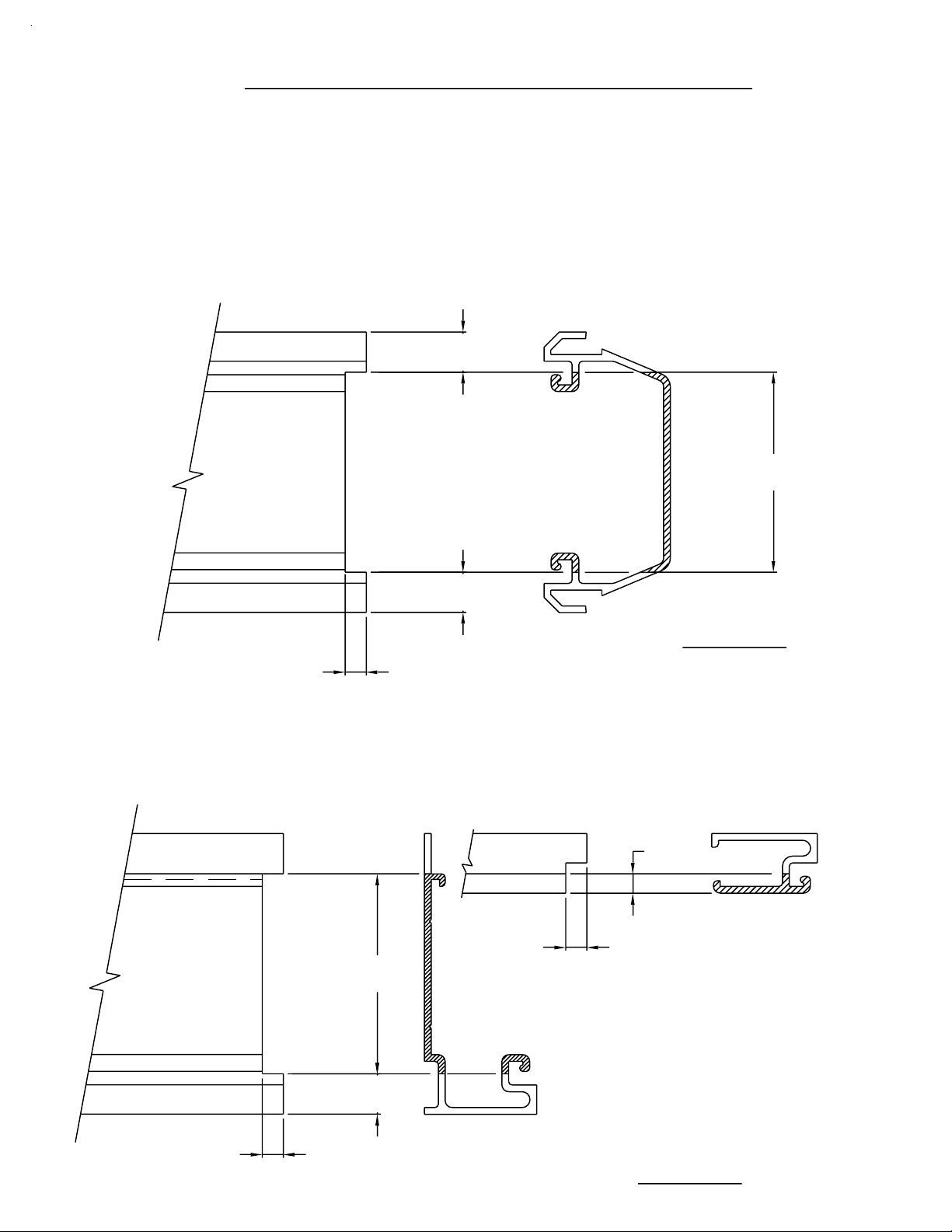
Page 7
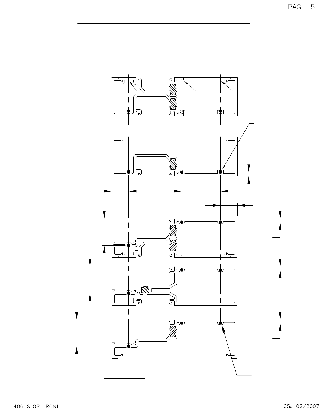
2 PC.
VERTICAL
SECTION III FABRICATION
A - SCREW SPLINE FABRICATION
1) TEMPLATE FOR O. G. SCREW SPLINE
( INVERT FOR I NSIDE GLAZE )
9358
9359
# 7 Drill (.201 dia.)
C
C
L
L
C
L
(3) PLACES TYP.
S129 FASTENERS
(CONT.)
O.G. HEAD
2 PC.
O.G. HORIZONTAL
TUBULAR
O.G. HORIZONTAL
I.G. SILL
.875
I.G. HORIZONTAL
1.367
I.G. HORIZONTAL
1.367
9359
2.000
9357
9358
8401
.188
HEAD
ONLY
.875
.168
.168
9357
1.367
O.G. SILL
I.G. HEAD
FIG. # 1
USE BLOCKED OUT HOLE LOCATIONS FOR O.G. SCREW SPLINE APPLICATIONS
INVERT PATTERN FOR INSIDE GLAZE APPLICATIONS
DRILL JIGS ARE ALSO AVAILABLE
.168
#7 Drill (.201 dia.)
(3) PLACES TYP.
S129 FASTENERS
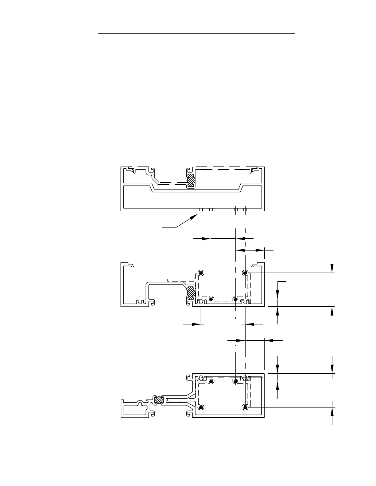
Page 8
SECTION III FABRICATION
A - SCREW SPLINE FABRICATION
2) DJ17 DRILL GUIDE
FOR SCREW SPLINE APPLICATI O N
NOTE: The drill jig is reversible
for left and right positions.
(CONT.)
Use the top edge of the
drill guide to locate the
hole pattern for the screw
2"
6
0
4
F
Insert this lug into the glazing
pocket, then drill the screw
spline assembly holes as
indicated.
splines.
# 7 Drill (.201 dia.),
(3) holes are located
per horizontal end.
Refer to the horizontal
extrusion being used to
determine the correct holes
to drill for the application
at head, intermediate,
or sill.
2"
TYP. VERTICAL
FIG. #2
TOP OF HORIZONTAL
R
O
LO
F
D
HE
S
NI
I
F
O
T
Page 9

PAGE 7
SECTION III FABRICATION
B - SHEAR BLOCKS AT SCREW
SPLINE DOOR JAMB
Because the screw spline door jamb is actually a tubular member,
it will be necessary to shear block the transom bar, the transom
head, and any intermediate horizontal that is being incorporated in
the transom area.
STEP 1)
NOTE: Consult A.D.A. requirements to verify door opening
STEP 2)
NOTE: Door jambs run to the floor and are cut longer than other
STEP 3)
MEASURE THE OPENINGS AND SUBTRACT THE VERTICAL
MEMBER'S SIGHT LINES TO DETERMINE THE HORIZONTAL
FRAME CUT LE NGTHS.
Horizontals and transom bar cut length = D.L.O.
Horizontal glass stop cut length = D.L.O. - 1/32".
Transom bar glass stop cut length = D.L.O. - 25/32"
width compliance.
CUT THE DOOR JAMBS T O RO UG H OP EN I N G MINUS 1/4".
verticals.
DRILL TH E HO L E S F O R T H E SHEAR BLOCK S C REWS ON
THE DOOR JAMBS AS SHOWN ON PAGES 8 THROUGH 13.
STEP 4)
NOTE: Drill jigs are available.
STEP 5)
406 STOREFRONT
PROCEED TO SECTION III C FOR HORIZONTAL TO SHEAR
BLOCK PREPS, AS SH OWN ON PAGES 14 AND 15.
(See page 3 of the parts identification section.
PLEASE REFER TO DOOR, DOOR GLASS, AND
HARDWARE MANUAL (PART #Y01 5), FOR THE DOOR
HINGING PREPS, STRIKE PREPS, AND THRESHOLD PREPS.
THESE PREPS SHOULD BE DONE TO THE DOOR JAMBS
AT THIS TIME FOR EASE OF ASSEMBLY.
CSJ 12/2006
Page 10
SECTION III FABRICATION
PAGE 8
B - SHEAR BLOCKS AT SCREW
SPLINE DOOR JAMB
1) TEMPLATE FOR O.G. SHEAR BLOCKS
HEAD & HORIZONTAL SHEAR BLOCK TO S.S. DOOR JAMB
CAUTION:
Door jambs must run to the floor and are cut longer than other verticals.
Shear blocks are not applicable with 2 pc. horizontal intermediates.
NOTE: (2) pc. horizontal (9357/9358) cannot be shear block assembled.
DOOR JAMB
INVERT #8401 HORIZONTAL FOR I.G. TRANSOM
9358
8402
# 26 Drill (.147 dia.)
(4) PLACES
S100 FASTENERS
C
C
LL
C
C
L
L
1.118
(CONT.)
O.G. HEAD
TUBULAR
O.G. HORIZONTAL
I.G. HEAD
9359
K977
SHEAR BLOCK
PACKAGE
1.300
.340
1.525
2.000
.861
.340
1.525
8401
406 STOREFRONT
FIG. # 3
USE BLOCKED OUT HOLE LOCATIONS FOR O.G. SHEAR BLOCK APPLICATIONS
OUTSIDE GLAZED AS SHOWN, INVERT PATTERN FOR INSIDE GLAZE APPLICATIONS
DRILL JIGS ARE ALSO AVAILABLE
DPS 12/2002
Page 11
SECTION III FABRICATION
PAGE 9
B - SHEAR BLOCKS AT SCREW
SPLINE DOOR JAMB
2) DJ16 DRILL GUIDE
FOR TRANSOM - HEAD AND HORIZONTAL
INTERMEDIATE SHEAR BLOCK APPLICATION
NOTE: The drill jig is reversible
for left and right positions.
2"
F406
Insert this lug into the glazing
pocket, then drill the shear
Use the top edge of the
drill guide to locate the
hole pattern for the shear
blocks.
(CONT.)
# 26 Drill (.147 dia.),
(4) holes are located
per horizontal end.
Refer to the horizontal
extrusion being used to
determine the correct holes
to drill for the application
at head (#9359) or intermediate
horizontal (#8401).
2"
block attachment holes as
indicated.
TYPICAL VERTICAL MEMBER
406 STOREFRONT
TOP OF HORIZONTAL
FIG. #4
TO FINISHED FLOOR
DPS 12/2002
Page 12
SECTION III FABRICATION
PAGE 10
B - SHEAR BLOCKS AT SCREW
(CONT.)
SPLINE DOOR JAMB
3) TEMPLATE FOR TRANSOM BAR SHEAR BLOCK
TO S.S. DOOR JAMB
OPPOSITE A C.O.C. AT A SINGLE DOOR
ALL OTHER STD. 402 DOOR FRAME PREPS WILL APPLY
NOTE:
DOOR JAMB
FOR C.O.C.'S, PIVOTS, AND OTHER HINGING.
9358
#4 Drill (.209 dia.)
(3) Places
STV2 FASTENERS
8400
TRANSOM
BAR
1.150
C
L
3.320
8402
C
L
C
L
8400
1.000
C
FV33
K978
K978
SHEAR BLOCK
PACKAGE
L
406 STOREFRONT
5.220
FIG. # 5
DRILL JIGS ARE ALSO AVAILABLE
DPS 12/2002
Page 13
SECTION III FABRICATION
PAGE 11
B - SHEAR BLOCKS AT SCREW
(CONT.)
SPLINE DOOR JAMB
4) TEMPLATE FOR TRANSOM BAR SHEAR BLOCK
TO S.S. DOOR JAMB
WITH C.O.C. 'F' CLIP OR FT16 ANGLE CLIP
ALL OTHER STD. 402 DOOR FRAME PREPS WILL APPLY
NOTE:
DOOR JAMB
FOR C.O.C.'S, PIVOTS, AND OTHER HINGING.
9358
8400
TRANSOM
BAR
#4 Drill (.209 dia.)
(2) Places
STV2 FASTENERS
C.O.C 'F' CLIP
or FT16 ANGLE
- HERE -
4.750
5.687
8402
CC
L
L
8400
1.000
C
L
K996
SHEAR BLOCK
PACKAGE
406 STOREFRONT
SEE Y013 DORMA C.O.C. INSTALLATION INSTRUCTIONS FOR
DIMENSIONS AND APPLICATIONS FOR THE CLOSER
FIG. # 6
DRILL JIGS ARE ALSO AVAILABLE
DPS 12/2002
Page 14

SECTION III FABRICATION
PAGE 12
B - SHEAR BLOCKS AT SCREW
SPLINE DOOR JAMB
5) DJ16 DRILL GUIDE
TRANSOM BAR SHEAR BLOCK TO DOOR JAMB
OPPOSITE A C.O.C. AT A SINGLE DOOR
NOTE: The drill jig is reversible
for left and right positions.
#4 Drill (.209 dia.),
# 26 Drill (.147 dia.),
(4) holes are located
per shear block.
Use # K977 shear block pkg.
2"
(CONT.)
Use the top edge of the
drill guide to locate the
hole pattern for the shear
blocks.
(3) holes are located
on center, per transom bar end.
This prep is opposite a C.O.C.
at a single door.
Use #K978 shear block pkg.
Locate this block to
the interior edge of
the door jamb.
FIG. #7
406 STOREFRONT
LOCATE TOP EDGE OF
DRILL JIG AT THE
TOP OF THE T-BAR
TO FINISHED FLOOR
DPS 12/2002
Page 15

SECTION III FABRICATION
PAGE 13
B - SHEAR BLOCKS AT SCREW
SPLINE DOOR JAMB
6) DJ16 DRILL GUIDE
TRANSOM BAR SHEAR BLOCK TO DOOR JAMB
WITH A C.O.C - SINGLE OR PAIRS OF DOORS
NOTE: The drill jig is reversible
for left and right positions.
#4 Drill (.209 dia.),
# 26 Drill (.147 dia.),
(4) holes are located
per shear block.
Use # K977 shear block pkg.
2"
(CONT.)
Use the top edge of the
drill guide to locate the
hole pattern for the shear
blocks.
(2) holes are located
on center, per transom bar end.
This prep is in conjunction with
the C.O.C. 'F' clip or FT16 angle.
Use #K996 shear block pkg.
Locate this block to
the interior edge of
the door jamb.
FIG. #8
406 STOREFRONT
LOCATE TOP EDGE OF
DRILL JIG AT THE
TOP OF THE T-BAR
TO FINISHED FLOOR
DPS 12/2002
Page 16

SECTION III FABRICATION
C- SHEAR BLOCK FABRICATION - FRAMES
1) DJ18 DRILL GUIDE APPLICATION
AT TUBULAR INTERMEDIATE HORIZONTAL
AND OPEN BACK SILL
LOCATE ON
GUIDE TRACK
HORIZONTAL AND SILL END
PREP FOR ATTACHMENT TO
.567
2.656
.221 DIA.
DRILL
SHEAR BLOCKS
PAGE 14
1.000
K977 FOR 8401 HORIZ./SILL
KN65 FOR 9357 SILL
DJ18
Fig. #9
Drill as indicated thru one
wall using #2 drill (.221 Dia).
#8401 AT HORIZONTAL
406 STOREFRONT
.221 DIA.
DRILL
DJ18
Fig. # 10
DPS 4/2004
Page 17

PAGE 15
SECTION III FABRICATION
C- SHEAR BLOCK FABRICATION - FRAMES
(CONT.)
2) DJ18 DRILL GUIDE APPLICATION
AT OPEN BACK TRANSOM HEAD
TRANSOM HEAD END PREP FOR ATTACHMENT TO SHEAR BLOCKS
C
L
.875
REF.
C
L
2.656
.221 DIA.
DRILL
1.000
2.656
.221 DIA.
DRILL
EXTERIOR
Fig. # 11
.221 DIA.
DRILL
DJ18
#9359 AT TRANSOM HEAD
Drill as indicated thru one
wall using #2 drill (.221 Dia)
406 STOREFRONT
EXTERIOR
.221 DIA.
DRILL
DJ18
Fig. # 12
DPS 12/2002
Page 18
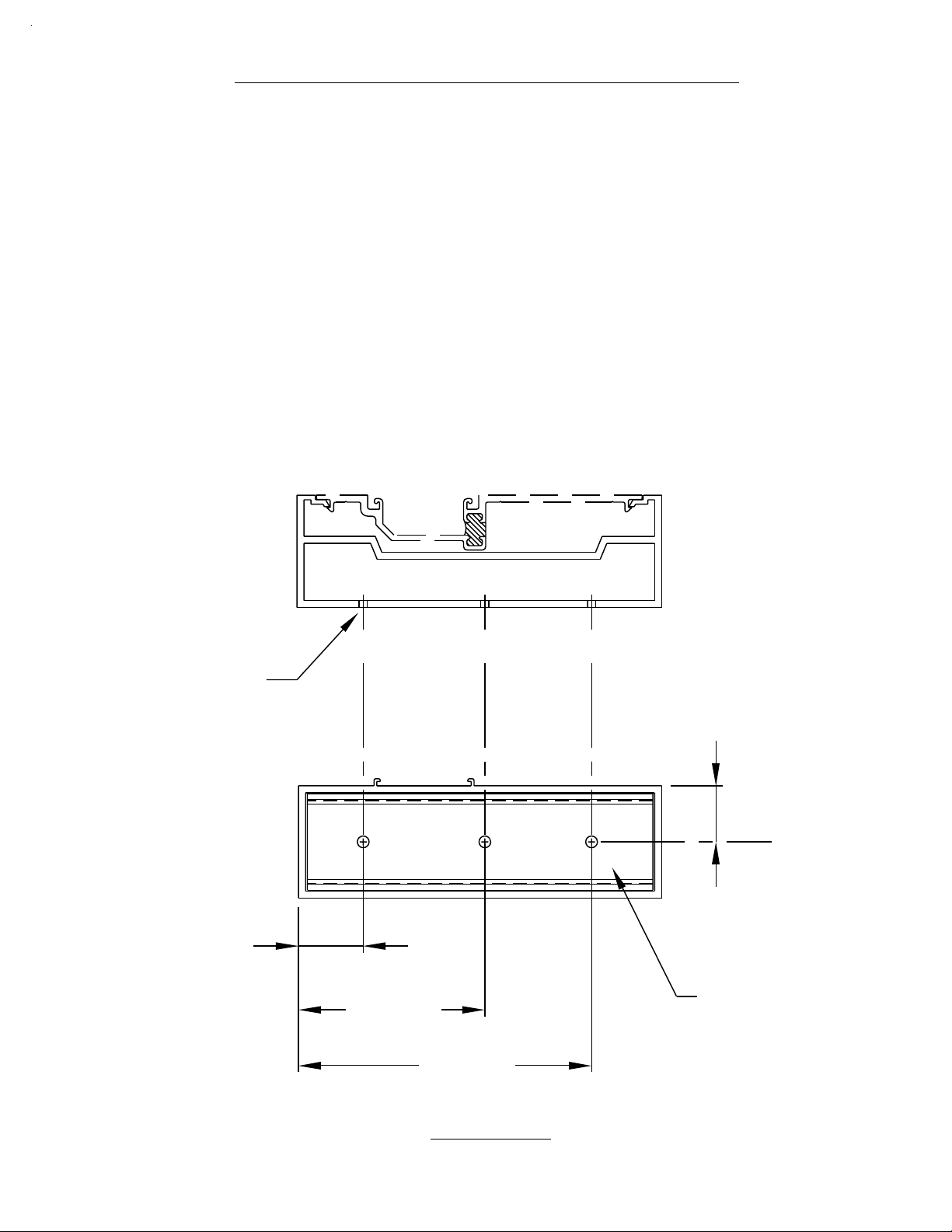
SECTION III FABRICATION
D - SNAP-IN GLAZING POCKET &
SCREW APPLIED GLAZING
1) SNAP-IN GLAZING POCKET END PREP
.358
PAGE 16
#8403
THIS END
TO TRANSOM BAR
1.780
.358
Fig. # 13
CUT LENGTH =
VERTICAL D.L.O. - 1/32"
.188
NOTE:
NOTCH THROUGH GLAZING TRACKS AND
BACK WALL OF PART AS SHOWN.
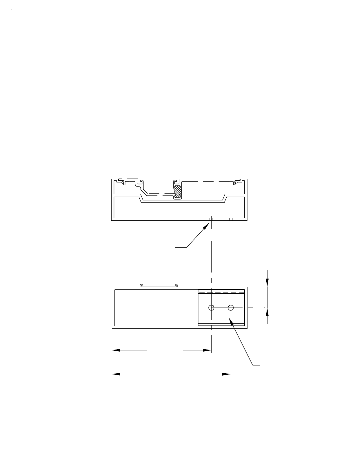
2) SCREW APPLIED GLAZING END PREPS
.173
#9133
406 STOREFRONT
.188
1.781
THIS END
TO TRANSOM BAR
.358
.188
CUT LENGTHS =
VERTICAL D.L.O. - 1/32"
#9250
Fig. # 14
DPS 12/2002
Page 19

PAGE 17
SECTION IV ASSEMBLY & INSTALLATION
A - DOOR FRAME ASSEMBLY
NOTE: If an entrance frame is required, it must be installed first.
Attach the transom bar to the jamb with the #K978 shear block
or the K996 and the 'F' clip or angle bracket (#FT16) for a C.O.C.
Be sure the snap-in glazing pocket has been notched to clear the
glazing stop tracks on the top of the transom bar.
Please see page 16 for this end prep.
HEAD SHEAR
BLOCK PREP
See #Y013 for Dorma C.O.C. Installation Instructions.
See #Y014 for International C.O.C. Installation Instructions.
8402 DOOR JAMB
If the jambs are not factory prepped, please
see page 18 for transom jamb glazing pocket cut out.
K978 PKG.
K996 SIM.
Apply sealant to the
end of the transom bar
before attaching it to
the shear block.
8400
TRANSOM BAR
406 STOREFRONT
THIS ASSEMBLY IS
OPPOSITE A C.O.C.
AT A SINGLE DOOR.
SEE PAGE 23
Factory prep shown.
Fig. # 15
DPS 12/2002
Page 20

PAGE 18
SECTION IV ASSEMBLY & INSTALLATION
A - DOOR FRAME ASSEMBLY
(CONT.)
NOTE: If an entrance frame is required, it must be installed first.
The transom jamb glazing pocket will snap into the cut out cavity.
The glazing pocket will flush with the top of the transom bar or with
the top of the horizontal intermediate, if used.
HEAD SHEAR
BLOCK PREP
The cut out must not
exceed 48" in length.
See page 20 for lengths
greater than 48".
1.188
3.313
TOP OF
TRANSOM BAR
8402 DOOR JAMB
8403 TRANSOM JAMB
GLAZING POCKET
See page 16 for end prep.
SEE PAGE 23
FOR THIS PREP
406 STOREFRONT
Fig. # 16
DPS 12/2002
Page 21

PAGE 19
SECTION IV ASSEMBLY & INSTALLATION
A - DOOR FRAME ASSEMBLY
#8403
#K977
#K978
EXPLODED VIEW
(CONT.)
#9359
#8402 DOOR JAMB
FACTORY PREP SHOWN
Fig. # 17
#8400
#9954/#9955 DOOR STOP
THIS ASSEMBLY IS
OPPOSITE A C.O.C.
AT A SINGLE DOOR.
406 STOREFRONT
DPS 12/2002
Page 22

PAGE 20
SECTION IV ASSEMBLY & INSTALLATION
A - DOOR FRAME ASSEMBLY
FOR TRANSOM D.L.O. OVER 48" USE #9250 AND #9133
APPLIED GLAZING AT JAMB APPLIED STOPS RUN THROUGH
AT TRANSOM BAR GLAZING STOPS.
CUT LENGTH = VERTICAL D.LO. - 1/32".
EXPLODED VIEW
SEALANT IN
CAVITY
#K9250 / #9133
See page 16 for end prep.
APPLY SEALANT TO
ALL HORIZONTAL ENDS
#K977
BEFORE ASSEMBLY
(CONT.)
#8402 DOOR JAMB
FACTORY PREP SHOWN
#9359
#K978
#8400
#9954/#9955 DOOR STOP
406 STOREFRONT
Fig. # 18
THIS ASSEMBLY IS
OPPOSITE A C.O.C.
AT A SINGLE DOOR.
DPS 12/2002
Page 23

PAGE 21
SECTION IV ASSEMBLY & INSTALLATION
A - DOOR FRAME ASSEMBLY
DORMA RTS 88 w/ BUTT HINGES,
GEARED HINGES &
#8403
DUAL ACTING
#K977
EXPLODED VIEW
(CONT.)
#9359
F CLIP
(BY DORMA)
F045
#8402 DOOR JAMB
FACTORY PREP SHOWN
#K996
#8400
#9954/#9955 DOOR STOP
406 STOREFRONT
Fig. # 19
REFER TO Y013 DORMA RTS 88
INSTALLATION INSTRUCTIONS
DPS 12/2002
Page 24

PAGE 22
SECTION IV ASSEMBLY & INSTALLATION
A - DOOR FRAME ASSEMBLY
DORMA RTS 88 w/ OFFSET PIVOTS
#8403
#K977
#9359
(CONT.)
FT16
F045
#8402 DOOR JAMB
FACTORY PREP SHOWN
#K996
#8400
#9954/#9955 DOOR STOP
406 STOREFRONT
REFER TO Y013 DORMA RTS 88
INSTALLATION INSTRUCTIONS
Fig. # 20
DPS 12/2002
Page 25

PAGE 23
SECTION IV ASSEMBLY & INSTALLATION
B - DOOR FRAME INSTALLATION
NOTE: If an entrance frame is required, it must be installed first.
STEP 1)
STEP 2)
STEP 3)
STEP 4)
CORRECTLY LOCATE THE ENTRANCE FRAME IN THE OPENING.
APPLY A BEAD OF SEALANT AROUND THE INTERIOR PORTION OF
THE JAMB TO SET THE MEMBER INTO. THEN MARRY THE SIDE LITE
SEALANT OR CONDITION SEALANT INTO THE BEAD OS SEALANT TO
BE APPLIED UNDER THE THRESHOLD. THE CONCEPT IS TO HAVE A
CONTINUOUS BEAD OF SEALANT AT THE INTERIOR, CONNECTED
FROM THE SILL FLASHING/CONDITION THROUGH THE DOOR JAMB
AND CONTINUING UNDER THE THRESHOLD TO THE OPPOSITE JAMB
AND SO ON.
SET THE ASSEMBLED DOOR FRAME IN THE OPENING,
PLUMB AND LEVEL.
ANCHOR THE DOOR FRAME AS INDICATED BELOW AND IN
FIG. #22 THROUGH FIG. #25 ON PAGE 24.
#9357/1G83
SIDE LITE SILL
& FLASHING
NOTE:
The door jamb runs to the
floor and is cut longer
than any other vertical
member.
K-124/K-125 Threshold Clip & Screws
@ Offset Pivots & Butt Hinges
K-153/K-154 Threshold Clip & Screws
@ Concealed Rod Panic
THRESHOLD
(9950)
#8402
Continuous bead
of sealant to tie into
underside of sill.
Fig. # 21
406 STOREFRONT
DPS 12/2002
Page 26

PAGE 24
SECTION IV ASSEMBLY & INSTALLATION
B - DOOR FRAME INSTALLATION
At the open back head and jamb, EFCO
recommends using full lengths of caulk
backer (LB7 8) or use 3" pieces (FV16) and
locate them at the frame and door frame
anchors. This is to prevent collapsing the
glazing pocket s or distorting the door jamb.
9359 frame jamb & 9357 frame sill require
LB78/FV16 similar.
Fig. # 22
#8402 SHOWN
LB78/FV16
(CONT.)
LB78/FV16
#9359
Anchor through the transom head/frame head
glazing pocket with flat head screws located
6" from the ends and 16" on center,
maximum spacing.
Fig. # 23
Anchor through the S.S. jamb at
the door stop centerline with flat head
screws located 6" from the ends and
16" on center, maximum spacing.
EXTERIOR
INTERIOR
Fig. # 25
#8400
Fig. # 24
Anchor through the transom bar at
the door stop centerline with flat head
screws located 6" from the ends and
16" on center, maximum spacing.
Attach through the threshold
with flat head screws
located 6" from the ends and
15" on center, typical spacing.
Continuous bead of sealant at
the back of the threshold and sides of
the jambs and tied into mullion sealant
at the condition.
NOTE: These are general anchor locations. It may be necessary to use 9358 as the
perimeter filler if structural loads require a greater shear strength at the anchor locations.
All projects should be reviewed by a structural engineer for exact anchoring requirements
Page 27

PAGE 25
SECTION IV ASSEMBLY & INSTALLATION
C - SILL FLASHING INSTALLATION
STEP 1)
Sealant
INSTALL THE SILL FLASHING CONTINUOUSLY BETWEEN
THE MASONRY JAMBS OR BETWEEN THE DOOR FRAME
AND THE MASONRY JAMB. SEE FIGURES BELOW.
Anchor the sill flashing 6" from verticals
and 24" O.C. Before the fastener is
Sealant
inserted, force sealant into the hole
to ensure that the hole through the sill
flashing is sealed.
Sill flashing optio ns:
THERMAL
1G83 - STANDARD
{
1G86 - w/ STOOLS
Sealant
Shim the flashing
until it is level and
set it in a continuous
bead of sealant.
FIG. #26
NOTE:
Seal over the heads of all
flashing attachment screws.
Seal the ends of the flashing with a
"skinning", nonhardening type of
sealant (i.e., silicone).
ALL THERMAL STRUT SILL FLASHING THAT COULD
ENCOUNTER MOISTURE MIGRATION MUST HAVE THE
THERMAL STRUT SEALED OVER WITH SILICONE.
Apply a continuous bead of sealant
across the top of the thermal strut
when using thermal flashing.
1G83 SHOWN,
1G86 SIMILAR.
FIG. #27
8731
9738
Page 28

PAGE 26
SECTION IV ASSEMBLY & INSTALLATION
STEP 2)
C - SILL FLASHING INSTALLATION
INSTALL THE SILL FL ASHING IN A CONTINUOUS BEAD OF
SEALANT BETWEEN THE MASONRY JAMB AND THE DOOR
FRAME. THE BEAD OF SEALANT WILL TIE INTO THE SEALANT
THAT FILLS THE CAVITY IN THE DOOR JAMB AND TIES INTO THE
BEAD OF SEALANT THAT THE THRESHOLD IS SET INTO. SEAL
THE END OF THE SILL FLASHING TO THE DOOR JAMB
THOROUGHLY. FILL THE HOLLOW AREA OF THE DOO R JAMB
WITH SEALANT LEVEL WITH THE SILL FLASHING TO DIVERT ANY
WATER ONTO THE SILL FLASHING. SEE FIGURE BELOW.
SEAL FLASHING
(CONT.)
APPLY SEALANT JUST
BEFORE SETTING THE
SILL MEMBER
TO JAMB
Fill this cavity with
sealant, level with the
sill flashing.
SEAL THIS AREA OF THE
SILL FLASHING
SEAL OVER THERMAL STRUT
CONTINUOUS BEAD
OF SEALANT TO THE
MASONRY JAMB
OPTIONAL SEALANT
FIG. #28
Page 29

PAGE 27
SECTION IV ASSEMBLY & INSTALLATION
C - SILL FLASHING INSTALLATION
VIEW OF JAMB AT CONDITION
#9359
#9358 CONTINUOUS SHOWN
OR LB78/FV16 VINYL NOT SHOWN
#9357
The sill flashing must be sealed to the condition
and the jamb member set in a bead of sealant
to ensure a water tight seal.
SEALANT
(CONT.)
FIG. #29
STEP 3)
INCORPORATING THE SILL FLASHING END CAPS WILL COMPLEMENT
THE SEALING PROCEDURE. THE END CAPS MUST BE SEALED TO THE
CONDITION AND THE SEALANT MUST TIE-IN WITH THE JAMB BLOCKING
AND THE PERIMETER SEALS. THE END CAP EDGES MUST ALSO BE
CONCEALED WITH THE SEALANT TO PRESENT A NEAT CLEAN
INSTALLATION. THIS MAY CAUSE THE CAULK JOINT AT THE JAMB TO
INCREASE IN THICKNESS, IF THE CONDITION IN IRREGULAR.
406 STOREFRONT
K980
DPS 12/2002
Page 30

SECTION IV ASSEMBLY & INSTALLA TION
STEP 4)
C - SILL FLASHING INSTALLATION
(CONT.)
SILL FLASHING CUT LENGTH = ROUGH OPENING MINUS 1/2" WITH END
CAPS. END CAPS WOULD BE INCORPORATED IF THE SILL FLASHING
COULD NOT BE SEALED TO THE CONDITION COMPLETELY. AN EXAMPLE
WOULD BE, IF THE JAMB CONDITION IS LESS THAN THE SILL FLASHING
DEPTH OR IF THERE IS A VOID IN THE CONDITION.
Sealant
K980
Sealant
for # 1G83
& # 1G86
FIG. #30
STEP 5)
Anchor sill flashing
6" from verticals and
24" O.C. and seal
over all screw heads.
Set sill flashing splice in a bed
of sealant around the perimeter
of the splice.
SPLICE THE FLASHING EVERY 20'-0" AS SHOWN IN FIG. #31 BELOW. USE
K979 FOR S406 HIGH PERFORMANCE FLASHING. IT IS NOT ADV I S E D TO
LOCATE THE SPLICE JOINT DIRECTLY AT A VERTICAL INTERMEDIATE.
ALLOW 6" MINIMUM SPACING FROM THE VERTICALS. FOR MITERED
CORNERS, SEE PAGE 29.
Reapply sealant across the splice
when in place to ensure the
bead of sealant is continuous.
FIG. #31
Bond breaker tape
1" wide centered on
back of splice.
K979
.050 aluminum
formed sleeve
After the splice is in place, apply
the cosmetic seal to the
3
/
8
"
Use backer rod and
silicone to fill the joint
in the sill flashing.
interior gap vertically.
Page 31

PAGE 29
SECTION IV ASSEMBLY & INSTALLATION
STEP 6)
1 1/2"
C - SILL FLASHING INSTALLATION
(CONT.)
IF A CORNER IS REQUIRED, MITER THE FLASHING TO THE
REQUIRED ANGLE AND THEN INSTALL AS SHOWN IN THE FIGURES
BELOW. LOCATE FASTENERS 3" AWAY FROM ANY CORNER AND 1
1/2" FROM THE EDGE OF THE SILL FLASHING SPLICE.
Cover the heads of all
6" MIN.
1 1/2"
K979
attachment screws
with sealant.
SEALANT
12" MIN.
TO SPLICE JOINT
TYP.
3/8"
12" MIN.
TO SPLICE JOINT
3"
TYP.
FIG. #32
# 1G83 sill flashing shown,
SEALANT
3"
Cover the heads of all
attachment screws with sealant.
# 1G86 is similar.
FIG. #33
406 STOREFRONT
# 1G83
DPS 12/2002
Page 32

PAGE 30
SECTION IV ASSEMBLY & INSTALLATION
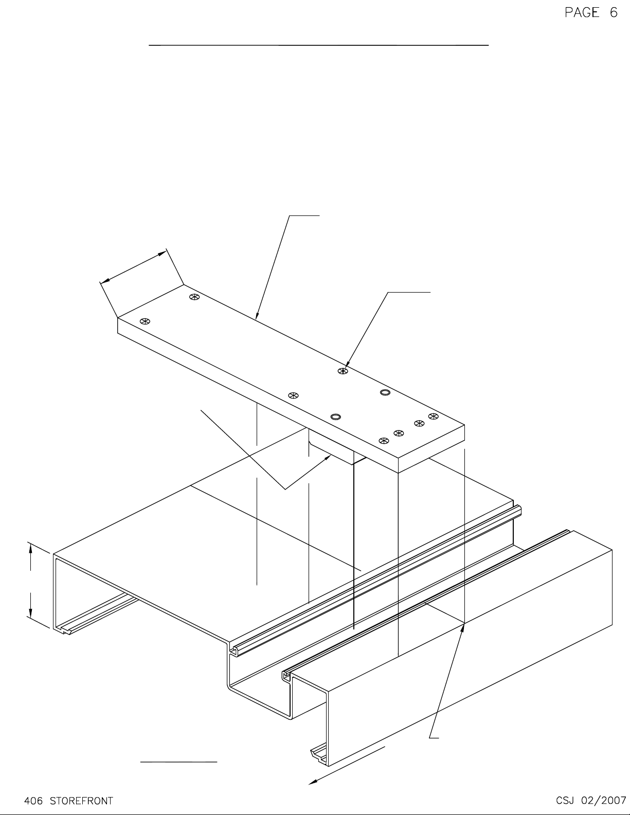
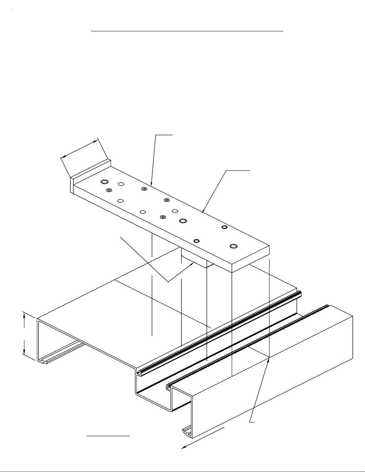
D - SCREW SPLINE FRAME & SIDE LITE TO
DOOR JAMB ASSEMBLY
#9359 JAMB
NOT SHOWN
FOR CLARIT Y
LB78/FV16 PERIMETER
FILLERS NO T SHO W N
FOR CLARITY.
(REQUIRE D @ HE AD , J A MB
& SILL)
#8401 HORIZ. SHOWN
#9357/#9358 SIMILAR
#9359 HEAD
APPLY SEALANT TO
THE ENDS OF ALL
HORIZONT ALS BEFOR E
ASSEMBLY.
#9358 SHOWN at
DOOR JAMB
WAX ALL SCREW S
S129
ASSEMBLY SCREWS
S129
APPLY SEALANT TO
SNAP AREA AT TH E
INTERIOR AND
EXTERIOR.
#9357 SILL
SILL FLASHING
NOT SHOWN
S129
FIG. #34
WAX ALL SCREW S
NOTE: THE SILL FLASHING ENDS AT A DOOR JAMB.
THE SILL FLASHING RUNS THRU AT JAMBS
AND VERTICAL I NT ER M E DIATES.
NOTE: Use full lengths of LB78 perimeter adaptor at the head and jambs as a caulk backer
and to keep from collapsing the glazing pocket. Use 3" lengths of LB78 perimeter adaptor
S129
(FV16) at the sill member and locate them at the fastener, to keep the anchors or weight of
the glazing material from collapsing the glazing pocket.
Page 33

PAGE 31
SECTION IV ASSEMBLY & INSTALLATION
D - SCREW SPLINE FRAME & SIDE LITE TO
DOOR JAMB ASSEMBLY
EXPLODED VIEW
(CONT.)
NOTE: #9358 GLAZING ADAPTOR
IS THE SAME LENGTH AS THE
STANDARD #9359 JAMB.
NOTE:
Make sure the bead of sealant under the threshold is continuous
through the door jamb and married into the bead of sealant that the
sill flashing is set into.
406 STOREFRONT
FIG. #35
DPS 12/2002
Page 34

PAGE 32
SECTION IV ASSEMBLY & INSTALLATION
E - WATER DEFLECTOR INSTALLATION
Water deflectors are used at the ends of all horizontal intermediates to prevent
any accumulated moisture in the glazing pocket from dropping on the top edge
of the 1" glass unit below.
HWD1 WATER DEFLECTOR
#9359/#9358
Apply a thin coat of silicone sealant to the end of
the horizontal. Set the HWD1 into the sealant
and allow to cure prior to installing glass.
Seal the horizontal to the vertical at
the inside face of the glazing pocket.
#8401
Seal over the attachment screws,
FIG. #36
406 STOREFRONT
This end extends into
the vertical glazing pocket
and over the lower glass
unit's corner.
if shear block, and across the
horizontal joint for shear block or
screw spline
TYP. VERTICAL
HWD1 WATER DEFLECTOR
TYP. HORIZONTAL
GLASS UNIT BELOW
FIG. #37
DPS 12/2002
Page 35

SECTION V GLAZING
A - GLASS SIZE FORMULAS
System 406 (2" sight line) = D.L.O. + 7/8" (HORIZONTAL)
System 406 (2" sight line) = D.L.O. + 7/8" (VERTICAL)
TRANSOM LITE
9358/8402/8403
2.000
D.L.O.
PAGE 33
9359
2.000
2.000
.375
1.000
D.L.O.
9250/9133
D.L.O.
9358/9359
.375
1.000
2.000
2.000
2.000
8401
D.L.O.
1.000
2.000
8400
Fig. # 39
2.000
406 STOREFRONT
D.L.O.
Fig. # 38
2.000
DPS 12/2002
Page 36

SECTION V GLAZING
B - GLASS INSTALLATION
STEP 1) GASKET INSTALLATION FOR OUTSIDE GLAZE.
A) Apply sealant to the ends of all horizontals to seal the intersections
at the verticals. At all 4 corners of the D.L.O., apply sealant in the gasket race
1" away from the intersection of the vertical and horizontal members.
See detail # 40 below.
B) Cut the interior and exterior push-in gasket to an approximate length of
D.L.O. x 1.02 (DLO PLUS 2%).
C) Install the interior glazing gasket. NOTE: The vertical gaskets run through.
D) Start at the ends an d wo rk toward the center , fi rm ly pushing the
gasket in place.
DO NOT STRETCH THE GA SK ET O R IT WILL RETURN TO ITS ORIGINAL
FORM, CREATING GAPS AT THE GASKET INTERSECTIONS.
E) Clean the glaz in g ga skets with denat ur ed alcohol at the intersection area.
Apply a small amount of sealant at the interse ct area to marr y the ver tical
and horizontal glazing gaskets. Tool all sealant to present a neat,
clean appear ance.
NOTE:
These steps are included in the test lab procedure and are requirements
to achieve th e te st rep or t results for air an d wa te r infiltration.
#9359/#9358
1"
1"
SEALANT IN INTERIOR GASKET RACE
1" FROM INTERSECTION
TYPICAL ALL 4 CORNERS OF DLO.
GASKET RACE
Sealant
W164
#8401
SEAL UNDER THE GASKET TRACK
OF THE HORIZ. & MARRY SEALANT
INTO VERTICAL GASKET TRACK &
HWDI @ INT. HORIZ. ONLY.
Fig. # 40
Page 37

SECTION V GLAZING
B - GLASS INSTALLATION
STEP 1) GASKET INSTALLATION FOR OUTSIDE GLAZE
TRANSOM BAR GLAZING STOP SEAL.
PAGE 35
(CONT.)
#8402 DOOR JAMB
w/ #9358 GLAZING
ADAPTOR
Seal the interior glass stop leg to
the transom bar and seal the end
joint to the jamb and transom bar
completely.
Exterior glass stop shown in place,
remove to set the glass unit.
Do not seal the exterior glass stop,
this will allow weepage.
#8403 SNAP-IN
GLAZING POCKET
(48" MAX.)
APPLY SEALANT IN GASKET RACE
1" FROM INTERSECTION
TYPICAL ALL 4 CORNERS OF D.L.O..
# 9123 GLASS STOP
CUT LENGTH = D.LO. - 13/32".
#8400
NOTE:
IF SCREW APPLIED GLAZING STOPS ARE USED VERTICALLY INSTEAD OF
THE SNAP-IN GLAZING POCKET, THE SEALING SCENARIO WILL BE THE
SAME. BE SURE TO SET THE GLAZING BASE IN A BEAD OF SEALANT
BEFORE ATTACHING IT TO THE DOOR JAMB.
406 STOREFRONT
Fig. # 41
RAM 4/2004
Page 38

SECTION V GLAZING
PAGE 36
B - GLASS INSTALLATION
(CONT.)
STEP 2) GLASS INSTALLATION
A) Position the glass unit in front of the opening to be glazed. Lift the unit
to just clear the sill stop area, and then shift the glass into the deep pocket.
B) Swing the opposite edge of the glass around to align with the glazing
pocket.
C) Shift the glass into the shallow pocket until there is equal glass bite
on both edges of the glass.
NOTE:
If using antiwalk blocks,
refer to page 38.
C
A
B
406 STOREFRONT
Fig. # 42
DPS 12/2002
Page 39

SECTION V GLAZING
7
B - GLASS INSTALLATION
STEP 2) GLASS INSTALLATION
D) Lift the glass into the he ad member's glazing pocket.
E) Insert the setting blocks under the glass at the proper locations, typically
1/4 points of the D.L.O. Then lower the glass onto the setting blocks.
F) Snap on the remo vable glass stop and install the exterior glazing gasket.
PAGE 3
LB78 full length/FV16 3" clip
D
E
F
9359
9357
FV16 3" clip
1G83
Fig. # 43
Page 40

SECTION V GLAZING
C - ANTIWALK BLOCK INSTALLATION
STEP 1) ANTIWALK BLOCK INSTALLATION
A) Install the interior gasket following the
steps on page 34.
B) Position the glass as described in the
steps on pages 36 and 37.
C) Stretch the antiwalk block as shown
in Fig. 44 below, and insert it from the
exterior at midlite and deep pocket
side only.
PAGE 38
D) Recenter the glass unit to maintain
equal glass bite all around.
E) Install the exterior gasket.
HN52
ANTIWALK BLOCK
406 STOREFRONT
FIG. # 44
DPS 12/2002
Page 41

SECTION V GLAZING
PAGE 39
C - ANTIWALK BLOCK INSTALLATION
STEP 2) ANTIWALK BLOCK DEGLAZING
A) Remove the interior and exterior glazing gaskets.
B) Push the glass back to the interior side.
C) Remove the antiwalk block with a sharp
hook shaft tool from the exterior side.
(CONT.)
406 STOREFRONT
ANTIWALK BLOCK
REMOVE FROM THIS SIDE
GASKETS REMOVED
EXTERIOR
FIG. # 45
DPS 12/2002
 Loading...