

Page 1

SERIES 403x
Installation Instructions
Part NO. Y022
August 2013
Page 2

Series 403X Storefront Installation Instructions
Table of Contents
Section Page
1. General Notes and Guidelines………………………………………………………………….
2. Parts Identification Charts………………………………………………………………………
3. Fabrication and Assembl y………………………………………………………………………
A. Screw Spline Fabrication………………………………………………………………..
B. Shear Block Fabrication…………………………………………………………………
C. Corner Fabrication………………………………………………………………………..
D. Expansion Mullions………………………………………………………………………
E. Steel Reinforcing………………………………………………………………………….
F. Unit Assembly……………………………………………………………………………..
4. Installation………………………………………………………………………………………….
A. Door Frame Installation………………………………………………………………….
B. Sill Flashing Installation…………………………………………………………………
C. Screw Spline and Shear Block System Installation………………………………...
5. Glazing……………………………………………………………………………………………...
A. Water Deflector Installation……………………………………………………………..
B. Pocket Dimensions and Glass Size Formulas……………………………………….
C. Glazing……………………………………………………………………………………...
D. Window Adaptors & Glazing Adaptors..……………………………………………...
3
4-7
8-9
10-12
13-14
15
16
17-18
19
20-22
23-24
25
25
26-28
29
For additional information see the following Supplements:
Dorma RTS88 Concealed Overhead Closers ……………………………………….Y013
Door, Door Glass and Hardware………………………………………………………Y015
Minimizing Condensation
Note: Please reference EFCO’s “Understanding Condensation” brochure which can be obtained through your EFCO representative.
Condensation will form on any surface when unfavorable conditions (regarding interior temperature, relative humidity and exterior
temperature) are present. When the formation of excessive condensation is a concern, it is highly recommended that a design professional is utilized
to perform an analysis of the shop drawings to recommend the best possible installation methods. Please contact your EFCO representative for
information on EFCO’s Thermal Analysis Services.
Many current installation practices lead to an increase in the possibility of the formation of condensation. Though not all inclusive, the list of
examples below illustrates conditions under which condensation is likely to occur:
1. Bridging the system thermal break with non-thermally broken metal flashing or lintels that are exposed to the exterior
2. System exposure to cold air cavities
3. Interior relative humidity levels not maintained at recommended levels, see EFCO’s “Understanding Condensation” brochure
4. Inadequate separation between system and surrounding condition at perimeter
5. Product combinations during the shop drawing stage that result in bridging thermal breaks of one or all products involved
EFCO 2013 Page 2
Page 3

Series 403X Storefront Installation Instructions
Section 1. General Notes
HANDLING / STORING / PROTECTING ALUMINUM
The following guidelines are recommended to ensure early acceptance of your products and workmanship.
A. HANDLE CAREFULLY - Store with adequate separation between components so the material will not rub together.
Store the material off the ground. Protect materials against weather elements and other construction trades.
B. KEEP MATERIAL AWAY FROM WATER, MUD, AND SPRAY - Prevent cement, plaster, and other materials from
contacting with and damaging the finish. Do not allow moisture to be trapped between the finished surface and the
wrapping material.
C. PROTECT MATERIALS AFTER ERECTION - Wrap or erect screens of plastic sheeting over material. Cement,
plaster, terrazzo, and other alkaline materials are very harmful to the finish and are to be immediately removed with
soap and water. Under no circumstances should these materials be allowed to dry or permanent staining may
occur.
GENERAL GUIDELINES
The following practices are recommended for all installations
A. REVIEW CONTRACT DOCUMENTS – Become thoroughly familiar with the project. Check shop drawings,
installation instructions, architectural drawings and shipping lists. The shop drawings take precedence and inclu de
specific details for the project. Shop drawings govern when conflicting information exists in the assembly an d
installation instructions. Note any field verified notes on the shop drawings prior to installing. EFCO assembly and
installation instructions are general in nature and cover only some of the conditions.
B. INSTALL ALL FRAMING MATERIAL PLUMB, LEVEL, AND TRUE – Proper alignment and relationships to
benchmarks and column centerlines, as established by the architectural drawings and the general contractor, must
be maintained.
D. PERIMETER CONDITIONS - Verify that all job site co nditions and accompanying substrates receiving the
installation are in accordance with the contract documents. If deviations occur, notification must be given in writing
to the general contractor and differences resolved before proceeding further with the installation in the area in
question.
E. ISOLATION OF ALUMINUM - Prevent all aluminum from coming in direct contact with masonry or dissimilar
materials by means of an appropriate primer. Typical slab anchors may be set directly onto concrete surfaces in a
block-out pocket at the edge of the slab. The block-out pocket is later filled in with grout thereby covering the slab
anchor. In such cases, a heavy coat of zinc chromate or bituminous paint must be pre-applied to the slab anchor.
F. SHIPMENT VERIFICATION - Verify contents of all material shipments received upon their arrival. Verify quantity
and correct finishes. Notify EFCO immediately of any discrepancies or damage that may have occurred.
G. SEALANT - All sealant must meet [ASTM C 920, CLASS 50]. For the purposes of these instructions, sealant is to
be defined as the following: SEALANT - A weather resistant, gunnable liquid filler which when cured provides a
resilient, flexible (± 50% movement capability min.) air and water seal between similar and dissimilar materials.
All sealant must be compatible with all surfaces on which adhesion is required, including other sealant surfaces. All
frame surfaces should be clean, dry, dust, and frost free. If a primer is required, it must be applied to clean surfaces.
All perimeter substrates shall be clean and properly treated to receive sealant. All sealants and primers must be
applied according to the sealant manufacturers instructions and recommendations. It is the resp onsibility of the
glazing contractor to submit a statement from the sealant manufacturer indicating that glass and glazing materials
have been tested for compatibility and adhesion with glazing sealants, and interpreting test results relative to
material performance, including recommendations for primers and substrate preparation required to obtain adhesion.
The chemical compatibility of all glazing materials and framing sealants with each other and with like materials used
in glass fabrication must be established.
EFCO 2013 Page 3
Page 4
Series 403X Storefront Installation Instructions
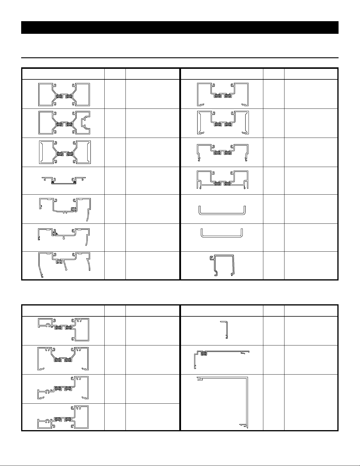
Section 2. Parts Identification
Vertical Parts
Profile Part # Description
21S3
Standard Duty
Mullion
21T2
Sunshade
Mullion
21T4
Heavy Duty
Mullion
5G44
Open Back
Shallow Cover
9316
0⁰ to 15⁰ Variable
Female Mullion Half
9317
0⁰ to 15⁰ Variable Male
Mullion Half
Profile Part # Description
21T3
21T0
21S7
21S8
L100
L101
Standard Open
Back Mullion/ Jamb
Heavy Duty Open Back
Mullion
Male Expansion
Mullion
Female
Expansion
Mullion
Steel Reinforcing for
Tubular Mullion
Steel Reinforcing for
Expansion Mullion
9318
15⁰ to 30⁰ Variable
Male Mullion Half
9229
Removable Stop for 1”
Glazing
Horizontal Parts
Profile Part # Description
21S1
Tubular Bead-Down
Horizontal
21S2 Sill / Head
21S5 Head / Sill
21T9
Tubular Bead-Up
Horizontal
Profile Part # Description
E178
1510
9297
Frame Receptor
Closure Use w/ 1510
Weathering WA04
Frame Receptor
Use w/ E178 Closure
and Weathering WA04
90⁰ Corner Mullion Half
Fits w/ 9299, 9300,
& 9305
Also Is Self-Mating For
Use As A Cover
EFCO 2013 Page 4
Page 5
Series 403X Storefront Installation Instructions
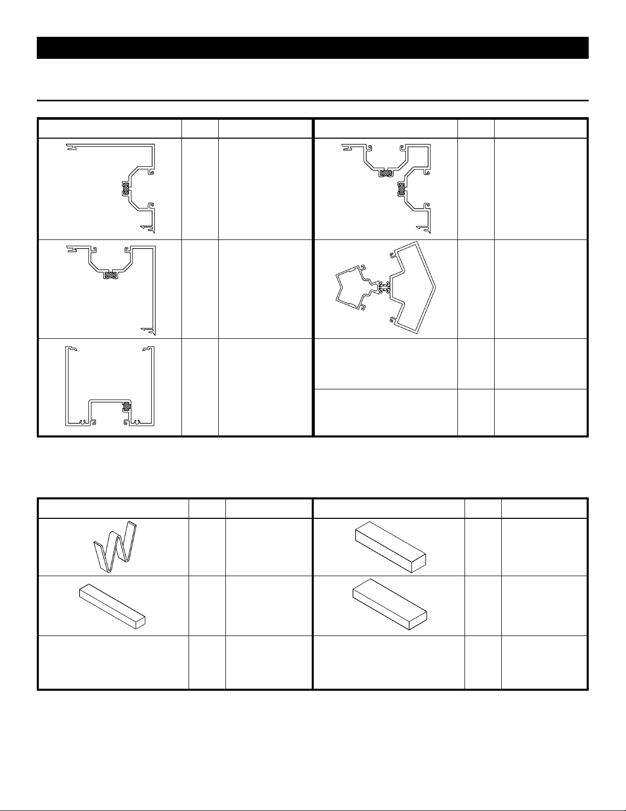
Section 2. Parts Identification
Horizontal Parts (cont.)
Profile Part # Description
90⁰ Corner Mullion Half
9299
Fits w/ 9297, 9300,
& 9305
Also Is Self-Mating
90⁰ Corner Mullion Half
9300
Fits w/ 9297, 9299,
& 9300
Also Is Self-Mating
9327
4” x 4 1/2” Head
or Horizontal
Profile Part # Description
90⁰ Corner Mullion Half
9305
2G56/
2G57
Fits w/ 9299, 9305,
& 9300
Also Is Self-Mating
2G56 Outside
2G57 inside
135⁰ Fixed Mullion
Setting and Anti-Walk Blocks
Profile Part # Description
HN52
HEP1
1/2” Anti-Walk
Block
Setting Block Pkg.
@ Bead-Down
Intermediate
Horizontal
EFCO 2013 Page 5
Profile Part # Description
Setting Block Pkg.
HN63
H157
@ Bead-Up
Intermediate
Horizontal
Setting Block Pkg.
@21S2 Sill
Page 6
Series 403X Storefront Installation Instructions
Section 2. Parts Identification
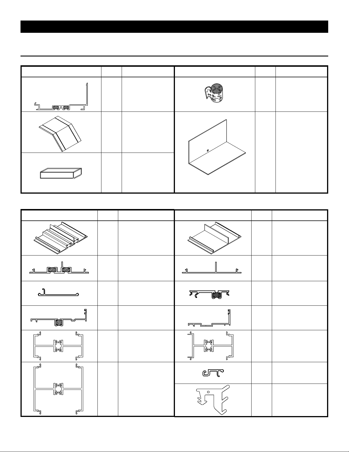
Sill and End-Dam Parts
Profile Part # Description
Profile Part # Description
21T1
HDW1
High Performance Sill
Flashing
Water Deflector @
Intermediate Horizontal
WM01
KO46
HCW6
Weep Baffle used
@ Sill
Bond Breaker Tape
4” X .062”
Used @ Sill Splices
Sill Flashing End-Dam
Package Use w/ 21T1
Sill Flashing
Misc. Parts
Profile Part # Description
F728
3” Perimeter
Adaptor Clip
Profile Part # Description
F729
3” Lightweight Vinyl
Perimeter
Adaptor Clip
21S4
LC55
9938
Stock Length
Perimeter
Adaptor Clip
Vinyl Pocket Filler @
Glass Pockets @
Perimeter
Shadow line
Window Adaptor Equal
Leg Use W104
Weathering
1G69
Horizontal / Vertical Stack
Adaptor 2” Sightline
1G15
Horizontal / Vertical Stack
Adaptor 4” Sightline
LC57
9351
8643
Stock Length Lightweight
Vinyl Perimeter
Adaptor Clip
Snap-In Pocket
Filler for 1”
Glazing Pocket
System II Window
Adaptor Equal Leg
1G68
21T8
Horizontal / Vertical
Stack Adaptor
2” Sightline w/ Reveal
Glazing Adaptor for 1/4”
Glass In 1” Glazing Pock-
et
W166
Glazing Gasket for
Oversized Glass 1 1/16”
Infill @ 1” Glazing Pocket
EFCO 2013 Page 6
Page 7
Series 403X Storefront Installation Instructions
Section 2. Parts Identification
Misc. Parts (cont.)
Profile Part # Description
WQ02
Optional
Weather Seal @
Sub-Frames
W104
STB9
F727
Weather Seal Gasket for
Expansion Mullions
Horizontal to Shear Block
Screw #12-11 x 1/2”
PL-RH-SMS 18-8 “A”
3” Rod for
Horizontal Dead Load
Support @ Int. Verticals
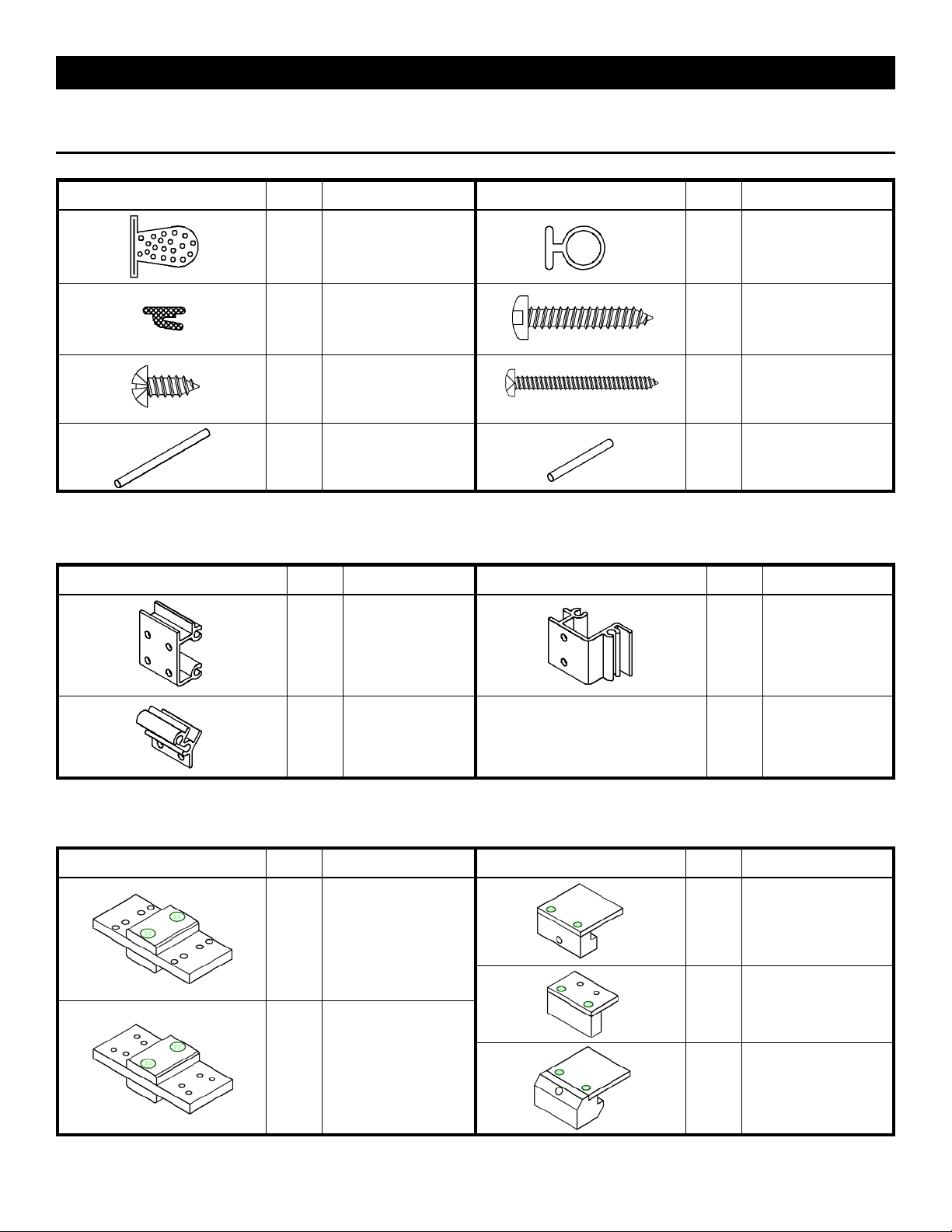
Shear Blocks
Profile Part # Description
KO48
Shear Block Pkg.
for Tubular
Horizontals
Profile Part # Description
WA04
SPL3
STB5
F726
Standard Weather Seal
@ Sub-Frames
Frame Spline Attachment
Screw #12-11 x 1 1/4”
SQ-PH-SMS 18-8 “A”
Shear Block
Attachment Screw
#12-11 x1-5/8” PL PH-
SMS 18-8 “A”
2” Rod for
Horizontal Dead Load
Support @ Perimeter
Verticals
Profile Part # Description
Shear Block Pkg.
for Open Back
Horizontals
KO49
KO47
Shear Block Pkg. for
21S2
Shear Blocks & Drill Fixtures
Profile Part # Description
Screw Spline Drill Fixture
DJ50
for
Vertical
Fabrication
DJ46
Shear Block Drill Fixture
for
Vertical
Fabrication
EFCO 2013 Page 7
Profile Part # Description
DJ49
DJ48
DJ47
Shear Block Drill Fixture
Support Pin Drill Fixture
Shear Block Drill Fixture
for
Horizontals
Dead Load
for
Horizontal 21S2
Page 8
Series 403X Storefront Installation Instructions
Section 3A. Screw Spline Fabrication
The screw spline system is a fabrication and erection method that permits the preassembly of single units in the
shop or at the job site. These units are then erected by mating the male mullion of one unit to its counterpart female
mullion of the adjoining unit.
Notes:
1. When an entrance is required, shear block joinery must be used to attach the side lite horizontals.
2. Due to the screw tensions required for correct installation, it will be necessary to ‘wax’ the frame assembly screws to
prevent galling and breaking.
Fabrication Steps:
1. Measure the opening to determine the cut lengths of the frame components.
Allow a minimum 1/4” clearance at head and jambs and 3/4” clearance at the sill for shims and caulking.
Allow extra clearances, if necessary, to accommodate building tolerances and building movement.
2. Cut the vertical to frame size.
Verticals must run through.
If the opening has an entrance, see the appropriate frame and door fabrication installation sheets.
Door jambs run to the floor and are cut longer than other verticals.
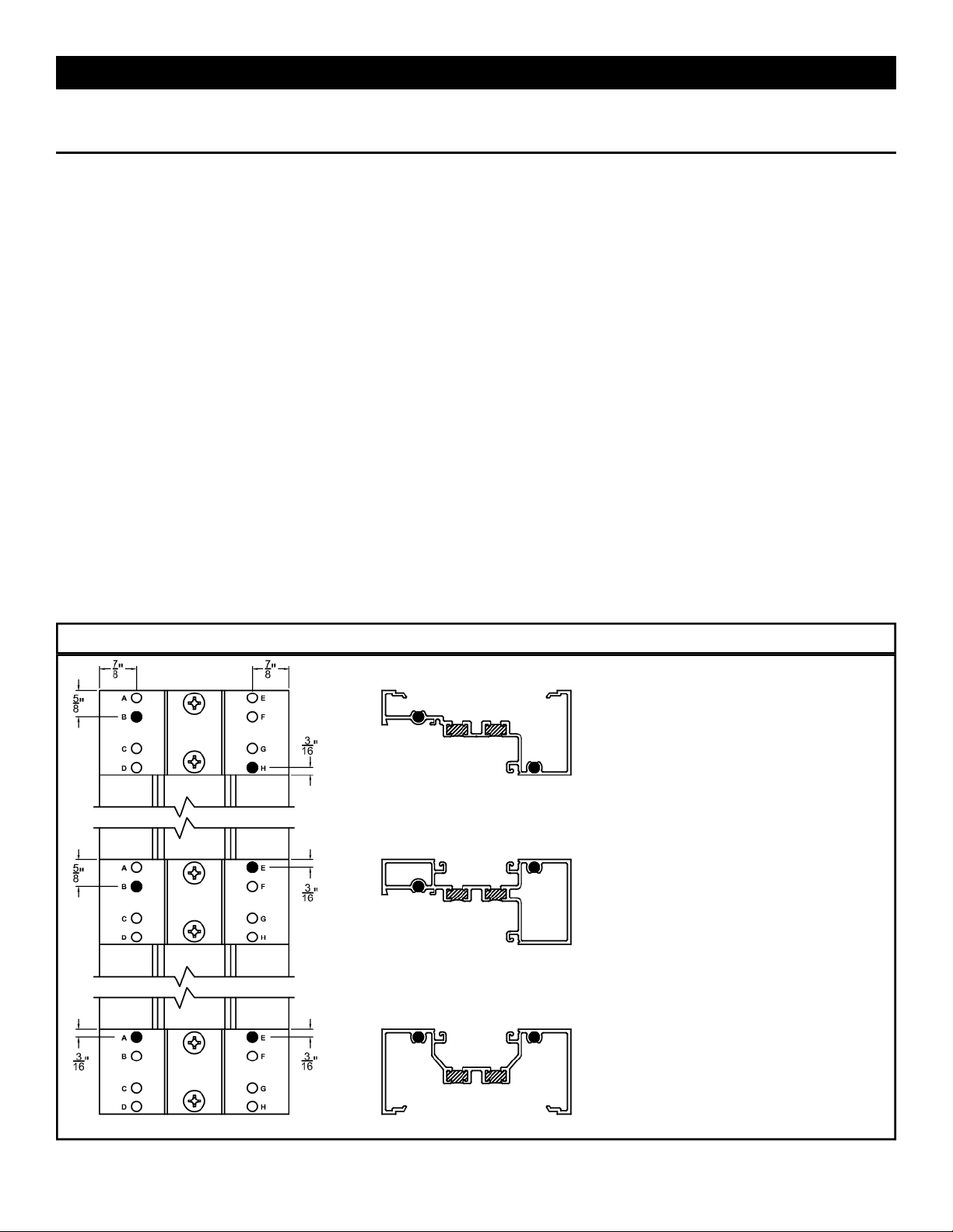
3. Drill holes for assembly screws on vertical members per one of the following methods.
Drill jigs are available. (See Page #7)
Layout holes per figures #1,2, or 3 and drill.
Use punch press with appropriate die set.
4. Cut horizontal members to day lite openings. (Between vertical members) Also cut the horizontal glass stops to day
lite opening minus 1/32”. (DLO - 1/32”)
Drilling Templates
Outside Glazed Bead-
Down
Screw Spline Verticals
Left Hand Shown, Right
Hand Opposite
Use Drill Jig #DJ50
Use a .230” dia. No. 1 drill
bit at darkened holes only.
Fig. #1
EFCO 2013 Page 8
Page 9
Series 403X Storefront Installation Instructions
Section 3A. Screw Spline Fabrication (cont.)
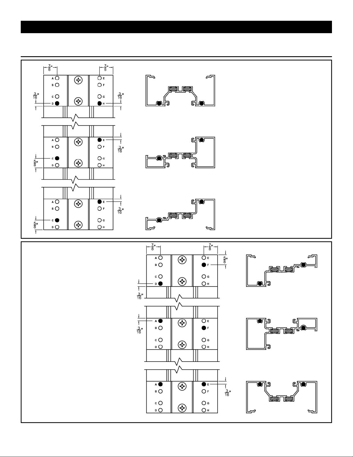
Left Hand Shown, Right Hand
Use a .230” dia. No. 1 drill bit
Outside Glazed Bead-Up
Screw Spline Verticals
Opposite
Use Drill Jig #DJ50
at darkened holes only.
Inside Glazed
Screw Spline Verticals
Left Hand Shown, Right Hand
Opposite
Use Drill Jig #DJ50
Use a .230” dia. No. 1 drill bit
at darkened holes only.
Fig. #2
Fig. #3
EFCO 2013 Page 9
Page 10

Series 403X Storefront Installation Instructions
Section 3B. Shear Block Fabrication
The shear block system is a fabrication and erection method that permits the preassembly of single units in the
shop or at the job site. These units are joined with shear blocks and then installed as a n assembled u nit in the opening
on top of any sill flashing that is used.
Fabrication Steps:
1. Measure the opening to determine the cut lengths of the frame components.
Allow a minimum 1/4” clearance at head and jambs and 3/4” clearance at the sill for shims and caulking.
Allow extra clearances, if necessary, to accommodate building tolerances and building movement.
2. Cut the vertical to frame size.
Verticals must run through.
If the opening has an entrance, see the appropriate frame and door fabrication installation sheets.
Door jambs run to the floor and are cut longer than other verticals.
3. Cut horizontal members to day lite openings. (Between vertical members)
4. Cut the horizontal glass stops to day lite opening minus 1/32”. (DLO - 1/32”)
5. Drill holes for shear block screws on vertical members and prepare attachment holes on horizontal members per one
of the following methods.
Drill jigs are available. (See Page #7)
Layout holes per details #4,5,6 and drill.
Use punch press with appropriate die set.
Drilling Patterns
Outside Glazed Bead-Down
Shear Block Verticals
Left Hand Shown, Right Hand
Opposite
Use Drill Jig #DJ46
Use a .180” dia. No. 15 drill bit at
darkened holes only.
Fig. #4
EFCO 2013 Page 10
Page 11

Series 403X Storefront Installation Instructions
Section 3B. Shear Block Fabrication (cont.)
Left Hand Shown, Right Hand
Use a .180” dia. No. 15 drill bit at
Outside Glazed Bead-Up
Shear Block Verticals
Opposite
Use Drill Jig #DJ46
darkened holes only.
Inside Glazed
Shear Block Verticals
Left Hand Shown, Right Hand
Opposite
Use Drill Jig #DJ46
Use a .180” dia. No. 15 drill bit at
darkened holes only.
Fig. #5
Fig. #6
EFCO 2013 Page 11
Page 12

Series 403X Storefront Installation Instructions
Section 3B. Shear Block Fabrication (cont.)
DJ49
Shear Block Horizontals
21S5 Shown, also for open
back and tubular intermediate
horizontals.
Use Drill Fixture #DJ49
placed at each end of
horizontal as shown.
Use a .230” dia. No. 1 drill bit
for each hole.
DJ47
Fig. #7
21S5
F722
DJ47
F722
(a) (b)
F722
F722
DJ49
21S5
F724
21S2 Shear Block
Horizontals
Use Drill Fixture
#DJ47 placed at
each end of
horizontal as
shown.
Drill one side as in
Fig. 8a then flip
drill fixture to
opposite side as in
Fig. 8b.
Use a .230” dia.
No. 1 drill bit for
each hole.
Fig. #8
Vertical Dead Load Shear Pins
Use Drill Fixture #DJ48 placed on vertical as shown below.
Left Hands Shown, Right Hands Opposite
Use a .189” dia. No. 12 drill bit at darkened hole only.
DJ48
DJ48
Fig. #9
EFCO 2013 Page 12
DJ48
Page 13

Series 403X Storefront Installation Instructions
Section 3C. Corner Fabrication
Notes:
1. 90⁰ Corners are designed for use with the shear block or screw spl ine system.
2. Because of possible screw spline and corner snap interference, the 3 way corners must be shear block system only.
3. Do Not measure hole locations from locking corners.
4. All 4 1/2” vertical corners can be mated together or with any other corner regardless of system considerations.
5. The 90⁰ corner halves may be snapped together and used as a one piece vertical mullion.
6. Refer to current available extrusions for all possible combinations.
Screw Spline System Fabrication Steps:
1. Follow steps 1-3 in Section 3A for cut lengths and hole preparations.
2. Follow standard unit construction method.
Shear Block System Fabrication Steps:
1. Follow steps 1, 2, and 5 in Section 3B for cut lengths and hole preparations.
2. Follow standard unit construction.
Standard Corner Fabrication Combinations
9300
8698
9296
9305
8698
9296
9305
*Shear Block Only*
9299 9297
9299
8697
9224
9300
*Shear Block Only*
8697
9224
9299
8697
9224
9300
9300
Fig. #10
Note:
CORNERS MUST BE SLID APART
EFCO 2013 Page 13
Page 14

Series 403X Storefront Installation Instructions
Section 3C. Corner Fabrication (cont.)
Fixed, Inside, Outside, and 135⁰ Corners
Shear block application only.
Follow steps 1, 2, and 5 in Section 3B for cut lengths and hole preparations.
#8558
#2G56 Inside Corner
2G57 Outside Corner
** Reverse Mullions For Inside Corners **
Fig. #11
Variable Degree Corners
Screw spline construction ONLY.
The exterior exposure of the variable mullion will be dependent upon the angle of splay and will be job specific.
Screw Spline System Fabrication Steps:
1. Follow steps 1-3 in Section 3A for cut lengths and hole preparations.
W104
9317 9316
W104
W104
9318 9316
W104
Variable 15⁰ to 30⁰ Corner Variable 0⁰ to 15⁰ Corner
W104
9316 9319
W104
Fixed 23⁰ Corner
Fig. #12
EFCO 2013 Page 14
Page 15

Series 403X Storefront Installation Instructions
Section 3D. Expansion Mullions
Expansion mullions are required in elevations that are over 20’ - 25’ wide and can be used with both screw
spline and shear block systems.
Do Not use expansion mullions at entrance jambs. Locate the expansion mullion at the next vertical mullion over so
that the distance between expansion mullions is never more than 25’-0”.
Screw Spline System Fabrication Steps:
1. Follow steps 1-3 in Section 3A for cut lengths and hole preparations.
2. Follow standard unit construction method.
Shear Block System Fabrication Steps:
1. Follow steps 1, 2, and 5 in Section 3B for cut lengths and hole preparations.
2. Follow standard unit construction.
Note:
W104
21S8 21S7
Expansion Joint gap must be
maintained before anchoring unit.
W104
Fig. #13
EFCO 2013 Page 15
Page 16

Series 403X Storefront Installation Instructions
Section 3E. Steel Reinforcing
Fabrication Steps:
Cut the steel reinforcing to mullion length minus 3” and set flush with the bottom of the vertical.
Paint the cut ends to prevent rust.
Insert the steel into the mullion, then drill through the deep pocket of the mullion and the steel reinforcing at 16” on-
center - maximum spacing.
Tap the hole in the steel to accept proper machine screw for that mullion and steel reinforcing combination.
Drill a clear hole in the mullion with a .221” (#2) drill bit.
Install the steel with the appropriate screw. If it is a flat head screw it does not countersink into the mullion.
Standard Steel reinforcing Combinations
21S7 / 21S8
Expansion Mullion
21S7 Male
Expansion Mullion
21S8 Female
Expansion Mullion
M100 #12-24 x 3/4”
PL FH MS 18-8 UC
L101 Steel
Reinforcing
21T3 / 5G44 Vertical
Mullion
21T3 Open Back
Jamb
5G44 Open Back
Adaptor
MS01 #12-24 x 1/2”
PL PH MS 18-8
L100 Steel
Reinforcing
Fig. #14
EFCO 2013 Page 16
Page 17

Series 403X Storefront Installation Instructions
Section 3F. Unit Assembly - Screw Spline
Assembly Steps:
Butter the ends of all horizontals and fill vertical glazing vinyl pockets with butyl type sealant as represented by the
shaded areas in Fig. #15.
(Place sealant as shown unless ladder to be installed in opening immediately, then coat complete end of
horizontal.)
Wax type lubricant may be required at assembly fasteners.
Screw complete system together as shown in Fig. #15.
Clean off all excess butyl sealant after assembled.
Note:
SPL3
SPL3
Inside Glazed Assembly shown, Outside Glazed, expansion
mullion, and 4 1/2” horizontal assembly systems similar.
Sealant
SPL3
Sealant
SPL3
SPL3
Exterior Face
SPL3
Fig. #15
EFCO 2013 Page 17
Page 18

Series 403X Storefront Installation Instructions
Section 3F. Unit Assembly - Shear Block
Assembly Steps:
Butter the ends of all horizontals and fill vertical glazing vinyl pockets with butyl type sealant as represented by the
shaded areas in Fig. #16.
Wax type lubricant may be required at assembly fasteners and dead load pins.
Attach all shear block to verticals with fasteners provided.
Insert 2” dead load pins into jambs and expansion mullions and 3” dead load pins in all other vertical mem bers as
indicated.
Screw complete system together putting screw through horizontals into shear blocks.
Clean off all excess butyl sealant after assembled.
Note:
Inside Glazed Assembly shown, Outside Glazed, expansion
mullion, and 4 1/2” horizontal assembly systems similar.
Dead Load Pin
Sealant
Dead Load Pins
Shear Blocks
Exterior Face
Note:
All shear block packages come with
required fasteners.
Fig. #16
EFCO 2013 Page 18
Page 19

Series 403X Storefront Installation Instructions
Section 4A. Door Frame Installation
Notes:
If NO door frame is required, proceed to Section 4B.
If a door frame is required, the frame must be installed first. All subsequent ladders must be
installed from the door frame out.
Door frame jambs do not set on sill flashing. Door jambs must run through to the floor condition.
INSTALL 1ST
Installation Notes:
Correctly locate and install the door
frame into the opening as specified on
the shop drawings or architectural
drawings.
End dams are not required at the door
frame end of a sill flashing.
The sill flashing should butt up tight to
the door frame.
See Fig. #18 for sill flashing to door
frame sealant requirements.
Sill Flashing
Fig. #18
2" 2"
SUBFRAME CLEARANCE HOLE =
[DOOR OPENING WIDTH + 4"]
Fig. #17
Installation Notes:
Before installing the sill
flashing, apply a bead of
silicone style sealant to the end
of the sill flashing.
After Installation, tool excess
sealant into the joint where sill
flashing and door frame meet.
At glazing pockets build-up
silicone sealant in pocket to the
tallest point of the sill flashing.
Tool the silicone sealant so a
watertight seal is made, and so
that water will be directed out of
the glazing pocket and into the
sill flashing.
See Fig. #18 for sill flashing to
door frame sealant
requirements.
EFCO 2013 Page 19
Page 20

Series 403X Storefront Installation Instructions
Section 4B. Sill Flashing Fabrication
Fabrication Steps:
1. Cut Length - Measure the rough opening width. Subtract a 1/4” per sill flashing end for the thickness of the water
dam and the fastener head height from the rough opening.
With End Dams: CUT LENGTH = ROUGH OPENING - 1/4” x (# of ends with end dam )
Without End Dams: CUT LENGTH = ROUGH OPENING
2. Weep Holes - Drill a min. 5/16” diameter holes in the sill flashing 6” from each end and at no more than 42” apart.
(Fig. #19)
3. Weep Baffles - Take (1) HCW6 baffle and cut in half to dimensions in Fig. #19. Apply Sealant along bottom and
locate them over the weep holes as shown below.
4. End Dam Installation - Attach the sill flashing with 1 SPZ1 fastener per end dam. Apply a bead of silicone sealant to
the end of the sill flashing prior to attaching the end dam. Tool the sealant at the interior joint of the end dam (see
Fig. 20) to ensure a good watertight seal.
5. Sill Flashing without End Dams - Install sill flashing tight to the condition and then proceed to seal joint between sill
flashing and condition. To ensure a watertight seal use silicone style sealant and tool seal similar to Fig. #20 below.
HCW6
KO46
End Dam
Sealant
21T1 Sill Flashing
Weep Baffle
5/16” Dia. Weeps
Fig. #19
Sealant
Sealant
21T1 Sill Flashing
SPZ1
Fig. #20
EFCO 2013 Page 20
Page 21

Series 403X Storefront Installation Instructions
Section 4B. Sill Flashing Installation
Installation Steps:
1. Chalk Line - Before installing the sill flashing, measure the distance from the exterior of the condition to the desired
location of the exterior of the sill flashing. Do this at both ends of the opening. If the opening is too wide for just two
marks, measure every 15 feet. Snap a chalk line between the marks to align sill flashing.
2. Sealant Bed - Apply a silicone style of sealant to the sill flashing as shown in Fig. #21. Place the sill flashing into the
rough opening, and rotate the exterior face down into position also shown in Fig. #21. Apply enough sealan t to
ensure a complete seal.
3. Sill Flashing Anchoring - At a minimum, anchor at 6” from each jamb and corner and 16” on center.
4. Sill Flashing Anchor Seal - Sill flashing anchors must be sealed with a silicone type sealant. To ensure a proper
seal, tool the sealant onto the fastener and surrounding metal. This procedure should immediately follow an chor
installation so it is not forgotten. (See Fig. #22)
5. Sill Flashing Perimeter Seal - The interior of the sill flashing should be sealed with a silicone type sealant. Apply the
sealant and tool to ensure a proper seal. Clean off excess sealant. (See Fig. #22)
Notes:
These recommendations are for general erection procedures only.
For actual job conditions, see the details on the shop drawings.
For perimeter anchor type and spacing, refer to approved shop drawings or consult the project design professional.
Anchoring fasteners NOT supplied by EFCO
Direction of
Installation
Rotation
Setting Condition
21T1 Sill Flashing
Sealant
Fig. #21
21T1 Sill Flashing
Sealant
Sealant
Setting Condition
Fig. #22
EFCO 2013 Page 21
Page 22

Series 403X Storefront Installation Instructions
Section 4B. Sill Flashing Installation (cont.)
Splicing Steps:
1. Verify Sill Flashing - Check to see that sill flashing has been installed correctly. Sill flashing to be spliced every 20’
- 25’. Splice locations are to be located at least 6” from any vertical intermediate mullion.
2. Splice Gap - Make sure a 1/4” gap is left at every sill flashing splice location.
3. Splice Material - Use a silicone type sealant and a strip of WM01 bond breaker tape. Tape is to be 1 7/8” wide by
approximately 7 1/2” long.
4. Apply silicone to both sides of sill flashing ends and fill 1/4” void between sill flashing ends as shown in Fig. #23.
5. Center bond breaker tape splice over gap and set into sealant. Tool the sealant over the edges of the spli ce to
create a watertight seal.
6. Interior Gap - After the splice is installed, apply a cosmetic seal to the interior gap vertically up the splice. (Fig. #24)
Notes:
These recommendations are for general erection procedures only.
For actual job conditions, see the details on the shop drawings.
Follow these splice guidelines at sill flashing corners also with one modificatio n. No Gap.
Sealant
21T1 Sill Flashing
Apply sealant to
interior gap.
Fill 1/4” void
between sill
flashings.
Run sealant in 1/4” gap
between these two points.
Fig. #23
21T1 Sill Flashing
Bond Breaker Tape Splice
Sealant
Fig. #24
EFCO 2013 Page 22
Page 23

Series 403X Storefront Installation Instructions
Section 4C. Installation
Installation Steps:
1. Sealing the sill onto the Sill Flashing - Apply a silicone type sealant to the sill flashing as shown in Fig. #25(a)
before installing the first ladder of frame. Make sure enough sealant is applied to seal the areas shown. After all
frame ladders are installed clean all excess sealant from any exposed areas.
2. Installing Jamb side Ladder - Starting from a door frame if one is in the opening or jamb, place the ladder on the
sill flashing at an angle similar to what is shown in Fig. #25(b) below in its approximate location in the opening. Then
stand the ladder up into the condition. See Fig. #25(c) below for proper sill placement in flashing. Then slide the
ladder left or right into its final position.
DO NOT ALLOW SEALANT TO CURE BEFORE PLACING FRAME LADDER PIECE. FAILURE TO D O THIS WILL
RESULT IN IMPROPER ENGAGEMENT OF SILL INTO FLASHING.
21S2
21T1 Sill Flashing
Sealant
(a) (b) (c)
Fig. #25
Installation Steps:
3. Anchoring the Head - For D.L.O.’s (Day Light Opening) of 36” wide and smaller, locate one anchor 6” from each
jamb or vertical member only. For D.L.O.’s larger than 36” wide, an additional anchor located at the center point of
the D.L.O. is required. See Fig. #26 below.
4. Anchoring the Jambs - Anchors must be spaced 6” from the sill and head, and 24” ± 4” on-center along the rest of
the height making sure they do not interfere with the horizontal members. Similar to Fig. #26 below.
These are only recommendations for general erection procedures only . For actual job conditions, perimeter
anchor type and spacing, refer to approved shop drawings or consult the project design professional.
Notes:
Flat head screws only.
Seal ALL screw heads.
21S4
21S5
DO NOT fasten through the
thermal area.
Head condition is shown, jamb
condition is similar.
21S4 perimeter adaptor shown as
clips located at all fasteners.
Fig. #26
EFCO 2013 Page 23
Page 24

Series 403X Storefront Installation Instructions
Section 4C. Installation
5. Installing additional Frame Ladders - Make sure that the head and jamb have been shimmed and anchors have
been installed on the previous frame ladder. Apply sealant to the sill flashing as sown in Fig. #25(a) on page 23.
Place the additional ladder onto the sill flashing at approximately 1/4” from previously installed frame ladder and
follow steps 2 and 3 from page 23.
On screw spline construction make sure ladders snap together when pushed together.
On shear block construction make sure ladders are together and all shear block screws are installed.
6. Snapping Mullions Together - To snap the mullions together of two ladders, line up the mullion halves as shown in
Fig. #27(a) below. Place one clamp at the sill end of the mullion using wood blocks to protect the extrusions.
Tighten the C-clamp until snap begins to engage. Place additional C-clamps at mid-span and head of mullion.
Tighten all clamps until sightline as shown in Fig. #27(b & c) below is achieved. It may be necessary to move
clamps to ensure even engagement of snap. DO NOT try to hammer the mullion together as this will dent, bend,
scratch, or deform the mullion and may cause it to leak. After correctly snapping mullion together continue to install
ladder per step 3 on page 23.
5G44 / 21T3 21S7 / 21S8
(a) (b)
7. Perimeter Seal - After all units are installed
into the opening and anchored, begin
sealing process. Apply a generous amount
of silicone type sealant to the gap between
the frame and rough opening. Tool off all
excess sealant to ensure a proper seal and
to achieve an appropriate appearance.
C-clamp or similar
Wood Block
Fig. #27
Sealant
(c)
Sealant
Fig. #28
EFCO 2013 Page 24
Page 25

Series 403X Storefront Installation Instructions
Section 5A&B. W ater Deflector, Glass Pocket, & Glass Sizes
1. Water Deflector - Install the HWD1 at the ends of
the intermediate horizontals only. It is not
required at heads or sills. Use a silicone type
sealant and place some on the horizontal to
adhere the HWD1 onto the intermediate
horizontals. Ensure that the HWD1 fits flush with
the top of the intermediate horizontal glazing
pocket and smooth any excess silicone sealant so
water will flow easily over the water deflector.
As seen in Fig. #29 the deflector projects over
the corner of the adjacent glass unit below.
Allow the silicone to cure prior to glazing
glass.
2. Glazing Pocket Dimensions - The glazing
pockets on the 403X are 1 7/16” (1.438) wide and
will accept 1” glass, dry glazed. See Fig. #30.
3. Glass Size Formulas -
Horizontal: D.L.O. + 3/4”
Vertical: D.L.O. + 3/4”
See Fig.#31 Below
Typical Vertical
HDW1
Glass Unit Below
Fig. #29
Set into Sealant
Typical Horizontal
Fig. #30
Fig. #31
EFCO 2013 Page 25
Page 26

Series 403X Storefront Installation Instructions
Section 5C. Glazing
Glass Installation Steps
1. Glass Blocks - Place glass blocks at the standard 1/4 point locations. It may be necessary to place a small amount
of sealant on the bottom of the glass blocks to ensure they remain in their intended position. Refer to approved shop
drawings or consult project design professional to verify glass block locations.
2. Glazing Gasket - For inside glazed applications, install the exterior gasket prior to glass installation. For outside
glazed applications, install the interior gasket prior to glass installation.
Gasket Length = D.L.O. + 1/2%
Glazing Gasket Installation Steps
Seal 1” vertically and horizontally in the gasket races with silicone type sealant at all corners.
Install gasket by pushing the gasket into place at the ends. Move to the middle, then to 1/4 points and then
work the “waves” toward the ends. Do Not stretch the gasket or it will return to its original form, creating
gaps at the gasket intersections.
Vertical gasket runs thru and horizontal between. Seal the ends of the horizontal gaskets.
Clean off any excess sealant. Sealing races and gasket ends is required at the interior of the system
however, optional at exterior of the system.
See Fig. #32 below.
Typical
Jamb
Head
Sill
Sealant
Vertical
Note:
Vertical and jamb gaskets
installed first and run thru.
Horizontal pieces run
between.
Fig. #32
EFCO 2013 Page 26
Page 27

Series 403X Storefront Installation Instructions
Section 5C. Glazing
Glass Installation Steps (cont.)
3. Glass Installation - Make sure glass blocks are still in place. After getting glass based upon glass size formulas on
page 25 follow these steps:
A. Position the g lass on the appropriate side of the framing without the removable glass stop installed. Shift
the glass into the deep pocket to begin glass installation.
B. Swing the op posite glass edge around to align with the glazing pocket.
C. Slide the glass into the sh allow pocket and lower onto the setting blocks. Shift the glass unit until there is
equal glass bite on both sides of the D.L.O.. Ensure that the preinstalled gasket does not roll out of the
gasket race when moving the glass into place.
4. Glass Stop - Ensure that the glass stop hook track is clean and free of oil and dirt. Run a continuous bead of
silicone at area shown in Fig. #34(a). Before sealant cures place stop as seen in Fig. #34(b) and then rotate into
final position as seen in Fig. #34(c). Strong hand pressure or a slight tap with a mallet will ensure the glass stop
snap is engaged. This step is for both outside and inside glazed units.
Note:
This glass installation
procedure works for inside
or outside glazed units.
A
C
A
GLASS
B
GLASS
C
Fig. #33
(a) (b) (c)
Fig. #34
EFCO 2013 Page 27
Page 28

Series 403X Storefront Installation Instructions
Section 5C. Glazing
Glass Installation Steps (cont.)
5. Anti-Walk Block Installation - Make sure the
glass unit is pushed as far into shallow pocket as
possible. Stretch the anti-walk block out as shown
in Fig. #35. Slide the stretched out block between
the glass unit and glazing gasket track and push it
fully into the deep glass pocket at the midpoint of
the glass unit.
Use Anti-Walk Blocks At Deep Pockets Only
6. Second Glazing Gasket - Install the second
glazing gasket. Use the same instructions as was
described in step 2 for the initial glazing gasket
installation.
7. Deglazing with Anti-Walk Blocks - If necessary
follow these steps to deglaze a glass unit with antiwalk block.
Remove all interior and exterior glazing
gasket.
Push the glass fully to the shallow pocket
and either towards the exterior or interior of
the pocket. See Fig. #36.
Use a hooked tool to pull the anti-walk
block from the glass pocket.
Reverse the glass installation instructions
to remove the glass unit.
Anti-Walk Block
Fig. #35
Anti-Walk Block
GLASS
Remove Anti-Walk Block this
Fig. #36
EFCO 2013 Page 28
Direction
Page 29

Series 403X Storefront Installation Instructions
Section 5D. Window Adaptors and Glazing Adaptor
Equal Leg Shadowline Adaptor
For 1” glazing pockets only.
Horizontal Cut Length = D.L.O. - 1/16” (Horizontal pieces run thru)
Vertical Cut Length = D.L.O. - 11/32”
1/8” x 5/8” notch at back of vertical pieces to clear horizontal leg. (See Fig. #36)
Seal Joint Completely
For equal leg Shadowline windows: Window Dim. = D.L.O. - 9/16”
W104
SFQ2
Fig. #36
Equal Leg System II Adaptor
For 1/4” and 1” glazing pockets.
Horizontal Cut Length = D.L.O. -
1/16” (Horizontal pieces run thru)
Vertical Cut Length = D.L.O. - 5/16”
1/8” x 57/8” notch at back of vertical pieces
to clear horizontal leg. (See Fig. #37)
Seal Joint Completely
Attachment screw length determined by
pocket depth.
For equal leg System II windows: Window
Dim. = D.L.O. - 1/2”
Glazing Adaptor
Use extrusion #21T8 to reduce 1”
glazing pocket to a 1/4” glazing
pocket.
Fill glazing vinyl pocket 1” in each
direction at all four corners of
opening.
Place adaptor as seen in Fig. #38
(a). Using hand pressure or
tapping of a 6” long wood block
engage adaptor snap.
Push/tap until level with frame as
seen in Fig. #38(b).
Care must be taken not to bend
the pocket reducer as it is being
tapped into position.
Fig. #37
Fig. #38
W104
21T8
Sealant
Location at
ends
(b) (a)
EFCO 2013 Page 29
 Loading...