

Page 1

A
R-Series Remote
nnunciators and
Expanders Installation and
Operation Guide
P/N 3100969-EN • REV 05 • ISS 06MAY13
Page 2

r
Copyright © 2013 UTC Fire & Security Americas Corporation, Inc..
Trademarks and
patents
The R-Series Remote Annunciators and Expanders name and logo
are trademarks of UTC Fire & Security Americas Corporation, Inc..
Other trade names used in this document may be trademarks or
registered trademarks of the manufacturers or vendors of the
respective products.
Manufacture
Edwards, A Division of UTC Fire & Security
Americas Corporation, Inc.
8985 Town Center Parkway, Bradenton, FL 34202, USA
Version This document applies to R-Series Remote Annunciators and
Expanders version 2.0x.
FCC compliance Class A: This equipment has been tested and found to comply with
the limits for a Class A digital device, pursuant to part 15 of the FCC
Rules. These limits are designed to provide reasonable protection
against harmful interference when the equipment is operated in a
commercial environment. This equipment generates, uses, and can
radiate radio frequency energy and, if not installed and used in
accordance with the instruction manual, may cause harmful
interference to radio communications. Operation of this equipment in
a residential area is likely to cause harmful interference in which
case the user will be required to correct the interference at his own
expense.
2002/96/EC (WEEE directive): Products marked with this symbol
cannot be disposed of as unsorted municipal waste in the European
Union. For proper recycling, return this product to your local supplier
upon the purchase of equivalent new equipment, or dispose of it at
designated collection points. For more information see:
www.recyclethis.info.
Contact information For contact information, see www.edwardsutcfs.com.
Page 3

Content
Introduction to the R-Series#1
Installation terminals and controls#4
Installing annunciators and expanders#6
Wiring diagrams#8
Troubleshooting#10
Specifications#11
Operating the LCD models#12
Operating the LED models#15
Reading LCD displays#18
System Normal screen#18
Event Message screen#18
Details screen#19
Entering a password#20
Message priorities#21
R-Series Remote Annunciators and Expanders Installation and Operation Guide i
Page 4

ii R-Series Remote Annunciators and Expanders Installation and Operation Guide
Page 5
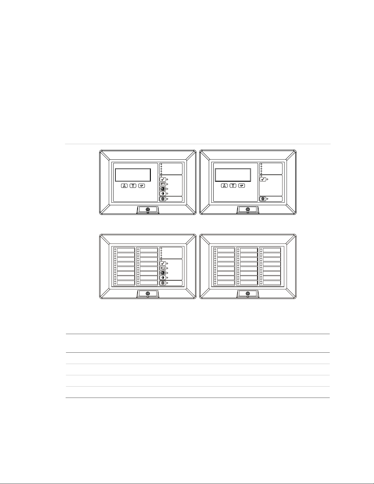
Introduction to the R-Series
The R-Series Remote Annunciators and Expanders provide remote annunciation
for fire and emergency alarm systems. The annunciators offer LCD or LED
annunciation, and can include common controls. The expander uses LEDs.
The R-Series includes three annunciator models and one expander model. One
or two expanders can be connected to any of the annunciator models. Figure 1
shows the four models in the R-Series. Table 1 lists the features of each model.
Table 2 is a complete list of all models and accessories in the series.
Figure 1: Models in the R-Series
Power
Alarm
Supervisory
Ground Fault
Trouble
Controls Enabled
Ack/Silence
Reset
Signal Silence
Drill
Lamp Test
RLCD-C
Power
Alarm
Supervisory
Ground Fault
Trouble
Controls Enabled
Ack/Silence
Reset
Signal Silence
Drill
Lamp Test
RLED-C
Table 1: Features of the models
Model LCD
Display
Zone
LEDs
Common
controls
RLCD
RLED24
Power
Alarm
Supervisory
Ground Fault
Trouble
Controls Enabled
Ack/Silence
Lamp Test
System
LEDs
Buzzer
RLCD, RLCD-R, RLCDF Yes No No Yes Yes
RLCD-C, RLCD-CR, RLCD-CF Yes No Yes Yes Yes
RLED-C, RLED-CR, RLED-CF No 16 pairs Yes Yes Yes
RLED24, RLED24R No 24 pairs No No No
The annunciators and expanders can be mounted on a standard 4 in. square
electrical box, using the included mounting ring. They can also be surface
mounted in locking steel enclosures.
R-Series Remote Annunciators and Expanders Installation and Operation Guide 1
Page 6

The annunciators communicate with the FACP on the RS-485 data riser. This
can be configured for Class A or Class B communication. The annunciators do
not provide ground fault isolation.
The annunciators are stand-alone units that can be powered by the FACP or by
an approved power supply.
Models with common controls can use a separate, remote key switch to enable
or disable the common controls.
Table 2: R-Series models and accessories
Model number Description
RLCD Remote Annunciator: LCD text annunciator without common controls.
English.
RLCD-R Remote Annunciator: LCD text annunciator without common controls.
English. Red.
RLCDF Remote Annunciator: LCD text annunciator without common controls.
French.
RLCD-C Remote Annunciator: LCD text annunciator with common controls.
English.
RLCD-CR Remote Annunciator: LCD text annunciator with common controls.
English. Red.
RLCD-CF Remote Annunciator: LCD text annunciator with common controls.
French.
RLED-C Remote Annunciator: 16-pair LED zone annunciator with common
controls. English.
RLED-CR Remote Annunciator: 16-pair LED zone annunciator with common
controls. English. Red.
RLED-CF Remote Annunciator: 16-pair LED zone annunciator with common
controls. French.
RLED24 Remote Expander: 24-pair LED zone expander with expander cable and
zone card insert.
RLED24R Remote Expander: 24-pair LED zone expander with expander cable and
zone card insert. Red.
RA-ENC1 One-position enclosure for Remote Annunciator.
RA-ENC2 Two-position enclosure for Remote Annunciator and one Remote
Expander, including one interconnection cable.
RA-ENC3 Three-position enclosure for Remote Annunciator and two Remote
Expanders, including two interconnection cables.
RKEY Remote key switch on plate for enabling or disabling common controls
(Lock/Unlock).
RA-LED16ZC Zone card insert for RLED-C, RLED-CR, and RLED-CF.
RA-LED24ZC Zone card insert for RLED24, RLED24R.
2 R-Series Remote Annunciators and Expanders Installation and Operation Guide
Page 7

Part number Description
27193-16 Electrical box, surface mount, white, single-gang.
7300073 24-inch expander cable assembly, includes cable and hardware.
7120313-01 12-inch expander cable (cable only).
7120313-02 24-inch expander cable (cable only).
R-Series Remote Annunciators and Expanders Installation and Operation Guide 3
Page 8
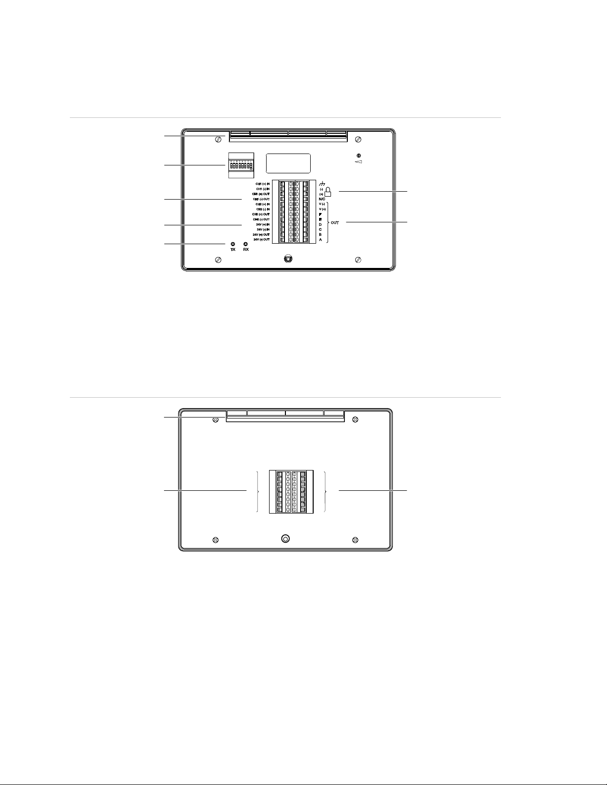
)(7)
Installation terminals and controls
Figure 2: Annunciator rear view showing terminals and controls
(1)
(2)
(3)
(4)
(5)
(1) Mounting slot
(2) DIP switch
(3) Annunciator bus IN/OUT terminals
(4) Power riser IN/OUT terminals
(5) Transmit and receive communication LEDs
(6) Remote key switch terminals
(7) Expander cable terminals
Figure 3: Expander rear view showing terminals
(1)
V (-)
V (+)
F
(2) (3)
E
IN
D
C
B
A
(6
V (-)
V (+)
F
E
OUT
D
C
B
A
(1) Mounting slot
(2) Expander cable IN terminals
(3) Expander cable OUT terminals
4 R-Series Remote Annunciators and Expanders Installation and Operation Guide
Page 9

Table 3: DIP switch settings
Switch Description
S1 to S5 Annunciator address.
The annunciator address (in binary). The factory setting is for address 2.
See Table 4 for examples. Possible values: 1 to 31.
S6 Baud rate.
OFF = 9600 baud (factory default setting)
ON = All other baud rates
S7 Annunciator circuit type.
OFF = Circuit supports Class B and Redundant Class B wiring
ON = Circuit supports Class B and Class A wiring
S8 Not used.
Table 4: Examples of DIP switch address settings
Address Setting Address Setting
1
2
3
4
5
ON
12 34 5678
ON
12 34 5678
ON
12 34 5678
ON
12 34 5678
ON
12 34 5678
6
7
8
16
31
ON
12 34 5678
ON
12 34 5678
ON
12 34 5678
ON
12 34 5678
ON
12 34 5678
R-Series Remote Annunciators and Expanders Installation and Operation Guide 5
Page 10

Installing annunciators and expanders
For correct operation, the annunciator must be configured with a unique address,
must have the correct baud rate setting, and must be in communication with the
FACP.
If you are installing a Remote Annunciator and Remote Expanders into RA-ENC2
or RA-ENC3 enclosures, you must install the expanders first. Refer to the
installation sheets for the enclosures for the correct sequence of steps.
If you are installing Remote Annunciators and Remote Expanders using separate
electrical boxes, the wire runs between the boxes must be enclosed in conduit.
If you are installing a remote key switch, the switch must be located within the
enclosure or within 3 ft. (0.9 m) of the enclosure with the cabling installed in
conduit or equivalent protection against mechanical injury.
To install an annunciator:
1. Secure the mounting ring to the electrical box, as shown in Figure 4.
2. Use the DIP switch to set the correct address and baud rate. See Table 3 on
page 5 for DIP switch settings.
3. Connect the control panel annunciator circuit to the appropriate annunciator
terminals. See Figure 5, Figure 6, Figure 7, and Figure 8.
Tip: Leave enough wire to remove and position the annunciator when setting
the DIP switch.
4. Attach the expander cable to the annunciator, if applicable. See Figure 9.
5. Attach the remote key switch wiring to the annunciator, if applicable. See
Figure 8.
6. Tilt the annunciator up and slide the mounting slot onto the top flange of the
mounting ring, as shown in Figure 4.
7. Tilt the annunciator down and push the bottom of the annunciator over the
stud-nut.
8. Secure the bottom of the annunciator to the mounting ring using the captive
screw.
9. Cover the screw hole with the product label plate.
To install an expander:
1. Complete and insert the zone card (labeling sheet) into the expander.
2. Secure the mounting ring to the electrical box, as shown in Figure 4.
3. Connect the expander cable to the expander. Attach an expander cable for
interconnection to a second expander, if applicable. See Figure 9.
6 R-Series Remote Annunciators and Expanders Installation and Operation Guide
Page 11

)
4. Tilt the expander up and slide the mounting slot onto the top flange of the
mounting ring, as shown in Figure 4.
5. Tilt the expander down and push the bottom of the expander over the studnut.
6. Secure the bottom of the expander to the mounting ring using the captive
screw.
7. Cover the screw hole with the product label plate.
8. Repeat steps 1 through 7 for a second expander, if applicable.
Figure 4: Installing the mounting ring, annunciator, and expander
(3)
(2)
(1)
(1)
(5)
(4)
(6)
(5
(4)
(1) Mounting ring
(2) Annunciator
(3) Expander
R-Series Remote Annunciators and Expanders Installation and Operation Guide 7
(4) Electrical box
(5) RS-485 riser
(6) Expander cable
Page 12

A
R
_
Wiring diagrams
All wiring is supervised and power-limited, unless otherwise noted. For terminal
connections, refer to the documents listed on the control panel label.
Figure 5: Typical Class B wiring
Power
Alarm
AUX_POWER
RS-485_BUS_B /
Supervisory
Ground Fault
Trouble
Controls Enabled
Ack/Silence
Reset
Signal Silence
Drill
Lamp Test
ANN_CH1
Figure 6: Typical redundant Class B wiring
Power
Alarm
UX_POWE
ANN_CH1
Supervisory
Ground Fault
Trouble
Controls Enabled
Ack/Silence
Reset
Signal Silence
Drill
Lamp Test
ANN_CH2
Figure 7: Typical Class A wiring
Power
Alarm
AUX_POWER
RS-485_BUS_B
Supervisory
Ground Fault
Trouble
Controls Enabled
Ack/Silence
Reset
Signal Silence
Drill
Lamp Test
Power
Alarm
Supervisory
Ground Fault
Trouble
Controls Enabled
Ack/Silence
Reset
Signal Silence
Drill
Lamp Test
Power
Alarm
Supervisory
Ground Fault
Trouble
Controls Enabled
Ack/Silence
Reset
Signal Silence
Drill
Lamp Test
Power
Alarm
Supervisory
Ground Fault
Trouble
Controls Enable d
Ack/Silence
Reset
Signal Silence
Drill
Lamp Test
Power
Alarm
Supervisory
Ground Fault
Trouble
Controls Enabled
Ack/Silence
Reset
Signal Silence
Drill
Lamp Test
Power
Alarm
Supervisory
Ground Fault
Trouble
Controls Enabled
Ack/Silence
Reset
Signal Silence
Drill
Lamp Test
Power
Alarm
Supervisory
Ground Fault
Trouble
Controls Enabled
Ack/Silence
Reset
Signal Silence
Drill
Lamp Test
RS-485
BUS_A
8 R-Series Remote Annunciators and Expanders Installation and Operation Guide
Page 13

Y
Figure 8: Typical annunciator wiring
RKE
(5)
RLCD(-C) / RLED(-C)
EGND
LOCK(- )
LOCK(+)
V( )_OUT
V( )_OUT
F_OUT
E_OUT
D_OUT
C_OUT
B_OUT
A_OUT
(4)
(1)
(2)
(3)
Ch1( )_IN
Ch1( )_IN
Ch1( )_OUT
Ch1( )_OUT
Ch2( )_IN
Ch2( )_IN
Ch2( )_OUT
Ch2( )_OUT
24V( )_IN
24V( )_IN
24V( )_OUT
24V( )_OUT
(1) CH1_IN+/− from the control panel or previous annunciator. CH1_OUT+/− to the next
annunciator or to the control panel if the last annunciator on a Class A circuit.
(2) CH2_IN+/− from the control panel or previous annunciator. CH2_OUT+/− to the next
annunciator. Used only on redundant Class B circuits. See Figure 6 on page 8.
(3) Use the control panel power supply or a 24 VDC, continuous, regulated, power supply that is
UL/ULC Listed for fire protective signaling systems.
(4) To the expander. See Figure 9.
(5) The remote key switch wiring is not supervised. The key switch must be located within 3 ft.
(0.9 m) of the annunciator and installed in conduit, or equivalent protection against
mechanical injury.
A remote key switch is required on RLED-C remote annunciators.
Figure 9: Typical expander wiring
RLCD(-C) /
RLED(-C)
V( )_OUT
V( )_OUT
F_OUT
E_OUT
D_OUT
C_OUT
B_OUT
A_OUT
V( )_IN
V( )_IN
F_IN
E_IN
D_IN
C_IN
B_IN
A_IN
RLED24
V( )_OUT
F_OUT
E_OUT
D_OUT
C_OUT
B_OUT
A_OUT
V( )_INV( )_OUT
V( )_IN
F_IN
E_IN
D_IN
C_IN
B_IN
A_IN
RLED24
R-Series Remote Annunciators and Expanders Installation and Operation Guide 9
Page 14

Troubleshooting
When an R-Series annunciator is operating correctly, the Trouble LED follows
the panel’s Trouble LED. Annunciators with LCD displays show the same trouble
messages as the panel. See the topic “Reading LCD displays” on page 18 for
details about message displays.
The following table summarizes symptoms and solutions for common installation
and operation problems.
Table 5: R-Series troubleshooting
Problem Cause
Panel detail display: Annunciator 000
Communication Fault
Annunciator LCD and LEDs are
inoperative
Annunciator control switches don’t work Remote key switch is in the “locked” or disabled
Lamp test During a lamp test the annunciators with LCDs show
Communication wiring has an open fault
Communication wiring polarity is reversed
Annunciator has no power
Annunciator address DIP switches are set incorrectly
(on the annunciator shown in the panel message)
Annunciator network baud rate DIP switch is set
incorrectly (for normal operation use 9600 baud)
Annunciator bus type DIP switch is set incorrectly
(change S1-7 to the other position)
Annunciator has no power
position
Password entry may be required (see “Entering a
password“ on page 20)
the version of annunciator firmware currently loaded
10 R-Series Remote Annunciators and Expanders Installation and Operation Guide
Page 15

Specifications
Voltage 24 VDC, continuous. Do not use control panel
AUX power outputs that are interrupted when
the panel is reset. Supply must be UL/ULC
Listed for use with fire protective signaling
systems and have a rating designation of
Regulated 24 DC or Regulated 24 FWR.
Standby current
RLCD, RLCD-R, RLCDF
RLCD-C, RLCD-CR, RLCD-CF
RLED-C, RLED-CR, RLED-CF
RLED24, RLED24R
Alarm current
RLCD, RLCD-R, RLCDF
RLCD-C, RLCD-CR, RLCD-CF
RLED-C, RLED-CR, RLED-CF
RLED24, RLED24R
Annunciator circuit
Class/Style
Wire size
Type
Length
Baud rate
Remote key switch circuit 5 VDC at 1 mA, power-limited, unsupervised
Ground fault impedance 0 Ω
Power wiring 14 to 18 AWG (1.0 to 2.5 mm²)
Display area 4 lines of 20 characters each
Dimensions (H x W x D) 5-5/8 x 8-1/2 x 1-1/2 in. (14.3 x 21.4 x 3.8 cm)
98 mA
99 mA
28 mA
6 mA
113 mA
115 mA
62 mA
34 mA
Class B, Redundant Class B, or Class A
14 to 18 AWG (1.0 to 2.5 mm²)
Twisted pair, 6 twists per ft. min.
4,000 ft. (1,219 m), max.
9600 to 115200 baud
Mounting North American 4 in. square electrical box or
listed enclosure (see Table 2)
Operating environment
Temperature
Relative humidity
R-Series Remote Annunciators and Expanders Installation and Operation Guide 11
32 to 120°F (0 to 49°C)
0 to 93% noncondensing
Page 16

(3)
(4)
(5)
(6)
(7)
(8)
(9)
(3)
(4)
(5)
(9)
Operating the LCD models
Figure 10: Controls and indicators for: RLCD-C, RLCD-CR, RLCD-CF
Power
Alarm
Supervisory
Ground Fault
(1)
(2)
Troub le
Controls Enabled
Ack/Silence
Reset
Signal Silence
Drill
Lamp Test
(11)(12)(13)(14)(15)
(10)
Figure 11: Controls and indicators for: RLCD, RLCD-R, RLCDF
Power
Alarm
Supervisory
Ground Fault
(1)
(2)
Troub le
Controls Enabled
Ack/Silence
Lamp Test
(11)(12)(13)(14)(15)
(10)
12 R-Series Remote Annunciators and Expanders Installation and Operation Guide
Page 17

Table 6: Controls and indicators for the RLCD, RLCD-R, RLCDF, RLCD-C, RLCD-CR, and
RLCD-CF
No. Item Description
1 LCD display Displays system status, event messages, and event
message details.
2 Up cursor button Scrolls up through the messages in the event message
queue. Scrolls up through characters for password entry.
3 Down cursor button Scrolls down through the messages in the event message
queue. Scrolls down through characters for password entry.
4 Enter button Displays message details for the current message. Enters
the password character selected.
5 Lamp Test LED-button Green LED that indicates the annunciator is energized.
Turns on all LEDs and displays a test pattern on the LCD.
The test runs for ten seconds. The LED next to the button
indicates the lamp test is running.
6 Drill LED-button Turns on all audible and common alarm output devices and,
if configured, all visible devices. Pressing the button again
turns them back off. The LED next to the button indicates the
function is active. Requires a password to operate.
Note: You must press and hold the button for 2 seconds to
initiate a drill.
7 Signal Silence LED-
button
Turns off (silences) all active audible and common alarm
output devices and, if configured, all visible devices.
Pressing the button again turns them back on. The LED next
to the button indicates the function is active. Requires a
password or the enable controls key to operate.
8 Reset LED-button Restores the system to the normal state, provided that no
inputs are latched in the active state. The LED next to the
button indicates the reset function is active. Requires a
password or the enable controls key to operate.
9 Ack/Silence LED-button Silences the panel buzzer and acknowledges all current
events. The LED next to the button indicates the function is
active. Requires a password or the enable controls key to
operate.
10 Controls Enabled LED Blue LED that indicates the controls in that group are
enabled at the annunciator. Enabling the controls requires a
password or the enable controls key.
11 Trouble LED Yellow LED that indicates an active trouble state (flashing =
new trouble event, steady = all current trouble events have
been acknowledged).
12 Ground Fault LED Yellow LED that indicates a ground fault somewhere in the
system.
13 Supervisory LED Yellow LED that indicates an active supervisory state
(flashing = new supervisory event, steady = all current
supervisory events have been acknowledged).
R-Series Remote Annunciators and Expanders Installation and Operation Guide 13
Page 18

No. Item Description
14 Alarm LED Red LED that indicates an active alarm state (flashing = new
alarm event, steady = all current alarm events have been
acknowledged).
15 Power LED Green LED that indicates the annunciator is energized.
14 R-Series Remote Annunciators and Expanders Installation and Operation Guide
Page 19

(1)
(2)
(5)
(6)
(7)
(8)
(9)
(1)
(2)
Operating the LED models
Figure 12: Controls and indicators for: RLED-C, RLED-CR, RLED-CF
(11)(12)(13)(14)(15)
Power
(3)
(4)
Alarm
Supervisory
Ground Fault
Trouble
Controls Enabled
Ack/Silence
Reset
Signal Silence
Drill
Lamp Test
(10)
Figure 13: Controls and indicators for the RLED24 and RLED24R
(3)
(4)
R-Series Remote Annunciators and Expanders Installation and Operation Guide 15
Page 20

Table 7: Controls and indicators for the RLED-C, RLED-CR, RLED-CF, RLED24, and
RLED24R
No. Item Description
1 Zone description label Zone or device description.
2 Active LED Red LED that indicates the zone or device is in the alarm
state.
3 Trouble LED Yellow LED that indicates the zone or device is in the trouble
state.
4 Supervisory zones The last four zones can be configured as alarm or
supervisory. For these zones, the top LED is a red/yellow
bicolor LED. Red = alarm event. Yellow = supervisory or
monitor event.
5 Lamp Test LED-button Turns on all LEDs and displays a test pattern on the LCD.
The test runs for ten seconds. The LED next to the button
indicates the lamp test is running.
6 Drill LED-button Turns on all audible and common alarm output devices and,
if configured, all visible devices. Pressing the button again
turns them back off. The LED next to the button indicates the
function is active. Requires a password to operate.
Note: You must press and hold the button for 2 seconds to
initiate a drill.
7 Signal Silence LED-
button
Turns off (silences) all active audible and common alarm
output devices and, if configured, all visible devices.
Pressing the button again turns them back on. The LED next
to the button indicates the function is active. Requires a
password or the enable controls key to operate.
8 Reset LED-button Restores the system to the normal state, provided that no
inputs are latched in the active state. The LED next to the
button indicates the reset function is active. Requires a
password or the enable controls key to operate.
9 Ack/Silence LED-button Silences the panel buzzer and acknowledges all current
events. The LED next to the button indicates the function is
active. Requires a password or the enable controls key to
operate.
10 Controls Enabled LED Blue LED that indicates the controls in that group are
enabled at the annunciator. Enabling the controls requires a
password or the enable controls key.
11 Trouble LED Yellow LED that indicates an active trouble state (flashing =
new trouble event, steady = all current trouble events have
been acknowledged).
12 Ground Fault LED Yellow LED that indicates a ground fault somewhere in the
system.
13 Supervisory LED Yellow LED that indicates an active supervisory state
(flashing = new supervisory event, steady = all current
supervisory events have been acknowledged).
16 R-Series Remote Annunciators and Expanders Installation and Operation Guide
Page 21

No. Item Description
14 Alarm LED Red LED that indicates an active alarm state (flashing = new
alarm event, steady = all current alarm events have been
acknowledged).
15 Power LED Green LED that indicates the annunciator is energized.
R-Series Remote Annunciators and Expanders Installation and Operation Guide 17
Page 22

Reading LCD displays
In addition to the system status LEDs, two annunciator models include an LCD
display that can show the system status, event messages, or event message
details. The display can also be used to enter a password that enables the
common control buttons.
System Normal screen
The LCD display shows the System Normal screen when the control panel is in
the normal (quiescent) state.
HH:MM:SS MM/DD/YY
Your Building
System is Normal
(1) Time and date: The system time in 24-hour format and the system date in MM/DD/YY or
DD/MM/YY format, depending on the market place.
(2) Banner lines: Your facility name (if programmed) and the message “System is Normal.”
(1)
(2)
Event Message screen
The LCD display shows the Event Message screen when the control panel
enters the alarm, supervisory, monitor, trouble, disablement, or test state. Use
the Up and Down cursor buttons to scroll through the messages in the queue.
HH:MM:SS Annn Dnnn
NNN SSSSSSSSSS RRR
MESSAGE LINE 1 XXXXX
MESSAGE LINE 2 XXXXX
(1) Time and points: The system time in 24-hour format, the number of active points (Annn), and
the number of disabled points (Dnnn) currently in the system.
(1)
(2)
(3)
(2) Event status: The event number (NNN), the event type (SSSSSSSSSS), and the event status
(RRR). The event number is the position of the event in the queue. The event type is alarm,
supervisory, trouble, or monitor. The event status is “Act” for active, or “Rst” for restored.
(3) Event message: The first and second lines of the event message.
Example Event Message screen
13:47:00 A003 D000
001 ZONE ALARM ACT
East Wing Hallway
South Entrance
18 R-Series Remote Annunciators and Expanders Installation and Operation Guide
Page 23

Details screen
Pressing the Enter button while an event message is selected displays the
Details screen. The system displays this screen as long as you are pressing the
Enter button or using the Up and Down cursor buttons. The system returns to the
Event Message screen after approximately 20 seconds of inactivity. You can also
toggle between the Event Message and Details screens by pressing and
releasing the Enter button.
DETAILS
P:nn C:nn D:nnn
DEVICE MESSAGE LINE1
DEVICE MESSAGE LINE2
(1)
(2)
(3)
(1) Scrolling symbols: The symbols at the right of the screen title line show whether there are
more detail messages before or after the current message. Use the Up and Down cursor
buttons to scroll through the detail messages or devices in the zone. The up or down symbols
disappear when you reach the start or end of the list (or when there are no off-normal
devices).
(2) Device address: The panel (P), card (C), and device number (D) that constitute the complete
device address for the device generating the event message.
(3) Device message lines: If programmed, the device message for the device that generated the
event message. This is usually a location description.
The Details screen provides details about the zone or device that generated the
selected event message. If the selected event message is for a zone, the Details
screen shows which devices in the zone are active.
Example Details screen
DETAILS
P:01 C:01 D:001
East Wing Hallway
South Entrance
R-Series Remote Annunciators and Expanders Installation and Operation Guide 19
Page 24

)(2)(3)
Entering a password
When the Controls Enabled LED is off, you need to enter a password to enable
the controls. When you press any of the control buttons, the system displays the
Enter Password screen.
ENTER PASSWORD
?---
SCROLL=+/-NUMBER
ENTER =NEXT DIGIT
(1) Title line: This is constant text.
(2) Password: You use the Up and Down cursor buttons to scroll through the digits in each
position of the password. Each number appears on this line, but is masked as soon as you
press the Enter button.
(3) Instruction lines: These lines prompt you to press the Up and Down cursor buttons to select a
number, or the Enter button to select a number and move to the next position.
(1
To enter a password:
1. Press any of the control buttons.
The system displays the Enter Password screen, with the cursor in the first
position of the four-digit password field.
2. Press the Up or Down cursor button to scroll through the numbers until the
correct number appears.
3. Press the Enter button to enter that number and move to the next position.
When you press Enter, the system masks the number you just entered with
an asterisk.
4. Repeat steps 2 and 3 until you’ve entered all four digits of the password.
If you make a mistake, pressing Enter before filling all four positions cancels the
operation, and returns you to the System Normal screen. If you enter an invalid
password, the system displays an error message and returns you to the Enter
Password screen.
20 R-Series Remote Annunciators and Expanders Installation and Operation Guide
Page 25

Message priorities
Event messages are stored in a single list or queue. Within the queue they are
sorted into priority according to the event type and the order of event occurrence.
The priority of event types is shown in the following lists.
US market place
1. Alarm events
2. Supervisory events and Trouble events
3. Other (monitor) events
Canadian market place
1. Alarm events
2. Supervisory events
3. Trouble events
4. Other (monitor) events
European market place
1. Alarm events
2. Supervisory events
3. Trouble events
4. Other (monitor) events
R-Series Remote Annunciators and Expanders Installation and Operation Guide 21
Page 26

22 R-Series Remote Annunciators and Expanders Installation and Operation Guide
 Loading...