


FireShield
Technical Reference Manual
P/N 3100353 • Rev 3.0 • 12MAY03

DEVELOPED BY
Phone: (941) 739-4200
Copyright © 2002–2003
IMPORTANT INFORMATION
Limitation of liability
This product has been designed to meet the requirements of the standards listed in “Compliance statement” below. Installation in accordance with this manual, applicable codes, and the instructions of the Authority Having Jurisdiction is mandatory. The manufacturer shall not under any circumstances be liable for any incidental or consequential damages arising from loss of property or other damages or losses owing to the failure of products beyond the cost of repair or replacement of any defective products. The manufacturer reserves the right to make product improvements and change product specifications at any time.
While every precaution has been taken during the preparation of this manual to ensure the accuracy of its contents, the manufacturer assumes no responsibility for errors or omissions.
FCC warning
This equipment can generate and radiate radio frequency energy. If this equipment is not installed in accordance with this manual, it may cause interference to radio communications. This equipment has been tested and found to comply within the limits for Class A digital devices pursuant to Subpart B of Part 15 of the FCC Rules. These rules are designed to provide reasonable protection against such interference when this equipment is operated in a commercial environment. Operation of this equipment is likely to cause interference, in which case the user, at his own expense, will be required to take whatever measures may be required to correct the interference.
Compliance statement
FireShield, when properly installed, operates as a Local Protected Premises Fire Alarm System in accordance with the following standards:
•NFPA Standard 72, 1999 Edition
•NFPA 70 National Electrical Code
•Underwriters Laboratories Standard 864, 8th Edition
•Underwriters Laboratories of Canada Standard ULC S527-99
•Canadian Electrical Code Part I
•Standard for Installation of Fire Alarm Systems ULC S524
•Standard for the Inspection and Testing of Fire Alarm Systems ULC S536
FireShield also complies with Local Protective Signaling (type L) - manual (M), automatic (A), waterflow (WF), and sprinkler supervisory (SS) for:
•Coded (C) and non-coded signaling (NC)
•Remote Station (type RS) - with RPM or FSDACT
•Auxiliary (type A) - with CTM4.7 (this may include Local with Shunt type connection to Master Box - type LS)
•Central Station (Type CS) - with FSDACT
Content
Chapter 1 System overview and operation • 1.1
System overview • 1.1 Operations overview • 1.1 Controls and indicators • 1.1 Component descriptions • 1.3 Operating the panel • 1.4 FSDACT LCD messages • 1.7
Chapter 2 |
Installation • 2.1 |
|
Installation checklist • 2.1 |
|
Installing the cabinet • 2.1 |
|
Installing the Remote System Indicator • 2.2 |
|
Installing the Remote Zone Indicator • 2.3 |
|
Installing the Remote Relay Module • 2.5 |
|
Installing the Power Expander Transformer • 2.7 |
|
Installing the FSDACT • 2.8 |
|
Connecting an RPM module • 2.10 |
|
Connecting a CTM module • 2.11 |
|
Connecting an auxiliary power supply • 2.12 |
|
Installing the terminal shield • 2.12 |
Chapter 3 Programming • 3.1
Overview • 3.1
Using the factory default settings • 3.2 Using an FSDACT • 3.2
Custom programming the panel • 3.2 FSDACT programming • 3.8
Chapter 4 |
Maintenance • 4.1 |
|
Preventive maintenance • 4.1 |
Appendix A |
Calculations • A.1 |
|
Battery calculation worksheet • A.1 |
|
Notification appliance voltage drop |
|
calculation • A.3 |
|
Notification appliance circuit maximum wire |
|
length calculation • A.4 |
Appendix B |
Programming templates • B.1 |
|
Panel programming worksheet • B.1 |
|
FSDACT programming worksheet • B.2 |
Appendix C |
Jumper settings and wiring diagrams • C.1 |
Appendix D |
Panel specifications • D.1 |
Appendix E |
Default event codes • E.1 |
|
Default Contact ID event codes • E.1 |
|
Default (4/2) event codes • E.2 |
ZIndex • Z.1
FireShield Fire Alarm Control Panel Operating Instructions • 1
Chapter 1
System overview and operation
If the optional FSDACT is installed, the panel:
•Sends a record of the event to the FSDACT LCD and to the history log
•Uses the FSDACT to transmit event messages to a monitoring station as programmed
System overview
FireShield is available in three models: three-zone, five-zone, and ten-zone. Each model is similar except for the number of initiating device circuits (IDCs) and notification appliance circuits (NACs), as shown in the following table.
Model |
IDCs |
NACs |
FS302 (three-zone) |
3 |
2 |
|
|
|
FS502 (five-zone) |
5 |
2 |
|
|
|
FS1004 (ten-zone) |
10 |
4 |
Model numbers may have the following suffixes: G or R indicates gray or red enclosure, GD or RD indicates panel with FSDACT, GC indicates ULC panel with terminal shield, GF indicates a French ULC panel with terminal shield, and G-2 indicates 230 Vac input.
Each panel is configured for Class B operation. All models except for the three-zone can be easily converted to Class A by using two Class B circuits to make one Class A circuit.
FireShield has the following optional components:
•Remote System Indicator (FSRSI)
•Remote Zone Indicator (FSRZI-A)
•Remote Relay Module (FSRRM)
•Power Expander Transformer (XTR3A120, XTR3A230) (ten-zone only)
•DACT (Dialer)/Modem (FSDACT)
•City Tie Module (CTM4.7)
•Reverse Polarity Module (RPM)
•Battery Cabinet (BC-2)
Refer to Chapter 2 “Installation” for optional module details.
Operations overview
The panel operates in normal mode in the absence of any alarm, supervisory, trouble, or monitor events. In normal mode, the control panel monitors the system.
The panel operates in off-normal mode any time an event is introduced into the system. When this happens, the panel:
•Changes contact positions on appropriate common relays
•Activates alarm outputs (for alarm events only)
•Turns on the appropriate LEDs and the panel buzzer
•Executes the appropriate programmed output response for the input that signaled the event
•Communicates event information to appropriate optional components (FSRSI, FSRZI-A, CTM4.7, or RPM)
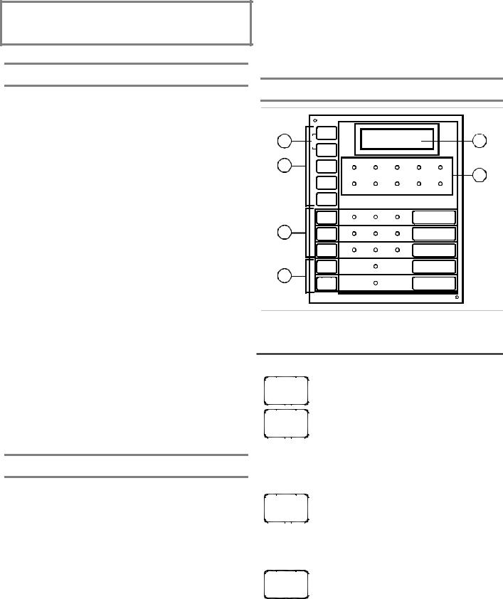
Controls and indicators
|
|
REMOTE |
|
|
|
|
|
|
1 |
TESTLAMP |
DISCON- |
|
|
|
|
|
6 |
NECT |
|
|
|
|
|
|||
|
|
|
|
|
|
|
|
|
|
|
WALK |
|
|
|
|
|
|
2 |
|
TEST |
|
|
|
|
|
|
|
RESET |
ALARM |
TROUBLE |
SUP |
POWER |
DISABLE |
|
|
|
|
|
|
|
|
|
|
|
|
|
SIGNAL |
ANNUN |
BATT |
GND |
WALK |
SIGNAL |
5 |
|
|
TROUBLE |
TROUBLE |
FAULT |
TEST |
SILENCED |
||
|
|
SILENCE |
|
|
|
|
|
|
|
|
& DRILL |
|
|
|
|
|
|
|
|
PANEL |
|
|
|
|
|
|
|
|
SILENCE |
|
|
|
|
|
|
|
|
|
ALARM |
TROUBLE |
SUP/MON |
|
|
|
|
|
DISABLE |
1 |
|
|
|
|
|
3 |
|
DISABLE |
2 |
|
|
|
|
|
|
|
DISABLE |
3 |
|
|
|
|
|
|
|
|
|
|
|
|
|
|
|
|
DISABLE |
NAC 1 |
|
|
|
|
|
|
|
|
|
|
|
|
|
|
4 |
|
DISABLE |
NAC 2 |
|
|
|
|
|
|
|
|
|
|
|
|
||
|
|
|
|
|
|
|
|
Front panel display
(1) Lamp test
Buttons |
|
|
|
|
|
|
Description |
|||
|
|
|
|
|
|
|
|
|
|
Press the Remote Disconnect and Walk Test |
|
|
|
|
|||||||
|
|
REMOTE |
|
|
|
|
|
|||
|
|
|
|
|||||||
|
|
DISCON- |
|
|
|
|
|
|
buttons simultaneously to initiate a panel |
|
|
|
|
NECT |
|
|
|
|
|
|
lamp test. This lets you verify proper |
|
|
|
|
|
||||||
|
|
|
|
|
|
|
|
|
|
operation of the LEDs on the panel and the |
|
|
|
|
|
||||||
|
|
|
|
|
|
|
|
|
||
|
|
|
|
|
|
|
|
|
||
|
|
WALK |
|
|
|
|
|
|
remote annunciators. |
|
|
|
|
TEST |
|
|
|
|
|
|
|
|
|
|
|
|||||||
|
|
|
|
|||||||
|
|
|||||||||
(2) Control buttons |
||||||||||
Button |
|
|
|
|
|
|
Description |
|||
|
|
|
|
|
|
|
|
|
|
Operating mode with FSDACT: Disables or |
|
|
|
|
|
|
|
|
|
||
|
|
REMOTE |
|
|
|
|
|
|
||
|
|
|
|
|
|
|
|
|||
|
|
DISCON- |
|
|
|
|
|
|
enables FSDACT. Has no effect on alarm |
|
|
|
|
NECT |
|
|
|
|
|
|
relay. |
|
|
|
|
|
|
|
|
|
||
|
|
|
|
|
|
|
|
|
|
Operating mode without FSDACT: Disables |
|
|
|
|
|
|
|
|
|
|
|
|
|
|
|
|
|
|
|
|
|
or enables the common alarm relay. |
|
|
|
|
|
|
|
|
|
|
Programming mode: Selects the next option. |
|
|
|
|
|
|
|
|
|
|
Operating mode: Places the panel in walk |
|
|
|
|
|
|
|
|
|
|
|
|
|
WALK |
|
|
|
|
|
|
||
|
|
|
|
|
|
|
|
test mode. The Walk Test LED is on when |
||
|
|
|
TEST |
|
|
|
|
|
|
the panel is in walk test mode. |
|
|
|
|
|
|
|
|
|
|
|
|
|
|
|
|
|
|
|
|
|
Programming mode: Selects the previous |
|
|
|
|
|
|
|
|
|
|
|
|
|
|
|
|
|
|
|
|
|
option. |
FireShield Technical Reference Manual |
1.1 |
System overview and operation
|
|
|
|
|
|
|
|
Operating mode: Initiates a panel reset. |
|
|
|
||||||
|
|
RESET |
|
|
|
|
||
|
|
|
|
|
||||
|
|
|
|
|
|
|
Programming mode: Selects the next |
|
|
|
|
|
|
|
|
|
|
|
|
|
|
|
|
|
|
setting for the current option. |
|
|
|
|
|||||
|
|
|
|
|||||
|
|
|
|
|
|
|
|
|
|
|
|
|
|
|
|
|
Alarm mode: Silences active notification |
|
|
|
|
|
|
|
|
|
|
|
SIGNAL |
|
|
|
|
|
|
|
|
|
|
|
|
|
||
|
|
SILENCE |
|
|
|
|
|
appliances. Pressing Signal Silence a |
|
|
& DRILL |
|
|
|
|
|
second time turns NACs back on. The Signal |
|
|
|
|
|
|
|
||
|
|
|
|
|
|
|
|
Silenced LED indicates when the panel is in |
|
|
|
|
|
|
|
|
|
|
|
|
|
|
|
|
|
alarm and operating with notification |
|
|
|
|
|
|
|
|
appliances turned off. Visual appliances may |
|
|
|
|
|
|
|
|
or may not turn off when Signal Silence is |
|
|
|
|
|
|
|
|
pressed depending on panel programming. |
|
|
|
|
|
|
|
|
Normal mode: Activates the drill function. |
|
|
|
|
|
|
|
|
Turns notification appliances on according to |
|
|
|
|
|
|
|
|
the panel programming but does not place |
|
|
|
|
|
|
|
|
the panel in alarm or activate the alarm |
|
|
|
|
|
|
|
|
relay. Pressing Drill a second time turns off |
|
|
|
|
|
|
|
|
the drill function. |
|
|
|
|
|
|
|
|
Programming mode: Selects the previous |
|
|
|
|
|
|
|
|
setting of the current program option. |
|
|
|
|
|
|
|
|
Operating mode: Silences the panel and |
|
|
|
|
|
|
|
|
|
|
|
PANEL |
|
|
|
|
|
|
|
|
|
|
|
|
|
FSRSI sounders during an active trouble, |
|
|
|
SILENCE |
|
|
|
|
|
supervisory, or alarm event. |
|
|
|
|
|
|
|
|
|
|
|
|
|
|
|
|
|
Programming mode: Saves the program |
|
|
|
|
|
|
|
|
|
|
|
|
|
|
|
|
|
setting. |
(3) Indicating Device Circuits (IDCs) LEDs and controls
LED/button Description
Alarm LED |
On steady when an alarm input device is |
||||
|
|
|
|
|
activated. |
Trouble LED |
On steady when there is a wiring fault on the |
||||
|
|
|
|
|
circuit. Double-flashes when the circuit is |
|
|
|
|
|
disabled. Fast-flashes, during walk test, |
|
|
|
|
|
when the IDC is resetting. |
Supervisory / |
On steady when a supervisory input device |
||||
Monitor LED |
is activated. Stays on until panel is reset. |
||||
(SUP/MON) |
Also flashes when active if programmed as a |
||||
|
|
|
|
|
monitor zone. Monitor zone programming |
|
|
|
|
|
option is not approved for use in Canada. |
|
|
|
|
|
Operating mode: Renders an IDC |
|
|
|
|
|
|
|
|
|
|
|
|
|
|
DISABLE |
|
inoperative. A disabled circuit can not initiate |
|
|
|
|
|
|
a change in panel state. A disabled IDC’s |
|
|
|
|
|
|
|
|
|
|
|
Trouble LED double-flashes. If pressed |
|
|
|
|
|
|
|
|
|
|
|
when an IDC is active, it has no effect on the |
|
|
|
|
|
panel’s current state but no further activity on |
|
|
|
|
|
that IDC will be reported. Disabled IDCs |
|
|
|
|
|
remain disabled after a system reset. |
|
|
|
|
|
Walk test mode: Selects an IDC to place it |
|
|
|
|
|
into or remove it from walk test mode. |
|
|
|
|
|
Programming mode: Selects an IDC so |
|
|
|
|
|
that settings can be viewed or changed. |
(4) Notification Appliance Circuits (NACs) LEDs and controls
LED/button |
Description |
||||
Trouble LED |
On steady when there's a wiring fault on |
||||
|
|
|
|
|
circuit. Double-flashes when circuit is disabled. |
|
|
|
|
|
Operating mode: Used to render an NAC |
|
|
|
|
|
|
|
|
|
|
|
|
|
|
DISABLE |
|
inoperative. A disabled NAC trouble LED |
|
|
|
|
|
|
double-flashes. If pressed when an NAC is |
|
|
|
|
|
|
|
|
|
|
|
active, notification appliances remain active. |
|
|
|
|
|
|
|
|
|
|
|
Once silenced, a disabled NAC does not |
|
|
|
|
|
resound unless enabled. Disabled NACs |
|
|
|
|
|
remain disabled after a system reset. |
|
|
|
|
|
Programming mode: Selects an NAC so that |
|
|
|
|
|
settings can be viewed or changed. |
(5) Common system LEDs |
|||||
LED |
Description |
||||
Alarm |
On steady when there is an active alarm |
||||
|
|
|
|
|
event on any IDC. |
Trouble |
Flashes when there's a fault with a monitored |
||||
|
|
|
|
|
circuit or system component, when a circuit is |
|
|
|
|
|
disabled, or when panel is in walk test mode. |
Supervisory |
On steady when there is an active supervisory |
||||
|
|
|
|
|
event on any IDC. |
Power |
On when the panel has AC power. |
||||
|
|
||||
Disable |
Double-flashes when there is a disabled |
||||
|
|
|
|
|
circuit, FSRRM, alarm relay, or FSDACT. |
|
|
|
|
|
Pressing Disable also places the panel in the |
|
|
|
|
|
trouble state. |
Annunciator |
On steady when there is a communication |
||||
Trouble |
failure between the panel and a remote |
||||
|
|
|
|
|
annunciator. Also places the panel in the |
|
|
|
|
|
trouble state. |
Battery |
Flashes for voltage supervisory or charger |
||||
Trouble |
trouble. Steady means placement trouble. |
||||
|
|
|
|
|
Also places the panel in the trouble state. |
Ground Fault |
On steady during an active ground fault. Also |
||||
|
|
|
|
|
places the panel in the trouble state. |
Walk Test |
Flashes when performing an audible walk |
||||
|
|
|
|
|
test. Steady indicates a silent walk test. Also |
|
|
|
|
|
places the panel in the trouble state. |
Signal |
On steady indicates that NAC circuits are |
||||
Silenced |
turned off but the panel is still in alarm. |
||||
(6) LCD display when FSDACT is installed
Notes on LEDs: During an alarm condition, all flashing LEDs, regardless of their function, go steady.
When NAC or IDC pairs are configured for Class A operation, trouble conditions may be indicated by the Trouble LED on either NAC or IDC in the pair.
1.2 |
FireShield Technical Reference Manual |

System overview and operation
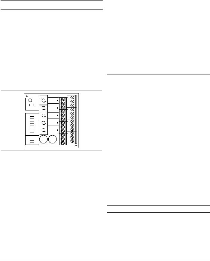
Component descriptions
1 |
2 |
3 |
4 |
5 |
6 |
7 |
8 |
|
|
|
9 |
|
|
PRG |
10 |
11 |
12 |
13 |
|
(1)Main AC wiring block and fuse holder: Provides connections for 120 or 230 volt AC (primary power) from dedicated service. Includes a primary power fuse (5 A).
(2)Dual Transformer AC wiring block: Ten-zone panel only. Provides connections between primary side of both main and expander transformer and 120 or 230 volt AC (fused primary power).
(3)Transformer: Changes 120 or 230 volt AC supply voltage to 24 volt AC.
(4)Power expander transformer (XTR3A120, XTR3A230):
Optional. Available for the ten-zone panel only. Provides
additional primary power to increase the available NAC current for the ten-zone panel.
(5)Main circuit board: Provides connections for all circuits. Also includes the operator interface.
(6)FSDACT plug: Used to connect the FSDACT to the circuit board.
(7)Operator Interface: Includes operator controls, LED indicators, and circuit identification labels.
(8)Cabinet enclosure: Houses the panel electronics and standby batteries. In some cases the batteries may be housed in an external battery cabinet (BC-2).
(9)FSDACT: Optional. Digital alarm communicator transmitter. Provides LCD display for status messages and programming menus. Provides two telephone line connections for sending system messages to a compatible digital alarm communicator receiver (DACR). Includes an event history log of panel and FSDACT events.
(10)Program jumper PRG: Used to place the panel in programming mode.
(11)Tie wrap mounts: Nonpower-limited. Used to secure wires and to help maintain proper separation between powerlimited and nonpower-limited conductors.
(12)Tie wrap mounts: Power-limited. Used to secure wires and to help maintain proper separation between power-limited and nonpower-limited conductors.
(13)Standby batteries: Provide secondary/standby power to the panel electronics in the absence of primary power.
FireShield Technical Reference Manual |
1.3 |

System overview and operation
Operating the panel
Resetting the panel
Pressing Reset places the panel in the reset state. The panel should not be reset until the appropriate authority has determined that the hazard is no longer present.
When you reset the panel:
•All LEDs on the panel light for five seconds
•The trouble and power lights remain on for an additional 15 seconds
•When reset is complete, the buzzer sounds (then turns off) and the trouble LED turns off
In this state:
•All panel indicators are temporarily cleared
•All notification appliances are turned off
•All latched IDCs are cleared
•Alarm, trouble, and supervisory relays are returned to the inactive state
•Auxiliary power (if programmed as resettable) momentarily turns off
At the conclusion of the reset, if an IDC is in an off-normal state, the panel treats the event as a new event and activates the programmed responses. Pressing Disable for the active IDC within 30 seconds after the panel has reset turns off the NACs and disables the IDC.
If one or more IDCs are disabled prior to initiation of the reset, those IDCs remain disabled.
If signal silence inhibit or reset inhibit is enabled, system reset is inhibited during the silence or reset inhibit period.
To reset the panel:
1.Press the Reset button.
Silencing panel and FSRSI buzzers
Both the panel and the optional FSRSI module have buzzer silence buttons. Pressing the Panel Silence button silences the buzzer on the panel and on remote FSRSIs.
Pressing the FSRSI Silence button silences the buzzer on the FSRSI only.
To silence the panel buzzer:
1.Press the Panel Silence button on the panel.
2.Determine the type of condition that caused the buzzer to sound: alarm, trouble, supervisory, or monitor.
3.Determine the cause of the condition.
To silence an FSRSI buzzer:
1.Press the Silence button on the FSRSI.
2.Determine the type of condition that caused the buzzer to sound: alarm, trouble, supervisory, or monitor.
3.Determine the cause of the condition.
Silencing notification appliances
Pressing the Signal Silence & Drill button turns off all audible devices. Visual devices or NAC circuits may or may not turn off, depending on panel programming.
When you silence the signals, the Signal Silenced LED lights, indicating that the notification appliances are off. The panel does not indicate a trouble condition. If GENESIS, horn/strobe, or horn-only devices are used on NACs programmed for GENESIS operation, Signal Silence & Drill silences only the horns.
WARNING: The notification appliances should not be silenced until the building is fully evacuated and the cause of the alarm has been determined.
To silence notification appliances:
1.Press the Signal Silence & Drill button.
When the auto signal silence timer is programmed
When an event activates the notification appliances, the 20minute auto signal silence timer is activated. The notification appliances are activated for the 20-minute period. When the timer expires, any NACs that are programmed as silenceable are deactivated, and the Signal Silenced LED is illuminated.
If another event takes place that activates the previously silenced notification appliances, the Signal Silenced LED turns off. At any time, you can deactivate silenceable NACs by pressing Signal Silence & Drill.
Note: NACs activated by IDCs programmed as waterflow cannot be silenced until the activated devices are restored to normal. After the devices restore, the Signal Silence & Drill button or the auto signal silence timer can silence the NACs.
Resounding an alarm condition
Pressing the Signal Silence & Drill button again turns the audible devices back on if they were silenced.
To resound notification appliances:
1.Press the Signal Silence & Drill button.
Note: NACs resound automatically if a new alarm (from another IDC) is received.
1.4 |
FireShield Technical Reference Manual |

Disabling an IDC
Pressing an IDC Disable button prevents the panel from responding to any status change from that IDC. When you disable an IDC:
•The common Disable LED double-flashes
•The IDC Trouble LED double-flashes
•The common Trouble LED lights and the panel goes into a trouble state
•The common trouble relay changes state
Resetting the panel has no effect on a disabled IDC, but removing all power from the panel clears the disable and enables the IDC.
Note: During an alarm condition, all flashing LEDs go steady.
To disable an IDC:
1.Press the Disable button for the IDC that you want to disable.
Disabling a NAC
When you disable an NAC:
•The common Disable LED double-flashes
•The NAC Trouble LED double-flashes
•The common Trouble LED lights and the panel goes into a trouble state
•The common trouble relay changes state
Resetting the panel has no effect on a disabled NAC, but removing all power from the panel clears the disable and enables the NAC.
To disable a NAC:
1.Press the Disable button for the NAC that you want to disable.
Re-enabling an IDC or NAC
You can re-enable a disabled IDC or NAC. When you reenable an IDC or NAC:
•The common Disable LED turns off
•The IDC or NAC trouble LED turns off
•The common Trouble LED turns off and the panel returns to normal
•The IDC or NAC LEDs are updated to show current status (e.g. if the IDC or NAC is in trouble, the Trouble LED lights). After enabling an IDC, alarms from that IDC are inhibited for 30 seconds. During this time the IDC can be disabled to avoid an unwanted alarm.
System overview and operation
To re-enable an IDC or NAC:
1.Press the Disable button for the IDC or NAC you want to re-enable.
Using the drill command
You can use the drill command to activate all of the notification appliance circuits. Pressing Drill activates all audibles and visuals according to the panel programming, but does not activate the Alarm relay. The FSDACT can be programmed to transmit a drill condition, but it will never report the drill as an alarm. Drill will not operate with an active alarm or supervisory event at the panel.
To perform a fire drill:
1.Press and hold the Signal Silence & Drill button for one second.
2.To stop the drill, press and hold the Signal Silence & Drill button for one second.
Using the walk test command
A walk test lets you test IDC zones without having to create an actual alarm condition. You can conduct a walk test in silent or audible mode. In silent mode the audible devices (NACs) do not sound. Walk test will not operate with an active alarm or supervisory event at the panel.
Zones should be placed in walk test one at a time. This allows the balance of the system to remain in service.
In a walk test, the panel responds to the first signal it receives and ignores all others on that IDC until it clears that signal or the panel is reset. The input must be restored to the normal state before the next input is tested. When the input is restored, the panel automatically resets the circuit being tested. The automatic reset takes eight seconds. After the circuit is reset the next device can be tested.
The panel terminates the walk test if any of the following occur:
•The panel enters an alarm or supervisory state
•There are 30 minutes of inactivity on the zone being tested
•The panel is reset
•Walk Test is pressed
When you press Walk Test:
•The Walk Test LED flashes for an audible walk test and is steady for a silent walk test
•The panel enters a trouble state. There is no fire protection for the IDC in walk test. If an unselected IDC goes into alarm or trouble, all programmed outputs operate as programmed.
FireShield Technical Reference Manual |
1.5 |

System overview and operation
The IDC you are testing behaves as follows:
•For alarm events, the appropriate panel, FSRSI, and FSRZI-A LEDs and buzzers are turned on
•In the audible test mode the notification appliances sound for a number of times equal to the zone number (e.g. three rings for zone three)
•After activation, the panel resets the IDC. This will take eight seconds. During the reset period, the IDC trouble LED fast-flashes. If the device being tested is not restored, the IDC does not reset. If the device is restored (no alarm is present) the panel is ready to test another device or detector.
•If auxiliary power is programmed as resettable, the auxiliary power is deactivated while the zone is reset
•Input zones programmed as waterflow with retard require 10 to 15 seconds of activation to initiate the test signals
•For trouble events, the appropriate LEDs and the buzzers are turned on. In the audible (NAC) test mode a onesecond pulse sounds on the audible devices. After sounding, the zone resets in preparation for continued testing.
•For ground fault events, the appropriate LEDs and the buzzers are turned on. In the audible (NAC) test mode a one-second pulse sounds on the audible devices. After sounding, the zone resets in preparation for continued testing.
To conduct an audible walk test:
1.Press the Walk Test button once.
2.Press the Disable button for the IDC you want to test.
3.Conduct your walk test for the IDC.
4.When you are finished testing an IDC, press the Disable button to turn off the walk test for that IDC.
5.Select another IDC to walk test (steps 2 through 4) or exit from the walk test by pressing the Walk Test button.
To conduct a silent walk test:
1.Press the Walk Test button two times.
2.Press the Disable button for the IDC you want to test.
3.Conduct your walk test for the IDC.
4.When you are finished testing an IDC, press the Disable button to turn off the walk test for that IDC.
5.Select another IDC to walk test (steps 2 through 4) or exit from the walk test by pressing the Walk Test button.
Conducting lamp tests
Panel lamp test
A panel lamp test lights all the LEDs on the panel, FSRSIs, and FSRZI-As so you can verify proper operation.
To test panel lamps:
1.Press and hold the Remote Disconnect and Walk Test buttons simultaneously.
2.Verify proper operation of all LEDs on the panel.
During lamp tests the LCD displays:
DB# xx P: x.yy.zz
D: x.yy.zz
Where: DB# is the database revision number
P: x.yy.zz is the main panel version
D: x.yy.zz is the FSDACT version
FSRSI and FSRZI-A lamp test
FSRSI and FSRZI-A modules can be installed individually or in groups to create a complete remote annunciator. You can perform a local lamp test on the FSRSI and FSRZI-A. An FSRSI is required to initiate this function.
To do an FSRSI and FSRZI-A lamp test:
1.Press and hold the FSRSI Silence button for five seconds.
2.Verify proper operation of all LEDs on the FSRSI and FSRZI-As.
1.6 |
FireShield Technical Reference Manual |

System overview and operation
FSDACT LCD messages
Message |
Description |
Peripheral trouble |
The panel lost communications with the |
|
peripherals |
Battery Bad |
The battery is bad and needs to be |
|
replaced |
Battery Missing |
The battery is no longer connected |
AC Failure |
The panel lost AC power |
|
|
Charger Trouble |
The panel detected a battery charger |
|
trouble condition. The charger may not |
|
be able to charge the batteries. |
Ground Fault |
The panel detected a ground fault |
Transformer 2 TR |
The panel detected a trouble condition |
|
in the Power Expander Transformer |
AUX Power Troub |
The panel detected a trouble condition |
|
in the AUX power circuit. |
Internal Comm TR |
Panel-to-FSDACT communication fault |
RRM(s) disabled |
One or more FSRRMs are disabled |
|
|
Dialing... |
The FSDACT is dialing a DACR |
DACT Configuration |
FSDACT is not programmed or has |
TRBL |
unverified changes |
DACT Delivery TR |
FSDACT failed to deliver a message to |
|
the receiver or CMS |
DACT Line 1 Trbl |
A ground fault or line fault has been |
|
detected on Line 1 of the FSDACT |
DACT Line 2 Trbl |
A ground fault or line fault has been |
|
detected on Line 2 of the FSDACT |
FireShield Technical Reference Manual |
1.7 |
System overview and operation
1.8 |
FireShield Technical Reference Manual |
Chapter 2
Installation
Installation checklist
Prepare the site: Make sure the installation location is free from construction dust and debris and extreme temperature ranges and humidity.
Unpack the equipment
Install the cabinet: See “Installing the cabinet” for cabinet dimensions.
Remove the clear protective plastic from the front panel display
Install optional components (FSRSI, FSDACT, etc.):
See module installation instructions in this chapter.
Set the panel jumpers: See Appendix C or the panel label.
Review wire routing: See Appendix C or the panel label.
Connect the field wiring: See Appendix C or the panel label. Meter for opens, grounds, and shorts before connecting.
Connect AC power and ground: See Appendix C or the panel label. Panel can not be started on batteries only.
WARNING: Make sure that the AC power circuit breaker is off before connecting wires to the terminal block.
Connect batteries: See Appendix C or the panel label.
Program the panel: Refer to Chapter 3.
Test for proper operation
Installing the cabinet
Cabinets can be surfaced mounted or semi-flush mounted. See the “Panel dimensions” figure and table for framing and mounting dimensions.
To surface mount the cabinet:
1.Position the cabinet on the finished wall surface.
2.Fasten the cabinet to the wall surface where indicated.
To semi-flush mount the cabinet:
1.Frame the interior wall as required to support the full weight of the cabinet and standby batteries.
2.Install (optional) semi-flush trim to cabinet.
3.Fasten the cabinet to the framing studs where indicated.
Panel dimensions
Model |
D1 [1] |
D2 |
D3 |
D4 |
D5 [1] |
Three- |
16.5 in |
3.75 in |
9.13 in |
10.5 in |
14.23 in |
and five- |
(41.9 |
(9.5 cm) |
(23.2 |
(26.67 |
(36.14 |
zone |
cm) |
|
cm) |
cm) |
cm) |
Ten- |
23.65 in |
3.75 in |
7.75 in |
21.27 in |
16.25 in |
zone |
(60 cm) |
(9.5 cm) |
(19.7 |
(54.0 |
(41.27 |
|
|
|
cm) |
cm) |
cm) |
[1] Add 1-1/2 in (3.81 cm) to D1 and D5 dimensions for trim kit.
 D2
D2

 D3
D3
|
holes |
|
D1 |
mountingflush-Semi |
Surface mounting holes |
|
D4 |
D5
FireShield Technical Reference Manual |
2.1 |
Installation
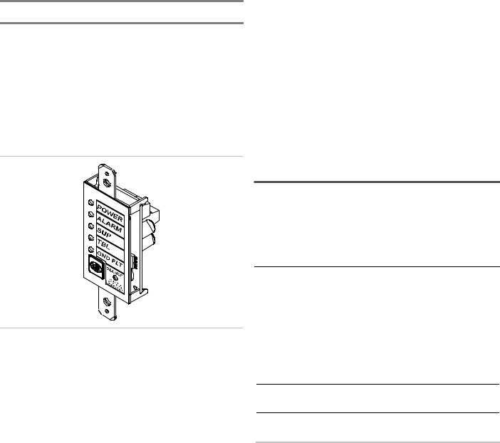
Installing the Remote System Indicator
The Remote System Indicator (FSRSI) is a supervised remote annunciator that provides remote LED indication of power, alarm, supervisory, trouble, and ground fault conditions. A sounder gives audible indication during a trouble, alarm, or supervisory condition. The sounder can be silenced with the FSRSI Silence switch.
Note: You must run the Find Annunciators program option after adding or removing a remote annunciator. The remote annunciators will not operate properly until the panel detects them. For more information see Chapter 3 “Programming.”
Specifications
Max. per system: 2 Voltage range
Minimum: 21 Vdc
Maximum: 25 Vdc Current requirements
Standby: 12 mA
Alarm: 48 mA
Max. circuit capacitance: 0.03 F Max. circuit resistance: 13 ohms Wire size
Minimum: 18 AWG (0.75 sq mm) Maximum: 12 AWG (2.5 sq mm)
Compatible electric box: ANSI/NEMA OS1-1996 1-3 gang electrical box
Operating environment
Temperature: 32 to 120 °F (0 to 49 °C) Humidity: 93% RH, noncondensing
LEDs and buzzer
LED |
State |
Description |
Power (green) |
On |
AC power present |
Alarm (red) |
On |
Active alarm state |
LED |
State |
Description |
Supervisory |
On |
Active supervisory device |
(yellow) |
|
|
Trouble (yellow) |
On |
System trouble |
|
|
|
Ground fault |
On |
System ground fault |
(yellow) |
|
|
Buzzer |
On |
System trouble |
|
On (temporal) |
Alarm condition |
|
On (slow pulse) |
Supervisory condition |
|
On (intermittent) |
AC fail |
|
Off |
Normal or silenced |
|
|
|
Jumper setup |
|
|
Jumper |
Name |
Description |
J2 |
Group |
Allows two FSRSIs to be connected |
|
jumper |
to the same panel. |
|
|
Install the jumper on only one of the |
|
|
two FSRSIs. |
Note: For jumper location, refer to the FSRSI wiring diagram.
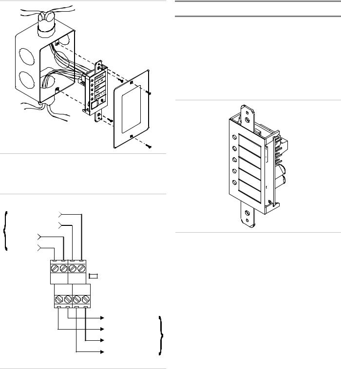
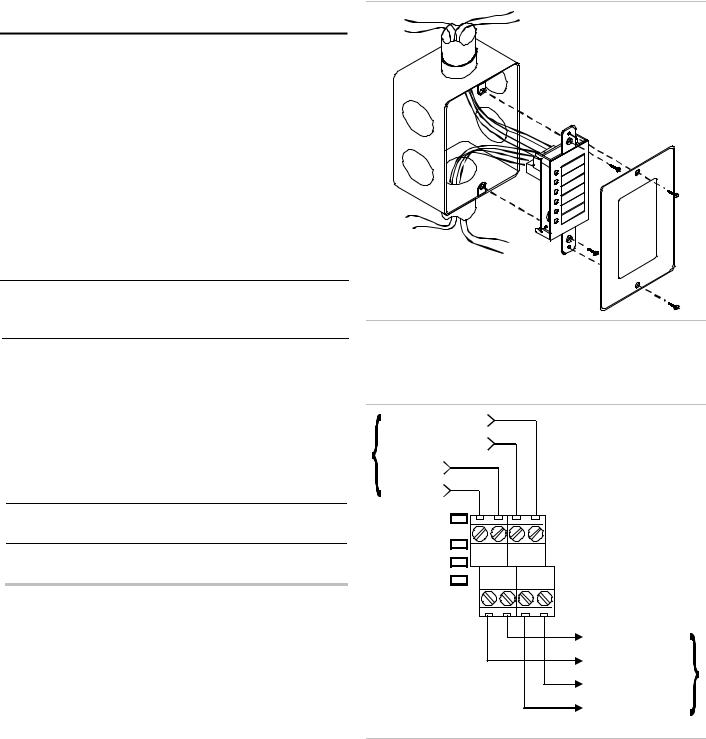
Installation instructions
A single FSRSI can be mounted in a standard, single gang electrical box (ANSI/NEMA OS1-1996) using the single gang cover plate that is included. Up to three FSRZI-As with or without an FSRSI can be mounted in an approved multiple gang electrical box (ANSI/NEMA OS1-1996) with appropriate two, three, or four gang cover plates (model numbers FSAT-2, FSAT-3, or FSAT-4).
Caution: Make sure all power is disconnected from the panel before installing. Observe static-sensitive handling practices.
To install the FSRSI:
1.Verify that all field wiring is free of opens, shorts, and ground faults.
2.Connect wires to the FSRSI as shown (see wiring diagram).
3.Using the two plain machine screws provided, mount the module to the electrical box.
Note: If you are using a surface mounting box, you must install washers (provided) between the FSRSI and the surface mounting box.
4.Using the white machine screws provided with the faceplate, mount the faceplate to the module.
5.Connect the wires to the terminals in the control panel.
6.Program the FSRSI using the Find Annunciators program option. Refer to Chapter 3 “Programming.”
2.2 |
FireShield Technical Reference Manual |
 Compatible electrical box
Installing the FSRSI in an electrical box
Wiring diagram
From control panel or previous device
Communication in -
Communication in +
24 V in +
24 V in -
|
|
|
|
Group |
24V IN |
C |
IN |
J2 |
|
|
||||
- |
+ |
+ |
- |
|
24V OUT C OUT |
||||
- |
+ |
|
+ |
- |
24 V out +
24 V out - Communication out - Communication out +
To next device
Notes
1.All wiring is supervised and power limited.
2.24 V out (aux power) must be programmed as nonresettable.
Installation
Installing the Remote Zone Indicator
The Remote Zone Indicator (FSRZI-A) is a supervised remote annunciator that provides remote LED indication of IDCs in alarm state. The FSRZI-A indicates conditions for five IDCs. The IDC groups are set by jumpers to indicate zones 1–5 or zones 6–10. Paper inserts are provided for labeling the LEDs.
Note: You must run the Find Annunciators program option after adding or removing a remote annunciator. The remote annunciators will not operate properly until the panel detects them. For more information see Chapter 3 “Programming.”
Specifications
Max. per system
FS302 (three-zone): 2
FS502 (five-zone): 2
FS1004 (ten-zone): 4 Voltage range
Minimum: 21 Vdc
Maximum: 25 Vdc Current requirements
Standby: 8 mA
Alarm: 35 mA
Max. circuit capacitance: 0.03 F Max. circuit resistance: 13 ohms Wire size
Minimum: 18 AWG (0.75 sq mm) Maximum: 12 AWG (2.5 sq mm)
Compatible electric box: ANSI/NEMA OS1-1996 1-3 gang electrical box
Operating environment
Temperature: 32 to 120 °F (0 to 49 °C) Humidity: 93% RH, noncondensing
FireShield Technical Reference Manual |
2.3 |
Installation
Jumper setup
Jumper |
Name |
Description |
J2 |
Reserved |
N/A |
|
for future |
|
|
use |
|
J3 |
Zone 6 - |
Sets the five LEDs to report alarms |
|
10 |
in zones 6 - 10. [1] |
|
jumper |
|
J4 |
Zone 1- 5 |
Sets the five LEDs to report alarms |
|
jumper |
in zones 1 - 5. [1] |
J5 |
Group |
Allows two FSRZI-As to be |
|
jumper |
connected to the same panel and |
|
|
set to the same zone output option. |
Install the jumper on FSRZI-As in only one of the two groups.
[1] Install only one zone jumper on J3 or J4.
Note: For jumper location, refer to the FSRZI-A wiring diagram.
Installation instructions
A single FSRZI-A can be mounted in a standard, single gang electrical box (ANSI/NEMA OS1-1996) using the single gang cover plate that is included. Up to three FSRZI-As with or without an FSRSI can be mounted in an approved multiple gang electrical box (ANSI/NEMA OS1-1996) with appropriate two, three, or four gang cover plates (model numbers FSAT-2, FSAT-3, or FSAT-4).
Caution: Make sure all power is disconnected from the panel before installing. Observe static-sensitive handling practices.
To install the FSRZI-A:
1.Verify that all field wiring is free of opens, shorts, and ground faults.
2.Connect wires to the FSRZI-A as shown (see wiring diagram).
3.Using the two plain machine screws provided, mount the module to the electrical box.
Note: If you are surface mounting the FSRZI-A, you must install washers (provided) between the FSRZI-A and the surface mount box.
4.Using the two white machine screws provided with the faceplate, mount the faceplate to the module.
5.Connect the wires to the terminals in the control panel.
6.Program the FSRZI-A using the Find Annunciators program option. Refer to Chapter 3 “Programming.”
 Compatible electrical box
Installing the FSRZI-A in an electrical box
Wiring diagram
Communication in -
Communication in +
24 V in +
24 V in - |
|
|
|
|
|
|
From control |
|
|
|
|
|
|
panel or |
J5 |
|
|
|
|
|
previous |
|
|
|
|
||
J4 |
|
|
|
|
||
device |
|
|
|
|
||
J3 |
24V IN |
C |
IN |
|||
|
||||||
|
|
- |
+ |
+ |
- |
|
|
J2 |
24V OUT C OUT |
||||
|
|
- |
+ |
|
+ - |
|
24 V out +
24 V out -
Communication out -
Communication out +
To next device
Notes
1.All wiring is supervised and power limited.
2.24 V out (aux power) must be programmed as nonresettable.
2.4 |
FireShield Technical Reference Manual |
Installation
Installing the Remote Relay Module
The Remote Relay Module (FSRRM) provides five dry contact relay outputs. The outputs can be wired as both normally open and normally closed. The outputs can be set to common or zone notifications (see the “Command options” table below). Installing the appropriate jumper (JP3 - JP5) configures the dry contact relay output options.
Five diagnostic LEDs provide visual indication of the status of each relay. If the LED is lit, the relay is energized. If the LED is off, the relay is de-energized. If configured for common operation the trouble relay and the power relay will be energized when the system is normal.
Note: You must run the Find Annunciators program option after adding or removing a remote annunciator. The remote annunciators will not operate properly until the panel detects them. For more information see Chapter 3 “Programming.”
|
ACTIVE |
|
|
|
DS4 |
TB4 |
|
DISABLE |
OUT 1 |
||
JP1 |
|
||
|
|
||
OUTPUTS |
DS5 |
|
|
JP1 IN |
OUT 2 |
|
|
|
TB3 |
||
MODULE TYPE |
DS2 |
||
JP2 |
OUT 3 |
|
|
ZONE 11-15 |
|
||
|
|
||
JP3 |
DS3 |
TB2 |
|
ZONE 6-10 |
OUT 4 |
||
JP4 |
|||
ZONE 1-5 |
DS1 |
|
|
JP5 |
|
||
OUT 5 |
|
||
COMMON |
TB1 |
||
|
|||
GROUP |
|
||
#1 JP6 IN |
|
||
|
|
||
JP6 |
|
|
|
#2 JP6 OUT |
|
|
Specifications
Max. per system
FS302 (three-zone): 4
FS502 (five-zone): 4
FS1004 (ten-zone): 6
Voltage range
Minimum: 21 Vdc
Maximum: 25 Vdc
Zoned operation current requirements
Standby: 8 mA
Alarm: 65 mA
Command options
Common operation current requirements Standby: 30 mA
Alarm: 41 mA
Max. circuit capacitance: 0.03 F Max. circuit resistance: 13 ohms
Relay ratings: 30 Vdc @ 1 A (resistive load) Wire size
Minimum: 18 AWG (0.75 sq mm) Maximum: 12 AWG (2.5 sq mm)
Mounting: MFC-A cabinet or listed fire alarm enclosure Operating environment
Temperature: 32 to 120 °F (0 to 49 °C) Humidity: 93% RH, noncondensing
Jumper setup
Jumper |
Name |
Description |
JP1 |
Disable |
Disables all outputs. This allows the |
|
jumper |
installer to test the system while the |
|
|
FSRRM is disabled. Removing the |
|
|
jumper reactivates the FSRRM. |
|
|
The disable jumper is supervised. |
|
|
With the disable jumper in place, the |
|
|
panel displays Trouble, Annunciator |
|
|
Trouble, Disable, sounds the panel |
|
|
buzzer, and de-energizes any |
|
|
energized relay. |
JP2 |
Reserved for future use. |
|
|
|
|
JP3 |
Zone 6 - |
Sets the five dry contacts to report |
|
10 jumper |
events on zones 6 through 10. See |
|
|
“Command options” table. [1] |
JP4 |
Zone 1- 5 |
Sets the five dry contacts to report |
|
jumper |
events on zones 1 through 5. See |
|
|
“Command options” table. [1] |
JP5 |
Common |
Sets the five dry contacts to report |
|
jumper |
common events. See “Command |
|
|
options” table. [1] |
JP6 |
Group |
The group jumper (JP6) allows two |
|
jumper |
FSRRMs to be connected to the |
|
|
same panel and set to the same |
output option. Install the jumper (JP6) to only one of the two grouped FSRRMs.
[1] Install only one zone jumper on J3 or J4 or J5.
Module type |
Jumper |
Output 1 |
Output 2 |
Output 3 |
Output 4 |
Output 5 |
|
Common |
JP5 |
Alarm |
Trouble [1] |
Supervisory |
Monitor |
Power [1] |
|
Zone 1 |
- 5 |
JP4 |
Zone 1 |
Zone 2 |
Zone 3 |
Zone 4 |
Zone 5 |
|
|
|
|
|
|
|
|
Zone 6 |
- 10 |
JP3 |
Zone 6 |
Zone 7 |
Zone 8 |
Zone 9 |
Zone 10 |
[1] Under normal conditions the relay is energized (the internal LED is lit). Loss of power de-energizes the relay.
FireShield Technical Reference Manual |
2.5 |
Installation
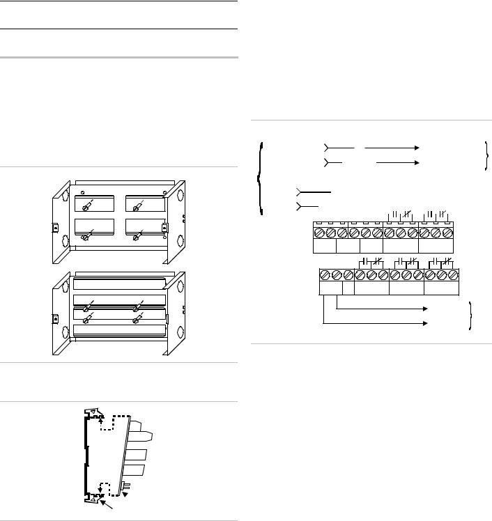
Installation instructions
The FSRRM snaps into a snap track (shipped with the FSRRM), which mounts inside a listed fire alarm enclosure. The FSRRM can be positioned in the snap track with the terminal block facing vertically or horizontally.
Caution: Make sure all power is disconnected from the panel before installing. Observe static-sensitive handling practices.
To install the FSRRM:
1.Mount the MFC-A cabinet using the installation sheet provided (P/N 387453).
2.Drill mounting holes in the snap track using the template provided (P/N 3100463). These holes will align to the mounting holes on the MFC-A. An optional extended track (P/N FSRRM-S11) is available for mounting two to four FSRRM modules.
3.Mount the snap track to the MFC-A cabinet.
|
MFC-A |
Snap |
Snap |
track |
track |
MFC-A |
Snap |
track |
Snap |
track |
5.Verify that all wiring is free of opens, shorts, and ground faults.
6.Connect the FSRRM to the panel or other peripheral devices.
7.Power up the panel and confirm that all relays are in the correct state before connecting the field wiring.
8.Connect field wires to the FSRRM as shown in the wiring diagram. Be sure connection will not adversely affect controlled devices (e.g. elevators, fans, etc.).
9.Connect wiring to the controlled devices.
10.Program the FSRRM using the Find Annunciators program option. Refer to Chapter 3 “Programming.”
Wiring diagram
From control panel |
|
|
|
|
|
|
|
|
|
|
|
|
|
|
|
|
To next device |
|
or previous device |
|
|
|
|
|
|
|
|
|
|
|
|
|
|
|
|
||
Communication in + |
[1] |
|
|
|
|
|
|
|
[1] |
Communication out - |
||||||||
|
|
|
|
|
|
|
||||||||||||
Communication in - |
|
|
|
|
|
|
|
Communication out + |
||||||||||
|
|
|
|
|
|
|
|
|
|
|||||||||
|
|
|
|
|
|
|
|
|||||||||||
24 V in - |
|
|
|
|
|
|
|
|
|
|
|
|
|
|
|
|
|
|
|
|
|
|
|
|
|
|
|
|
|
|
|
|
|
|
|
||
[1] |
|
|
|
|
|
[2] |
[2] |
|
|
|
||||||||
24 V in + |
|
|
|
|
|
|
|
|
||||||||||
|
|
|
|
|
|
|
|
|
|
|
|
|
|
|
|
|
|
|
|
|
|
|
|
|
|
|
|
|
|
|
|
|
|
|
|
|
|
|
|
|
|
|
|
|
|
|
|
|
|
|
|
|
|
|
|
|
24V IN |
C |
IN |
C OUT |
OUT 3 |
OUT 1 |
|
+ |
- |
- |
+ |
- + |
NO C NC NO C NC |
|
|
|
|
[2] |
[2] |
[2] |
|
24V OUT |
X |
OUT 5 |
OUT 4 |
OUT 2 |
||
+ |
- |
|
NO C NC NO C NC NO C NC |
|||
|
|
|
|
|
[1] |
24 V out - |
|
|
|
|
|
24 V out + |
|
|
|
|
|
|
|
|
|
|
|
|
|
|
To next device |
4.Insert one side of the FSRRM into the first snap track slot and snap in the opposite side.
Mount in first slot only
 RRM
RRM
Snap track
Notes
[1]Supervised and power limited.
[2]Must be connected to a power limited source.
3.24 V out (aux power) must be programmed as nonresettable.
Service and troubleshooting
If the Disabled and Annunc Trouble LED are lit but no IDC or NAC is disabled then the FSRRM output is disabled.
2.6 |
FireShield Technical Reference Manual |
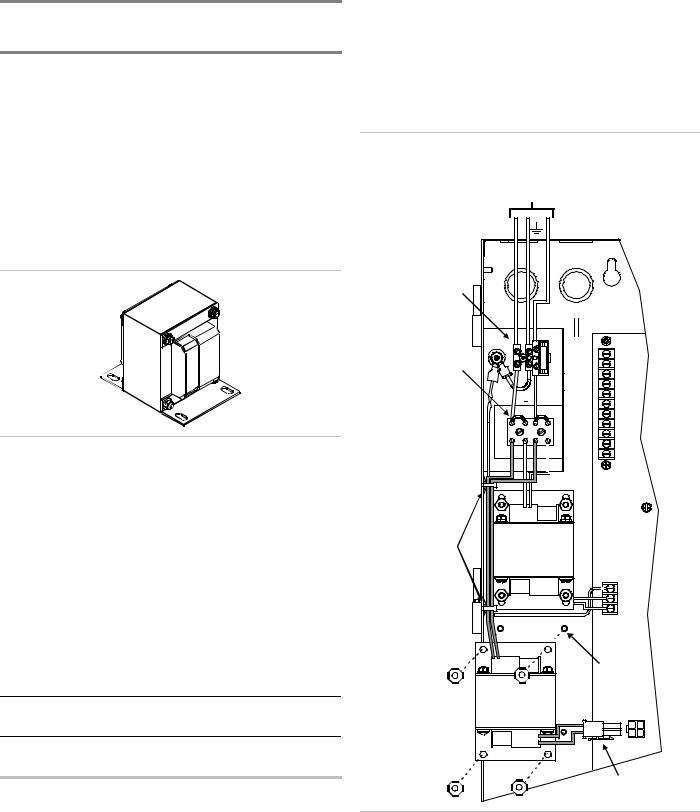
Installing the Power Expander
Transformer
The Power Expander Transformer (XTR3A120, XTR3A230) provides additional primary AC power to increase the NAC capacity for the ten-zone panel. It provides an additional 2.5 amps of NAC current. The Power Expander Transformer installs in the cabinet with four nuts (provided). The input side of the Power Expander Transformer connects to 120 Vac or 230 Vac through the Dual Transformer AC Wiring Block. Its output connects to the circuit board (J4) with the attached cable harness. One Power Expander Transformer can be installed in the 10-zone panel.
Note: The Power Expander Transformer does not work with the three-zone or five-zone panels.
Specifications
Power input
120 Vac @ 60 Hz (P/N XTR3A120)
230 Vac @ 50/60 Hz (P/N XTR3A230) Operating environment
Temperature: 32 to 120 °F (0 to 49 °C) Humidity: 93% RH, noncondensing
Fuse: Primary winding has thermal current protection and is not field serviceable
Note: Input current rating is included with the overall ten-zone ratings.
Installation instructions
Caution: Make sure all power is disconnected from the panel before installing. Observe static-sensitive handling practices.
To install the Power Expander Transformer:
1.Position the Power Expander Transformer so that the mounting holes align with the four mounting studs on the control panel cabinet.
2.Secure the transformer to the panel using the four nuts provided.
Installation
3.Connect the cable harness to J4 on the circuit board. Push the cable harness until the connector clicks into place.
4.Connect the incoming power wires to the dual transformer AC wiring block above the existing transformer.
5.Secure the incoming power wires to the side of the control panel with the tie strap provided.
From 120 Vac, 15 A, 60 Hz Dedicated branch circuit —OR—
From 230 Vac, 15 A, 50/60 Hz Dedicated branch circuit
Main AC wiring block and fuse holder
Dual transformer AC wiring block
Tie wrap mounts
N L
Cabinet
Fuse
N2  L2
L2
N L 

Main
controller Main board transformer
TB1
Mounting
 studs XTR
(optional
transformer)
J4
Plug connector
Power Expander Transformer installation and wiring
FireShield Technical Reference Manual |
2.7 |
Installation
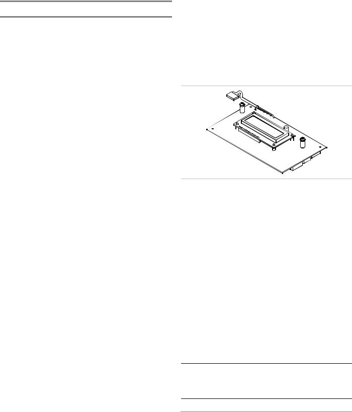
Installing the FSDACT
The FSDACT is a digital alarm communicator transmitter (DACT) that transmits panel events to a compatible digital alarm communicator receiver (DACR). Messages are transmitted over standard loop-start telephone lines. The dialer is capable of split reporting to two different account and telephone numbers.
In addition to the DACT functions, this module includes:
•An alphanumeric LCD to display system messages and programming prompts
•An event history log of panel and DACT events, viewable through compatible software
•A modem for uploading and downloading panel configuration, history, and current status to a PC running compatible software
Note: The FSDACT modem is only rated for 2400 baud communication. Some PC modems may not be compatible with this baud rate.
The FSDACT can be programmed to operate as a single or dual line DACT/Modem/LCD display, a Modem/LCD display, or an LCD display only. For the FSDACT to be NFPA 72 CS compliant, the following is required:
1.The factory installed warning label must be removed from the FSDACT's line two phone jack.
2.A second phone line, independent of that used for line one must be connected to phone jack two.
3.The FSDACT must be programmed for dual line operation.
4.The FSDACT must be programmed for a daily transmission test frequency.
UL 864 compliance requires the dual line setting.
The FSDACT can be configured for attended or unattended downloading. JP1 is a wire loop (located near the top of the FSDACT) that controls which download method is used.
Leaving the JP1 wire loop intact configures the FSDACT for attended downloading. The panel will not allow changes to the panel or dialer configuration unless the program jumper is inserted. It will allow changes to receiver information (account code, telephone numbers, etc.). UL requires the red wire loop to be intact for all remote station systems.
Cutting the JP1 wire loop configures the FSDACT for unattended downloading. This means that the program jumper need not be inserted to accept any panel or dialer configuration changes.
NFPA 72 1999 edition states in 7-1.6.2.1 that reacceptance testing shall be performed after any change to site-specific software.
"All components, circuits, systems operations, or site-specific software functions known to be affected by the change or identified by a means that indicates the system operational
changes shall be 100 percent tested. In addition, 10 percent of initiating devices that are not directly affected by the change, up to a maximum of 50 devices, also shall be tested, and correct system operation shall be verified. A revised record of completion in accordance with 1-6.2.1 shall be prepared to reflect any changes.”
For additional download security, the FSDACT can be programmed to perform a call back function. This call back option applies whether the FSDACT is configured for attended or unattended downloading.
Specifications
Current requirements Standby: 40 mA Alarm: 60 mA
Operating environment
Temperature: 32 to 120 °F (0 to 49 °C) Humidity: 93% RH, noncondensing
Phone line type: one or two loop-start lines on a public, switched network
Phone line connector: RJ31/38X (C31/38X). Two 7 ft plug cords are shipped with the FSDACT.
FCC registration number: US: EDWAL01BFSDACT Ringer equivalence number: 0.1
Industry Canada Registration number: IC: 3944-FSDACT Connection between panel and FSDACT: 6-pin connector Communication formats: Contact ID (SIA DC-05) and
EST 4/2 (SIA DC-02 P3 with hexadecimal event codes)
Installation instructions
Note: It is not necessary to remove the main panel board from the cabinet to install the dialer.
Caution: Make sure all power is disconnected from the panel before removing or installing an FSDACT. Failure to disconnect power will damage the panel and the FSDACT. Observe static-sensitive handling practices.
To install the FSDACT:
1.Remove the blank insert from the display window.
2.Remove the clear protective plastic film from the FSDACT LCD display.
2.8 |
FireShield Technical Reference Manual |
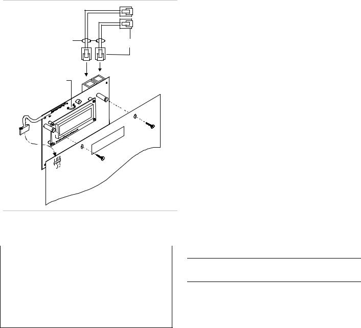
3.Use JP1 to configure the FSDACT for attended or unattended downloading:
•Attended: leave the JP1 wire intact
•Unattended: cut the JP1 wire
4.Install the dialer to the back of the circuit board. Align the LCD display with the opening in the circuit board.
5.Secure the dialer to the circuit board with the two machine screws provided.
6.Connect the power cable to J2 on the control panel.
7.Connect RJ31X/C31X jacks to the supplied cables.
8.Connect the telephone circuits as required.
Line 1 |
|
Line 2 |
To wall |
phone jack |
|
Phone cables |
RJ31 jacks |
(supplied) |
JP1 jumper wire
Circuit board
FSDACT installation and telephone circuit connection
The FSDACT is listed for use with the following DACRs
Receiver |
Models |
Formats |
Ademco |
685 |
EST 4/2*, Contact ID |
FBII |
CP220 |
EST 4/2*, Contact ID |
Osborne-Hoffman |
OH 2000 |
EST 4/2*, Contact ID |
Radionics |
D6500 |
EST 4/2* |
Silent Knight |
9000 |
EST 4/2* |
Sur-Gard |
MLR1, MLR2, |
EST 4/2*, Contact ID |
|
MCDI TLR, TLR+ |
|
* EST 4/2 is SIA DCS-02 P3 with the ability to transmit hexadecimal event codes.
Installation
FCC Information
1.The dialer complies with Part 68 of the FCC rules. The dialer’s FCC certification number and Ringer Equivalence Number (REN) is displayed on the panel’s programming label and in this manual. This information must be provided to the telephone company if requested.
2.Two FCC compliant telephone cords with 8-pin modular plugs at both ends are supplied with the FSDACT. The dialer is designed to be connected to the telephone network using the supplied cord and an RJ31X or RJ38X jack, which must also comply with FCC Part 68 rules.
3.The REN is used to determine the maximum number of devices that may be connected to a single telephone circuit. All telephone devices are assigned a REN. The sum of the RENs for all connected devices may not exceed five. The maximum REN may vary in some areas. Contact the local telephone provider for more information.
4.If the dialer causes harm to the telephone network, the telephone company will notify you an advance that temporary discontinuance of service may be required. If advance notice is not practical, the telephone company will notify you as soon as possible. You will also be advised of your right to file a complaint with the FCC, if you believe it is necessary.
5.The telephone company may make changes in its facilities, equipment, operations, or procedures that could affect the operation of the dialer. If this happens, the telephone company will provide advance notice in order for you to make necessary modifications to maintain uninterrupted service.
6.If trouble is experienced with the dialer, for repair or warranty information, contact the manufacturer at: (941) 739-4200. If the dialer is causing harm to the telephone network, the telephone company may request you disconnect the dialer until the problem is resolved.
7.No repairs may be performed on the dialer by the user.
8.The dialer can not be used on public coin phones or party line service provided by the telephone company.
Industry Canada Information
NOTICE: This equipment meets the applicable Industry Canada Terminal Equipment Technical Specifications. This is confirmed by the registration number. The abbreviation, IC, before the registration number signifies that registration was performed based on a Declaration of Conformity indicating that Industry Canada technical specifications were met. It does not imply that Industry Canada approved the equipment.
Before installing this equipment, users should ensure that it is permissible to be connected to the facilities of the local telecommunications company. The equipment must also be installed using an acceptable method of connection.
The customer should be aware that compliance with the above conditions may not prevent degradation of service in some situations.
Repairs to certified equipment should be coordinated by a representative designated by the supplier. Any repairs or alterations made by the user to this equipment, or equipment malfunctions, may give the telecommunications company cause to request the user to disconnect the equipment.
Users should ensure for their own protection that the electrical ground connections of the power utility, telephone lines, and internal metallic water pipe system, if present, are connected together. This precaution may be particularly important in rural areas.
Caution: Users should not attempt to make connections themselves, but should contact the appropriate electric inspection authority, or electrician, as appropriate.
NOTICE: The Ringer Equivalence Number (REN) for this terminal equipment is 0.1. The REN assigned to each terminal equipment provides an indication of the maximum number of terminals allowed to be connected to a telephone interface. The termination on an interface may consist of any combination of devices subject only to the requirement that the sum of the Ringer Equivalence Numbers of all the devices does not exceed five.
FireShield Technical Reference Manual |
2.9 |
Installation
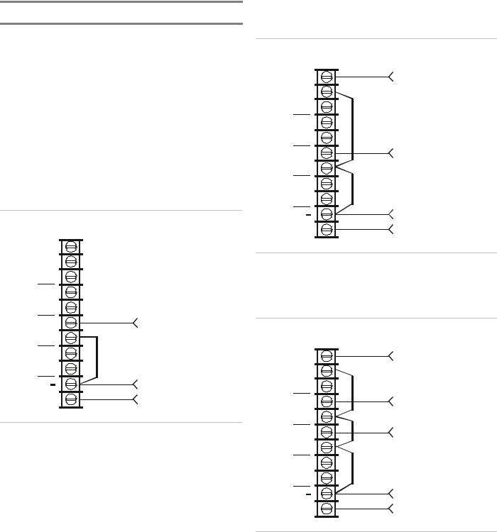
Connecting an RPM module
The Reverse Polarity Module (RPM) is an interface between FireShield and a reverse polarity receiver. It provides offpremises signal transmission for systems that must comply with NFPA requirements. When used as a reverse polarity remote station transmitter, it can be connected to either a single circuit (alarm or alarm and trouble) or up to three circuits (alarm, supervisory, and trouble).
Note: For detailed information and wiring, refer to the RPM installation sheet P/N 3100430.
Below are application diagrams for using the RPM.
Note: The RPM must be mounted in an MFC-A enclosure immediately adjacent to the panel and in conduit.
Alarm transmitted only
FireShield
TB3
NO |
|
TRBL C |
|
NC |
|
NO |
|
SUP |
|
NO |
From ALRM on RPM |
ALM |
(brown wire) |
|
|
C- |
|
C+ |
From COM on RPM |
|
|
24VOUT+ |
(black wire) |
From +24 on RPM |
|
|
(red wire) |
Alarm and trouble transmitted on a single circuit
Note: JP1 on the RPM must be OUT.
FireShield |
|
TB3 |
|
NO |
From TRBL on RPM |
TRBL C |
(yellow wire) |
|
|
NC |
|
NO |
|
SUP |
|
NO |
From ALRM on RPM |
ALM |
(brown wire) |
|
|
C- |
|
C+ |
From COM on RPM |
|
|
24VOUT+ |
(black wire) |
From +24 on RPM |
|
|
(red wire) |
Alarm, supervisory, and trouble transmitted on separate circuits
Note: JP1 on the RPM must be IN.
FireShield |
|
TB3 |
|
NO |
From TRBL on RPM |
TRBL C |
(yellow wire) |
|
|
NC |
|
NO |
From SUPV on RPM |
SUP |
(orange wire) |
|
|
NO |
From ALRM on RPM |
ALM |
(brown wire) |
|
|
C- |
|
C+ |
From COM on RPM |
|
|
24VOUT+ |
(black wire) |
From +24 on RPM |
|
|
(red wire) |
2.10 |
FireShield Technical Reference Manual |
Connecting a CTM module
The CTM4.7 City Tie Module is an interface between the control panel notification appliance circuit and a master box. It provides off-premises signal transmission for systems that must comply with NFPA requirements for Auxiliary Protective Systems. The CTM4.7 activates a local energy fire alarm box, which provides a 24 Vdc alarm signal (current limited at 200 mA). The 4.7 KΩ end of line resistor required by the NAC is built in to the CTM4.7.
Requirements
When connecting a CTM to the panel, the following hardware and programming requirements must be met:
•The NAC used must be dedicated to CTM use only
•All alarm zones must be programmed to activate the dedicated NAC
•The NAC used must not be programmed for Signal Silence
Specifications
Power: Nominal 24 Vdc @ 200 mA Municipal box operation: Nominal 24 Vdc Maximum wiring resistance: 25 Ω
Trip current: 200 mA into 14.5 Ω coil Maximum current: 300 mA
Standby current: 20 mA Mounting: Single gang box Operating environment
Temperature: 32 to 120 °F (0 to 49 °C) Humidity: 93% RH, noncondensing
The following are wiring diagrams showing how the polarity switches during an alarm condition.
Panel in normal condition
|
|
Normal condition |
|
|
|
|
CTM4.7 |
|
Master box |
|
|
_ |
[1] [2] _ |
|
|
|
1 |
||
_ |
|
|
|
|
+ |
2 |
+ |
|
|
|
2 |
+ |
||
|
_ |
|
||
+ |
1 |
|
|
|
[3] |
[5] |
|
|
|
|
|
Municipal circuit |
||
[4] Notification |
|
|||
|
|
|||
appliance circuit
Installation
Panel in alarm condition
|
|
Alarm condition |
|
|
|
|
CTM4.7 |
Master box |
|
|
|
+ [1] [2] + |
||
|
|
1 |
||
|
|
|
||
+ |
_ |
2 |
_ |
|
2 |
_ |
|||
_ |
[3] + |
1 |
|
|
[4] |
[5] |
Municipal circuit |
||
Notification |
||||
|
||||
appliance circuit
Notes
[1]200 mA into a 14.5 Ω trip coil max., loop resistance = 25 Ω
[2]This circuit is nonpower-limited and is supervised for grounds and opens, but not shorts
[3]Supervised and power-limited
[4]NAC must be programmed for continuous signal
[5]CTM4.7 must be mounted in the same room as the panel
FireShield Technical Reference Manual |
2.11 |
 Loading...