

Page 1
www.edwardssignaling.com
P/N 1030522 • REV D • REB 20MAR13
Integrity Series
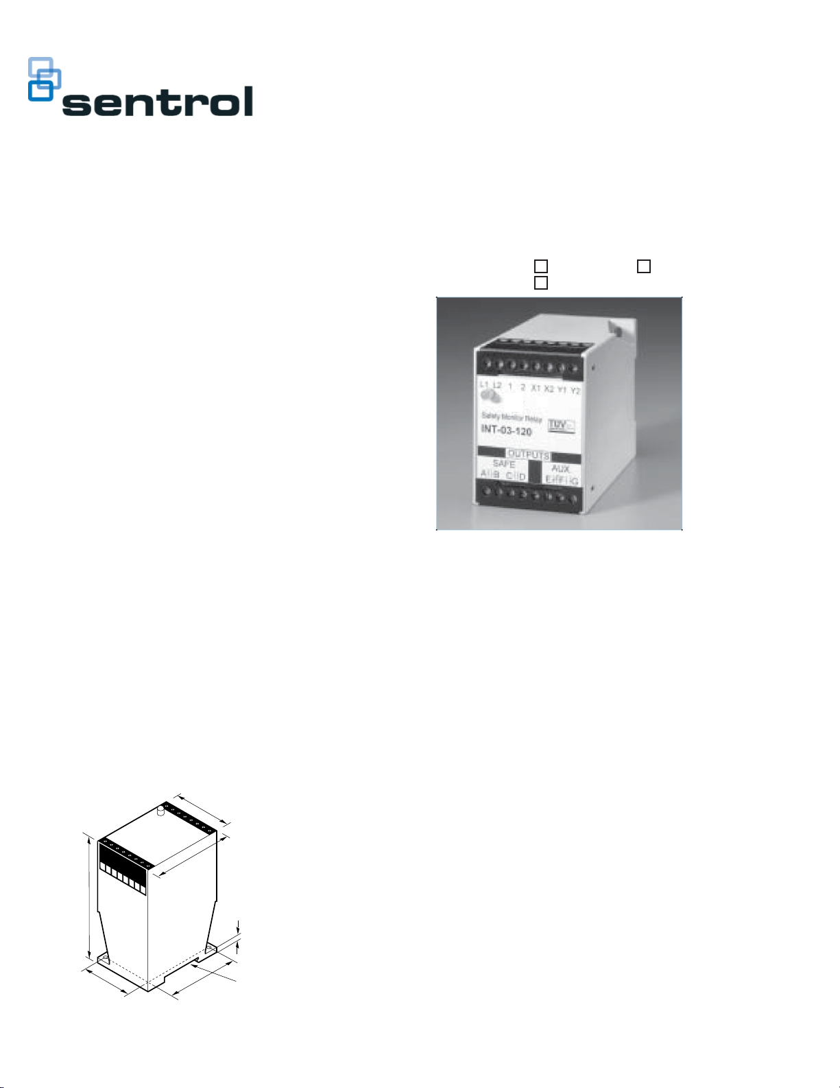
Description
The INT-03-024 or INT-03-120 Safety Monitor Relay is intended for use as a part of a
safety circuit in guard interlock applications. It is a safety relay which uses positiveguided relays, configured for self-checking, to inhibit machine start-up in the event of
an internal component failure.
Both normally-open and normally-closed inputs are required. Multiple N.O. contacts
can be wired in series while multiple N.C. contacts can be wired in parallel. Upon
failure of either the N.O. or N.C. contact, the relay will turn off and prevent restart.
The INT-03 relay can also monitor contacts on external relays for controlling expansion
block relays (Sentrol INT-05 and INT-06).
TUV Notes:
1. Relay conforms to Pollution Degree II, meets EN1760-1:1998, and must be installed
in an IP54-type enclosure.
2. The wire insulation of connected devices must be rated for 250VAC. The relay meets
basic insulation requirements only.
3. Input devices must meet requirements of EN60947-5-1.
4. The relay must be connected to a primary disconnect device that meets the
requirements of EN60947-3.
5. System total response time must not exceed 200ms.
6. Controller meets IP20 and must be connected to safety category 4 mat or
sensing device.
7. Test system before operation and after machine maintenance. Controller does not
require maintenance.
8. The complete system should be tested weekly. If a fault occurs, contact
Sentrol Industrial.
Dimensions
2.17"
5.5cm
2.95"
7.5cm
4.53"
11.5cm
0.26"
0.66cm
INT Monitor Relay
INT-03-024
INT-03
INT-03-120
Installation
Guardswitch™ Inputs: Wire the GuardSwitches™ in series and in parallel as shown in
the wiring diagram. When first applying power to the GuardSwitch™ Monitor Relay,
with no jumper or button from Terminal 1 to Terminal 2, realy will not energize.
With a jumper installed from Terminal 1 to Terminal 2, relay energizes when all guards
are in place (autostart).
With a RESET button installed from Termainal 1 to Terminal 2, relay energizes after
all guards are in place and RESET button is pressed. The monitor contacts must also
be closed.
Authorized Outputs: The designer must perform a risk analysis and be aware of the
applicable safety standards of their machine. The designer has a choice of how to use
the output contacts. The output contacts can be used in combination with an
Emergency Stop Relay circuit with a “reset” function. (“The restoring of an interlocked
safeguard shall not initiate machine motion or operation where this can result in a
hazardous condition. IEC 204-1.) The reset circuit should not be wired to disconnect
power to the GuardSwitch Monitor Relay, or it will be difficult to distinguish between a
GuardSwitch failure and a normal reset function.
Input Power: The GuardSwitch Monitor Relay is available in either a 24 VDC or 120
VAC model. Make sure the correct model is used before applying power as shown in the
wiring diagram.
INT-03 __________
1.48"
3.75cm
2.46"
6.25cm
Slot for 35mm
DIN rail mount
Page 2
Typical Wiring Diagram
RESET
120 VAC
FUSE
L1 L2 1 2 X1 X2 Y1 Y2
–
+
Safety Monitor Relay
INT-03
SAFE AUX.
A
BCD
N.O. N.C.
OUTPUTS
EFG
INT03WIR
230 VAC
60 VDC
LOADS
120 VAC
30 VDC
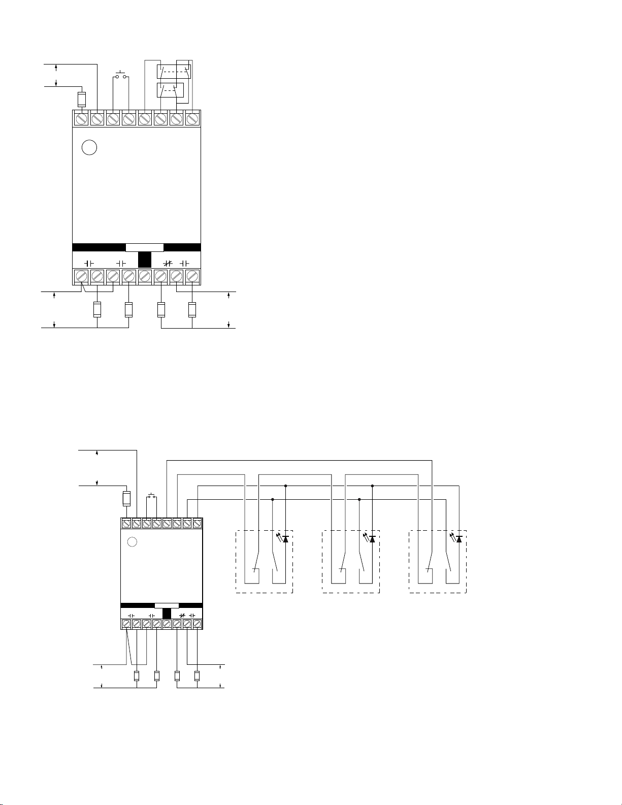
Multiple Switch Wiring Diagram
GuardSwitches™ are shown with the actuators in position—guard is closed. One 300-BT Series GuardSwitch™ is required for each safety gate. Up to 50 switches can be used with
INT-03. When using the BLT switch models, the voltage drop (30 ohms) must be taken into consideration.
(–)
INT-03-230: 230V AC
INT-03-120: 120V AC
INT-03-024: 24V DC
(+)
Required Fast or
Slow-Acting Fuse:
(250V, 5x20 mm F)
INT-03-230: 40mA
INT-03-120: 80mA
INT-03-024: 1/4A
RESET
L1 L2 1 2 X1 X2 Y1 Y2
–
+
Safety Monitor Relay
INT-03
SAFE AUX.
A
BCD
N.O. N.C.
OUTPUTS
EFG
W
B
H
L
T
K
*300-BLT-
*Or other DPST GuardSwitch
(See the 300-BT Series installation instructions)
Series Circuit
R
B
E
L
D
U
W
H
T
R
B
E
L
D
K
*300-BLT-
Parallel Circuit
B
L
U
W
H
T
R
B
E
L
D
K
*300-BLT-
B
L
U
Required Fast or SlowActing Fuses: 4A (250V,
5x20 mm F
230 VAC
60 VDC
LOADS
120 VAC
30 VDC
Note – The LED on the BLT model will be ON when the guard is open
Fuses: 1 A (250 v)
Multiple DPST GuardSwitches – Shown with actuators in position, all guards closed.
The L.E.D of the BLT model will be on when the guard is open. If multiple guards
are open, L.E.D will be dimmer. The maximum number of GuardSwitches that can
be used is 50, although troubleshooting and line resistance must be considered.
(Do not exceed 30 Ohms of combined contact and line resistance. Each GuardSwitch
will have less than 0.5 Ohms of resistance.)
Note: Only outputs AB and CD are safety outputs. Auxiliary form C output E, F, G may fail in an unsafe condition and should only be used for signaling.
Page 3

Category 4 Wiring Diagram
GuardSwitches™ are shown with the actuators in position—guard is closed. Inputs are shown with safety/guard in closed position. Two 300-B Series Guardswitch™ and one INT
relay are required for each safety gate.
(–)
INT-03-230: 230V AC
INT-03-120: 120V AC
INT-03-024: 24V DC
(+)
Required Fast or
Slow-Acting Fuse:
(250V, 5x20 mm F)
INT-03-230: 40mA
INT-03-120: 80mA
INT-03-024: 1/4A
RESET
L1 L2 1 2 X1 X2 Y1 Y2
–
+
N.O. N.C.
R
W
H
T
B
B
E
L
L
D
U
K
R
W
H
T
B
B
E
L
L
D
U
K
Required Fast or
Slow-Acting
Fuses: 4A (250V,
5x20 mm F
230 VAC
60 VDC
Safety Monitor Relay
INT-03
SAFE AUX.
A
BCD EFG
LOADS
OUTPUTS
120 VAC
30 VDC
*300-BLT-
*Or other DPST GuardSwitch
(See the 300-BT Series
installation instructions)
Note – The LED on the BLT model
will be ON when the guard is open
Fuses: 1A (250V)
*300-BLT-
Note: Only outputs AB and CD are safety outputs. Auxiliary form C output E, F, G may fail in an unsafe condition and should only be used for signaling.
Page 4

AUX Contacts
Power Guards E,G F,G
Off Open or Closed Closed Open
On Closed Closed Open
On Open Open Closed
European Directives
Machinery Directive (98/37/EEC)
Low Voltage Directive (73/23/EEC), LVD
Specific European Standards
EN60204-1 Safety of electrical equipment of industrial
machines: 1993
EN954-1 Risk Assessment Category 4 depending on wiring
method, See diagrams: 1997
EN50081-2 Electromagnetic Emissions: 1995
EN50082-2 Electromagnetic Immunity: 1995
Declaration of Conformity
available upon request.
IEC 664-1 Insulation requirements: 1992
IEC 68, part 2-1, 2-2, 2-3, 2-6, 2-14, 2-27, 2-30.
EN1760-1:1998
General Specifications
UL/CSA/TUV CSA submitted
Weight: INT-03-24: 9 oz.
INT-03-120/230: 15 oz.
Field wiring size 12 gauge max.
Temperature range 32°F to 149°F (-0°C to 65°C)
Relative humidity 30 to 95% non-condensing
Power Supply (+, - or L1, L2)
INT-03-024 24 VDC +/- 15% 100m
Required Fuse: 1/4A (250V, 5x20mm, F/T)
INT-03-120 120 VAC +10% -20%, 5VA, 50/60 Hz
Required Fuse: 80mA (250V, 5x20mm, F/T)
Control Inputs (X1, X2 & Y1, Y2 terminals)
Open-circuit voltage 24VDC
Closed-circuit current 24mA
Max. contact resistance 30 Ohms
Simultaneity 500 ms typical
Safe Outputs (A,B/C,D terminals)
Voltage 230 VAC/60VDC
Current 4A (resistive) each output
Resonse time < 100 ms
Fuse 4A, 250V, 5 x 20 mm
AUX. Signaling Outputs (E,F,G terminals)
Voltage 120 VAC/30VDC
Current 1A (resistive)
Note: Transient protection is required across the load when switching an
inductive load.
File E 122942
Ordering/Electrical Specifications
PART NUMBER POWER INPUT (L1.L2) INPUT FUSE REQUIRED
INT-03-024 24VDC +/-20% Fast acting 1/4A (250V, 5 x 20mm, F/T)
INT-03-120 120VAC +10%, -20%, 50/60 Hz, 5VA Fast acting 80mA (250V, 5 x 20mm, F/T)
 Loading...