

Page 1

E-RLY Analog Contact Relay Module
Installation Sheet
Description
The E-RLY Analog Contact Relay Module is an analog
addressable device that provides one Form C dry relay
contact. It can also be configured to provide polarity reversal of
its output. The module can be used to control external
appliances or shut down equipment.
The device address is set using the two rotary switches located
on the front of the module. One device address is required.
The module is wired according to its operation, as shown in
“Wiring” on page 2. The module is configured to operate as a
relay nonsilence device type from the factory. It can function as
either a control relay or polarity reversal relay, depending on
how it is wired.
Control relay function: Addressable device that provides one
Form C dry relay contact. The system firmware ensures that
the relay is in the proper state when powered up. Upon
command from the control panel, the E-RLY relay energizes.
Polarity reversal relay function: Addressable device that
provides polarity reversal of its output. The system firmware
ensures that the relay is in the proper state when powered up.
Upon command from the control panel, the E-RLY relay
energizes, reversing the polarity of its output.
Note: Additional device types are available through front panel
programming or the configuration utility. Refer to the applicable
control panel technical reference manual.
LED operation
The module provides a bicolor LED that shows its status.
Normal: Green LED flashes
Active: Red LED flashes
Installation
WARNING: Connecting a device that exceeds this module’s
pilot duty contact ratings may cause activation failure. This
module does not support capacitive loads. See “Specifications”
on page 4 for contact ratings.
Notes
• The module is shipped from the factory as an assembled
unit; it contains no user-serviceable parts and should not
be disassembled.
• This module will not operate without electrical power. As
fires frequently cause power interruption, you should
discuss further safeguards with your local fire protection
specialist.
• This module does not support conventional smoke
detectors.
• Install the module within the same room as the device it is
controlling.
To install the module:
1. Verify that all field wiring is free of opens, shorts, and
ground faults.
2. Wire the module in accordance with “Wiring” on page 2.
3. Set the module address as follows:
Use a screwdriver to adjust the two rotary switches on the
front of the module. Set the TENS rotary switch (0 through
12) for the 10s and 100s digit and the ONES rotary switch
for the 0 through 9 digit. For example: device address 21,
set the TENS rotary switch to 2 and set the ONES rotary
switch to 1.
Refer to “Specifications” on page 4 for available address
numbers.
4. Mount the module on the electrical box using screws
provided with the electrical box. See Figure 2.
5. Mount the wall plate on the module using #4-24 x
1/2 self-tapping screws.
© 2013 UTC Fire & Security. All rights reserved. 1 / 4 P/N 3101196 • REV 02 • ISS 28JAN13
Page 2
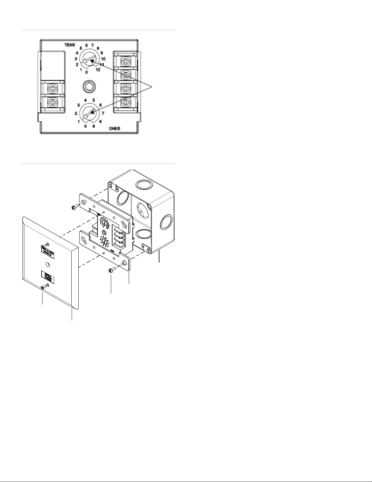
Figure 1: Module address
(1) Address switches
(1) #4-24 × 1/2 self-tapping screw
(2)
(3) Screw
(4) Module
(1)
(1)
(2)
(3)
(4)
(5)
• Only one conductor per terminal.
• The signaling line circuit (SLC) circuit is pow er-limited and
supervised.
• Refer to the panel documentation for SLC wiring
specifications.
To wire the module:
1. Verify that all field wiring is free of opens, shorts, and
ground faults.
2. Make all wiring connections using Figure 3 or Figure 4
according to the desired function. Observe polarity of the
wires as shown in the diagrams.
Figure 2: Module ins t a lla tion
Wall plate
Wiring
Wire in accordance with applicable requirements of the latest
editions of the local codes and standards and the local
authority having jurisdiction.
Note: When stripping wire ends, exposing more wire may
cause a ground fault; exposing less wire may result in a faulty
connection.
Strip 1/4 in. (about 6 mm) from the ends of all w ir es that
connect to the terminal block of the module.
Notes
2 / 4 P/N 3101196 • REV 02 • ISS 28JAN13
(5) Compatible electrical box
Page 3

Figure 3: Control relay function
(1) Normally closed contact (NC)
(2)
(3)
(4)
Use type FPL, FPLR, FPLP, or permitted substitute cables,
limited cable conductors extending beyond
(1) Normal
(2)
(3)
(4)
(5)
— or —
Use type FPL, FPLR, FPLP, or permitted substitute cables,
limited cable conductors extending beyond
TB2
TB1
(5)
(4)
(2)
(3)
(1)
(+)
( )
(6)
(7)
(8)
TB2
TB1
(6)
(5)
(2)(1)
(+)
( )
(7)
(8)
(3)
(4)
Normally open contact (NO)
Common contact
Power-limited unless connected to a nonpower-limited source. If
the source is nonpower-limited, eliminate the power-limited mark
and maintain a minimum of 0.25 in. (6.4 mm) space from powerlimited wiring. For other mounting methods, see enclosure and
bracket installation sheets to maintain separation of powerlimited and nonpower-limited wiring. The wire size must be
capable of handling fault current from nonpower-limited source.
— or —
provided these powerthe jacket are separated by a minimum of 0.2 5 in. (6.4 mm)
space or by a nonconductive sleeve or nonconductive barrier
from all other conductors. Refer to the NFPA 70 National
Electrical Code for more details.
(5) All wiring is power-limited and supervised
(6) Signaling line circuit (SLC) from previous device
(7) Signaling line circuit (SLC) to next device
(8) Not used
Figure 4: Polarity reversal relay function
Active
Power out
Power in
Power-limited unless connected to a nonpower-limited source. If
the source is nonpower-limited, eliminate the power-limited mark
and maintain a minimum of 0.25 in. (6.4 mm) space from powerlimited wiring. For other mounting methods, see enclosure and
bracket installation sheets to maintain separation of powerlimited and nonpower-limited wiring. The wire size must be
capable of handling fault current from nonpower-limited source.
P/N 3101196 • REV 02 • ISS 28JAN13 3 / 4
provided these power-
the jacket are separated by a minimum of 0.25 in. (6.4 mm)
space or by a nonconductive sleeve or nonconductive barrier
from all other conductors. Refer to the NFPA 70 National
Electrical Code for more details.
(6) All wiring is power-limited and supervised
(7) Signaling line circuit (SLC) from previous device
(8) Signaling line circuit (SLC) to next device
Page 4

Specifications
Communication line voltage
Current
Contact ratings (pilot duty)
0.5 A resistive load 60 W or 62.5 VA
Relay type
Ground fault
Compatible electrical boxes
Wire size
Operating environment
Storage temperature range
Module address
Manufacturer
Year of
manufacture
North American
standards
FCC compliance
Standby
Activated
30 VDC
125 VAC
Form C, programmable
impedance 10 kΩ
Temperature
Relative humidity
Maximum 20.6 V peak-to-peak
125 µA
125 µA
2 A
max.
4 inch square, 2-1/2 in. (64 mm)
deep single-gang box
4 inch square, 2-1/2 in. (64 mm)
deep double-gang box
Standard 4 in. square,
1-1/2 in. (38 mm) deep box
12, 14, 16, or 18 AWG wire (2.5,
1.5, 1.0, or 0.75 mm
and 18 AWG are preferred)
32 to 120°F (0 to 49°C)
0 to 93%, noncondensing
–4 to 140°F (–20 to 60°C)
01 to 64 (64 point control panel)
01 to 127 (127 point control panel)
2
) (Sizes 16
Regulatory information
Edwards, A Division of UTC Fire & Security
Americas Corporation, Inc.
8985 Town Center Parkway, Bradenton, FL
34202, USA
The first two digits of the DATE MFG number
(located on the product identification label) are
the year of manufacture.
CAN/ULC-S527, UL 864
This device complies with part 15 of the FCC
Rules. Operation is subject to the following two
conditions: (1) This device may not cause
harmful interference, and (2) this device must
accept any interference received, including
interference that may cause undesired operation.
Contact information
For contact information, see www.edwardssignaling.com.
4 / 4 P/N 3101196 • REV 02 • ISS 28JAN13
 Loading...