

Page 1

JP3
3 2 1
Settin
1
2
LED
Power LED
Flashes intermittently when the detector is in
Alarm/active LED
E-PDD Duct Smoke Detector Installation Sheet
Operation
The duct smoke detector's primary purpose is to provide early
warning of an impending fire and shut down the HVAC unit in
order to prevent smoke from circulating throughout the
building. The duct smoke detector is designed for use in duct
applications where temperatures can exceed standard detector
capabilities.
Air is introduced to the duct smoke detector's sensing chamber
through a sampling tube that extends into the HVAC duct and
is directed back into the ventilation system through an exhaust
tube. The difference in air pressure between the two tubes
pulls the sampled air through the sensing chamber. When a
sufficient amount of smoke is detected in the sensing cham ber,
the duct smoke detector notifies the fire alarm control panel.
The device address is set using the two rotary switches located
on the front of the unit. One device address is required.
The detector is capable of performing comprehensive selfdiagnostics and storing the results.
In installations where the duct smoke detector’s controls and
indicators are hidden from view, a remote test station or an
LED indicator can be connected to the detector to provide
these functions.
Jumper setting operation
The following jumper settings determine the operation of the
detector.
Figure 1: Jumper setting
LED operation
The detector provides two LEDs, visible from the front side of
the detector, that show its status.
Description
Off when the detector is in the alarm state
the normal state
Indicates the detector is in the alarm/active
state as follows:
Flashes at a continuous rate if the first
detector is in alarm/active
Flashes intermittently if not the first detector
in alarm/active
Installation
WARNINGS
• The duct smoke detector is not intended as a substitute for
open area protection.
• This detector will not operate without electrical power. As
fires frequently cause power interruption, you should
discuss further safeguards with your local fire protection
specialist.
• The duct smoke detector will not operate as designed
outside of the listed electrical and environmental
specifications.
Table 1:Jumper settings
g Operation Description
-2 Alarm
-3 Supervisory
© 2013 UTC Fire & Security. All rights reserved. 1 / 6 P/N 3101210 • REV 02 • ISS 28JAN13
Factory Default: Configures the detector
for alarm latching operation
Configures the detector for supervisory
operation
• The duct smoke detector will not sense smoke unless the
ventilation system is operating and the sensor’s cover is
properly installed.
• The duct smoke detector may not operate as designed
unless installed in accordance with these instru ctio ns and
all applicable national and local codes as determined by
the local authority having jurisdiction.
Note: Read these instructions thoroughly before installing. In
addition to this document, important infor mation can be found
in Technical Bulletin P/N 3101212.
Page 2
Installation guidelines
Model
SD
SD
SD
SD
SD
SD
SD
SD
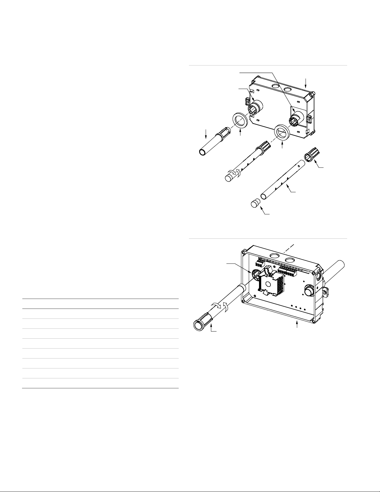
Detector
Sampling tube
socket
Exhaust tube
Thick
gasket
Thin
gasket
Exhaust tube
socket
Coupling
Sampling tube
(ordered separately)
Plug
Sampling tube
connector
Sampling tube
(fully assembled)
Detector
To ensure correct operation, install the duct detector using the
following guidelines:
• Install the duct smoke detector on a flat section of HVAC
duct between six and ten duct widths from any bends or
obstructions.
• Install supply-side detectors at a point downstream from
the supply fan and after the air filter.
• Install return-side detectors at a point before the return air
stream is diluted by outside air.
Verify the duct air velocity
In order to verify airflow direction and velocity, air must be
moving through the HVAC system.
To verify the duct air velocity:
1. Drill a small hole at the point where the duct smoke
detector is being installed.
2. Using the SD-VTK Air Velocity Test Kit and a suitable air
velocity meter, verify that the air velocity in the HVAC duct
falls within the specified operating range of the detector
and note which direction the air flows.
3. If the air velocity does not fall within the specified rang e,
relocate the detector and seal the hole in the HVAC duct.
Refer to Technical Bulletin P/N 3101212 for additional
information pertaining to installation locations.
Select the appropriate sampling tube:
3. The sampling tube is normally installed from the rear, but it
can also be installed from the front of the detector as
shown in Figure 3. This method requires that you remove
the detector cover.
Figure 2: Duct detector assembly
Figure 3: Sampling tube installa t io n
• Select a sampling tube that extends at least two-thirds
• For duct widths greater than 36 inches, use a sampling
• Sampling tubes are available in the following lengths:
To assemble the detector:
1. Assemble the duct smoke detector as shown in Figure 2.
2. Rotate the air sampling tube so the inlet holes face the
across the width of the duct.
tube that is longer than the width of the duct.
Description
-T8 8-inch sampling tube
-T18 18-inch sampling tube
-T24 24-inch sampling tube
-T36 36-inch sampling tube
-T42 48-inch sampling tube
-T60 60-inch sampling tube
-T78 78-inch sampling tube
-T120 120-inch sampling tube
direction of airflow.
To install the detector:
1. Attach the drill template to the HVAC duct at desired
mounting location.
2. Drill (or punch) the mounting holes where indicated.
Note: Sampling tubes longer than 36 inches must be
supported at both ends of the duct.
3. If using an air sampling tube that is longer than the width
of the duct, drill a 3/4-inch hole on the opposite side of the
duct for tube to pass through.
4. Remove any rough edges from the holes.
2 / 6 P/N 3101210 • REV 02 • ISS 28JAN13
Page 3

5. Mount the duct smoke detector on the HVAC duct and
HVAC duct
Airflow
Sampling
tube
Detector
#10 sheet metal screw (2X)
HVAC
duct
Sampling
tube
Exhaust tube
Plug
Detector
Sealant
Airflow
36 in≥
0
1
2
3
4
5
6
12
11
10
9
8
7
0
9
1
2
3
4
5
6
7
8
Insert screwdriver here
secure it using two sheet metal screws provided.
6. If using an air sampling tube that is longer than the width
of the duct, cut the tube so that approximately one inch of
the tube extends through the duct. Seal the opening
around the tube with an approved duct sealant as shown
in Figure 4.
Use a screwdriver to adjust the two rotary switches on the
front of the module. Set the TENS rotary switch (0 through
12) for the 10s and 100s digit and the ONES rotary switch
for the 0 through 9 digit. For example: device address 21,
set TENS rotary switch to 2 and set the ONES rotary
switch to 1.
Refer to “Specification s” for availa ble addr e ss number s.
Figure 4: Duct detector installation
Figure 5: Sampling tube support
Figure 6: Duct detector address
10. Set jumper JP3 to appropriate position. Refer to
“Operation.”
11. Verify the air pressure differential value falls within the
specified operating range of the detector in accordance
with procedures specified in “Maintenance and testing.”
12. After completing installation of the duct smoke detector,
test the detector to ensure it is operating correctly in
accordance with procedures specified in “Maintenance
and testing.”
Maintenance and testin g
Verify the air pressure differential:
In order to verify air pres sure differential, air must be moving
through the HVAC system.
7. Verify that all field wiring is free of opens, shorts, and
ground faults.
8. Make all wiring connections as shown in “Wiring.”
9. Set the module address as follows:
To verify the air pressure differential:
1. Connect a suitable air pressure differential meter to the
sampling tube and exhaust tube openings as shown in
Figure 7.
2. Verify that the air pressure differential measured falls
within the specified operating range of the detector.
3. If the air pressure differential measured does not fall within
the specified operating range of the detector, make sure
the sampling tube air holes are not obstructed and are
facing the HVAC system airflow.
P/N 3101210 • REV 02 • ISS 28JAN13 3 / 6
Page 4

Figure 7: Air pressure differential
Airflow
Sampling tube
opening
Exhaust tube
opening
HVAC duct
Sampling
tube
Air pressure
differential
meter
Model
E
Airflow
HVAC duct
Sampling
tube
Retainer
clip
Optic
plate
Optic
housing
Detector
housing
To clean the duct smoke detector:
1. Disable the detector/zone to prevent false alarms.
2. Remove the detector’s cover then power down the
detector by disconnecting the SLC wiring.
3. Using a vacuum cleaner, clean compressed air, or a soft
bristle brush, remove loose dirt and debris from inside the
detector housing and cover.
4. Remove dirt and other contaminants from the gasket on
the detector’s cover using isopropyl alcohol and a lint-free
cloth.
5. Squeeze the retainer clips on both sides of the optic
housing then lift the housing away from the printed circuit
board.
6. Gently remove dirt and debris from around the optic plate
and inside the optic housing.
7. Replace the optic housing and detector cover, and then
connect the SLC wiring.
8. Test the detector and verify sensitivity. For details, refer to
Technical Bulletin P/N 3101212.
Figure 8: Duct detector cleaning
Testing the duct smoke detector
After completing installation of the duct smoke detector, test
the detector to ensure it is operating correctly prior to leaving
the site. For details, refer to Technical Bulletin P/N 3101212.
Replacement parts
The following table lists the replacement parts for the duct
smoke detector.
Description
-SDPCB PCB replacement kit for duct smoke detector
Cleaning the duct smoke detector
Clean the duct smoke detector when it becomes 80% to 99%
dirty or sooner if conditions warrant.
Caution: Before cleaning the duct smoke detector, notify the
proper authorities that the fire alarm system is under goi ng
maintenance and take steps to prevent the control panel from
responding to a false alarm.
Wiring
Wire in accordance with NFPA 72 and CAN/ULC-S524. Be
sure to observe the polarity of the terminals on the terminal
block as shown in Figure 9.
4 / 6 P/N 3101210 • REV 02 • ISS 28JAN13
Page 5

Figure 9: Duct detector wiring
11 10 9
Auxiliary
equipment [2]
Power indicator
Alarm indicator
Remote test
station [1]
+
−
Remote
alarm/active
indicator [1]
or
Alarm/active
Alarm/active
Test
8 7
6 5 4 3 2 1
SLC( )−
SLC( )−
SLC( )+
SLC( )
+
1
2
3
4
JP3
3 2 1
0
1
2
3
4
5
6
12
11
10
9
8
7
0
9
1
2
3
4
5
6
7
8
Notes
[1] No more than one remote test station or LED indicator can be connected to the detector at the same time. Wiring is unsupervised. Maximum
wire resistance is 10 ohms per wire.
[2] Power-limited when connected to a power-limited source. If connected to a nonpower-limited source, all power-limited wiring in box must use
FPL, FPLR, or FPLP cable or equivalent per NEC.
P/N 3101210 • REV 02 • ISS 28JAN13 5 / 6
Page 6

Specifications
Com
Operating current
Common alarm
relay/auxiliary equipment
Air velocit
Air pressure differential
Smoke sensitivity range
Smoke detection method
Alarm test response time
Dimensions
Operating environment
Wire size
Detector address
Accessories
munication line voltage Maximum 20 V peak-to-peak
Normal
Alarm
Inrush
y 100 to 4,000 ft./min
8.70 x 5.45 x 1.90 inches
Temperature
Humidity
14 to 22 AWG wire
01 to 64 (64 point control panel)
SD-TRM
SD-TRK
SD-MAG
SD-VTK
R-LED
45 µA
45 µA
1 mA
Unsupervised and power-limited
Quantity: 1
Type: Form C
Ratings: 2.0 A at 30 VDC (resistive)
0.005 to 1.00 inches of water
0.79 to 2.46%/ft. obscuration
Photoelectric (light scattering
principle)
5 seconds
32 to 122°F (0 to 50°C)
0 to 93% RH, noncondensing
01 to 127 (127 point control panel)
Remote test-reset station, magnetic
Remote test-reset station, keyed
Test magnet kit
Air velocity test kit
Remote LED alarm indicator
6 / 6 P/N 3101210 • REV 02 • ISS 28JAN13
 Loading...