

Page 1

eFSA64 and eFSA250
Technical Reference Manual
P/N 3101202-EN • REV 06 • ISS 02MAY13
Page 2

Copyright
©
2013 UTC Fire & Security Americas Corporation, Inc.
Trademarks and
patents
The
Fire & Security
Other trade names used in this document may be trademarks or
registered trademarks of the manufacturers or vendors of the
respective products.
Manufacturer
Edwards, A Division of UTC
Americas
8985 Town Center Parkway, Bradenton, FL 34202, USA
Authorized EU manufacturing representative:
UTC Fire & Security B.V.
Kelvinstraat 7, 6003 DH Weert,
FCC compliance
Class A: This equipment has been tested and found to comply with
the limits for a Class A digital device, pursuant to part 15 of the FCC
Rules. These limits are designed to provide reasonable protection
against harmful interfe
commercial environment. This equipment generates, uses, and can
radiate radio frequency energy and, if not installed and used in
accordance with the instruction manual, may cause harmful
interference to radio communications. Operation of this equipment in
a residential area is likely to cause harmful interference in which
case the user will be required to correct the interference at his own
expense.
European Union
directives
1999/5/EC (R&TTE directive):
declares that this device is in compliance with the essential
requirements and other relevant provisions of Directive 1999/5/EC.
2002/96/EC (WEEE directive):
cannot be disposed of as unsorted municipal
Union. For proper recycling, return this product to your local supplier
upon the purchase of equivalent new equipment, or dispose of it at
designated collection points. For more information see:
www.recyclethis.info.
2006/66/EC (
This product contains a battery that
cannot be disposed of as unsorted municipal waste in the European
Union. See the product documentation for specific battery
information. The battery is marked with this symbol, which may
include lett
(Hg). For proper recycling, return the battery to your supplier or to a
designated collection point. For more information see:
www.recyclethis.info.
Contact information
For contact information, see w
E-FSA64 and E-FSA250 name and logo are trademarks of UTC
Americas Corporation, Inc.
Fire & Security
Corporation, Inc.
Netherlands
rence when the equipment is operated in a
battery directive):
ering to indicate cadmium (Cd), lead (Pb), or mercury
Hereby, UTC Fire & Security
Products marked with this symbol
waste in the European
ww.edwardssignaling.com.
Page 3

Content
Important information v
Minimum system requirements viii
To get started viii
Chapter 1 Installation and wiring 1
Panel backbox installation 2
Panel electronics installation 3
Panel backbox wire routing 5
AC power wiring 5
Panel low voltage wiring 6
Battery wiring (TB8) 7
Notification appliance circuit wiring (TB2) 8
Addressable device loop wiring 11
Alarm, trouble, and supervisory relay wiring (TB3) 13
Remote annunciator wiring (TB4) 15
Auxiliary/smoke power output wiring 16
SA-DACT wiring 19
SA-232 wiring 21
SA-CLA wiring 23
SA-ETH wiring 24
CTM module wiring 25
RPM module wiring 27
Chapter 2 Front panel programming 29
UL 864 programming requirements 31
Getting started 32
Device type descriptions 43
Displaying the Program menu 48
Setting the time and date 48
Setting daylight saving time 49
Changing the passwords 51
Restoring the factory default settings 51
Setting up the programmable keys 52
Clearing the event history log 56
Updating the firmware 57
Restarting the panel 60
Enabling RS232 communication 60
Auto programming the panel 61
E-FSA64 and E-FSA250 Technical Reference Manual i
Page 4

Performing incremental programming 69
Adding and removing devices from programmed systems 73
Advanced programming 84
Chapter 3 System operation 137
Operation overview 139
LCD display screen 140
System LEDs 144
LED display expander LEDs 144
Control buttons 145
Component descriptions 150
Events with event messages 151
Event ID numbers and descriptions 154
Viewing event details 160
Resetting the panel 160
Silencing panel and annunciator buzzers 161
Silencing notification appliances 161
Conducting a lamp test 163
Activating and restoring output devices 163
Unlatching latched output devices 164
Activating and restoring panel NACs 165
Activating and restoring sensor bypass 166
Activating and restoring gas accelerated response 168
Disabling and enabling devices 169
Disabling and enabling zones 170
Disabling and enabling panel events 172
Disabling and enabling loop events 173
Disabling and enabling panel NACs 175
Disabling and enabling the dialer and network 176
Initiating a fire drill 176
Conducting a walk test 177
Chapter 4 Reports 181
Basic steps for viewing and printing reports 182
History report 182
Walk Test report 184
Device Maintenance report 184
System Status report 185
Correlation Groups report 186
Correlation Group Configuration report 186
Zone report 187
System Configuration report 187
Internal Status report 188
ii E-FSA64 and E-FSA250 Technical Reference Manual
Page 5

Device Details report 189
Diagnostics reports 189
Internal Fault report 191
Canceling a report 192
Chapter 5 Diagnostics, maintenance, and testing 193
Preventive maintenance schedule 194
Fast ground check 194
Recalibrate device 195
Flash device LED 195
Loop comm check 196
Control panel testing 197
Testing a device (test fire) 198
SA-DACT testing 199
Conducting a lamp test 200
Starting and stopping a walk test 201
Using HyperTerminal 203
Replacing a device in alarm 204
Appendix A Panel specifications 207
Control panel specifications 208
Appendix B Worksheets 211
Battery calculation worksheet 212
Notification appliance circuit calculations worksheet 215
Notification appliance voltage drop calculation worksheet 221
Device loop maximum wire length worksheet 222
Correlation groups worksheet 227
Device settings worksheet 228
Loop worksheet 230
Panel configuration worksheet 231
Panel operation worksheet 234
Zone settings worksheet 235
Appendix C Front panel menu flowcharts 237
Main menu 238
Reports menu (1 of 2) 239
Reports menu (2 of 2) 240
Test menu 241
Control menu 242
Program menu 243
Program: Programmable Keys menu 244
Auto Program menu 245
Advanced Program: Loop Configuration menu 246
E-FSA64 and E-FSA250 Technical Reference Manual iii
Page 6

Advanced Program: Correlation Groups menu 247
Advanced Program: Loop Configuration — Device menu 248
Advanced Program: Panel Configuration menu 249
Advanced Program: Panel Event Correlations menu 250
Advanced Program: Panel Configuration — CMS Device
menu 251
Advanced Program: Panel Operation menu 252
Advanced Program: Panel Events menu 253
Advanced Program: Loop Events menu 254
Advanced Program: Unconfigured Alarm menu 255
Advanced Program: Common Trouble menu 255
Auto Program command menu flow 256
Incremental Program menu 257
Diagnostics menu 258
Appendix D Applications 259
Local alarm signaling applications 259
Correlated zone and system alarm signaling applications 261
In-suite signal silence applications 265
Index 269
iv E-FSA64 and E-FSA250 Technical Reference Manual
Page 7

Important information
Limitation of liability
This product has been designed to meet the requirements of NFPA 72 National
Fire Alarm and Signaling Code, UL 864 Standard for Control Units and
Accessories for Fire Alarm Systems, and ULC-S527 Standard for Control Units
for Fire Alarm Systems. Installation in accordance with this manual, applicable
codes, and the instructions of the authority having jurisdiction (AHJ) is
mandatory. UTCD Fire & Security shall not under any circumstances be liable for
any incidental or consequential damages arising from loss of property or other
damages or losses owing to the failure of UTC Fire & Security products beyond
the cost of repair or replacement of any defective products. UTC Fire & Security
reserves the right to make product improvements and change product
specifications at any time.
While every precaution has been taken during the preparation of this manual to
ensure the accuracy of its contents, UTC Fire & Security assumes no
responsibility for errors or omissions.
FCC compliance statement
This equipment can generate and radiate radio frequency energy. If the
equipment is not installed in accordance with this manual, it may cause
interference to radio communications. This equipment has been tested and found
to comply with the limits for Class A computing devices pursuant to Subpart B of
Part 15 of the FCC Rules. These rules are designed to provide reasonable
protection against such interference when this equipment is operated in a
commercial environment. Operation of this equipment is likely to cause
interference, in which case the user, at his own expense, will be required to take
whatever measures may be required to correct the interference.
SA-DACT FCC information
Cautions
• To ensure proper operation, this dialer must be installed according to the
enclosed installation instructions. To verify that the dialer is operating properly
and can successfully report an alarm, it must be tested immediately after
installation, and periodically thereafter, according to the enclosed test
instructions.
E-FSA64 and E-FSA250 Technical Reference Manual v
Page 8

• In order for the dialer to be able to seize the phone line to report an alarm or
other event when other customer equipment (telephone, answering system,
computer modem, etc.) connected to the same line is in use, the dialer must
be connected to a properly installed RJ-31X jack. The RJ-31X jack must be
connected in series with, and ahead of, all other equipment attached to the
same phone line. Series installation of an RJ-31X jack is depicted in the
wiring diagram. If you have any questions concerning these instructions, you
should consult your telephone company or a qualified installer.
Testing
When programming emergency numbers or making test calls to emergency
numbers, remain on the line and briefly explain to the dispatcher the reason for
the call. Perform programming and testing activities in the off-peak hours, such
as early morning or late evenings.
Compliance
• This dialer complies with Part 68 of the FCC rules and the requirements
adopted by the Administrative Council for Terminal Attachments (ACTA). A
label attached to the dialer contains, among other information, a product
identifier in the format US:AAAEQ##TXXXX. If requested, this information
must be provided to the telephone company.
• The plug and jack used to connect the dialer to the premises wiring and
telephone network must comply with the applicable FCC Part 68 rules and
requirements adopted by ACTA. The dialer must be connected to a compliant
RJ-31X or RJ-38X jack using a compliant cord. If a modular telephone cord is
supplied with the dialer, it is designed to meet these requirements. See
installation instructions for details.
• A ringer equivalence number (REN) is used to determine how many devices
you can connect to a telephone line. If the total REN value for all devices
connected on a telephone line exceeds that allowed by the telephone
company, the devices may not ring on an incoming call. In most (but not all)
areas the total REN value should not exceed 5.0. To be certain of the total
REN value allowed on a telephone line, contact the local telephone company.
• For products approved after July 23, 2001, the REN is part of the product
identifier in the format US:AAAEQ##TXXXX. The digits ## represent the REN
without a decimal point. Example: 03 is an REN of 0.3. For earlier products
the REN is listed separately.
vi E-FSA64 and E-FSA250 Technical Reference Manual
Page 9

• If the dialer is harming the telephone network, the telephone company will
notify you in advance that temporary discontinuance of service may be
required. If advance notice isn’t practical, the telephone company will notify
you as soon as possible. You will also be advised of your right to file a
complaint with the FCC, if you believe it is necessary.
• The telephone company may make changes to its facilities, equipment,
operations, or procedures that could affect the operation of the dialer. If this
happens, the telephone company will provide advance notice in order for you
to make necessary modifications to maintain uninterrupted service.
• If you are experiencing problems with the dialer, contact the manufacturer for
repair or warranty information. If the dialer is harming the telephone network,
the telephone company may request that you disconnect the dialer until the
problem is resolved.
• The dialer contains no user serviceable parts. In case of defects, return the
dialer for repair.
• You may not connect the dialer to a public coin phone or a party line service
provided by the telephone company.
Industry Canada information
The Industry Canada label identifies certified equipment. This certification means
that the equipment meets certain telecommunications network protective,
operational, and safety requirements. Industry Canada does not guarantee the
equipment will operate to the user’s satisfaction.
Before installing this equipment, users should ensure that it is permissible to be
connected to the facilities of the local telecommunications company. The
equipment must also be installed using an acceptable method of connection. The
customer should be aware that compliance with the above conditions may not
prevent degradation of service in some situations.
Repairs to certified equipment should be made by an authorized Canadian
maintenance facility designated by the supplier. Any repairs or alterations made
by the user to this equipment, or equipment malfunctions, may give the
telecommunications company cause to request the user disconnect the
equipment.
Caution: Users should not attempt to make connections themselves, but should
contact the appropriate electrical inspection authority, or electrician, as
appropriate.
E-FSA64 and E-FSA250 Technical Reference Manual vii
Page 10

System
Protected Premises (Local) Fire Alarm System
Auxiliary Fire Alarm System, Local Energy Type
Remote Supervising Station F
Central Station Fire Alarm System
Users should ensure for their own protection that the electrical ground
connections of the power utility, telephone lines, and internal metallic water pipe
system, if present, are connected together. This precaution may be particularly
important in rural areas.
Note: The Load Number (LN) assigned to each terminal device denotes the
percentage of the total load to be connected to a telephone loop that is used by
the device, to prevent overloading. The termination on a loop may consist of any
combination of devices subject only to the requirements that the sum of the Load
Numbers of all the devices does not exceed 100.
Minimum system requirements
The table below lists the minimum hardware requirements for each type of
system for which the control panel is listed.
Table 1: Minimum hardware requirements for applications
Equipment needed
Control panel
Appropriately sized batteries
Control panel
Appropriately sized batteries
CTM module
ire Alarm System Control panel
Appropriately sized batteries
SA-DACT or RPM module
Control panel
Appropriately sized batteries
SA-DACT or RPM module
To get started
If you are just starting out, follow the items in this checklist to prepare, install,
wire, and program your fire alarm control panel.
1. Prepare the site. Make sure the installation location is free from construction
dust and debris and extreme temperature ranges and humidity.
2. Unpack the equipment.
viii E-FSA64 and E-FSA250 Technical Reference Manual
Page 11

3. Install the panel backbox. See “Panel backbox installation” on page 2 for
backbox dimensions.
4. Install the panel electronics in the panel backbox. See “Panel electronics
installation” on page 3.
5. Remove the clear protective plastic from the front panel display.
6. Install the optional panel accessories. Refer to each component’s installation
sheet instructions.
7. Review Chapter 1 “Installation and wiring” starting on page 1.
WARNING: Make sure that the AC power circuit breaker is off before
connecting wires to the terminal block.
8. Connect the field wiring. Meter for opens, grounds, and shorts before
connecting.
9. Connect AC power and ground wiring. See “AC power wiring” on page 5. The
panel cannot be started on batteries only.
10. Connect panel low voltage wiring. See “Panel low voltage wiring” on page 6.
11. Turn on AC power.
12. Connect the batteries. See “Battery wiring (TB8)” on page 7.
13. Program the panel. See Chapter 2 “Front panel programming” on page 29. If
you are using the configuration utility, refer to the online help.
14. Test the system for proper operation.
E-FSA64 and E-FSA250 Technical Reference Manual ix
Page 12

x E-FSA64 and E-FSA250 Technical Reference Manual
Page 13

Chapter 1
Installation and wiring
Summary
This chapter covers all control panel wiring, such as AC power, NACs, device
loops, and battery wiring.
Content
Panel backbox installation 2
Panel electronics installation 3
Panel backbox wire routing 5
AC power wiring 5
Panel low voltage wiring 6
Battery wiring (TB8) 7
Notification appliance circuit wiring (TB2) 8
Addressable device loop wiring 11
Alarm, trouble, and supervisory relay wiring (TB3) 13
Remote annunciator wiring (TB4) 15
Auxiliary/smoke power output wiring 16
SA-DACT wiring 19
SA-232 wiring 21
SA-CLA wiring 23
SA-ETH wiring 24
Circuit specifications 25
CTM module wiring 25
RPM module wiring 27
E-FSA64 and E-FSA250 Technical Reference Manual 1
Page 14
Chapter 1: Installation and wiring
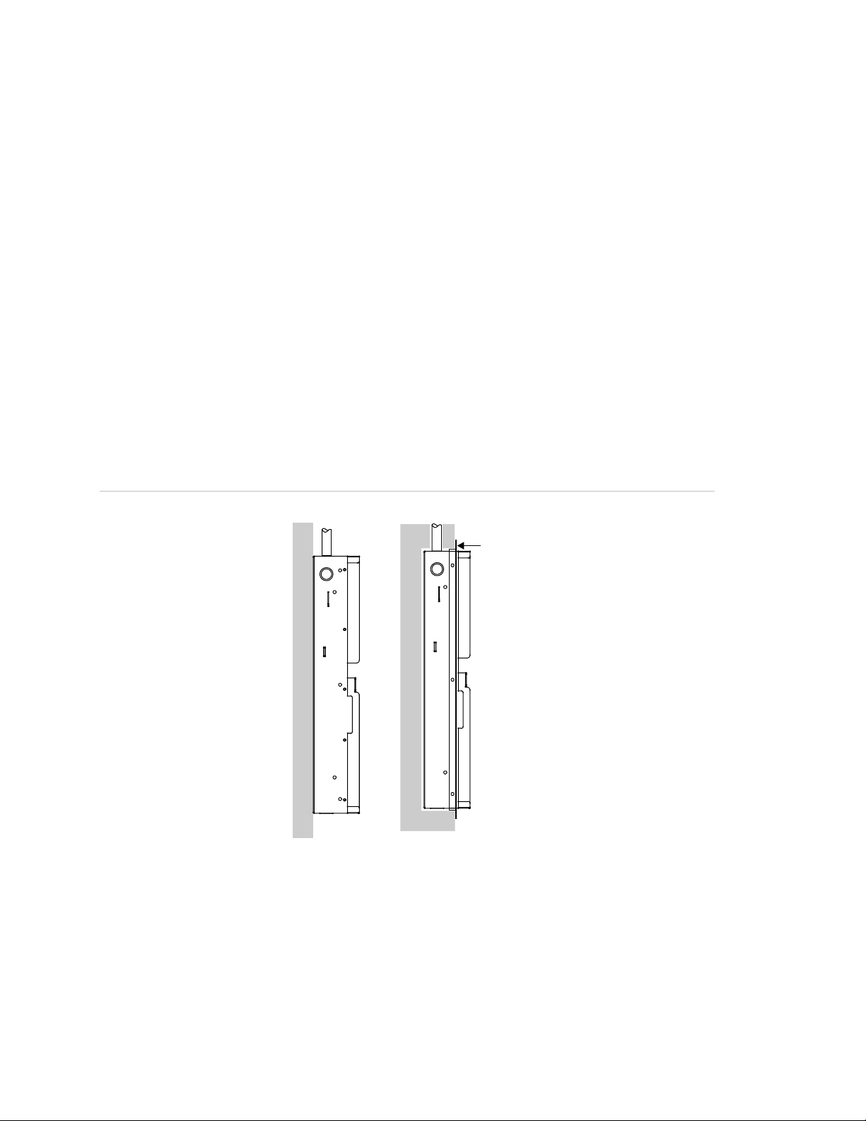
Surface mount Semiflush mount
Trim ring
Panel backbox installation
The panel backbox can be surfaced mounted or semiflush mounted.
To surface mount the panel backbox:
1. Position the panel backbox on the finished wall surface.
2. Fasten the panel backbox to the wall surface where indicated.
To semiflush mount the panel backbox:
1. Frame the interior wall (as required) to support the full weight of the backbox
and standby batteries.
2. Install a semiflush trim ring (optional) to the backbox.
3. Fasten the panel backbox to the framing studs where indicated.
Figure 1: Surface and semiflush mounting details
2 E-FSA64 and E-FSA250 Technical Reference Manual
Page 15
Chapter 1: Installation and wiring
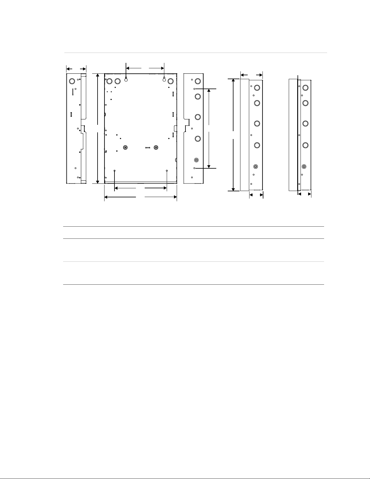
D5
Surface mounting holes
Backbox with
Backbox with door and
[1]
(1.9 cm) of trim to the top, bottom, and sides of the panel backbox.
Figure 2: Panel backbox, backbox with door, and backbox with door and trim ring attached
D2
D1
D3
Surface mounting holes
D6
door attached
D7
D4
D8
Semiflush mounting holes
D9
trim ring attached
D9
Table 2: Backbox and backbox with door dimensions (in. and cm)
Model D1 [1] D2 D3 D4 D5 [1] D6 D7 D8 D9
eFSA64 21.50
(54.6)
eFSA250 28.0
(71.1)
3.85
(9.8)
3.85
(9.8)
7.5
(19)
9.0
(22.8)
15.50
(39.4)
22.0
(55.8)
14.25
(36.2)
15.75
(40.0)
10.25
(26.0)
10.25
(26.0)
3.9
(9.9)
3.9
(9.9)
21.7
(55.1)
28.2
(71.6)
Add 1-1/2 in. (3.81 cm) to D1 and D5 dimensions for trim kit. The trim kit provides .75 inches
Panel electronics installation
To reduce possible damage to the panel’s electronics during backbox installation,
the electronics are packaged separately and must be installed in the panel
backbox. The electronics are shipped already mounted to a plastic backplane.
Note: Be sure that any possibility for construction damage and vandalism has
passed before installing the panel electronics.
2.7
(6.8)
2.7
(6.8)
E-FSA64 and E-FSA250 Technical Reference Manual 3
Page 16
Chapter 1: Installation and wiring
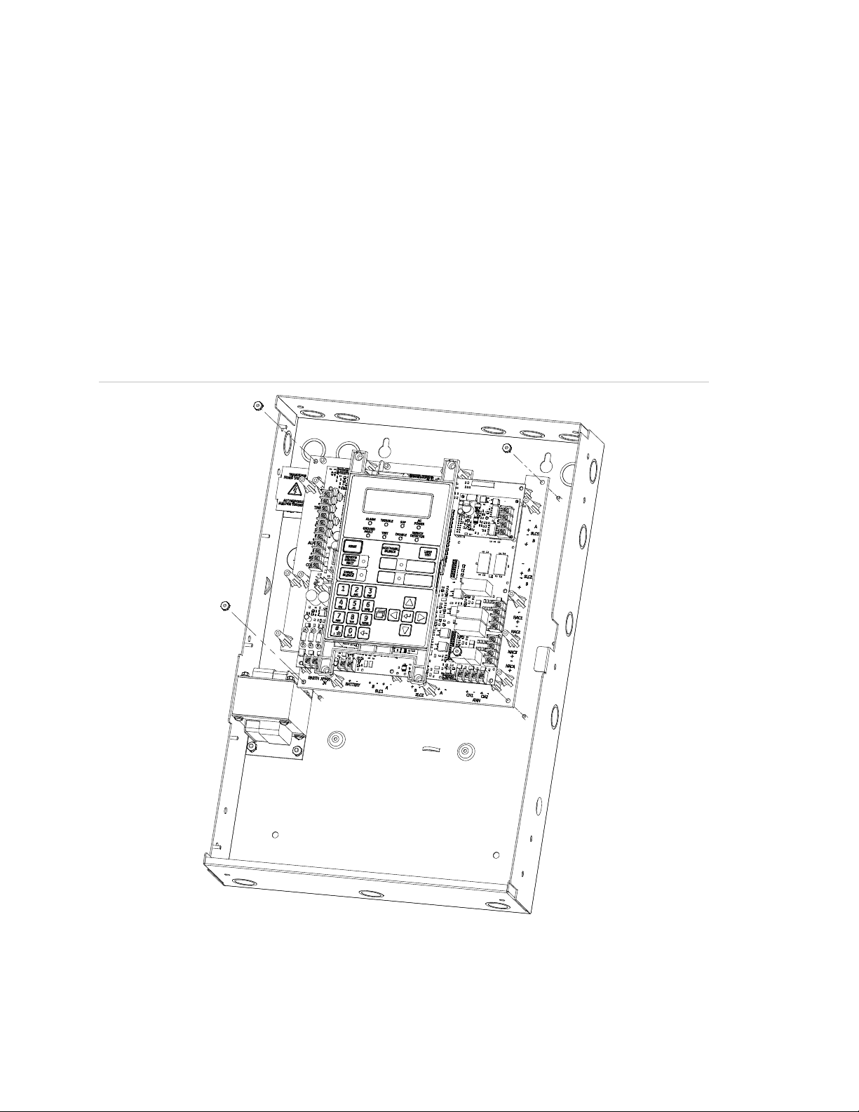
To install the panel electronics in the backbox:
1. Mount and connect the panel option modules (SA-DACT, SA-ETH, SA-232,
SA-CLA, and XAL127) to the main panel electronics or backplane.
2. Place the panel electronics in the panel backbox, so the four threaded studs
in the backbox protrude through the holes in the corners of the backplane.
Use the 10-24 nuts provided with the panel electronics to secure the
backplane.
3. Confirm that the AC is off or disconnected so that no current is flowing from
the AC terminal block. Connect the secondary wires from the transformer to
proper terminals.
Figure 3: Panel electronics installation
4 E-FSA64 and E-FSA250 Technical Reference Manual
Page 17
Chapter 1: Installation and wiring
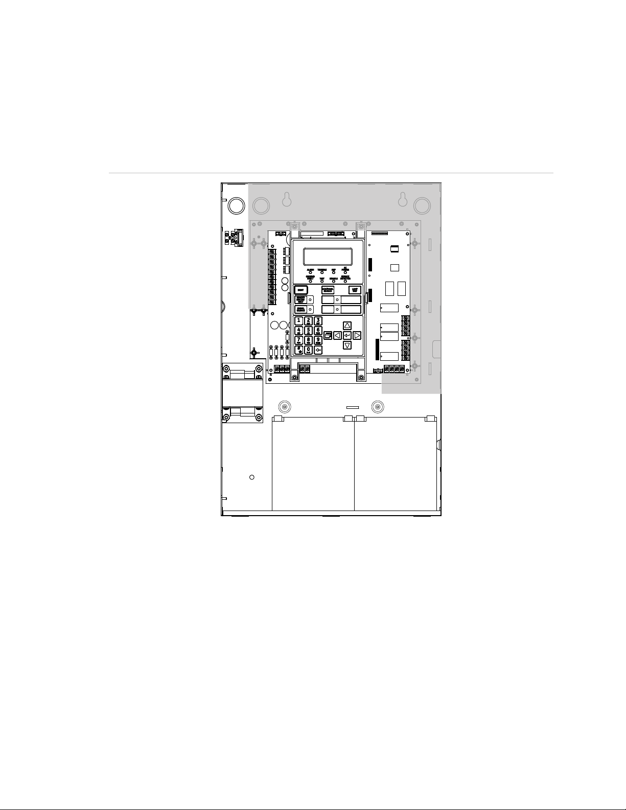
Panel backbox wire routing
Using the diagram below, keep power-limited wiring in the shaded area and
nonpower-limited wiring in the unshaded area at all times.
Figure 4: Panel backbox wire routing
00:00:00 01/01/07
[1]
,
[1] Power-limited only when connected to a power-limited source. If connected to a nonpower-
limited source, all wiring on terminal block TB3 must be NPFPL, NPFPLR, or NPFPLP rated
wire or equivalent, in accordance with the NFPA 70 National Electric Code and routed
separately from all power-limited wiring.
AC power wiring
Circuit specifications
• eFSA64 panel: 120 V, 60 Hz, 1.3 A or 230 V, 50/60 Hz,
0.62 A from dedicated branch supply
• eFSA250 panel: 120 V, 60 Hz, 2.0 A or 230 V, 50/60 Hz,
0.97 A from dedicated branch supply
E-FSA64 and E-FSA250 Technical Reference Manual 5
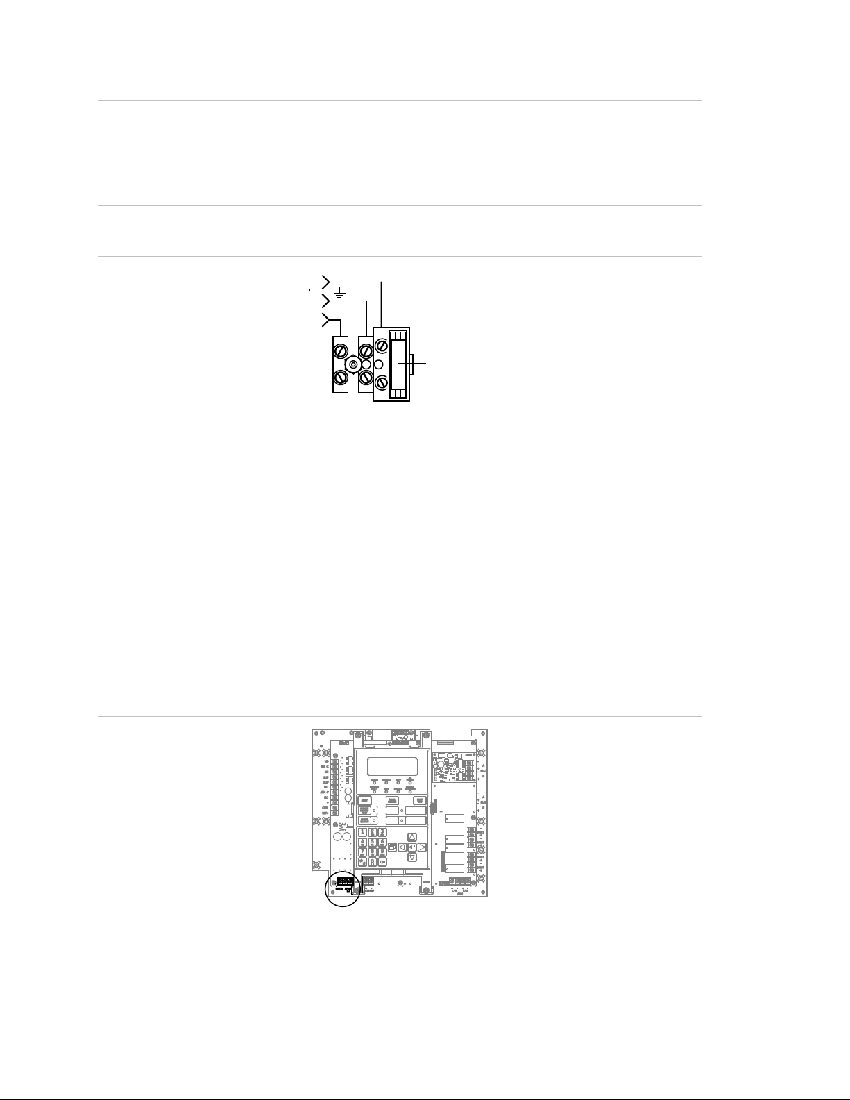
Page 18
Chapter 1: Installation and wiring
(Littlefuse P/N 218005)
L
EARTH GND
primary power connection
WARNING: Never replace the fuse while the circuit is energized. The
replacement fuse must be of equivalent size and type.
Caution: The middle connection (EARTH GND) on the terminal block makes a
mechanical connection to the chassis even with the ground wire removed.
Figure 5: AC power wiring
LINE
NEUTRAL
N
5 A, 250 V, SLO-BLO
120 or 230 VAC
Note: See “Component descriptions” on page 150 for the location of the wiring
block in the backbox.
Panel low voltage wiring
Circuit specifications
• Circuit voltage: 24 VAC
• All circuits are power-limited unless otherwise noted
Figure 6: Transformer secondary wiring location
6 E-FSA64 and E-FSA250 Technical Reference Manual
Page 19

Chapter 1: Installation and wiring
Model
12V4A
12V6A5
12V10A
12V17A
12V24A
Figure 7: Transformer primary and secondary wiring
EGND
TB1
24 VAC
IN
Battery wiring (TB8)
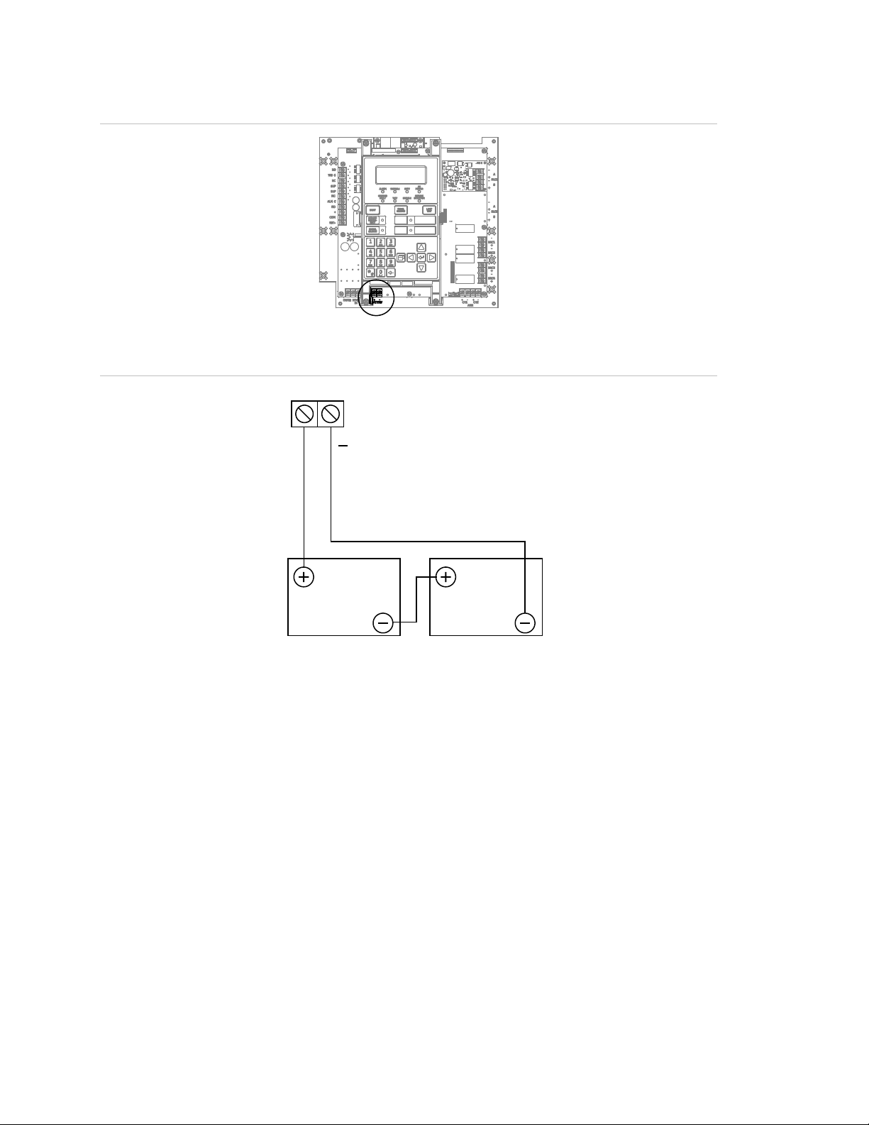
Caution: Connect and disconnect standby batteries only with the AC power
applied.
The control panel has a 24 VDC rechargeable battery circuit that is capable of
charging up to two 26 Ah sealed lead acid batteries.
The table below lists the batteries that can be installed in the control panel
cabinets. Up to two 11 Ah batteries will fit in the eFSA64 control panel cabinet
and two 18 Ah batteries will fit in the eFSA250 point control panel cabinet. If
larger batteries are required, you must use an approved battery cabinet. To
determine which battery the system requires, use the “Battery calculation
worksheet” on page 212.
Table 3: Batteries for eFSA64 and eFSA250 panels
Manufacturer Rating
GS Battery, Inc. 12 volts, 4.5 Ah
GS Battery, Inc. 12 volts, 7.2 Ah
GS Battery, Inc. 12 volts, 11 Ah
GS Battery, Inc. 12 volts, 18 Ah
GS Battery, Inc. 12 volts, 26 Ah
E-FSA64 and E-FSA250 Technical Reference Manual 7
Page 20
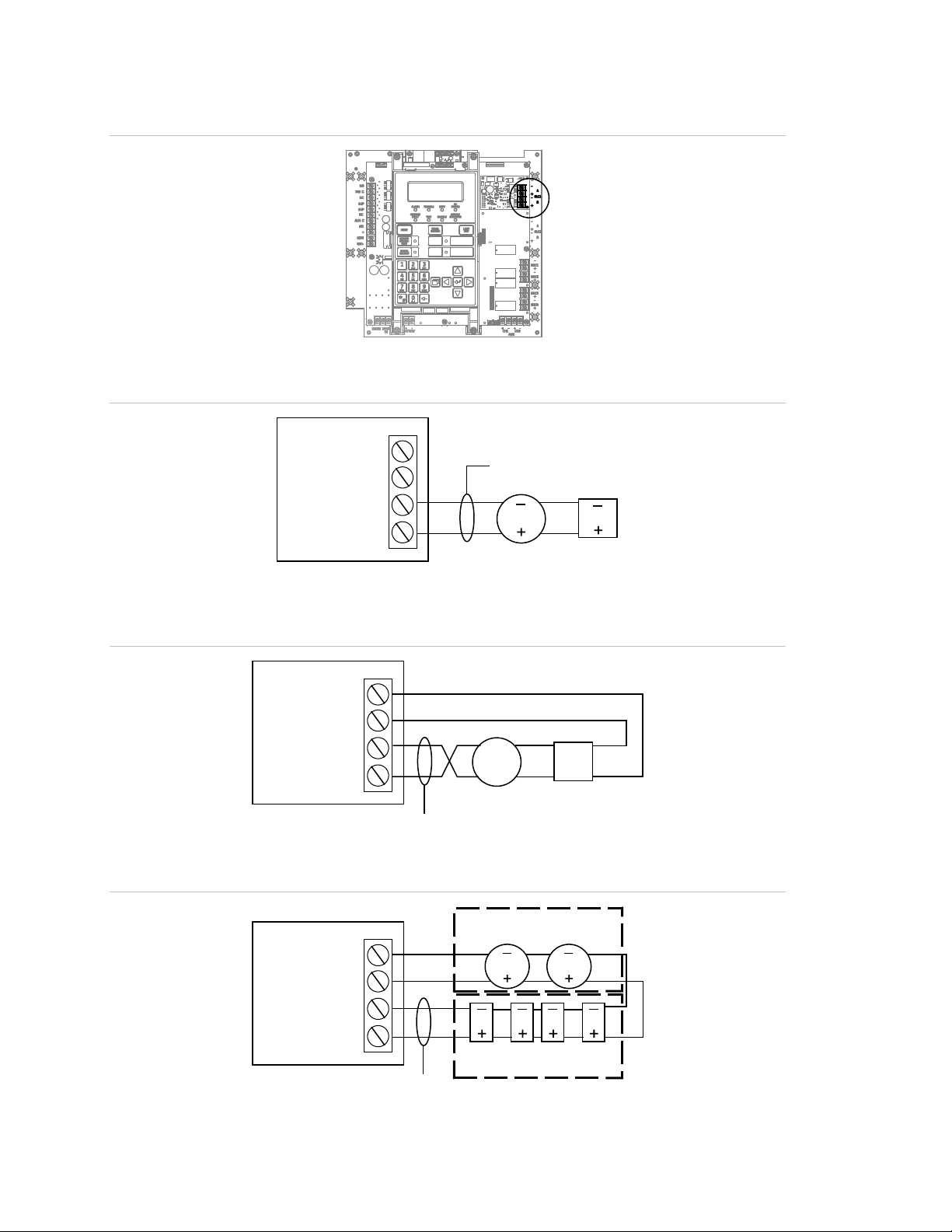
Chapter 1: Installation and wiring
TB8
Red
Figure 8: Battery wiring location
Figure 9: Battery wiring
+
Black
12 VDC
Battery
12 VDC
Battery
Notification appliance circuit wiring (TB2)
The control panel provides either two or four notification appliance circuits
depending on which model you have. Each circuit can be individually configured
for continuous, temporal, synchronized, coded, or city tie output.
Circuit specifications
• Class B or Class A.
• Circuit voltage: 24 VFWR, regulated
• Circuit current
Edwards Signaling eFSA64 panel:
3.75 A total, 2.5 A max. per circuit at 120/230 VAC 60 Hz input voltage
3.0 A total, 2.5 A max. per circuit at 230 VAC 50 Hz input voltage
8 E-FSA64 and E-FSA250 Technical Reference Manual
Page 21
Chapter 1: Installation and wiring
Edwards Signaling eFSA250 panel:
6.0 A total, 2.5 A max. per circuit at 120/230 VAC 60 Hz input voltage
5.0 A total, 2.5 A max. per circuit at 230 VAC 50 Hz input voltage
• Max. resistance: 26 Ω total
• Max. capacitance: 0.35 µF
• EOLR: 15 kΩ, 1/2 W (P/N EOL-15)
• Synchronization: For NACs wired Class A or Class B, signal synchronization
is supported system-wide (all NAC circuits).
• Ground fault impedance: 0 to 5 kΩ
• Power-limited and supervised
Notes
• On the Edwards Signaling eFSA64 panel, Class A wiring is available only
when the optional SA-CLA expansion card is installed. Refer to the SA-CLA
Class A Interface Card Installation Sheet (P/N 3101094) and to the topic “SA-
CLA wiring” on page 23.
• Listed EOLRs must be installed as shown for proper supervision.
• Marking indicates the output signal polarity when the circuit is active. Polarity
reverses when the circuit is not active. Wire notification appliances
accordingly. Notification appliance polarity is shown in the active state.
• Installation limits are subject to acceptance by the AHJ.
Figure 10: NAC wiring location
E-FSA64 and E-FSA250 Technical Reference Manual 9
Page 22
Chapter 1: Installation and wiring
+
–
NAC1–
NAC2+
NAC2–
NAC1+
EOLR
TB2
+
–
+
–
+
–
TB2
TB6
EOLR
NAC3–
NAC4+
NAC4–
NAC3+
EOLR
NAC1–
NAC2+
NAC2–
NAC1+
+
–
+
–
+
–
+
–
+
–
+
–
+
–
+
–
TB2
TB6
NAC1–
NAC2+
NAC2–
NAC1+
+
+
–
–
+
–
+
–
+
–
+
–
Figure 11: eFSA64 panel Class B NAC wiring
Figure 12: eFSA250 panel Class B NAC wiring
Figure 13: eFSA250 panel Class A NAC wiring
Note: For eFSA64 Class A NAC wiring, see “SA-CLA wiring” on page 23.
10 E-FSA64 and E-FSA250 Technical Reference Manual
Page 23

Chapter 1: Installation and wiring
Addressable device loop wiring
The eFSA64 and eFSA250 control panels each have one addressable device
circuit that you can use with addressable detectors and modules. The eFSA64
supports up to 64 devices. The eFSA250 supports up to 127 addressable
devices on the initial loop and an additional 127 devices on the optional second
loop. The loop circuit is supervised for open circuits, short circuits, and ground
faults.
Note: For a complete list of devices that can be connected to this circuit, refer to
the eFSA64 and eFSA250 Series Compatibility List (P/N 3101199).
Caution: The E-2WIRE module cannot be used on a device loop with isolator
modules or isolator bases.
Circuit specifications
• Class B or Class A
• Communication line voltage: Maximum 20.6 V peak-to-peak
• Circuit current: 0.5 A max.
• Total resistance: 66 Ω max.
• Total capacitance: 0.7 µF max.
• Resistance between isolators: Limited only by overall wire run lengths
• Isolators: 64 maximum (total both isolator bases and modules)
• Ground fault impedance: 0 to 5 kΩ
• Power-limited and supervised
• Synchronization: Signal synchronization is supported on a system-wide basis
(all device loops) when using an E-NAC addressable notification appliance
circuit (NAC) module and Genesis or Enhanced Integrity notification
appliances
Installation limits are subject to acceptance by the AHJ.
E-FSA64 and E-FSA250 Technical Reference Manual 11
Page 24
Chapter 1: Installation and wiring
Loop card
device
SLC
Loop SEC
+
–
Loop PRI
+
–
Loop card
Loop
devices
Isolator
module
Isolator
module
UL/ULC listed enclosure
Data line
Loop devices
with isolator base
Figure 14: Device loop wiring location
Figure 15: Class B wiring (Style 4)
–
A
+
–
B
+
Data line
Loop
device
Loop
Figure 16: Class A wiring (Style 6)
Loop 1 SEC
–
+
Loop 1 PRI
–
+
Loop card
+
–
Loop
device
+
–
Loop
device
Figure 17: Class A wiring (Style 7)
12 E-FSA64 and E-FSA250 Technical Reference Manual
Page 25
Chapter 1: Installation and wiring
Secondary
Comm
Loop card LEDs
There are three LEDs on the card that indicate loop communication status.
Primary is the primary communication circuit. Secondary is the Class A return
communication when wiring is Class A.
Figure 18: Loop card LEDs
Primary
Note: “Comm” refers to overall communication
Alarm, trouble, and supervisory relay wiring
(TB3)
The control panel provides alarm, trouble, and supervisory relays.
• The trouble relay changes over on any trouble event (common trouble)
• The supervisory relay changes over on any supervisory event (common
supervisory)
• The alarm relay changes over on any alarm event (common alarm)
Note: Relay circuits can only be connected to power-limited sources. Relays are
not supervised.
Relay specifications
• Alarm and trouble: Form C, 24 VDC at 1 A resistive
• Supervisory: Form A, 24 VDC at 1 A resistive
E-FSA64 and E-FSA250 Technical Reference Manual 13
Page 26
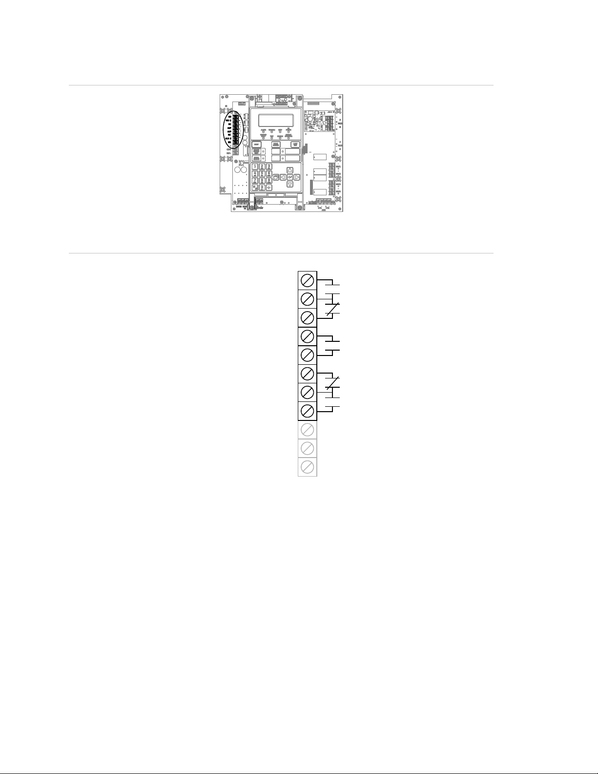
Chapter 1: Installation and wiring
TB3
Common supervisory
NO
NC
NC
NO
NO
Note: The figure above shows the panel in a normal state.
Figure 19: Terminal wiring location
Figure 20: Relay wiring terminals
Common trouble
relay
relay
Common alarm
relay
Auxiliary/Smoke
power output
14 E-FSA64 and E-FSA250 Technical Reference Manual
Page 27
Chapter 1: Installation and wiring
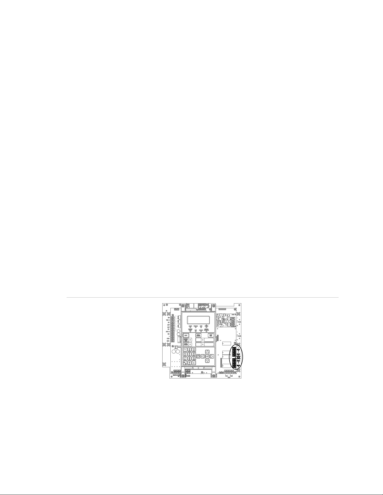
Remote annunciator wiring (TB4)
The control panel provides a connection for up to eight remote annunciators.
Circuit specifications
• Class B or Class A
Note: The Edwards Signaling eFSA64 panel requires the SA-CLA card to
support Class A and redundant Class B circuits. Refer to “SA-CLA wiring” on
page 23, or to installation sheet P/N 3101094.
• Circuit voltage: 2.55 V peak-to-peak average
• Circuit current: 30 mA max.
• Circuit resistance: 90 Ω
• Circuit capacitance: 0.3 µF
• Ground fault impedance: 0 to 5 kΩ
• RS-485 communications speed: 9600 baud
• Wiring: 18 to 14 AWG (1.0 to 2.5 mm2) twisted pair
• Wire run: 4,000 feet (1,219 m) max.
• Power-limited and supervised
Notes
• Refer to the R-Series Remote Annunciators and Expander Installation and
Operation Guide (P/N 3100969) or the R-Series annunciator installation
sheets for detailed wiring information
• Installation limits are determined by the AHJ
Figure 21: Remote annunciator wiring location
E-FSA64 and E-FSA250 Technical Reference Manual 15
Page 28
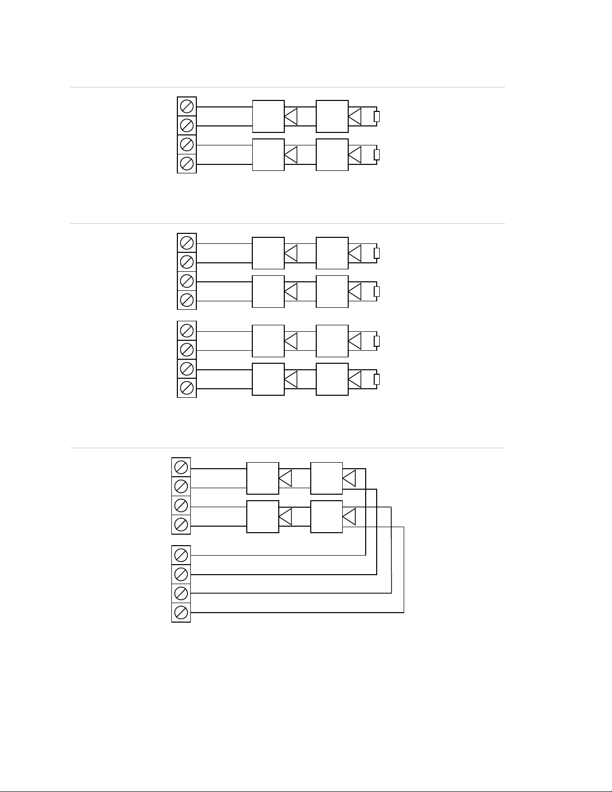
Chapter 1: Installation and wiring
+
–
TB4
+
–
Channel 1 Channel 2
CH1 (+) IN
CH1 ( ) IN
–
CH2 (+) IN
CH2 ( ) IN
–
Annunciator
Channel 1 Channel 2
Figure 22: Annunciator channel wiring (Class A)
Note: To use the Class A option, you must install the SA-CLA module in the eFSA64.
Figure 23: Annunciator channel wiring (Class B)
+
+
–
–
TB4
Annunciator
CH1 (+) IN
CH1 ( ) IN
–
CH2 (+) IN
CH2 ( ) IN
–
Auxiliary/smoke power output wiring
The control panel provides resettable and continuous AUX power output circuits.
Use the resettable AUX power output for devices such as four-wire detectors or
beam detectors. Use the continuous AUX power output for devices such as
remote annunciators or door holders.
Notes
• If you do not need resettable AUX power, you can configure the resettable
AUX power output to supply continuous power.
• For a complete list of devices that can be connected to this circuit, refer to the
eFSA64 and eFSA250 Series Compatibility List (P/N 3101199).
16 E-FSA64 and E-FSA250 Technical Reference Manual
Page 29
Chapter 1: Installation and wiring
Circuit specifications
• Circuit voltage range: 21.9 to 28.3 V
• AUX 1 + AUX 2 can supply 1.5 A total. If more than 1.5 A is required, you
must use a power-limited and regulated 24 VDC auxiliary/booster power
supply that is UL/ULC and FM Listed (if the installation requires FM
regulation) for fire protective signaling systems.
• For a complete list of auxiliary/booster power supplies, refer to the VS1 and
VS2 Series Compatibility List (P/N 3101065). Also refer to the Technical
Reference Manual (P/N 387515) for a list of compatible power supplies, if
you need to power GSA-REL module.• Continuous circuit (AUX power 1): 24
VDC nominal at 500 mA. Use this circuit to supply 24 VDC continuous power.
• Resettable circuit (AUX power 2): 24 VDC nominal at 500 mA (1 A possible if
you reduce total available NAC power by 500 mA). Use this circuit to provide
24 VDC resettable power. You can configure AUX power 2 as a continuous
circuit if you do not need a resettable circuit.
• Special application circuits
• Ground fault impedance: 0 to 5 kΩ
• Supervised and power-limited
Figure 24: Auxiliary/smoke power wiring location
E-FSA64 and E-FSA250 Technical Reference Manual 17
Page 30

Chapter 1: Installation and wiring
–
+ Continuous (AUX 1)
Auxiliary/Smoke
power output
TB3
+ Resettable (AUX 2)
Common trouble
relay
Common supervisory
relay
Common alarm
relay
Figure 25: Auxiliary/smoke power output terminals
18 E-FSA64 and E-FSA250 Technical Reference Manual
Page 31

Chapter 1: Installation and wiring
Receiver
Ademc
FBII
Osborne
Radionics
Silent Knight
Sur
Note: I
card firmware is V2.2 or earlier, the Timeout Seconds must be set to 60, the Hello Timer set to
75, and the Line Cut timer in the line car
firmware version in the receiver or there are communication faults between the panel and the
receiver, then these settings are recommended.
SA-DACT wiring
The optional SA-DACT provides communications between the control panel and
the central station over a telephone line system. The SA-DACT is listed for use
with the following DACRs.
Table 4: DACRs used with the SA-DACT
Models Formats
o 685 Contact ID
CP220 Contact ID
-Hoffman OH2000 and OH2000E with an OH2000E-LC
line card installed (see note below)
D6600 Contact ID
9500, 9800 Contact ID
-Gard MLR1, MLR2, MCDI TLR, TLR+, SG-SLR,
MLR2000
f the line card firmware is V2.2 or later, use the default CMS network settings. If the line
d itself set to 175 seconds. If you are unsure of the
Contact ID
Contact ID
Phone lines connect to the dialer using connectors on the dialer’s main circuit
board. Phone line 1 connects to connector J1 and phone line 2 connects to
connector J4.
The SA-DACT comes with two, eight position, four conductor modular cords.
Connect one end of each cord to connector J1 and J2. Connect the other end of
each modular cord to either an RJ-31X or RJ-38X. Wire the RJ-31X block as
shown below.
Note: Install a listed secondary telephone protector between the telco network
and the SA-DACT card. The SA-DACT card must be the next piece of equipment
that connects to the telephone company (TELCO) telephone lines.
Circuit specifications
• Operating current (standby or alarm): 41 mA nominal, 100 mA max.
• Phone line type: One or two loop-start lines on a public, switched network
• Phone line connector: RJ-31/38X (C31/38X)
E-FSA64 and E-FSA250 Technical Reference Manual 19
Page 32

Chapter 1: Installation and wiring
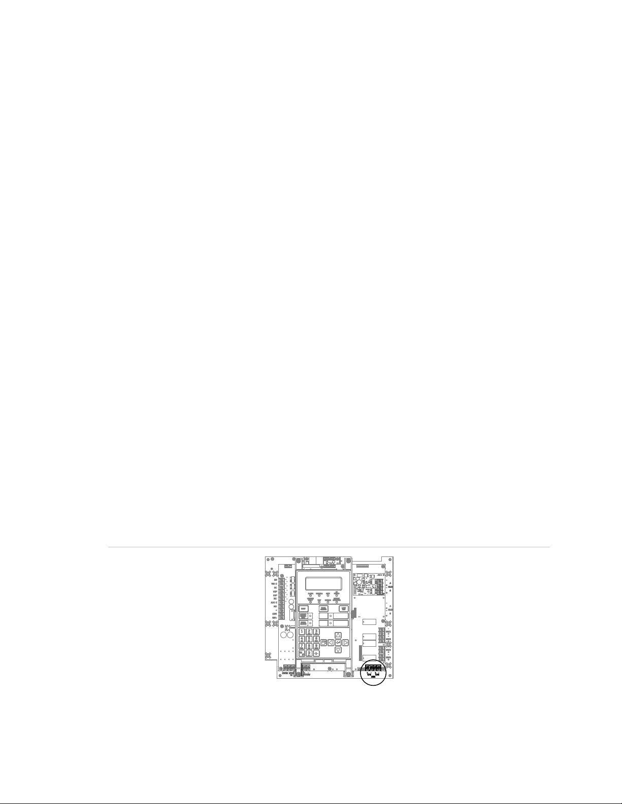
Protected premises
PBX
Figure 26: SA-DACT wiring location
Figure 27: SA-DACT wiring
TELCO
Line 2
Tip
Ring
punch down block
Tip
Ring
Telephone protector Telephone protector
4 5
3
2
1
TELCO
Line 1
6
7
8
RJ-31X block
(supplied by installer)
LINE 2
Tip
Ring
1
4 5
3
6
7
2
LINE 1
8
8-position, 4-conductor
modular cords
(supplied by installer)
Tip
Ring
J4
J1
20 E-FSA64 and E-FSA250 Technical Reference Manual
Page 33

Chapter 1: Installation and wiring
SA-232 wiring
The optional RS-232 card can be wired to a printer to print system events or
wired to a computer to read from and write to the panel using the configuration
utility.
Circuit specifications
• Serial communications
Asynchronous communications maximum resistance: 13 Ω
Maximum capacitance: 0.7 µF
• Wire length: 50 feet max.
• Signal voltage: ± 10 V
• Operating current (standby or alarm): 13 mA nominal, 20 mA max.
• Printer communication speed: 9600 baud
• Power-limited and unsupervised. Supervised when the Supervised Printer
panel programming option is enabled.
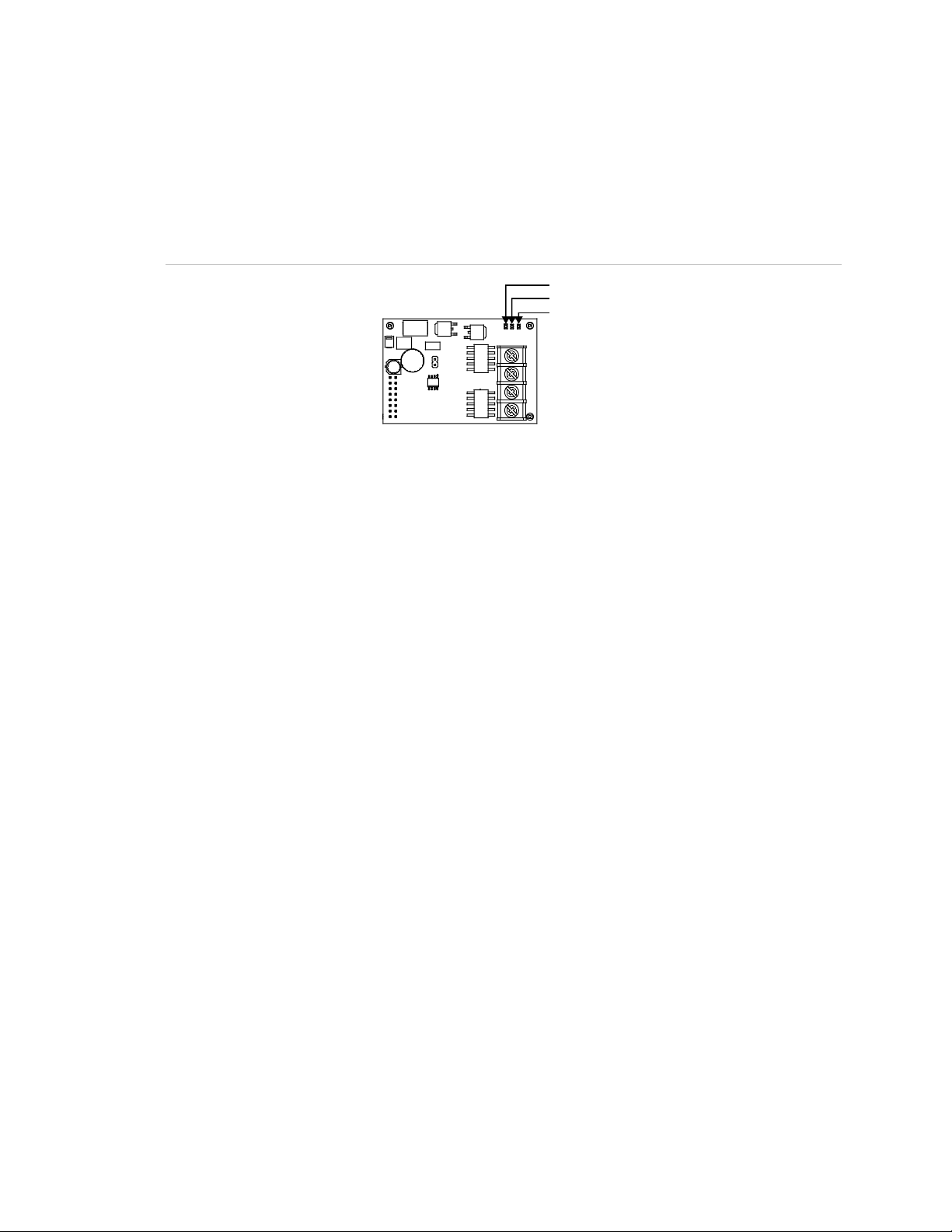
Figure 28: SA-232 wiring terminals
GNDRTS
TXD RXD
Printer wiring
Note: The printer must be configured through programming for proper operation.
To install wiring to a printer:
1. Locate the serial port on the back of the printer.
2. Connect the DB-25 end of the RS-232 cable to the serial port on the back of
the printer.
3. Connect the other end of the RS-232 cable to the RS-232 card.
E-FSA64 and E-FSA250 Technical Reference Manual 21
Page 34

Chapter 1: Installation and wiring
RS-232 cable
DB-25 male
Printer
To RS-232 card
DB-25 serial port
on back of printer
LINE
FEED
FORM
FEED
TOP
SET
SELECT ALARM POWER PI TCH MO DE
PIN 25
PIN 1
DB-25 male
(front view)
Pin 7: COM (black wire)
Pin 20: DTR (green wire)
SA
GND
R
TXD
RXD
Figure 29: Printer wiring
Figure 30: DB-25 pin connections
Table 5: SA-232 card to printer DB-25 connections
-232 card DB-25 Description
COM (pin 7) Black wire (ground connection)
TS DTR (pin 20) Green wire (printer supervision)
RXD (pin 3) White wire (communication)
TXD (pin 2) Red wire (communication)
Computer download wiring
To install wiring to a computer:
1. If you have a connected printer, disconnect it.
2. Locate a serial port (COM port) on the back of the computer.
3. Connect the DB-9 end of the RS-232 cable to the COM port on the back of
the computer.
4. Connect the other end of the RS-232 cable to the RS-232 card.
22 E-FSA64 and E-FSA250 Technical Reference Manual
Page 35

Chapter 1: Installation and wiring
Computer
DB-9 COM port
Pin 2 RXD
Pin 5 COM
SA
GND
RTS
TXD
RXD
[1] Wire colors refer to Model 260097 RS-232 Cable
Figure 31: Computer download wiring
on back of computer
DB-9 female
RS-232 cable
To RS-232 card
Figure 32: Pin designations on female DB-9 plug (back view)
Pin 3 TXD
Table 6: SA-232 card to computer DB-9 connections
-232 card DB-9 Description [1]
COM (pin 5) Black wire (ground connection)
- Not used
RXD (pin 2) White wire (communication)
TXD (pin 3) Red wire (communication)
SA-CLA wiring
The SA-CLA card is used to supply wiring for Class A NACs and redundant
Class B remote annunciator circuits on eFSA64 control panels.
Circuit specifications
• Operating current
Standby: 3 mA
Alarm: 60 mA max.
• Max. resistance: 26 Ω
• Max. capacitance: 0.35 µF
• Max. current: 2.5 A per circuit
E-FSA64 and E-FSA250 Technical Reference Manual 23
Page 36

Chapter 1: Installation and wiring
• Ground fault impedance: 0 to 5 kΩ
• Power-limited and supervised
Figure 33: SA-CLA Class A NAC wiring
Figure 34: SA-CLA Redundant Class B remote annunciator circuit
SA-ETH wiring
The optional SA-ETH card provides a standard Ethernet network connection for
connecting to a local network or connecting to a computer to read from or write to
the panel using the configuration utility.
24 E-FSA64 and E-FSA250 Technical Reference Manual
Page 37

Chapter 1: Installation and wiring
Network cable
To network
(PC, router, switch, etc.)
Ethernet card
LED 4 (DS4): Collision
Circuit specifications
• Ethernet: 10/100BaseT
• Network cable: Cat 5/6 crossover cable or straight through cable
• Operating current (standby or alarm): 34 mA nominal, 41 mA max.
• Wire runs: 200 feet (60 m) max., Cat 5 cable (panel to communication
equipment)
Figure 35: SA-ETH wiring
connection
Ethernet card
Figure 36: SA-ETH LEDs
LED 1 (DS1): Link
LED 2 (DS2): Speed
LED 3 (DS3): Duplex
CTM module wiring
The CTM (City Tie Module) is an interface between the control panel notification
appliance circuit and a master box. It provides off-premises signal transmission
for systems that must comply with NFPA requirements for Auxiliary Protective
Systems. The CTM activates a local energy fire alarm box. For detailed
information and wiring, refer to the CTM Installation Sheet (P/N 3101025).
E-FSA64 and E-FSA250 Technical Reference Manual 25
Page 38

Chapter 1: Installation and wiring
appliance circuit
Normal condition
reporting system
appliance circuit
reporting system
Alarm condition
[3] Supervised and power-limited
Requirements
When connecting a CTM to the panel, the following hardware and programming
requirements must be met:
• The CTM must be connected to either a panel NAC, or a NAC module
• The NAC used must be dedicated to CTM use only
• All alarm points or zones (if programmed as a zoned system) must be
programmed to activate the dedicated NAC
• The NAC used must be programmed as City Tie
Wiring
The following wiring diagrams show how the polarity switches during an alarm
condition.
Figure 37: CTM module wiring (panel in normal condition)
_
+
[4]
+
_
[3]
Notification
CTM
2
1
[5]
_
1
2
+
3
4
Figure 38: CTM module wiring (panel in alarm condition)
CTM
+
1
_
_
+
_
+
[3]
[4]
Notification
[1] 200 mA into a 14.5 Ω trip coil max. loop
resistance = 25 Ω
[2] This circuit is nonpower-limited and is
supervised for grounds and opens, but
not shorts
2
1
2
3
4
[5]
[4] NAC must be programmed for city tie
[5] CTM must be mounted in the same room
as the panel
[6] 15 kΩ end-of-line resistor
[6]
[6]
[1] [2]
[1]
[2]
Master box
_
+
Public fire alarm
Master box
+
_
Public fire alarm
26 E-FSA64 and E-FSA250 Technical Reference Manual
Page 39

Chapter 1: Installation and wiring
24VOUT
Control panel
From ALRM on RPM (brown wire)
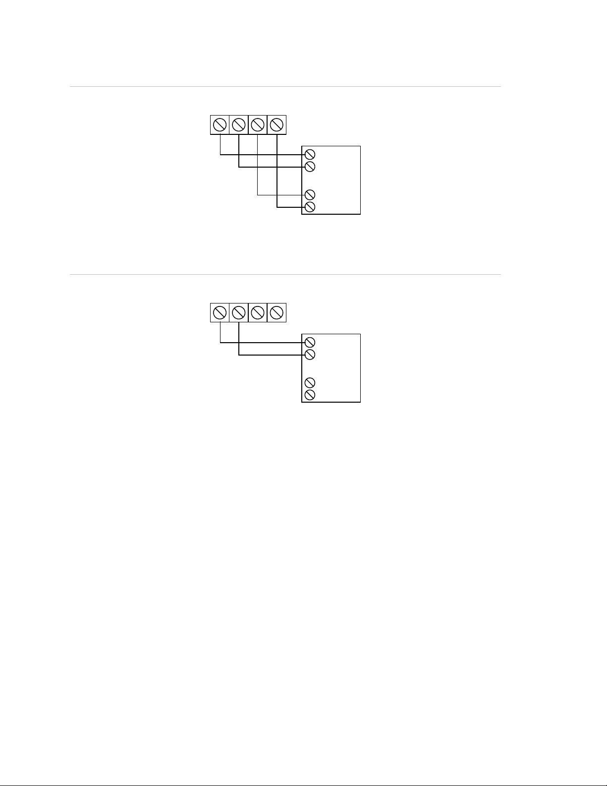
RPM module wiring
The Reverse Polarity Module (RPM) is an interface between the control panel
and a reverse polarity receiver. It provides off-premises signal transmission for
systems that must comply with NFPA requirements. When used as a reverse
polarity remote station transmitter, it can be connected to either a single circuit
(alarm or alarm and trouble) or up to three circuits (alarm, supervisory, and
trouble). Below are application diagrams for using the RPM module. For detailed
information and wiring, refer to the RPM Installation Sheet (P/N 3100430).
Notes
• The RPM must be mounted in conduit, in an MFC-A enclosure, immediately
adjacent to the panel.
• All relays are unsupervised and must be connected to a power-limited source.
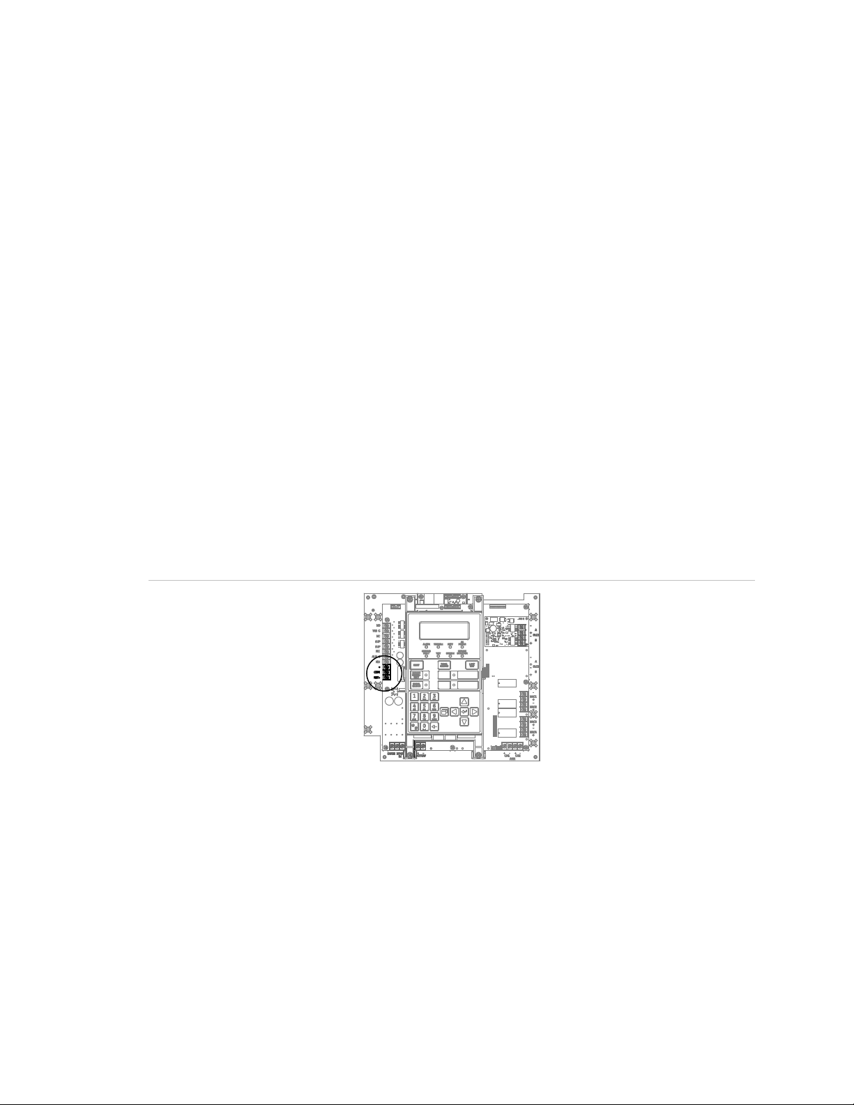
Figure 39: Terminal wiring location
Figure 40: Alarm transmitted only
TB3
NO
C
TRBL
NC
SUP
NC
ALM
C
NO
+
From COM on RPM (black wire)
+
E-FSA64 and E-FSA250 Technical Reference Manual 27
From +24 on RPM (red wire)
Page 40

Chapter 1: Installation and wiring
From ALRM on RPM (brown wire)
From TRBL on RPM (yellow wire)
Control panel
24VOUT
From SUPV on RPM (orange wire)
Control panel
24VOUT
Figure 41: Alarm and trouble transmitted on a single circuit
TB3
NO
C
TRBL
NC
SUP
NC
ALM
C
NO
+
From COM on RPM (black wire)
+
Note: JP1 on the RPM must be OUT.
From +24 on RPM (red wire)
Figure 42: Alarm, supervisory, and trouble transmitted on separate circuits
Note: JP1 on the RPM must be IN.
TB3
NO
ALM
C
NC
SUP
NC
C
NO
TRBL
+
+
From TRBL on RPM (yellow wire)
From ALRM on RPM (brown wire)
From COM on RPM (black wire)
From +24 on RPM (red wire)
28 E-FSA64 and E-FSA250 Technical Reference Manual
Page 41

Chapter 2
Front panel programming
Summary
This chapter shows how to configure the system using the control buttons on the
front panel. For information on programming the system using the optional
Configuration Utility (CU), refer to the Help available in the CU.
Content
UL 864 programming requirements 31
Getting started 32
What is a zone? 32
What is a correlation group? 32
What is in-suite signal silence? 34
Programming modes 35
Using the programming control buttons 36
Factory default settings 36
Device type descriptions 43
Displaying the Program menu 48
Setting the time and date 48
Setting daylight saving time 49
Sample values for daylight saving time 50
Changing the passwords 51
Restoring the factory default settings 51
Setting up the programmable keys 52
Clearing the event history log 56
Updating the firmware 57
Download status 58
Restarting the panel 60
Enabling RS232 communication 60
Auto programming the panel 61
Auto programming options 62
E-FSA64 and E-FSA250 Technical Reference Manual 29
Page 42

Chapter 2: Front panel programming
Dialer options 64
NET options 66
Auto programming procedure 66
Labeling devices 68
Labeling zones 68
Performing incremental programming 69
Incremental programming options 69
Incremental programming procedure 70
Labeling devices 71
Labeling zones 72
Adding and removing devices from programmed systems 73
Device programming options 73
Adding devices 82
Removing devices 83
Advanced programming 84
Overview 84
Changing loop configuration options 85
Correlation group programming 86
Adding and removing panel events 90
Programming in-suite signal silence 92
Programming fast groups for sounder bases 93
Device programming 95
Programming relay and sounder detector bases 103
Programming relay modules and bases as latched output devices 104
Loop 2 enable 107
Zone programming 107
Panel programming 109
Central monitoring station device programming 115
Panel operation programming 125
Event programming 128
30 E-FSA64 and E-FSA250 Technical Reference Manual
Page 43

Chapter 2: Front panel programming
UL 864 programming requirements
NOTICE TO USERS, INSTALLERS, AUTHORITIES HAVING JURISDICTION, AND OTHER
INVOLVED PARTIES
This product incorporates field-programmable software. In order for the product to comply with
the requirements in the Standard for Control Units and Accessories for Fire Alarm Systems, UL
864, certain programming features or options must be limited to specific values or not used at
all as indicated below.
Programmable
feature or option
AC fail delay Y 0 to 15 hours 1 to 3 hours 3 hours
Telephone line cut
supervision
duration
Telephone line
ground fault
Transmission test
frequency
Dialer mode Y Dual line
Dialer retries Y 5 to 10 5 minimum 5 retries
Dialer retry time Y 1 to 45 seconds Yes 5 seconds
Send event restore
codes
Permitted in
UL 864 (Y/N)
Y 1 to 120 seconds
Y Disabled
Y 0 to 45 days 1 (daily) 1 (daily)
Y No
Possible
settings
Enabled
Single line
Modem only
None
Yes
Settings
permitted in UL
864
10 to 120
seconds
Enabled Enabled
Dual line
Single line [2]
Modem only [3]
None [3]
Yes Yes
Panel default
120 seconds
Dual line
Swinger shutdown N Off
1 to 255
Zone resound Y On
Off
[1] Allowed only if the IDC is connected to the latching alarm device
[2] Allowed only when the supervising station supervises the telephone line and annunciates
fault conditions within 200 seconds
[3] Prohibited when the control panel is connected to a supervising station
E-FSA64 and E-FSA250 Technical Reference Manual 31
Off Off
On On
Page 44

Chapter 2: Front panel programming
Getting started
You can program the system using the command buttons on the front panel, or a
PC with the optional configuration utility (CU), or both. If you plan to use the
configuration utility, refer to the Help system for complete programming
instructions.
What is a zone?
A zone is a collection of points that are grouped together in the project database
in the same manner that the system designer divided the protected premises.
Zones provide a single zonal response and are used to limit the number of event
messages processed by the system. Firewall designations, planned evacuation
criteria, architectural design, and other factors determine how points are grouped
into zones.
What is a correlation group?
A correlation group is a collection of inputs that activate a collection of outputs.
During loop configuration, input devices, zones, and events are correlated with
NACs and other output devices.
Output activations depend on the activation count and delay options. The
activation count controls the number of input activations that are required to
activate the group’s outputs. The delay controls the number of seconds the
system waits before activating the group’s outputs. For example:
• When the correlation group’s activation count is 1 (default), the activation of
any input device in the group turns on every output device in the group.
• When the activation count is 3, every output device in the group is activated
when at least three input devices activate.
• When the correlation group’s activation count is 3 and three or more input
devices turn on, the system waits the delay time before activating the group’s
outputs.
32 E-FSA64 and E-FSA250 Technical Reference Manual
Page 45

Chapter 2: Front panel programming
Correlation group
Correlation
group 001
Correlation
group 002
Correlation
group 003
Correlation
group 199
Zone, NAC, or
output device
Zone, NAC, or
output device
Zone, NAC, or
output device
Zone, NAC, or
output device
Figure 43: Correlation group operation
(links input devices to output devices)
Input devices (smoke
detector, pull station) by
themselves or in a zone
Input
device
Zone
input
device
Activation of an input device in the correlation group
turns on every output device in the correlation group
Output devices and
NAC devices (strobe,
horn)
Output
device
NAC
output
device
A correlation group can contain any combination of input devices, output devices,
NACs, events, and zones. Input devices, output devices, NACs, events, and
zones can be assigned to more than one correlation group. There are 199
available correlation groups. You can add a forty-character, alphanumeric
description to each correlation group.
Figure 44: Inputs and outputs to correlation groups
During auto programming the following devices are assigned to correlation group
001:
• All addressable smoke detectors
• All addressable pull stations
• All E-2WIRE modules
• All E-IDC1B (mini modules)
• Any circuit on an E-IDC2B or E-IDC1A configured with the P1 or P2 switch in
position 1 (alarm)
E-FSA64 and E-FSA250 Technical Reference Manual 33
Page 46

Chapter 2: Front panel programming
• Circuit one on all E-IDCWS modules
• All E-NAC and E-RLY modules
• All panel NACs
• All zones configured as alarm
The following inputs are not included in correlation group 001 during auto
programming:
• Relay and sounder bases with the Follow option set to Head. All sounder
bases are programmed as Relay during auto programing.
Note the following:
• Any items included in correlation group 001 can be removed manually using
front panel programming or the configuration utility.
• Any detectors, modules, or zones, where the type is changed to a type other
than alarm, should be removed manually from correlation group 001 to avoid
activating that correlation group.
• If zoning is used, the zones must be in the appropriate correlation group so
devices assigned to that zone activate the correlation group.
What is in-suite signal silence?
In-suite signal silence is a form of automatic alarm silencing that can be enabled
for correlation groups. The function is used in residential complexes to minimize
the annoyance of false alarms within living quarters. When an alarm input device
activates, evacuation signals activate normally. After one minute, alarms in living
quarters outside the alarm zone deactivate briefly. This interval is called the
shutdown period and gives building personnel time to investigate the problem.
Room evacuation signals in the alarm zone and hallway signals throughout the
building remain active.
If the alarm has not been cleared within programmed allotted time (1 to 10
minutes), or if a subsequent alarm occurs, all signals resound. The shutdown
period can be adjusted at the panel. In-suite signal silence can be turned off
completely at the panel by setting the Suite Signal Silence option to Off (default).
This setting is found at Program > Advanced Program > Panel Operation.
Notes
• Only alarm events can initiate in-suite signal silence.
• Only the first alarm is silenced by in-suite signal silence. Any additional
alarms sound as programmed and are not automatically silenced.
34 E-FSA64 and E-FSA250 Technical Reference Manual
Page 47

Chapter 2: Front panel programming
• In-suite signal silence applies only to output devices and NACs that are
configured as silenceable. It cannot be used in local alarm signaling
applications.
• You cannot use a delay timer with in-suite correlation groups.
• No special hardware is required.
• In-suite signal silence is required by Ontario Building Code 3.2.4. For
instructions on programming in-suite signal silence in a typical system, see
“Adding and removing panel events” on page 90
Programming modes
You can choose from three levels of program automation: Auto programming,
incremental programming, or advanced programming. These are discussed in
the following sections.
Auto programming
The Auto Program command is used to automatically configure the control panel
and remote annunciators from their respective front panels.
Auto programming replaces the existing project database with a default project
database based on the hardware configuration that it detects. The default project
database configures the system as a general fire alarm system that activates all
notification appliance circuits when any fire alarm input is activated.
Auto programming can also be used as a first step, to be followed by some
advanced programming to customize individual settings. The Auto Program
command lets you choose:
• Automatic zone assignments
• The event notification level to use
• Manual or automatic device and zone labeling during auto programming
• The “base follow” option for relay and sounder bases
• CMS network and dialer options
Note: Auto programming does not overwrite the previous CMS programming.
However, the restore panel defaults option in the program menu does change the
CMS configuration.
To auto program a panel, see “Auto programming the panel” on page 61
Incremental programming
The Incremental Program command is used to make changes to a panel that has
already been programmed. Incremental programming lets you add and label
devices and zones in the existing database without affecting any other settings.
E-FSA64 and E-FSA250 Technical Reference Manual 35
Page 48

Chapter 2: Front panel programming
Button
Arrow buttons
Menu button
Enter button
Alphanumeric
keypad
Cancel button
Incremental programming is typically used to add or remove an additional loop of
devices or a large number of devices to the system. See “Performing incremental
programming” on page 69.
The Unconfigured Alarm command is used to add an additional device or several
devices to a system without using the Incremental Program command. When a
new device is added or a device is removed, the panel signals a “trouble active”
event and indicates on the LCD that there is an unconfigured device. The device
can then be programmed and added to the database. This method is typically
used to add just a few devices. See “Adding and removing devices from
programmed systems” on page 73.
Advanced programming
Advanced programming is used to apply custom programming to a new or
previously programmed fire alarm system. Advanced programming lets you
configure each option individually. See “Advanced programming” on page 84.
Using the programming control buttons
The following buttons are used with the LCD to program the panel.
Table 7: Programming control buttons
Description
Right arrow: Displays a submenu, or toggles between multiple settings such
as “Yes” and “No.”
Left arrow: Scrolls through a programming option’s selections
Up arrow: Moves the cursor up
Down arrow: Moves the cursor down
Opens and closes the main menu
Executes a command, displays a submenu, displays the Save function, or
scrolls through a programming option’s selections.
Used to enter numbers and letters needed for the various settings. Pressing
and holding a key scrolls through alternate values. For example, pressing
and holding the “2” key scrolls between 2, A, B, and C.
Returns to the previous menu level. Exits menu mode if you are at the
highest menu level. Deletes text when editing labels, etc.
Factory default settings
The panel is shipped from the factory with default settings. You can accept or
change these settings as needed.
36 E-FSA64 and E-FSA250 Technical Reference Manual
Page 49

Chapter 2: Front panel programming
•
•
•
•
•
•
•
•
•
•
•
•
•
•
•
Note: Depending on panel equipment and programming, some of these settings
may not be available.
Default passwords
The panel comes standard with a set of default passwords. These are:
• Level 1: 1111
• Level 2: 2222
• Remote annunciator: 3333
Note: We recommend that you change the default passwords after programming
the system.
Default panel operation settings
Language: English
• Night start: 18:00
Marketplace: US
AC fail delay: 3 hours
Zone resound: On
Reset inhibit: Off
Auto signal silence: Off
Suite signal silence: 10 minutes
Day start: 06:00
Other default panel settings
Daylight saving
Enabled: No
Month start: 03
Month end: 11
Week start: 1
Week end: 0
RS232 CU Enable: Off
Lock remote read: No
Default panel configuration settings
IP: 192.168.001.003
• Date format U.S.: MM/DD/YYYY
• Aux power reset: On
• LCD banner: Blank
• Event notification: Device
• Key #1: NONE
• Key #2: NONE
Weekday start: 0
Weekday end: 0
Hour start: 02
Hour end: 02
Offset minutes: 60
Subnet mask: 255.255.255.0
Gateway: 000.000.000.000
Panel NACs
Class: Class B
Type: Continuous silenceable
Correlation group: 1
E-FSA64 and E-FSA250 Technical Reference Manual 37
Page 50

Chapter 2: Front panel programming
•
Disable > NET: Yes
Disable > CID: 521 (NAC1), 522 (NAC2), 526
(NAC3), 527 (NAC4)
Test > Printer: Yes
Test > Dialer: Acct 1
Test > CID: 600
Test >
•
•
•
•
Send restorals: Yes
Retry time: 5 seconds
Ret
Event notification: Device
Test time: 03:11
Rings to answer: 5
Ring type: Any
Callback: Disabled
Callback #: Blank
•
•
•
•
Event notification: Device
Hello time: 25
Timeout: 40
Receiver #: 2
Line #: 2
Event notification
Trouble > Printer: Yes
Trouble > Dialer: Acct 1
Trouble > NET (1-8): No
Trouble > CID: 321 (NAC1), 322 (NAC2),
326 (NAC3), 327 (NAC4)
Disable > Printer: Yes
Disable > Dialer: Acct 1
Annunciator class: Class B
Annunciators (1-8)
Type: Off
Number expanders: None
Event notification
Trouble > Printer: Yes
Trouble > Dialer: Acct 1
Trouble > CID: 334
Trouble > NET (1-8): No
Swinger shutdown: Off
CMS device
Dialer
Type: Dual line
Acct 1 and 2
Account ID: FFFF
Primary receiver #: Blank
Secondary receiver #: Blank
Format: CID
Line 1 and 2
Dialing: Tone
Cut Duration/supervision: 120 sec.
Tone wait: 10 seconds
Call disconnect seconds: Off
Test frequency days: 1
NET (1-8): No
ry count: 5
Printer
Type: Unsupervised
Event notification
Trouble > Printer: Yes
Trouble > Coder: 00-00-00-00
Trouble > Dialer: Acct 1
Trouble > CID: 336
Trouble > NET (1-8): No
Lock remote read: No
AC voltage: 120
Network (receiver)
Enabled: No
Account ID: FFFF
IP: 192.168.1.254
TCP/IP port: 9999
Send restorals: Yes
38 E-FSA64 and E-FSA250 Technical Reference Manual
Page 51

Chapter 2: Front panel programming
• Loop class: Class B
• Zone
Pre alarm > Dialer: None
Test > NET (1-8): No
•
• Device
Alarm verify > Dialer: None
Default loop configuration settings
Type: Alarm
Correlation group: 001
Notes
- By default, NACs, zones, and most
devices are assigned to correlation
group 001.
- Relay and sounder bases with the
Follow option set to Head are not
automatically assigned to correlation
groups.
Event notification
Active > Printer: Yes
Active > Dialer: Acct 1
Active > NET (1-8): No
Active > CID: 110
Trouble > Printer: Yes
Trouble > Dialer: Acct 1
Trouble > NET (1-8): No
Trouble > CID: 373
Disable > Printer: Yes
Disable > Dialer: Acct 1
Disable > CID: 570
Disable > NET (1-8): No
Pre alarm > Printer: Yes
Pre alarm > NET (1-8): No
Pre alarm > CID: 118
Alarm verify > Printer: Yes
Alarm verify > Dialer: None
Alarm verify > NET (1-8): No
Alarm verify > CID: 118
Maintenance alert > Printer: Yes
Maintenance alert > Dialer: Acct 1
Maintenance alert > NET (1-8): No
Maintenance alert > CID: 393
Test > Printer: Yes
Test > Dialer: Acct 1
Test > CID: 614
Correlation Groups
Add/remove zone > Zone: 01
Add/remove zone > Status: Included
Add/remove NAC > Panel NAC: 1
Add/remove NAC > Status: Included
Add/remove device > Device: 001
Suite signal silence: No
Activation count > Number: 01
Copy > From group: 001
Delay > Time: 000
Alt Operation: Yes
Day sensitivity: Least
Night sensitivity: Least
Day prealarm %: Off
Night prealarm %: Off
Base follow: Alarm
Zone: Off
Event notification
Active > Printer: Yes
Active > Dialer: Acct 1
Active > NET (1-8): No
Active > CID: 110
Alarm verify > Printer: Yes
E-FSA64 and E-FSA250 Technical Reference Manual 39
Type (input device): Depends on type of
device and marketplace
Type (output device): Genesis with
audible/visible silence
Correlation group: 1
Page 52

Chapter 2: Front panel programming
Alarm verify > NET (1-8): None
Active3 > CID: 200
Correlation Groups
Type: Heat alarm
• Zone Secondary: Off
•
• Loop 2 Fst Grp: 1 to 25
Alarm verify > CID: 118
Disable > Printer: Yes
Disable > Dialer: Acct 1
Disable > NET (1-8): No
Disable > CID: 570
Maintenance Alert > Printer: Yes
Maintenance Alert > Dialer: Acct 1
Maintenance Alert > NET (1-8): No
Maintenance Alert > CID: 393
Pre alarm > Printer: Yes
Pre alarm > Dialer: None
Pre alarm > (1-8): No
Test > Printer: Yes
Test > Dialer: Acct 1
Test > NET (1-8): No
Test > CID: 614
Trouble > Printer: Yes
Trouble > Dialer: Acct 1
Trouble > NET (1-8): No
Trouble > CID: 373
Active3 > Printer: Yes [1]
Active3 > Dialer: Acct 1
Active3 > NET (1-8): No
Base > Group: 001
Base > Status: Excluded
Base type: Standard
Follow: Head
Latched: No
Loop 2 enable: No
[1] Active3 is an activation from a COS device, or an activation from the secondary element of a
dual element detector (single address. See “Device type descriptions” on page 43
Default contact ID event codes
Contact ID codes are used to report events that take place in the fire alarm
system to a central monitoring station (CMS) via a dialer or over a network. The
following table lists the default Contact ID (CID) codes for panel and loop events.
Some events do not have CID codes. You can change the default code for an
event or assign a code to an event that does not have one. See “Event
programming” on page 128.
40 E-FSA64 and E-FSA250 Technical Reference Manual
Page 53

Chapter 2: Front panel programming
Event
AC power
AC power (trouble)
Alarm active
Annunciator trouble
Aux. power 1 (disable)
Aux. power 1 (trouble)
Aux. power 2 (disable)
Aux. power 2 (trouble)
Battery charger (disable)
Battery charger (trouble)
Battery low (disable)
Battery low (trouble)
Battery missing (disable)
Battery missing (trouble)
Clear history
Common alarm
Common disable
Common monitor
Common supervisory
Common trouble
Common trouble for
Common trouble for telco dialer
Date
Device trouble
Device disable
Device pre alarm
Device alarm verify
Device maintenance alert
Device test
Dialer disable/remote disconnect
Event
Dialer line 1 fa
Dialer line 1 fault (trouble)
Dialer line 2 fault (disable)
Dialer line 2 fault (trouble)
Dialer deliver fail
Dialer normal test
Dialer abnormal test
Dialer configuration
Drill
Duct active
Gro
Ground fault (trouble)
Heat active
Internal fault
IP Gateway Trouble
Loop 1 initialization
Loop 1 fault (disable)
Loop 1 fault (trouble)
Loop 1 card fault (disable)
Loop 1 card fault (trouble
Loop 1 Uncfgrd alarm (disable)
Loop 1 Uncfgrd alarm (active)
Loop 1 Uncfgrd trbl (disable)
Loop 1 Uncfgrd trbl (trouble)
Loop 1 over limits
Loop 1 address zero
Loop 2 initialization
Loop 2 fault (disable)
Loop
Loop 2 card fault (disable)
Loop 2 card fault (trouble)
Table 8: Contact ID event codes
CID
(disable) 500
301
110
334
500
312
500
312
500
309
500
302
500
311
CID
ult (disable) 500
351
500
352
354
602
608
354
601
116
und fault (disable) 500
310
114
307
621
110
500
140
200
373
network dialer 373
373
625
373
570
118
118
393
614
551
354
000
500
331
500
) 333
500
110
500
331
331
331
000
500
2 fault (trouble) 331
500
333
E-FSA64 and E-FSA250 Technical Reference Manual 41
Page 54

Chapter 2: Front panel programming
Event
Loop 2 Uncfgrd alarm (disable)
Loop 2 Uncfgrd alarm (active)
Loop 2 Uncfgrd trbl (disable)
Loop 2 Uncfgrd trbl (trouble)
Loop 2 over limits
L
Monitor active
NAC test
NAC1 trouble
NAC2 trouble
NAC3 trouble
NAC4 trouble
NAC1 disable
NAC2 disable
NAC3 disable
NAC4 disable
Net rcvr1 comm fault
Net rcvr2 comm fault
N
Net rcvr4 comm fault
Net rcvr5 comm fault
Net rcvr6 comm fault
Net rcvr7 comm fault
Net rcvr8 comm fault
Net rcvr1 conf fault (disable)
Net rcvr1 conf fault (trouble)
Net rcvr2 conf fault (disabl
Net rcvr2 conf fault (trouble)
Net rcvr3 conf fault (disable)
Net rcvr3 conf fault (trouble)
Net rcvr4 conf fault (disable)
Net rcvr4 conf fault (trouble)
Net rcvr5 conf fault (disable)
Event
Net rcvr5 conf fault (trouble)
Net rcvr6 conf fault (disable)
Net rcvr6 conf fault (trouble
Net rcvr7 conf fault (disable)
Net rcvr7 conf fault (trouble)
Net rcvr8 conf fault (disable)
Net rcvr8 conf fault (trouble)
Outputs are latched
Panel silenc
Printer trouble
Program mode
Pull active
Reset
Reset/Silence inhibit
Self test fault
Signal silence
Smoke active
Smoke/Heat active
Supervisory active
System startup
System AC power (disable)
System AC power (trouble)
Test fire
Time
Walk test
Waterflow active
Zone active
Zone trouble
Zone disable
Zone pre alarm
Zone alarm verify
Zone maintenance alert
Zone test
CID
500
110
500
331
331
oop 2 address zero 331
140
600
321
322
326
327
521
522
526
CID
354
500
354
500
354
500
354
140
e 315
336
627
115
305
000
307
527
354
354
et rcvr3 comm fault 354
354
354
354
354
354
500
354
e) 500
354
500
354
500
328
111
111
200
000
500
301
604
625
607
113
110
373
570
118
118
42 E-FSA64 and E-FSA250 Technical Reference Manual
354
500
393
614
Page 55

Chapter 2: Front panel programming
Detector
PHS
PCOS
HCOS
PHCOS
Device type
Duct detectors (SD)
Duct alarm
ectors. All activations are immediately considered
as alarms. The panel and detector cannot be reset to normal until the
Duct supervisory (latching
and nonlatching)
activates the supervisory relays. The detectors remain active until the
activates the supervisory relays. The detectors remain active until the
Heat detectors (HFS, HRS)
Heat alarm
Device type descriptions
Device types determine the operation of the points to which they are assigned.
The following tables contain all possible device types. Available device types
depend on the device and on the marketplace selected for the panel. Some
device types are unavailable in some marketplaces. For this reason, the LCD
listing for the selected device may differ from this table.
Some single address detectors have primary and secondary elements.
Table 9: Detectors with primary and secondary elements
Primary element Secondary element
[1] Heat Smoke
[2] Smoke CO
[2] Heat CO
[2] Smoke/Heat CO
[1] Device type as “Heat + Smoke Supv Latching,” or “Heat + Smoke Supv Nonlatching,” only.
[2] Refer to the compatibility list to determine if this compatible with your panel.
Table 10: Detector device types
Description
For duct smoke det
smoke condition has cleared.
Duct supervisory latching.
Detectors with this device type when activated immediately places
the panel in the supervisory state, turns on supervisory LEDs, and
smoke condition clears and the panel is reset.
Duct supervisory nonlatching
Detectors with this device type when activated immediately places
the panel in the supervisory state, turns on supervisory LEDs, and
smoke condition clears. Resetting the panel is not required.
E-FSA64 and E-FSA250 Technical Reference Manual 43
For heat detectors. All activations are immediately considered as
alarms. Detectors cannot be restored until the condition causing the
activation clears and the panel is reset.
Page 56

Chapter 2: Front panel programming
Device type
Heat alarm RoR
Photoelectric smoke
Smoke
immediately considered as alarms. The panel and detector cannot be
Smoke verified
Supervisory latching
Supervisory nonlatching
Device type
2Wire Class A
wire conventional smoke detectors in
2Wire Class B
wire conventional smoke detectors in
2Wire verify Class A
wire conventional smoke detectors in
2Wire verify Class B
wire conventional smoke detectors in
Alarm
Duct alarm
. All activations are immediately considered
Description
For heat detectors with rate-of-rise. All activations are immediately
detectors (PS)
For smoke detectors and contact devices. All activations are
For smoke detectors and contact devices. Two-wire smoke detector
For detectors that trigger an active (supervisory) event. Detectors
considered as alarms. Detectors cannot be restored until the
condition causing the activation clears and the panel is reset.
restored to normal until the smoke condition has cleared and the
control panel is reset.
activations are verified (delayed and confirmed) before activating an
alarm. Four-wire smoke detectors and contact devices are not
verified and immediately considered as alarms. The panel and
detector cannot be restored to normal until the smoke condition has
cleared and the panel is reset.
with this device type remain active until the condition that activated
them is restored and the control panel is reset.
For detectors that trigger an active (supervisory) event. Detectors
with this device type remain active until the smoke condition has
cleared. Resetting the control panel is not required.
Note: Available device types depend on the position of the slide switch on the front of the
module. For example, if the slide switch is in the alarm position, only alarm device types are
available.
Table 11: Input module device types
Description
Allows for the monitoring of two-
a Class A circuit (that do not require alarm verification) and normally
open contact initiating devices on the same circuit.
Allows for the monitoring of two-
a Class B circuit (that do not require alarm verification) and normally
open contact initiating devices on the same circuit.
Allows for the monitoring of two-
a Class A circuit (that require alarm verification).
Allows for the monitoring of two-
a Class B circuit (that require alarm verification).
For smoke detectors and contact devices. All activations are
immediately considered as alarms. Circuit cannot be restored until
devices are restored to normal and the panel is reset.
For duct smoke detectors
as alarms. Circuit cannot be restored until devices are restored to
normal and the panel is reset.
44 E-FSA64 and E-FSA250 Technical Reference Manual
Page 57

Chapter 2: Front panel programming
Device type
Heat
Pull station
For pull station devices. All activations are immediately considered as
Remote drill
Remote reset
Remote signal silence
Waterflow
For connecting vane type and pressure flow switches. Activations are
Device types
Duct supervisory (latching
and nonlatching)
For duct supervisory devices. Momentary activation of normally open
devices immediately places the panel in a supervisory state and turns
Supervisory latching
devices immediately places the panel in a supervisory state and turns
Supervisory nonlatching
devices immediately places the panel in a supervisory state and turns
Device type
Remot
the fire panel. The fire panel treats this activation as if the panel itself
Description
For heat detectors and contact devices. All activations are
immediately considered as alarms. Circuit cannot be restored until
devices are restored to normal and the panel is reset.
alarms.
For a remote switch that when activated, starts the panel’s drill
operation.
For a remote switch that when activated, resets the panel.
For a remote switch that when activated, silences the signaling
devices. Two-wire smoke detector activations are verified (delayed
and confirmed) before activating an alarm. Four-wire smoke
detectors and contact devices are not verified and are considered
alarm immediately.
considered as alarms. A 16-second alarm delay applies to waterflow
activations. Circuit cannot be restored until devices are restored to
normal and the panel is reset. Waterflow activations do not invoke insuite signal silence.
Table 12: Supervisory device types
Description
on supervisory LEDs and relays. Circuit cannot be restored until
devices are restored to normal and the panel is reset.
For supervisory devices. Momentary activation of normally open
on supervisory LEDs and relays. Circuit cannot be restored until
devices are restored to normal and the panel is reset.
For supervisory devices. Momentary activation of normally open
on the supervisory LED and relay. Annunciation remains active until
the input restores. The panel does not have to be reset.
Table 13: Trouble device types
Description
e AC fail For use with auxiliary power supplies to provide AC Fail indication to
detected an AC fail condition. Delays off-premises signaling for the
selected time duration.
E-FSA64 and E-FSA250 Technical Reference Manual 45
Page 58

Chapter 2: Front panel programming
Device type
Monitor
Device type
Continuous
nonsilenceable
Continuous
nonsilenceable (latched)
Duct alarm
For duct smoke detectors. All activations are immediately considered
Duct supervisory (latching
and nonlatching)
For duct supervisory devices. Momentary activation of normally open
devices immediately places the panel in a supervisory state and turns
Continuous silenceable
Genesis audible visible
silence
egrity horns and strobes. Genesis and
Enhanced Integrity appliances maintain synchronization per UL 1971.
Genesis nonsilenceable
trobes. Genesis and
Enhanced Integrity appliances maintain synchronization per UL 1971.
Monitor
rmally open switches for other functions (fire
Relay nonsilence NC
Relay nonsilence NC
(latched)
For latching relay devices that open when activated and remain open
Relay nonsilence NO
Relay nonsilence NO
(latched)
Relay nonsilenceable
Relay nonsilenceable
(latched)
Relay silence
Table 14: Monitor device types
Description
Monitoring of normally open switches for other functions (fire door
position, etc.). Not approved for use under ULC 527 in Canada.
Table 15: Output device types
Description
For nonsilenceable strobes and notification appliances that generate
a temporal pattern
For latching strobes and notification appliances that generate a
temporal pattern
as alarms. Circuit cannot be restored until devices are restored to
normal and the panel is reset.
on supervisory LEDs and relays. Circuit cannot be restored until
devices are restored to normal and the panel is reset.
For strobes and notification appliances that generate a noncoded
tone
For Genesis and Enhanced Int
For Genesis devices only, connected horns can be silenced and
strobes turn off.
For Genesis and Enhanced Integrity horns and s
For Genesis devices only, connected horns cannot be silenced and
strobes on the same two-wire circuit flash until the panel is reset.
Monitor: Monitoring of no
door position, etc.). Not approved for use under ULC 527 in Canada.
For relay devices that open when activated and remain open when
you press Signal Silence.
when you press Signal Silence.
For relay devices that close when activated and remain closed when
you press Signal Silence.
For latching relay devices that close when activated and remain
closed when you press Signal Silence.
For relay devices that do not follow signal silence
For relay devices that do not follow signal silence and do not restore
until manually unlatched
For relays that turn off when you press Signal Silence.
46 E-FSA64 and E-FSA250 Technical Reference Manual
Page 59

Chapter 2: Front panel programming
Device type
Relay silence NC
For relays that open when activated and close when you press Signal
Relay silence NO
d and open when you press Signal
Supervised output
Supervised output
(latched)
al and
Unlatch outputs
[1]
E-IDC1B, or E-IDC2B.
Device type
Genesis audible/visible
silence
For Genesis and Enhanced Integrity horns and strobes. Genesis and
zation per UL 1971.
Genesis non
For Genesis and Enhanced Integrity horns and strobes. Genesis and
Enhanced Integrity appliances maintain synchronization per UL 1971.
Genesis audible silence
For Genesis and Enhanced Integrity horns and strobes. Genesis and
intain synchronization per UL 1971.
Continuous silenceable
Continuous non
silenceable
Supervised
City tie
Description
Silence.
For relays that close when activate
Silence.
For modules that output an unsynchronized signal and that do not
turn off when you press Signal Silence.
For latched output modules that output an unsynchronized sign
that do not turn off when you press Signal Silence.
For output modules that are configured to manually unlatch latched
outputs [1]
The following output modules can be configured to unlatch latched outputs: E-ISO, E-IDC1A,
Table 16: NAC modules
Description
Enhanced Integrity appliances maintain synchroni
For Genesis devices only, connected horns can be silenced and
strobes turn off.
-silence
For Genesis devices only, connected horns cannot be silenced and
strobes on the same two-wire circuit flash until the panel is reset.
Enhanced Integrity appliances ma
For Genesis devices only, it allows connected horns to be silenced
while strobes on the same two-wire circuit continue to flash until
panel reset.
For strobes and notification appliances that self-generate a temporal
pattern
-
For strobes and notification appliances that self-generate a temporal
pattern
Lets you connect supervisory devices, such as a relay device or
switch
Outputs an unsynchronized, 24-volt continuous (steady) signal that
cannot be silenced or disabled. Select this NAC type when the NAC
is connected to a city tie module.
E-FSA64 and E-FSA250 Technical Reference Manual 47
Page 60

Chapter 2: Front panel programming
Device type
Continuous
nons
Continuous
nonsilenceable
(
Relay
(
Relay
(
Relay
(
Su
(
Supervised
A (
[1]
1
2
Control
Table 17: Latched output device types [1]
Description
For Class B latched output modules that output an unsynchronized
ilenceable (latched)
Class A
latched)
signal. Does not follow signal silence.
For Class A latched output modules that output an unsynchronized
signal. Does not follow Signal Silence.
nonsilence NC
latched)
nonsilence NO
latched) latch
nonsilenceable
latched)
pervised output
latched)
outputs Class
latched)
Table 27 on page 105 gives a full list of devices configurable as latched output devices.
For relay devices functioning as latched output devices that open
when activated. Does not follow signal silence.
For relay devices functioning as latched output devices that close
when activated. Does not follow signal silence.
For Class B relay devices functioning as latched output devices.
Does not follow signal silence.
For Class B latched output modules that output an unsynchronized
signal. Does not follow signal silence.
For Class A latched output modules that output an unsynchronized
signal. Does not follow Signal Silence.
Displaying the Program menu
Use the Program menu to access the options that let you program your panel.
To display the program menu:
1. Press the Menu button.
2. Choose Program.
3. Press Enter.
Setting the time and date
The first step in programming the panel is setting the time and date. You must do
this before using either the Auto Program or Advanced Program command.
To set the time and date:
. Press the Menu button and choose Program.
. Choose Date and Time.
48 E-FSA64 and E-FSA250 Technical Reference Manual
Main Menu
Reports
Test
Page 61

Chapter 2: Front panel programming
3
4
5
6
7
Program
Save
1
2
3
4
5
6
7
month.)
. Enter a level one password.
. Enter the current date.
. Enter the current time.
. Choose Save.
. Press the Menu button to exit menu mode.
— or —
Continue programming
Program
Auto Program
Advanced Program
Date and Time
Enter Password
0000
Date and Time
Date 01/01/2012
Time 00:00
Daylight Savings
Date and Time
Time 00:00
Daylight Savings
Setting daylight saving time
Daylight saving time options allow the panel to switch automatically from
standard to daylight saving time and vice versa.
To program daylight saving time options:
. Display the Program menu and choose Date and
Time.
. Enter a level one password.
. Choose Daylight Savings.
. Choose one of the following:
Yes: The panel recognizes daylight saving time
No: The panel does not recognize daylight saving
time
. Set the Month Start. (Values range from 01 to 12,
where 01 corresponds to January.)
. Set the Month End. (Values range from 01 to 12.)
. Set the Week Start. (Values range from 1 to 5,
where 5 corresponds to the last week of the
Main Menu
Reports
Test
Control
Program
Program
Auto Program
Advanced Program
Date and Time
Enter Password
0000
Date and Time
Date 01/01/2007
Time 00:00
Daylight Savings
E-FSA64 and E-FSA250 Technical Reference Manual 49
Page 62

Chapter 2: Front panel programming
8
9
kday Start. (Values range from 1 to 7,
10
11
12
13
14
15
continue programming.
Month start:
Week start:
Week day start:
Hour start:
Month end:
Week end:
Week day end:
Hour end:
Offset minutes:
. Set the Week End. (Values range from 1 to 5,
where 5 corresponds to the last week of the
month.)
. Set the Wee
where 1 corresponds to Sunday.)
. Set the Weekday End.
. Set the Hour Start. (Values range from 00 to 23,
where 00 corresponds to 12 midnight.)
. Set the Hour End. (Values range from 00 to 23.)
. Set the Minutes Offset. (Values range from 0 to
255.). This controls the number of minutes the
clock will adjust when daylight saving time begins
and ends. The default is 60 minutes.
. Press Enter, and then choose Save.
. Press the Menu button to exit menu mode, or
Daylight Savings
Enabled No>
Month Start 03
Month End 11
Date and Time
Time 00:00
Daylight Savings
Save
Sample values for daylight saving time
The values in the following table:
• Start daylight saving time at 2:00 a.m. on Sunday, the second week of March
• Return to standard time at 2:00 a.m. on Sunday, the first week in November
• Adjust the time by 60 minutes (1 hour) each time
Table 18: Sample values for daylight saving time
60
03
2
1
02
11
1
1
02
50 E-FSA64 and E-FSA250 Technical Reference Manual
Page 63

Chapter 2: Front panel programming
1
2
3
4. Select the password to be changed: Level 1, Level
5
6
7
password to be
8
0000
Changing the passwords
The second step in programming the panel is to change the level one, level two,
and remote annunciator passwords.
Notes
• We recommend that you change the default passwords before programming
the system.
• The system automatically logs you off after four minutes of inactivity.
To change the passwords:
. Press the Menu button and choose Program.
. Choose Password.
. Enter a level two password.
2, or Remote (Ann.).
. Enter the old password and press Enter.
. Enter the new password and press Enter.
. Repeat steps 4 through 6 for each
changed.
. Press the Menu button to exit menu mode, or
continue programming.
Main Menu
Reports
Test
Control
Program
Program
Date and Time
Clear History
Password
Enter Password
0000
Password
Level 1
Level 2
Remote (Ann.)
Enter Old Password
0000
Enter New Password
Restoring the factory default settings
Use the Restore Defaults command to overwrite most custom settings in the
panel, the dialer (CMS network), or both. This lets you commission the panel as
a common alarm system, or remove custom settings in preparation for advanced
programming.
E-FSA64 and E-FSA250 Technical Reference Manual 51
Page 64

Chapter 2: Front panel programming
1
2
3
4
5
6
7
8
ult settings
are reloaded into the database.
Note: The current language, marketplace, and loop device configuration settings
are not affected by the Restore Defaults command.
To restore the default settings:
. Press the Menu button and choose Program.
. Choose Restore Defaults.
. Enter a level two password.
. Select either Panel Only, CMS Only, or Panel and
CMS.
Panel only: Restores only the panel’s defaults
(panel operation and panel configuration options)
CMS only: Restores only the dialer, network (1-8)
Panel and CMS: Restores both the panel and
CMS device defaults
. Press Enter.
. Return to the Program menu.
. Choose Panel Restart.
. Choose Yes.
The panel restarts, and the factory defa
Main Menu
Reports
Test
Control
Program
Program
Clear History
Password
Restore Defaults
Enter Password
0000
Restore Defaults
Panel Only
CMS Only
Panel and CMS
Setting up the programmable keys
There are two control panel buttons that can be assigned to correlation groups in
order to:
• Disable and reenable panel NACs, devices, and zones
• Activate panel NACs and devices
• Restore panel NACs and devices
• Unlatch all output devices globally
Notes
• You cannot disable a NULL device when it is part of a correlation group.
• You cannot configure user keys for correlation groups.
52 E-FSA64 and E-FSA250 Technical Reference Manual
Page 65

Chapter 2: Front panel programming
Key 1 label
Key 2 label
Function
None
Activate
Disable
Disables all of the devices, NACs, and zones that belong to
Disable
Disable
Disables all of the devices, NACs, and zones that belong to
By default, the buttons are not programmed. The buttons can be labeled to
indicate their function with a slip-in label. To operate the buttons, you must be
logged on with a level one password or greater.
Figure 45: Programmable keys
00:00:00 01/01/07
Key 1
Key 2
,
Note: You cannot program a key while it is active. When the “Key is active”
message is displayed, wait until the key deactivates before continuing.
Table 19: Programmable key functions
Option Behavior when user key is pressed
User key does not respond.
Activates the outputs that belong to the correlation groups
associated with the user key.
Members
the correlation groups associated with the user key with an
option of “Members.”
Group Disables the correlation groups associated with the user
key with an option of “Group.” The devices, NACs, and
zones that belong to the correlation group remain enabled.
Disabled correlation groups do not activate even if the
required number of inputs activate. This is typically used to
prevent relay and sounder bases from sounding.
Members + Group
the correlation groups associated with the user key with an
option of “Members + Group.” It also disables the
correlation group.
E-FSA64 and E-FSA250 Technical Reference Manual 53
Page 66

Chapter 2: Front panel programming
Function
Restore
Unlatch
1
2
3
4
5
you select a function and edit the list of correlation
Edit List lets you makes changes to a key that has
programmed. Choose this command
6
•
•
• Disable
•
•
None.
7
Option Behavior when user key is pressed
Restores the outputs that belong to the correlation groups
associated with the user key.
Unlatches all latched outputs in the system.
To set up a programmable key:
. Press the Menu button and choose Program.
. Choose Programmable Keys.
. Enter a level two password.
. Choose the key to be programmed.
. Choose Edit List or New List. Both commands let
groups assigned to the key. The difference
between the two is that:
already been
to change the key’s function, or edit the list of
correlation groups assigned to it.
Note: If you select Edit List for a key that has not
yet been programmed, the message “Nothing to
Edit” is displayed. Choose New List instead.
New List can be used to set up a new
programmable key or to overwrite the current
programming of a key that has already been set
up.
. Choose a function to assign to the key.
None
Activate
Unlatch
Restore
Main Menu
Reports
Test
Control
Program
Program
Restore Defaults
RS232 CU Enable
Programmable Keys
Enter Password
0000
Programmable Keys
Key #1
Key #2
Key #1
Edit List
New List
Save
Note: To disable a programmed key, choose
. If you chose Unlatch in step 6:
Press Enter to reopen the previous menu, and
Key #1
Function Unlatch>
<Enter
then choose Save.
— or —
54 E-FSA64 and E-FSA250 Technical Reference Manual
Page 67

Chapter 2: Front panel programming
Press the Menu button to exit menu mode without
unlatch all latched outputs globally.
8
9
adds the new group to the list.
10
11
saving.
The button is now completely programmed to
. If you chose Disable, press the down arrow to edit
the Control option, and indicate what the key
should control. Choose:
• Members
• Corr Grp
• Both
Press Enter to reopen the previous menu, and
then choose Save.
Note: This option is not available for Unlatch,
Activate, or Restore.
You are now ready to choose the correlation
groups to be activated, disabled, or restored.
. Enter the number of the first correlation group to
be assigned or unassigned, then press Enter.
• If you enter the number of a correlation group
that is already assigned to the key, the
command REM (remove) is displayed.
Pressing Enter removes the group from the list.
Enter to Add<>
Corr Grp 001
Control Corr Grp
<Back <Enter
— or —
Enter to Add<>
Corr Grp 001
Control Members
<Back <Enter
— or —
Enter to Add<>
Corr Grp 001
Control Both
<Back <Enter
Enter to Add<>
Corr Grp 001
Control Corr Grp
<Back <Enter
— or —
Enter to Add<>
Corr Grp 001
Control Members
<Back <Enter
• If you enter the number of a correlation group
that has not yet been assigned to the key, the
command ADD is displayed. Pressing Enter to
. Enter the number of the next correlation group to
be added or removed, and then press Enter.
Repeat to add or remove any remaining
correlation groups.
. When you have finished editing the list of
correlation groups, press Enter to reopen the
previous menu, and then choose Save.
— or —
Press the Menu button to cancel your changes
and exit menu mode.
E-FSA64 and E-FSA250 Technical Reference Manual 55
Page 68

Chapter 2: Front panel programming
12. Press the Menu button to exit menu mode. The
to the list.
1
2
3
4
5
6
No
button is now programmed to activate, disable, or
restore all correlation groups that you have added
Clearing the event history log
The panel maintains a log of 1,000 system or user events. The event record
contains the event time, the event type, the event state, and the event ID. The
event time is the time and date of the event activation or restoration. All of these
records are stored in the panel’s history database and can be cleared (deleted) if
needed.
Once the history log is cleared, all new panel events are stored in history. You
might want to clear the history log in the following situations:
• When installation is complete, you can clear the history log before turning the
system over to the building owner.
• If the system history log is filled with event records resulting from a faulty
device, problem, or situation, you can clear the history log after the problem is
addressed.
Note: When the history log is full, the oldest event is deleted when a new event
is added.
To clear the event history log:
. Press the Menu button and choose Program.
. Choose Clear History.
. Enter a level two password.
. Select Yes to clear history or No to leave history
unchanged.
. Press Enter.
. Press the Menu button to exit menu mode, or
continue programming.
Main Menu
Reports
Test
Control
Program
Program
Advanced Program
Date and Time
Clear History
Enter Password
0000
Clear History
Yes
56 E-FSA64 and E-FSA250 Technical Reference Manual
Page 69

Chapter 2: Front panel programming
1
2
3
4
The Download Status menu displays showing the
target
Updating the firmware
The Firmware Update Utility (FUU) lets you install new firmware in your main
panel or expansion panels. It also lets you retrieve the current firmware version in
your panel.
The utility runs on a laptop or PC connected to a panel using a TCP/IP or
USB/Serial connection. The utility works with panels already installed with
firmware version 2.2, or higher.
To update the firmware from the front panel:
. Press the Main Menu button and choose Program.
. Choose Firmware Updates.
. Enter a level two password.
. Select Initiate to start the firmware download.
as “None” and status as “Waiting”.
Main Menu
Reports
Test
Control
Program
Program
RS232 CU Enable
Programmable Keys
Firmware Update
Enter Password
0000
Firware Update
Initiate
Abort
Status
Status
Target None<>
Status Waiting<>
:Continue :Back
To update the firmware from the firmware update utility:
1. After initiating the firmware update from the panel, enter the Level 2 password
in the Properties window of the FUU in order to establish communication with
panel.
2. Select a connection method (RS232 or TCIP), and then enter the
corresponding fields required to connect to the panel in properties window.
3. Select the desired target panel (main or expansion) in the Panel Select field.
4. Browse to the desired image by clicking Browse button in the Image Path
field.
E-FSA64 and E-FSA250 Technical Reference Manual 57
Page 70

Chapter 2: Front panel programming
5. Press the Write to Panel button.
Note: When using the serial communication, be sure to set the ‘RS232 CU
Enable’ in panel need to ON before and after initiating the download. If the
system should timeout before the download starts, you must re-enable it.
Download status
You can track the download status from the front panel, or from the FUU.
Front panel status
• Observe the status from the Status menu. The target field changes to main or
expansion, based on the image selected from the tool.
• You can abort a download that is in progress.
• While a download is in progress, pressing initiate again displays the
download’s current status.
• When the download completes, the panel status shows “storing.”
• When the flash write completes, the status changes to “completed” and a
pseudo event is generated.
• After reinitiating, you must transfer from the tool within one minute. If you fail
to do so, the download status changes to “Not Initiated” (pseudo event
Program mode restores) and you must reinitiate from the panel.
FUU status
• The download status and percentage of completion displays on the FUU’s
Communication Status window.
• You can abort the download from the FUU while it is in progress by clicking
the Abort button
• If the panel does not respond by sending an ACK, the download aborts and
and the abort status displays n the Communication Status window.
Notes
• You cannot initiate a download under the following conditions.
o The system is in an alarm condition.
o There is an AC power failure.
o The battery is missing, or the battery is low.
• The following can occur while a download is in progress.
o If an alarm is received, the download aborts.
58 E-FSA64 and E-FSA250 Technical Reference Manual
Page 71

Chapter 2: Front panel programming
o In case of an AC failure, the download continues until the battery runs out.
o In case of a missing battery, or low battery, the download continues.
• The following error messages may appear on the panel during the download.
o Battery voltage is insufficient!
o Battery not present
o AC fail
o In case of power failure, download proceeds in battery condition as well.
• Before initiating a download, the panel checks the battery threshold voltage
level. If the battery is not connected, or the battery voltage is below the
threshold, the download will not initiate. The panel displays “Battery not
Present/Voltage insufficient.”
• You must backup your configuration and database before starting a
download.
• In case of a CRC failure for the primary or active image, panel recovers with
the backup image.
After a download completes
When a download completes successfully, the pseudo event “Fw Download
Completd” displays on the panel. You must restart the panel to in order for the
changes to take effect.
To abort a firmware download from the panel:
1. From the panel's main menu, select Program > Firmware Update > Abort >
Enter Password > Status.
The Communication Status window displays "(ERROR) 999."
2. Click OK.
E-FSA64 and E-FSA250 Technical Reference Manual 59
Page 72

Chapter 2: Front panel programming
1
2
3
4
No
1
2
3
4. Choose RS232 CU Enable.
Program
Restarting the panel
The Panel Restart command restarts (reboots) the panel without having to cycle
AC power.
To restart the panel:
. Press the menu button and choose Program.
. Choose Panel Restart.
. Enter your level two password (or greater).
. Choose Yes to restart the panel.
— or —
Choose No to cancel.
Enabling RS232 communication
Main Menu
Reports
Test
Control
Program
Program
Laptop Enable
Programmable Keys
Panel Restart
Enter Password
0000
Panel Restart
Yes
The RS232 CU Enable command lets you connect a PC to the control panel by
means of the optional RS-232 card. This enables you to use the Configuration
Utility (CU) to program the panel and upload or download panel data.
Note: The RS232 CU Enable command times out (turns off) after four minutes of
inactivity, meaning that if communication is enabled but the panel does not
connect to the CU PC within four minutes, communication is automatically
disabled.
To enable RS-232 communication:
. If you are using a printer, disconnect the printer
cable from the RS-232 card.
. Connect the configuration utility computer to the
RS-232 card.
. Press the Menu button and choose Program.
Main Menu
Reports
Test
Control
Program
60 E-FSA64 and E-FSA250 Technical Reference Manual
Page 73

Chapter 2: Front panel programming
5
6
7
8
needed.
Restore Defaults
The RS232 CU Enable screen is displayed.
. Choose On.
The panel can now communicate with the CU.
. When you have finished, disconnect the PC from
Unattended Dnld
RS232 CU Enable
RS232 CU Enable
On
Off
the RS-232 card.
. Turn off RS232 CU Enable.
. Reconnect the printer cable to the RS-232 card if
Auto programming the panel
Auto programming detects and applies default settings to installed devices,
NACs, remote annunciators, and expansion cards. You can control many
aspects of the process by programming the options listed in:
• “Auto programming options” on page 62
• “Dialer options” on page 64
• “NET options” on page 66
Auto programming sets up a common alarm system. After the auto programming
process has finished, you can continue with advanced programming to apply any
custom settings that may be required.
Caution: Auto programming replaces the current settings for devices, NACs,
remote annunciators, and expansion cards with default settings.
Notes
• Before starting the auto programming sequence, set the time and date and
change the default passwords. “Factory default settings” on page 36 for a list
of all the settings that will be applied during auto programming.
• Auto programming places most input devices and NACs in correlation group
001. Relay and sounder bases are not automatically assigned to correlation
groups. For more information on correlation groups, see “What is a correlation
group?” on page 32 and “Correlation group programming” on page 86.
• Auto programming turns off the In Suite Signal Silence option for all
correlation groups.
E-FSA64 and E-FSA250 Technical Reference Manual 61
Page 74

Chapter 2: Front panel programming
Op
Auto zoning
This option controls whether devices are automatically assigned to zones.
Enable NET
Dialer
ication with
• If you choose to label devices during auto programming, devices are labeled
by entering the address of the device and then entering the label for the
device. It is important for you to have the Device Settings worksheet filled out
for each device so that you can easily select a device ID and label it correctly.
Auto programming options
Table 20 below describes the options to be set when auto programming the
panel.
Table 20: Auto programming options [1]
tion Description
The number of devices assigned to a zone is based on the type of panel:
• eFSA64 panel: Four devices per zone
• eFSA250 panel: Eight devices per zone
Yes: The system automatically finds all of the devices connected to the
system and assigns them to a zone. Only the primary element of dual
element detectors are assigned to a zone.
No: The system automatically finds all of the devices connected to the
system and does not assign them to a zone.
Configures the panel to communicate with a central monitoring station
(CMS) via an Ethernet network.
Yes: Enables Ethernet communication with the central monitoring station
(CMS).
No: Disables Ethernet communication with the CMS.
Configures the panel to communicate with the CMS via a dialer. The
dialer is configured as a dual line so that all messages are sent to two
separate receivers with different phone numbers and account codes.
Note: Not all dialer programming options are acceptable for UL/ULC
installations. See “UL 864 programming requirements” on page 31 for
details.
Yes: Enables the dialer and configures it for dual-line commun
the CMS. All messages will be sent to two separate receivers that have
different phone numbers and account codes.
No: Dialer is not enabled.
62 E-FSA64 and E-FSA250 Technical Reference Manual
Page 75

Chapter 2: Front panel programming
Op
Event notification
Label devices
Label zones
Follow
If the detector is set for alarm verification, the base activates when the
detector goes into alarm verify and continues when the detector goes into
detector goes into prealarm and continues when the detector goes into an
Riser: The base is triggered individually by the loop controller (sounder
tion Description
Configures event reporting for zones, individual devices, or both.
Zone: When a device is a member of a zone, only the zone information is
sent to the LCD, LEDs, printer, and dialer. Device level reporting
configuration is not available.
Zone/device: Zone information is sent to the LCD and LEDs. Device
information is sent to the printer and dialer. Zone/device reporting
locations can be configured through custom programming.
Device: Only device information is reported, no zone information
Configures the auto programming sequence to allow you to label devices
using the alphanumeric keypad.
Yes: Enables device labeling
No: Disables device labeling
Configures the auto programming sequence to allow you to label zones
using the alphanumeric keypad.
Yes: Enables zone labeling
No: Disables zone labeling
This option controls the conditions that will activate relay or sounder
detector bases. Select from the following values.
Head: The base is controlled by the detector’s settings.
• The base activates when the detector goes into alarm, unless the
detector is set for alarm verification.
•
detector goes into alarm verification. It does not restore, however,
until the alarm restores.
• The base does not respond when the detector goes into prealarm no
matter how the detector is configured. Also, the base only follows the
primary element of a dual element detector. Any activation from a
secondary element does not trigger the base.
• Devices with the base set to follow Head cannot be placed in
correlation groups. When a device base is set to follow Head, the
base is removed as an output from any correlation groups to which it
belongs.
Alarm: The base activates its relay when the detector goes into alarm.
The base will not restore until the alarm event has been restored.
Alarm and verify (ALM+VFY): The base activates its relay when the
alarm. The base will not restore until both events have been restored.
Alarm and prealarm (ALM+PALM): The base activates its relay when the
alarm. The base will not restore until both events have been restored.
E-FSA64 and E-FSA250 Technical Reference Manual 63
Page 76

Chapter 2: Front panel programming
Op
bases only).
None: A correlation group triggers the base. It can be applied to both relay
his setting uses
event notification settings for reporting events.
tion Description
and sounder bases and is used for relay bases configured as latched
output devices.
Note: All base follow settings except Head and Riser can be activated by
correlation groups.
[1] Not all options listed here are displayed on all systems.
Dialer options
Table 21 describes the options used to set up the dialer.
Table 21: Auto programming — Dialer options [1]
Option Description
Account 1 Account ID: Enter the four-digit ID code for
account 1 Note, if you do not change the default
of FFFF, no events will be sent.)
Primary receiver number: Enter the primary
receiver’s phone number. Up to 20 digits (0-9, *, #,
and ,). The comma causes a two-second delay in
dialing. The number or hash symbol (#) and the
asterisk symbol (*) are used with calling feature
codes and services. Consult your telephone
service provider.
Secondary receiver number: Enter the secondary
receiver’s phone number. Up to 20 digits (0-9, *, #,
and ,). The comma causes a two-second delay in
dialing.
Account 1
Account ID 6769
Primary Recver# >
Secondary Recver# >
Account 2
Account ID 6769
Primary Recver# >
Secondary Recver# >
Format CID<>
Event Notif. Event>
------------------ Save
Format: CID
CID: Contact ID is the alarm format that the
monitoring facility (DACR) will receive. See
“Default contact ID event codes” on page 40.
Event notification: Set event notification (event
reporting) to:
Device: Only device information is reported or
transmitted, no zone information. T
default device event notification settings for
reporting events. See “Factory default settings” on
page 36.
Zone: When a device is a member of a zone, only
the zone information is reported or transmitted, no
device information. This setting uses default zone
64 E-FSA64 and E-FSA250 Technical Reference Manual
Page 77

Chapter 2: Front panel programming
See “Factory default settings” on page 36.
This setting uses
Option Description
Event: Only the event type (alarm, supervisory,
trouble, etc.) is reported or transmitted, no device
or zone information. This setting uses the default
CMS event notification settings for reporting
events. See “Factory default settings” on page 36.
Account 2 Account ID: Enter four-digit ID code for account 2
Primary receiver number: Enter the primary
receiver’s phone number (up to 20 digits).
Secondary receiver number: Enter the secondary
receiver’s phone number (up to 20 digits).
Format: CID
CID: Contact ID is the alarm format that the
monitoring facility (DACR) will receive. See
“Default contact ID event codes” on page 40.
Event notification: Set event notification (event
reporting) to:
Device: Only device information is reported or
transmitted, no zone information.
default device event notification settings for
reporting events. See “Factory default settings” on
page 36.
Zone: When a device is a member of a zone, only
the zone information is reported or transmitted, no
device information. This setting uses default zone
event notification settings for reporting events.
See “Factory default settings” on page 36.
Event: Only the event type (alarm, supervisory,
trouble, etc.) is reported or transmitted, no device
or zone information. This setting uses the default
CMS event notification settings for reporting
events. See “Factory default settings” on page 36.
[1] Dialer options are displayed only if a dialer is installed on the panel.
E-FSA64 and E-FSA250 Technical Reference Manual 65
Page 78

Chapter 2: Front panel programming
event notification settings for reporting events. See
1
2
Test
NET options
Table 22 describes the network options used to set up the Ethernet card.
Table 22: Auto programming — NET options
Option Description
Account ID
IP Enter the IP address for the CMS.
Event
notification
Receiver
number
Enter the six-digit code for the central monitoring
station (CMS) account.
Set event notification (event reporting) to:
Device: Only device information is reported or
transmitted, no zone information. This setting uses
default device event notification settings for
reporting events. See “Factory default settings” on
page 36.
Zone: When a device is a member of a zone, only
the zone information is reported or transmitted, no
device information. This setting uses default zone
“Factory default settings” on page 36.
Event: Only the event type (alarm, supervisory,
trouble, etc.) is reported or transmitted, no device
or zone information. This setting uses the default
CMS event notification settings for reporting
events. See “Factory default settings” on page 36.
Enter the CMS receiver number. Specifies the
CMS receiver number to be displayed in the
message sent to the receiver. This number is userdefined.
Network
Account ID 676968
IP 000.000.000.000
Event Notif. Event>
Network
Receiver# 000
Line# 000
Save
Line
number
Enter the CMS receiver line number. Specifies the
receiver’s line number to be displayed in the
message sent to the receiver. This number is userdefined.
Auto programming procedure
Use the following procedure to auto program the panel, referring to the options
listed in Table 20 on page 62. Not all options shown are displayed on all
systems.
To auto program a panel:
. Press the menu button and choose Program.
. Choose Auto Program.
66 E-FSA64 and E-FSA250 Technical Reference Manual
Main Menu
Reports
Page 79

Chapter 2: Front panel programming
3
4
5
Use the right or left arrow button rather than
Also, the options you select are preserved and will
6
loop. If you previously programmed the panel, The
7
8. When prompted, program the options you selected
9
displays the banner screen.
Control
. Enter a level two password.
. When the “Current config. will be lost screen!,”
message displays on the LCD:
Select Continue to continue with auto
programming
— or —
Select Cancel to return to the programming menu.
. Set auto programming options.
Note:
the Enter button to select values for each option.
The Enter button begins the auto programming
operation no matter which option the cursor is on.
be displayed the next time you auto program.
. When you have finished, press Enter.
The panel begins auto programming and displays
the number of devices on the system. If you have
more than one loop, the device counts are per
system displays the number of old and new
devices.
. Press Enter to continue.
Auto programming continues based on the
settings you made above.
using the procedures that follow. For example, if
you are using a dialer, auto programming requires
you to program specific dialer options.
Program
Program
Incremental Program
Auto Program
Advanced Program
Enter Password
0000
Current config.
will be lost!
Continue
Cancel
Auto Program
Auto Zoning Yes>
Evnt Notif Device>
Label Devices? Yes>
Auto Program
System Busy
################
<Back <Cancel
Devices Old/New
Loop 1 XXX/YYY
Loop 2 XXX/YYY
<Continue
— or —
Devices: Old/New
XXX/YYY
<Continue
. When auto programming is complete, the system
E-FSA64 and E-FSA250 Technical Reference Manual 67
Page 80

Chapter 2: Front panel programming
1
2
3
and label
4
5
6
Continue with the next auto programming option.
1. Next to “Zone,” enter the number of the zone to be
2
3
Note: Pressing the Enter button saves the current
Labeling devices
If you set the Label Devices auto programming option to Yes, follow these steps
to label the devices.
To label devices:
. Next to “Device,” enter the device number to be
labeled.
. Enter a text label for the device (two lines of 20
characters). The default label is “Loop X Device
XXX.”
. Press Enter to save the label and go to the next
number of the device.
Note: Pressing the Enter button saves the current
label, and then goes to the next available device,
so that you can quickly go to each device
it.
. Enter a text label for the device (two lines of 20
characters).
. Repeat steps 3 and 4 until all devices are labeled.
. When you have finished labeling, place the cursor
in the device number field, and then press the
Cancel button to reopen the previous menu.
Loop 1 Device 001
Label goes here
Label continued
<Save <Back
See “Programming relay and sounder detector bases” on page 103.
Labeling zones
If you set the Label Zones auto programming option to Yes, follow these steps to
label zones.
To label zones:
labeled.
. Enter a text label for the zone (two lines of 20
characters). The default label is “Zone XX.”
. Press Enter to save the label and go to the next
number of the zone.
68 E-FSA64 and E-FSA250 Technical Reference Manual
Zone 01>
Label goes here
Label continued
<Save <Back
Page 81

Chapter 2: Front panel programming
label, and then goes to the next zone number so
4
5
6
programming option.
Device option
Loop
Label devices
Label zones
that you can quickly go to each zone and label it.
. Enter a text label for the zone (two lines of 20
characters).
. Repeat steps 3 and 4 until all zones are labeled.
. When you have finished labeling, make sure the
cursor is on the zone number, and then press the
Cancel button to exit and go to the next auto
Performing incremental programming
Incremental programming lets you add and label devices and zones to an
existing database without affecting current settings. It is typically used to add or
remove a device loop or a large number of individual devices. Incremental
programming should be used only after the panel has been program either by
auto programming or advanced programming.
Incremental programming options
Table 23 below describes the options to be set when performing incremental
programming.
Table 23: Incremental programming options
Description
Select the loop (number) that you want to program, or select All to program all
loops.
Yes: Enables device labeling
No: Disables device labeling
Yes: Enables zone labeling
No: Disables zone labeling
E-FSA64 and E-FSA250 Technical Reference Manual 69
Page 82

Chapter 2: Front panel programming
Device option
Follow
The base activates when the detector goes into alarm, unless the detector is
Alarm: The base activates its relay when the detector goes into alarm. The base
detector goes into prealarm and continues when the detector goes into an alarm.
Description
This option controls the conditions that will activate relay or sounder detector
bases. Select from the following values:
Head: The base is controlled by the detector’s settings.
•
set for alarm verification.
• If the detector is set for alarm verification, the base activates when the
detector goes into alarm verification. It does not restore, however, until the
alarm restores.
• The base does not respond when the detector goes into prealarm no matter
how the detector is configured. Also, the base only follows the primary
element of a dual element detector. Any activation from a secondary
element does not trigger the base.
• Devices with the base set to follow Head cannot be placed in correlation
groups. When a device base is set to follow Head, the base is removed as
an output from any Correlation Groups to which it belongs.
will not restore until the alarm event has been restored.
Alarm and verify (ALM+VFY): The base activates its relay when the detector
goes into alarm verify and continues when the detector goes into alarm. The
base will not restore until both events have been restored.
Alarm and prealarm (ALM+PALM): The base activates its relay when the
The base will not restore until both events have been restored.
Riser: The base is triggered individually by the loop controller (sounder bases
only).
None: A correlation group triggers the base. It can be applied to both relay and
sounder bases and is used for relay bases configured as latched output devices.
Incremental programming procedure
Referring to Table 23 on page 69, follow these steps to auto program the panel.
Not all options shown in Table 23 are displayed on all systems.
Notes
• Use the Right or Left Arrow button rather than the Enter button to select
values for each option. The Enter button starts the incremental program
sequence immediately no matter which option the cursor is on.
• The values you select are preserved and will be displayed as defaults the
next time you incrementally program the panel.
70 E-FSA64 and E-FSA250 Technical Reference Manual
Page 83

Chapter 2: Front panel programming
1
2
3
4
5
6
7. If you chose to label devices and/or zones, use the
8
<Continue
1
to “Device,” enter the number of the device to
2
XXX.”
To perform incremental programming:
. Press the Menu button and choose Program.
. Choose Incremental Program.
. Enter a level two password.
. Set the incremental programming options using
Table 23 on page 69.
. When you have finished, press Enter.
The panel begins incremental programming and
displays the number of devices in the system. If
the panel has two loops, the device counts for
each loop are given separately. The system
displays the number of old and new devices.
. Press Enter to continue.
Incremental programming continues based on the
settings you made above.
procedures that follow to enter labels.
. When incremental programming is complete, the
system returns you to the banner screen.
Main Menu
Reports
Test
Control
Program
Program
Incremental Program
Auto Program
Advanced Program
Enter Password
0000
Incremental Program
Loop Loop 1>
Label Devices No>
Label Zones No>
Auto Program
System Busy
################
<Back <Cancel
Devices Old/New
Loop 1 XXX/YYY
Loop 2 XXX/YYY
<Continue
Labeling devices
If you set the Label Devices incremental programming option to yes, follow this
procedure to label the devices.
To label devices:
. Next
be labeled.
. Enter a text label for the device (two lines of 20
characters). The default label is “Loop X Device
E-FSA64 and E-FSA250 Technical Reference Manual 71
— or —
Devices: Old/New
XXX/YYY
Loop 1 Device 001
Label goes here
Label continued
<Save <Back
Page 84

Chapter 2: Front panel programming
3
4
5
programming option.
1
2
3
4
5
6
programming option.
. Press Enter to save the label and go to the next
number of the device.
Note: Pressing the Enter button saves the current
label and displays the next device number. This
lets you move quickly from one device to the next.
. Repeat steps 2 and 3 until all devices are labeled.
. When you have finished labeling, place the cursor
on the device number, and press the Cancel
button to continue with the next incremental
See “Programming relay and sounder detector bases” on page 103.
Labeling zones
If you set the Label Zones incremental programming option to Yes, follow these
steps to label zones.
To label zones:
. Enter the zone number to be labeled.
. Enter a text label for the zone (two lines of 20
characters). The default label is “Zone XX.”
Zone 01>
Label goes here
Label continued
<Save <Back
. Press Enter to save the label and go to the next
zone number.
Note: Pressing the Enter button saves the current
label and then goes to the next zone number so
that you can quickly go to each zone and label it.
. Enter a text label for the zone (two lines of 20
characters).
. Repeat steps 3 and 4 until all zones are labeled.
. When you have finished labeling, move the cursor
to the zone number, and then press the Cancel
button to continue with the next incremental
72 E-FSA64 and E-FSA250 Technical Reference Manual
Page 85

Chapter 2: Front panel programming
Devic
Zone Select the zone you want to add this device to or select Off if you are not adding
Zone
s
Label
Correlation
groups
Assigns the device to one or more correlation groups. For more information, see
Adding and removing devices from
programmed systems
You can add an additional device or several devices to a system that has already
been programmed without reentering programming mode. Once the device is
installed, the panel signals a trouble active event and indicates on the LCD
screen that there is an unconfigured device. The device can then be
programmed and added to the database.
Notes
• If you are adding more than a few devices, you may want to use the
Incremental programming option that lets you quickly add and label the
devices. See “Performing incremental programming” on page 69.
• You must log on with a level two password to add a device.
Device programming options
Table 24 below describes the options to be set when programming devices.
Table 24: Device options
e option Description
the device to a zone.
Select the zone to which you want to add this device (secondary element), or
econdary
Enter a text label for the device (two lines of 20 characters). When you have
select Off when you are not adding the device (secondary element) to a zone.
See Table 9 on page 43.
finished, select Save.
“What is a correlation group?” on page 32.
Enter the number of the correlation group to which the device is assigned.
Choose Included or Excluded.
• “Included” adds assigns the item to the group.
• “Excluded” removes the item from the group
When you have finished, choose Save.
E-FSA64 and E-FSA250 Technical Reference Manual 73
Page 86

Chapter 2: Front panel programming
Devic
Event
notification
Alt operation
Day sensitivity
Night
sensitivity
Day
prealarm%
Sets the daytime prealarm percentage. Choose Off or 50, 55, 60, 65, 70, 75, 80,
Night
prealarm%
Base type
e option Description
Sets the options needed for messages for the active, alarm verify, disable,
maintenance, prealarm, test, trouble, and events. See “Factory default settings”
on page 36 for device event notification default settings.
Printer: Yes or No. This controls whether event information is sent to the printer.
Coder: Four-digit coded output that is played in response to alarm conditions
(00-00-00-00 to 99-99-99-99).
Dialer:
• Acct 1 2: Event information is sent to both dialer accounts
• Acct 1: Event information is sent to dialer account one
• Acct 2: Event information is sent to dialer account two
• None: Event information is not sent to the dialer
NET (1-8): Yes or No. Controls whether event information is sent to the
connected Ethernet receiver.
CID: Contact ID event code (000 to 999).
When you have finished, choose Save.
The PHS operates in Operation mode (day) or Alternate (Alt) Operation mode
(night). This allows you to change the detector’s photo/heat from
supervisory/alarm to alarm/alarm. This is applicable only for “heat + supervisor
smoke latching” and “heat + supervisory smoke nonlatching” device types of the
PHS.
Sets the daytime smoke level sensitivity. Choose least, less, more, normal, or
most.
Sets the nighttime smoke level sensitivity. Choose least, less, more, normal, or
most.
or 90 percent.
This sets the amount of smoke that indicates a prealarm event before an actual
alarm event is indicated. The percentage is based on the sensitivity level
selected above. For example, if you choose normal sensitivity and select 50
percent for your prealarm, when smoke levels reach 50% of the normal smoke
level required to initiate an alarm, a prealarm event is indicated.
Sets the nighttime prealarm percentage. Choose Off or 50, 55, 60, 65, 70, 75,
80, or 90 percent.
This sets the amount of smoke that indicates a prealarm event before an actual
alarm event is indicated. The percentage is based on the sensitivity level
selected above. For example, if you choose normal sensitivity and select 50
percent for your prealarm, when smoke levels reach 50% of the normal smoke
level required to initiate an alarm, a prealarm event is indicated.
Sets the base type for detectors. Choose standard, relay, isolator, or sounder.
74 E-FSA64 and E-FSA250 Technical Reference Manual
Page 87

Chapter 2: Front panel programming
Devic
Follow
The base activates when the detector goes into alarm, unless the detector is
Alarm: The base activates its relay when the detector goes into alarm. The base
detector goes into prealarm and continues when the detector goes into an alarm.
Type
e option Description
This option controls the conditions that activate the relay or sounder detector
base.
Note: All base follow settings except Head and Riser can be activated by
correlation groups.
Select from the following values.
Head: The base is controlled by the detector’s settings:
•
set for alarm verification.
• If the detector is set for alarm verification, the base activates when the
detector goes into alarm verification. It does not restore, however, until the
alarm restores.
• The base does not respond when the detector goes into prealarm no matter
how the detector is configured. Also, the base only follows the primary
element of a dual element detector. Any activation from a secondary
element does not trigger the base.
• Devices with the base set to follow Head cannot be placed in correlation
groups. When a device base is set to follow Head, the base is removed as
an output from any correlation groups to which it belongs.
does not restore until the alarm event has been restored.
Alarm and verify (ALM+VFY): The base activates its relay when the detector
goes into alarm verify and continues when the detector goes into alarm. The
base does not restore until both events have been restored.
Alarm and prealarm (ALM+PALM): The base activates its relay when the
The base does not restore until both events have been restored.
Riser: The base is triggered individually by the loop controller (sounder bases
only).
None: A correlation group triggers the base. This can be applied to both relay
and sounder bases and is used for relay bases configured as latched output
devices.
Select the device type based on the type of device you are programming.
Note: All possible device types are listed below. Available device types are
determined by marketplace, however, so all device types listed here may not be
listed for the device you are programming.
E-FSA64 and E-FSA250 Technical Reference Manual 75
Page 88

Chapter 2: Front panel programming
Devic
layed and confirmed) before activating an
ng: For detectors that trigger an active (supervisory) event.
Ds, and activates the supervisory relays. The detectors remain active until
Duct supervisory nonlatching: Detectors with this device type when activated
LEDs, and activates the supervisory relays. The detectors remain active until
rise. All
t cannot be restored
e option Description
Photoelectric smoke detectors
Smoke: For smoke detectors and contact devices. All activations are
immediately considered as alarms. Circuit cannot be restored until devices
are restored to normal and the panel is reset.
Smoke verified: For smoke detectors and contact devices. Two-wire smoke
detector activations are verified (de
alarm. Four-wire smoke detectors and contact devices are not verified and
immediately considered as alarms. Circuit cannot be restored until devices
are restored to normal and the panel is reset.
Supervisory latchi
Detectors with this device type remain active until the condition that
activated them is restored and the control panel is reset.
Supervisory nonlatching: For detectors that trigger an active (supervisory)
event. Detectors with this device type remain active until the condition that
activated them is restored. Resetting the control panel is not required.
Duct detectors
Duct alarm: For duct smoke detectors. All activations are immediately
considered as alarms. Circuit cannot be restored until devices are restored
to normal and the panel is reset.
Duct supervisory latching: Detectors with this device type when activated
immediately places the panel in the supervisory state, turns on supervisory
LE
the smoke condition clears and the panel is reset.
immediately places the panel in the supervisory state, turns on supervisory
the smoke condition clears. Resetting the panel is not required.
Heat detectors
Heat alarm: For heat detectors and contact devices. All activations are
immediately considered as alarms. Circuit cannot be restored until devices
are restored to normal and the panel is reset.
Heat alarm RoR: For heat detectors and contact devices with rate-ofactivations are immediately considered as alarms. Circui
until devices are restored to normal and the panel is reset.
76 E-FSA64 and E-FSA250 Technical Reference Manual
Page 89

Chapter 2: Front panel programming
Devic
wire conventional
wire conventional
ke detectors and contact devices. All activations are
Heat: For heat detectors and contact devices. All activations are immediately
Remote signal silence: For a remote switch that when activated, silences the
Waterflow: For connecting vane type and pressure flow switches. Activations
activations. NACs activated by the waterflow device type cannot be silenced
e option Description
Input module device types
Note: Available device types depend on the position of the slide switch on
the front of the module. For example, if the slide switch is in the alarm
position, only alarm device types are available. Device type selection may
affect the panel state that is initiated when the device is active, the default
contact ID is transmitted, and other panel responses for the devices of
normal conditions.
2Wire Class A: Allows for the monitoring of compatible twosmoke detectors in a Class A circuit (that do not require alarm verification)
and normally open contact initiating devices on the same circuit.
2Wire Class B: Allows for the monitoring of compatible twosmoke detectors in a Class B circuit (that do not require alarm verification)
and normally open contact initiating devices on the same circuit
2Wire verify Class A: Allows for the monitoring of compatible two-wire
conventional smoke detectors in a Class A circuit (that require alarm
verification)
2Wire verify Class B: Allows for the monitoring of compatible two-wire
conventional smoke detectors in a Class B circuit (that require alarm
verification)
Alarm: For four-wire smo
immediately considered as alarms. Circuit cannot be restored until devices
are restored to normal and the panel is reset.
Duct alarm: For four-wire conventional duct smoke detectors. All activations
are immediately considered as alarms. Circuit cannot be restored until
devices are restored to normal and the panel is reset.
considered as alarms. Circuit cannot be restored until devices are restored
to normal and the panel is reset.
Pull station: For pull station devices. All activations are immediately
considered as alarms.
Remote drill: For a remote switch that when activated, starts the panel’s drill
operation.
Remote reset: For a remote switch that when activated, resets the panel.
signaling devices.
are considered as alarms. A 16-second alarm delay applies to waterflow
until the panel is reset. Waterflow activations do not invoke in-suite signal
silence.
E-FSA64 and E-FSA250 Technical Reference Manual 77
Page 90

Chapter 2: Front panel programming
Devic
pervisory latching: For duct supervisory devices that trigger an active
(supervisory) event. Activation of normally open devices immediately places
indication to the fire panel. The fire panel treats this activation as if the panel
e option Description
Relay device types
Relay nonsilence NC: For relay devices that open when activated and
remain open when you press Signal Silence.
Relay nonsilence NC (latched): For latching relay devices that open when
activated and remain open when you press Signal Silence.
Relay nonsilence NO: For relay devices that close when activated and
remain closed when you press Signal Silence.
Relay nonsilence NO (latched): For latching relay devices that close when
activated and remain closed when you press Signal Silence.
Relay nonsilenceable: For relay devices that do not follow signal silence.
Relay nonsilenceable (latched): For relay devices that do not follow signal
silence and do not restore until manually unlatched.
Relay silence: For relays that turn off when you press Signal Silence.
Relay silence NC: For relays that open when activated and close when you
press Signal Silence.
Relay silence NO: For relays that close when activated and open when you
press Signal Silence.
Relay silenceable: For relay devices that follow signal silence.
Supervisory device types
Duct su
the panel in a supervisory state and turns on supervisory LEDs and relays.
Detectors with this device type remain active until the condition that
activated them is restored and the control panel is reset.
Duct supervisory nonlatching: For duct supervisory devices that trigger an
active (supervisory) event. Activation of normally open devices immediately
places the panel in a supervisory state and turns on supervisory LEDs and
relays. Detectors with this device type remain active until the condition that
activated them is restored. Resetting the control panel is not required.
Supervisory latching: For supervisory devices. Momentary activation of
normally open devices immediately places the panel in a supervisory state
and turns on supervisory LEDs and relays. Circuit cannot be restored until
devices are restored to normal and the panel is reset.
Supervisory nonlatching: For supervisory devices. Momentary activation of
normally open devices immediately places the panel in a supervisory state
and turns on the supervisory LED and relay. Annunciation remains active
until the input restores. The panel does not have to be reset.
Trouble device types
Remote AC fail: For use with auxiliary power supplies to provide AC Fail
itself detected an AC fail condition. Delays off-premises signaling for the
selected time duration.
78 E-FSA64 and E-FSA250 Technical Reference Manual
Page 91

Chapter 2: Front panel programming
Devic
synchronization per UL 1971. For Genesis devices only, it allows connected
device or
Duct supervisory latching: For duct supervisory devices that trigger an active
e option Description
Monitor device types
Monitor: Monitoring of normally open switches for other functions (fire door
position, etc.). Not approved for use under ULC 527 in Canada.
NAC module device types
Genesis audible/visible silence: For Genesis and Enhanced Integrity horns
and strobes. Genesis and Enhanced Integrity appliances maintain
synchronization per UL 1971. For Genesis devices only, connected horns
can be silenced and strobes turn off.
Genesis non-silence: For Genesis and Enhanced Integrity horns and
strobes. Genesis and Enhanced Integrity appliances maintain
synchronization per UL 1971. For Genesis devices only, connected horns
cannot be silenced and strobes on the same two-wire circuit flash until the
panel is reset.
Genesis audible silence: For Genesis and Enhanced Integrity horns and
strobes. Genesis and Enhanced Integrity appliances maintain
horns to be silenced while strobes on the same two-wire circuit continue to
flash until panel reset.
Continuous silenceable: For strobes and notification appliances that selfgenerate a temporal pattern. Power to devices is turned off when signal
silence is activated.
Continuous non-silenceable : For strobes and notification appliances that
self-generate a temporal pattern. Power to devices is not turned off when
signal silence is activated. The panel must be reset in order to silence
strobes and horns.
Supervised: Lets you connect supervisory devices, such as a relay
switch
City tie: Outputs an unsynchronized, 24-volt continuous (steady) signal that
cannot be silenced or disabled. Select this NAC type when the NAC is
connected to a city tie module.
Output device types
Continuous nonsilenceable: For nonsilenceable strobes and notification
appliances that self-generate a temporal pattern. Power to devices is not
turned off when signal silence is activated. The panel must be reset in order
to silence strobes and horns.
Continuous nonsilenceable (latched): For latching strobes and notification
appliances that self-generate a temporal pattern.
Continuous silenceable: For strobes and notification appliances that self
generate a noncoded tone. Power to devices is turned off when signal
silence is activated.
Duct alarm: For duct smoke detectors. All activations are immediately
considered as alarms. Circuit cannot be restored until devices are restored
to normal and the panel is reset.
E-FSA64 and E-FSA250 Technical Reference Manual 79
Page 92

Chapter 2: Front panel programming
Devic
(supervisory) event. Activation of normally open devices immediately places
Genesis audible visible silence: Provides a synchronized signal that turns off
e option Description
the panel in a supervisory state and turns on supervisory LEDs and relays.
Detectors with this device type remain active until the condition that
activated them is restored and the control panel is reset.
Duct supervisory nonlatching: For duct supervisory devices that trigger an
active (supervisory) event. Activation of normally open devices immediately
places the panel in a supervisory state and turns on supervisory LEDs and
relays. Detectors with this device type remain active until the condition that
activated them is restored. Resetting the control panel is not required.
when you press Signal Silence. Used when connecting to Genesis and
Enhanced Integrity temporal horns and strobes. The output meets UL 1971
requirements for signal synchronization.
Genesis nonsilenceable: Provides a synchronized signal. Use when
connecting to Genesis and Enhanced Integrity horns and strobes. Pressing
Signal Silence turns off horns, but not strobes. The output meets UL 1971
requirements for signal synchronization. For Genesis devices only,
connected horns cannot be silenced and strobes on the same two-wire
circuit flash until the panel is reset.
Monitor: Monitoring of normally open switches for other functions (fire door
position, etc.). Not approved for use under ULC 527 in Canada.
Relay nonsilence NC: For relay devices that open when activated and
remain open when you press Signal Silence.
Relay nonsilence NC (latched): For latching relay devices that open when
activated and remain open when you press Signal Silence.
Relay nonsilence NO: For relay devices that close when activated and
remain closed when you press Signal Silence.
Relay nonsilence NO (latched): For latching relay devices that close when
activated and remain closed when you press Signal Silence.
Relay nonsilenceable: For relay devices that do not follow signal silence
Relay nonsilenceable (latched): For relay devices that do not follow signal
silence and do not restore until manually unlatched.
Relay silence: For relays that turn off when you press Signal Silence.
Relay silence NC: For relays that open when activated and close when you
press Signal Silence.
Relay silence NO: For relays that close when activated and open when you
press Signal Silence.
Relay silenceable: For relay devices that follow signal silence.
Relay silenceable: For relay devices that follow signal silence.
Supervised output: For modules that output an unsynchronized signal and
that do not turn off when you press Signal Silence.
Supervised output (latched): For latched output modules that output an
unsynchronized signal and that do not turn off when you press Signal
Silence.
80 E-FSA64 and E-FSA250 Technical Reference Manual
Page 93

Chapter 2: Front panel programming
Devic
Class A latched output modules that output an unsynchronized signal. Does
Relay nonsilence normally closed (latched): For relay devices functioning as
[1]
[2]
e option Description
Latched output device types
Supervised outputs (latched): For Class B latched output modules that
output an unsynchronized signal. Does not follow signal silence.
Continuous nonsilenceable (satched): For Class B latched output modules
that output an unsynchronized signal. Does not follow signal silence.
Continuous nonsilenceable Class A (latched) — Cont NS ClA Latch: For
not follow Signal Silence.
Supervised outputs Class A (Latched): For Class A latched output modules
that output an unsynchronized signal. Does not follow Signal Silence.
Relay nonsilenceable (latched): For Class B relay devices functioning as
latched output devices. Does not follow signal silence.
Relay nonsilence normally open (latched): For relay devices functioning as
latched output devices that close when activated. Does not follow signal
silence.
latched output devices that open when activated. Does not follow signal
silence.
Table 27 on page 105 gives a full list of devices configurable as latched output devices.
The following output modules can be configured to unlatch latched outputs: E-ISO, E-IDC1A,
E-IDC1B, or E-IDC2B
E-FSA64 and E-FSA250 Technical Reference Manual 81
Page 94

Chapter 2: Front panel programming
1
2
3. Press Enter again, and enter a level two password
4
5
Some device options have a factory default setting
6
Adding devices
To add a device to a programmed system:
. Install the device on the system.
The system recognizes the new device and
displays a trouble event message that indicates
that there is an unprogrammed device.
. Press Enter.
The device details screen is displayed.
(if you are not already logged on).
The Add Device screen is displayed.
. Verify the device that you are about to add, and
press Enter.
The Device programming menu displays. If the
device is not a valid device, “invalid device”
displays and you will be unable to program the
device.
. Program device options using Table 22 on page
66.
that you can accept or change. See “Factory
default settings” on page 36.
If you added a dual address device, both
addresses for the device are displayed on the
screen (e.g. 001/002). The first address listed is
the device address you are programming. When
you pick the second address to program, both
addresses are still displayed but in reverse order
(e.g. 002/001).
00:00:00 A001 D001
001 Trouble
Unconfigured Trouble
Loop x Device xxx
Device type
Enter Password
0000
Add Loop x
Device 001
Device label
<-Continue <Back
Device 001
Zone 01<>
Label >
Correlation Groups
Device 001
Base Follow Device<>
Type Smoke<>
Save
Depending on the type of device you are
programming, some of the options in the Table 22
on page 66 may not be available.
. When you have finished programming each
option, choose Save. The device is added to the
database and the unprogrammed device event is
cleared.
82 E-FSA64 and E-FSA250 Technical Reference Manual
Page 95

Chapter 2: Front panel programming
7. Press the Menu button to exit menu mode.
1
2
evice from the system;
3
The Enter Password screen is displayed if you are
4
5
continuing, be sure that this is the device you want
6
7
removing from the system.
You can remove a device from the system and delete it from the database
without going into programming mode.
Removing devices
To remove a device from a programmed system:
. Physically remove the device from the system.
The system indicates a trouble event.
Note: If the system is configured as a zoned
system, the panel displays two events, one for the
zone and one for the device.
. Press Enter.
The Device Details screen is displayed. If the
device condition shows as "Communications
Fault," you can delete the d
otherwise, you cannot remove it.
. Press Enter.
00:00:00 A001 D001
001 Trouble
Message line 1
Message line 2
Loop x Device xxx
Device type
Communication Fault
Enter Password
0000
Delete Loop x
Device 001
Device label
Continue :Back
not logged on. If you are already logged on, the
Delete Device screen is displayed; go to step 5.
. Enter a level two password.
The Delete Device screen is displayed.
. Verify the device you are about to delete by
reviewing the information on the screen. Before
to remove. Once removed, the process cannot be
reversed.
. Press Enter to delete the device and save the
change in the database.
. Repeat these steps for each device you are
E-FSA64 and E-FSA250 Technical Reference Manual 83
Page 96

Chapter 2: Front panel programming
•
•
•
• Dialer programming
•
•
•
• Printer programming
•
•
•
•
•
•
•
•
•
•
• Reset inhibit
•
•
•
•
•
•
•
•
•
•
Advanced programming
Overview
Advanced programming lets you program the panel manually and apply custom
settings. Most options have a factory default setting that you can accept or
change. See “Factory default settings” on page 36.
In advanced programming, you can custom program the loop configuration
options (loops, devices, zones, etc.), panel configuration options (annunciators,
dialer, network, printer, etc.), panel operation options (language, marketplace,
AC fail delay, etc.), panel events, and loop events. All of these options can be
programmed directly from the front panel.
To do advanced programming, you must have a level two password and it is
recommended that you complete the programming worksheets and have them
available before beginning to program the system. Go to Appendix B
“Worksheets” on page 211 to get a copy of each worksheet.
Note: Before starting the advanced programming sequence, set the time and
date, and then change the default passwords. See “Setting the time and date” on
page 48 and “Changing the passwords” on page 51.
Panel and loop programming options
Advanced programming lets you customize panel operation, panel configuration,
and loop configuration. Programming options include:
Annunciator class programming
Annunciator programming
CMS device programming
Loop configuration options include:
Correlation groups programming
Device programming
Loop 2 enable
Loop class programming
Zone programming
Panel operation options include:
Language
Marketplace
AC fail delay
Zone resound
84 E-FSA64 and E-FSA250 Technical Reference Manual
NAC programming
Network programming
Network card programming
Auto signal silence
In-suite signal silence
Day start
Night start
Daylight savings
Date
Aux power reset
LCD banner
Key #1
Key #2
Page 97

Chapter 2: Front panel programming
Option
Loop class
Zone
Correlation Groups
Device
Loop 2 Enable [1]
Loop 2 Fst Grp [1] [2]
[1]
[2] See “Programming fast groups for sounder bases” on page 93.
Advanced programming for panel and loop options is covered in the following
topics in this chapter.
Programming events
Advanced programming lets you create custom responses to these types of
events:
• Panel events
• Loop events
• Panel event corrs (correlations)
Advanced programming for panel and loop events is covered in the last two
topics in this chapter.
Changing loop configuration options
Loop configuration options
Loop configuration includes the following programmable options:
Table 25: Loop configuration options
Description
Indicates whether the loop is wired Class A or Class B.
Select this option to add a zone.
Select this option to add correlation groups.
Select this option to add devices.
Select Yes to enable Loop 2. Select No to disable Loop 2. [1]
Select:
001 to 025 to combine loop 1 and 2 devices in the same fast
groups
— or —
101 to 125 to use separate fast groups for Loop 2 devices.
Displayed in dual loop systems only.
Most options have a factory default setting that you can accept or change.
See “Factory default settings” on page 36.
E-FSA64 and E-FSA250 Technical Reference Manual 85
Page 98

Chapter 2: Front panel programming
1
2
3
4
5
Panel Operation
To change loop configuration options:
. Press the menu button and choose Program.
. Choose Advanced Program.
. Enter a level two password.
. Choose Loop Configuration.
. Program the options.
Correlation group programming
This section includes instructions for:
Main Menu
Reports
Test
Control
Program
Program
Incremental Program
Auto Program
Advanced Program
Enter Password
0000
Advanced Program
Loop Configuration
Panel Configuration
• Using fast groups
• Adding members to correlation groups
• Enabling in-suite signal silence
• Setting the activation count
• Copying members of a correlation group
• Removing all members from a correlation group
Note: To meet the UL\ULC requirement that evacuation signals activate within
10 seconds, assign sounder base detectors to “fast” correlation groups.
See “Programming fast groups for sounder bases” on page 93.
If you are new to correlation group programming, see “What is a zone?” on page
32.
Adding members to correlation groups
Correlation groups can include zones, NACs, devices, unconfigured alarm
events, and the common trouble event. See the following procedure.
86 E-FSA64 and E-FSA250 Technical Reference Manual
Page 99

Chapter 2: Front panel programming
1
2
3
4
5
6
7
8
9
10
continue programming.
To add or remove members from a correlation group:
. Press the Menu button and choose Programming.
. Choose Advanced Program and enter the level 2
password.
. Choose Correlation Groups and enter the
correlation group number to be programmed.
Loop Configuration
Loop Class
Zone
Correlation Groups
Correlation Groups
Number 001<>
(Values range from 001 to 199.)
. Choose:
• Add/Remove Zone to add or remove a zone
• Add/Rem Panel NAC to add or remove a NAC
• Add/Rem Device to add or remove a device
Note: The Add/Rem device includes primary
sensor, secondary sensor, and base, if
applicable.
Correlation Group 001
Add/Remove Zone
Add/Remove Device
Add/Rem Panel NAC
Add/Remove Device
Device 001<>
Status Excluded
<-Enter <-Cancel
• Add/Rem Panel Event
• Suite Sig Sil
• Activation Count
• Delay
• Copy
• Remove All
• Save
. Enter the loop number (if the panel has multiple
loops).
. Enter the zone, NAC, or device number.
. On the Status line, press Enter to select Included
or Excluded:
• “Included” adds the item to the group
• “Excluded” removes the item from the group
. Repeat steps 4 to 7 to add or remove other
devices, zones, or NACs.
. Repeat steps 3 to 9 to program additional
correlation groups.
. Press the Menu button to exit menu mode, or
E-FSA64 and E-FSA250 Technical Reference Manual 87
Page 100

Chapter 2: Front panel programming
1
2
3
4
5
6
7
8
continue programming.
To add the Common Trouble Event to a correlation group:
. Press the Menu button and choose Programming.
. Choose Advanced Program and enter the level 2
password.
. Choose Common Trouble then choose Trouble.
. Choose Correlation Groups and enter the number
of the correlation group to be configured.
. Press Enter to toggle between possible values:
• “Included” adds the item to the group
• “Excluded” removes the item from the group
. Repeat steps 7 to 9 to add or remove the event
from any remaining correlation groups to be
configured.
. Choose Save.
. Press the Menu button to exit menu mode or
Setting a correlation group’s activation count
Trouble
Correlation Groups
Event Notification
Correlation Groups
Group 001
Status Included
Enter Exit
A correlation group’s activation count is the number of member activations that
are required to activate the correlation group. The activation count is used to set
up cross zoning. The following rules apply: disservice
• The count cannot exceed the number of input members in the correlation
group
• The default value is 1
• Input members can be zones, NACs, devices, unconfigured alarm events, or
the common trouble event
• The activation count must be 1 for correlation groups with in-suite signal
silence enabled
• The activation count must not exceed 2 for cross zoning applications and the
zones should not have alarm verification per ANSI/NFPA 72-2002 6.8.5.4.3.
88 E-FSA64 and E-FSA250 Technical Reference Manual
 Loading...