


Remote Booster Power
Supply Technical
Reference Manual
P/N 3100485-EN • REV 04 • ISS 28AUG12

Copyright |
© 2012 UTC Fire & Security. All rights reserved. |
||||||||
Trademarks and |
The Remote Booster Power Supply name and logo are trademarks |
||||||||
patents |
of UTC Fire & Security. |
||||||||
|
|
|
|
|
|
|
|
|
Other trade names used in this document may be trademarks or |
|
|
|
|
|
|
|
|
|
registered trademarks of the manufacturers or vendors of the |
|
|
|
|
|
|
|
|
|
respective products. |
Manufacturer |
Edwards, A Division of UTC Fire & Security |
||||||||
|
|
|
|
|
|
|
|
|
Americas Corporation, Inc. |
|
|
|
|
|
|
|
|
|
8985 Town Center Parkway, Bradenton, FL 34202, USA |
Certification |
|
||||||||
FCC compliance |
Class A: This equipment has been tested and found to comply with |
||||||||
|
|
|
|
|
|
|
|
|
the limits for a Class A digital device, pursuant to part 15 of the FCC |
|
|
|
|
|
|
|
|
|
Rules. These limits are designed to provide reasonable protection |
|
|
|
|
|
|
|
|
|
against harmful interference when the equipment is operated in a |
|
|
|
|
|
|
|
|
|
commercial environment. This equipment generates, uses, and can |
|
|
|
|
|
|
|
|
|
radiate radio frequency energy and, if not installed and used in |
|
|
|
|
|
|
|
|
|
accordance with the instruction manual, may cause harmful |
|
|
|
|
|
|
|
|
|
interference to radio communications. Operation of this equipment in |
|
|
|
|
|
|
|
|
|
a residential area is likely to cause harmful interference in which |
|
|
|
|
|
|
|
|
|
case the user will be required to correct the interference at his own |
|
|
|
|
|
|
|
|
|
expense. |
|
|
FDNY |
NYC Fire Department Certificate of Approval: MEA 476-91-E XIII |
||||||
European Union |
1999/5/EC (R&TTE directive): Hereby, UTC Fire & Security |
||||||||
directives |
declares that this device is in compliance with the essential |
||||||||
|
|
|
|
|
|
|
|
|
requirements and other relevant provisions of Directive 1999/5/EC. |
|
|
|
|
|
|
|
|
|
2002/96/EC (WEEE directive): Products marked with this symbol |
|
|
|
|
|
|
|
|
|
|
|
|
|
|
|
|
|
|
|
cannot be disposed of as unsorted municipal waste in the European |
|
|
|
|
|
|
|
|
|
|
|
|
|
|
|
|
|
|
|
Union. For proper recycling, return this product to your local supplier |
|
|
|
|
|
|
|
|
|
upon the purchase of equivalent new equipment, or dispose of it at |
|
|
|
|
|
|
|
|
|
|
|
|
|
|
|
|
|
|
|
designated collection points. For more information see: |
|
|
|
|
|
|
|
|
|
|
|
|
|
|
|
|
|
|
|
www.recyclethis.info. |
|
|
|
|
|
|
|
|
|
2006/66/EC (battery directive): This product contains a battery that |
|
|
|
|
|
|
|
|
|
|
|
|
|
|
|
|
|
|
|
cannot be disposed of as unsorted municipal waste in the European |
|
|
|
|
|
|
|
|
|
Union. See the product documentation for specific battery |
|
|
|
|
|
|
|
|
|
information. The battery is marked with this symbol, which may |
|
|
|
|
|
|
|
|
|
include lettering to indicate cadmium (Cd), lead (Pb), or mercury |
|
|
|
|
|
|
|
|
|
(Hg). For proper recycling, return the battery to your supplier or to a |
|
|
|
|
|
|
|
|
|
designated collection point. For more information see: |
|
|
|
|
|
|
|
|
|
www.recyclethis.info. |
Contact information |
For contact information, see www.utcfireandsecurity.com. |
||||||||
Content
Important information iii
Limitation of liability iii
Remote Booster Power Supply FCC compliance iv
Introduction |
1 |
|
|
|
Models covered 1 |
|
|
|
|
Compatibility |
1 |
|
|
|
Installation procedure checklist 2 |
|
|
||
Getting started 3 |
|
|
|
|
Description 3 |
|
|
|
|
Component descriptions |
4 |
|
|
|
Specifications |
5 |
|
|
|
LED indicators |
6 |
|
|
|
Installing the enclosure |
7 |
|
|
|
Installing option modules in the enclosure |
8 |
|||
Installing the circuit board in the enclosure |
10 |
|||
Setting the jumpers 12 |
|
|
|
|
NAC Class A or Class B (JP1 and JP2) |
12 |
|
||
Ground fault enable (JP3) |
12 |
|
|
|
Battery charging (JP4) 13 |
|
|
||
UL 864 programming requirements |
14 |
|
||
Setting the DIP switches |
15 |
|
|
|
Sense 1 and 2 operation (SW1-1 to 3) |
15 |
|
||
Synchronization control (SW1-4) 16 |
|
|
||
NAC circuit operation (SW1-5 to 8 and SW2-1 to 4) 17
Genesis mode for continuous NACs (SW2-5) 19
AC power loss reporting (SW2-6) 19
Auxiliary control during AC power loss (SW2-7) 19
Class A or B NAC configuration (SW2-8) 20
Remote Booster Power Supply Technical Reference Manual |
i |
Wire routing |
21 |
|
|
|
|
|
|
|
Connecting the field wiring |
22 |
|
|
|
|
|||
AC power wiring |
22 |
|
|
|
|
|
||
Battery wiring |
22 |
|
|
|
|
|
|
|
NAC Class B wiring |
24 |
|
|
|
|
|
||
NAC Class A wiring |
25 |
|
|
|
|
|
||
Sense circuit wiring |
26 |
|
|
|
|
|
||
AUX power wiring |
|
26 |
|
|
|
|
|
|
Common trouble relay wiring |
27 |
|
|
|
|
|||
NAC wiring using CC1(S) modules 29 |
|
|
||||||
Installing the 3-TAMP tamper switch |
34 |
|
|
|||||
Battery calculation worksheet |
35 |
|
|
|
||||
Notification appliance circuit calculations |
37 |
|
||||||
Introduction |
37 |
|
|
|
|
|
|
|
What you’ll need |
37 |
|
|
|
|
|
||
Worksheet method |
39 |
|
|
|
|
|
||
Equation method |
40 |
|
|
|
|
|
||
Understanding BPS synchronization |
43 |
|
|
|||||
Connection of booster power supplies |
43 |
|
|
|||||
Synchronization of visible outputs |
44 |
|
|
|
||||
Synchronization of visible and audible outputs |
44 |
|
||||||
Applications |
46 |
|
|
|
|
|
|
|
Key 46 |
|
|
|
|
|
|
|
|
Genesis circuit notification 47 |
|
|
|
|
|
|||
Conventional visible and audible circuit notification 48 |
|
|||||||
Conventional visible and audible circuit to Genesis notification |
49 |
|||||||
Conventional audible or visible circuit to Genesis notification |
50 |
|||||||
Genesis visible circuit and conventional audible circuit to Genesis
notification 51 |
|
|
Conventional split mode circuit with fault tolerance notification |
52 |
|
Genesis split mode circuit with fault tolerance notification 53 |
|
|
CDR-3 |
Coder to Genesis notification 54 |
|
CDR-3 |
Coder to conventional notification 55 |
|
CDR-3 |
Coder to Genesis visibles and conventional audibles |
56 |
Access control power supply 57
ii |
Remote Booster Power Supply Technical Reference Manual |

Important information
Limitation of liability
To the maximum extent permitted by applicable law, in no event will UTCFS be liable for any lost profits or business opportunities, loss of use, business interruption, loss of data, or any other indirect, special, incidental, or consequential damages under any theory of liability, whether based in contract, tort, negligence, product liability, or otherwise. Because some jurisdictions do not allow the exclusion or limitation of liability for consequential or incidental damages the preceding limitation may not apply to you. In any event the total liability of UTCFS shall not exceed the purchase price of the product. The foregoing limitation will apply to the maximum extent permitted by applicable law, regardless of whether UTCFS has been advised of the possibility of such damages and regardless of whether any remedy fails of its essential purpose.
Installation in accordance with this manual, applicable codes, and the instructions of the authority having jurisdiction is mandatory.
While every precaution has been taken during the preparation of this manual to ensure the accuracy of its contents, UTCFS assumes no responsibility for errors or omissions.
Advisory messages
Advisory messages alert you to conditions or practices that can cause unwanted results. The advisory messages used in this document are shown and described below.
WARNING: Warning messages advise you of hazards that could result in injury or loss of life. They tell you which actions to take or to avoid in order to prevent the injury or loss of life.
Caution: Caution messages advise you of possible equipment damage. They tell you which actions to take or to avoid in order to prevent the damage.
Note: Note messages advise you of the possible loss of time or effort. They describe how to avoid the loss. Notes are also used to point out important information that you should read.
Remote Booster Power Supply Technical Reference Manual |
iii |
Remote Booster Power Supply FCC compliance
This equipment can generate and radiate radio frequency energy. If the equipment is not installed in accordance with this manual, it may cause interference to radio communications. This equipment has been tested and found to comply with the limits for Class A computing devices pursuant to Subpart B of Part 15 of the FCC Rules. These rules are designed to provide reasonable protection against such interference when this equipment is operated in a commercial environment. Operation of this equipment is likely to cause interference, in which case the user, at his own expense, will be required to take whatever measures may be required to correct the interference.
iv |
Remote Booster Power Supply Technical Reference Manual |

Introduction
This installation manual is intended for use by installers and field technicians. It provides the installation procedures, wiring diagrams, DIP switch settings, etc. required to install and set up the Remote Booster Power Supply (BPS).
Models covered
The following table lists the booster power supply models that are covered in this manual.
Catalog number |
Description |
BPS6A |
6.5 A booster power supply |
|
|
BPS6A/230 |
6.5 A booster power supply |
|
|
BPS6AC |
6.5 A booster power supply |
|
|
MIRBPS6A |
6.5 A booster power supply |
|
|
MIRBPS6A/230 |
6.5 A booster power supply |
|
|
XLS-BPS6A |
6.5 A booster power supply |
|
|
XLS-BPS6A/230 |
6.5 A booster power supply |
|
|
EBPS6A |
6.5 A booster power supply |
|
|
EBPS6A/230 |
6.5 A booster power supply |
|
|
BPS10A |
10 A booster power supply |
|
|
BPS10A/230 |
10 A booster power supply |
|
|
BPS10AC |
10 A booster power supply |
|
|
MIRBPS10A |
10 A booster power supply |
|
|
MIRBPS10A/230 |
10 A booster power supply |
|
|
XLS-BPS10A |
10 A booster power supply |
|
|
XLS-BPS10A/230 |
10 A booster power supply |
|
|
EBPS10A |
10 A booster power supply |
|
|
EBPS10A/230 |
10 A booster power supply |
|
|
Compatibility
The input circuits of the booster power supply can be connected to 12 VDC or 24 VDC systems.
For details about device compatibility, refer to the Remote Booster Power Supply Compatibility List (P/N 3100656).
Remote Booster Power Supply Technical Reference Manual |
1 |
Installation procedure checklist
Follow these steps to install and set up the booster power supply (BPS).
Verify that all power and field wiring are de-energized before proceeding.
Unpack the equipment.
Review the “Getting started” section.
Review the applications: Review the applications to determine how you want to use the BPS. See the “Applications” section.
Prepare the site: Make sure the installation location is free from construction dust and debris and extreme temperature ranges and humidity.
Install the enclosure: See “Installing the enclosure” for enclosure dimensions.
Install option modules if required: See “Installing option modules in the enclosure.”
Install the 3-TAMP tamper switch (if one is used): See “Installing the 3-TAMP tamper switch.”
Set the jumpers: See “Setting the jumpers.”
Set the DIP switch options: See “Setting the DIP switches.”
Review wire routing: See “Wire routing.”
Check field wiring for shorts, opens, and grounds.
Connect the field wiring: See “Connecting the field wiring.”
Turn on the AC mains power.
Connect the battery compliment.
Verify that no defaults are displayed.
Test the system for proper operation.
2 |
Remote Booster Power Supply Technical Reference Manual |
Getting started
Description
The 6.5 A and 10 A booster power supplies are designed to extend the power capacity of an emergency communication, life safety, fire alarm, security, or access control system. You can activate the BPS from options modules or from a control circuit. It has four independent NAC/AUX circuits that are supervised, when configured for NAC. It is also equipped with a fault relay that you can configure for common trouble (with immediate AC failure indication), or as an AC mains failure indication relay (with delayed output). The BPS’s sense input #1 also provides a common fault indicator by opening the output side of the sense circuit.
Remote Booster Power Supply Technical Reference Manual |
3 |
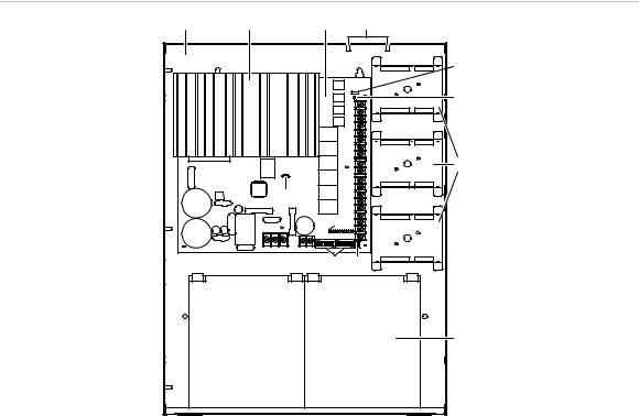
Component descriptions
Figure 1: Components
(1) |
(2) |
(3) |
(4) |
|
|
|
(5) |
|
|
|
(6) |
|
|
|
(7) |
|
|
(12) |
|
|
|
(10) |
|
|
|
(9) |
(8) |
|
|
|
(11) |
(1)Enclosure: Houses the electronics and two standby batteries
(2)Heat sink: Distributes heat away from the circuit board
(3)Circuit board: Provides connections for all circuits
(4)Tamper switch standoffs: 3-TAMP mounting standoffs
(5)Jumper JP3: Ground fault enable or disable option
(6)AC LED: AC power on
(7)Mounting brackets: Option module mounting brackets
(8)Jumpers JP1 and JP2: Class A or Class B NAC option
(9)DIP switches: Two eight-position DIP switches used for configuration
(10)Circuit LEDs: NAC, battery, and ground fault trouble LEDs
(11)Batteries: Up to two 10 Ah batteries fit in the enclosure. For larger batteries, use an external battery cabinet (BC-1 or BC-2).
(12)Jumper JP4: Battery charging jumper
4 |
Remote Booster Power Supply Technical Reference Manual |
Specifications
The following specifications apply to all BPS models.
AC line voltage |
|
6.5 A BPS |
120 VAC / 230 VAC (50/60 Hz), 390 W |
10 A BPS |
120 VAC / 230 VAC (50/60 Hz), 580 W |
|
|
Sense voltage (input) |
6 to 45 VDC (FWR and unfiltered DC) |
|
|
Sense current (input) |
6 mA at 24 VDC, 3 mA at 12 VDC, 12 mA at 45 VDC |
NAC output voltage (special application circuit)
19.1 to 26.40 VDC
Note: All NACs are supervised. Refer to the Remote Booster Power Supply Compatibility List P/N 3100656 for the maximum number of devices that can be used on a NAC circuit.
AUX output voltage |
19.0 to 26.48 VDC |
(special application circuit) |
|
|
|
NAC/AUX output current |
3.0 A max. per circuit with 0.35 power factor |
|
(6.5 A or 10 A max. total for all NACs) |
|
(6 A or 8 A max. total for all AUXs) |
|
|
NAC/AUX capacitive loading |
10,000 F max. for continuous NAC circuits |
|
2,200 F max. for coded rate NAC circuits |
|
2,200 F max. for AUX circuits |
|
|
NAC/AUX class |
Class A or Class B |
|
|
Wire size |
18 to 12 AWG (0.75 to 2.5 mm2) |
NAC EOL |
UL: 15 k (P/N EOL-15) |
|
ULC: Use P/N EOL-P1 and select the 15 k resistor |
|
|
Auxiliary output (continuous) |
1 dedicated unsupervised, unswitched 200 mA auxiliary output |
|
Voltage range: 19.49 to 26.85 VDC |
|
|
Common trouble relay |
Form C, 1 A, 30 VDC (resistive) |
|
|
Battery capacities |
6.5 to 24 Ah for ECS/MNS/LSS applications |
|
6.5 to 24 Ah for Security/Access Control applications |
|
10 Ah maximum in BPS enclosure applications |
|
|
Battery charger current limit [1] |
1.2 A when the battery jumper wire is cut |
|
2.1 A when the battery jumper wire is not cut |
|
|
Operating environment |
|
Operating temperature |
32 to 120°F (0 to 49°C) |
Relative humidity |
0 to 93% noncondensing |
|
|
Ground fault impedance |
10 k |
|
|
Intended installation |
Indoor-dry |
environment |
|
|
|
[1] The battery charger is disabled automatically and will not charge the batteries when the unit is activated via either of its sense inputs.
Remote Booster Power Supply Technical Reference Manual |
5 |

LED indicators
The BPS has seven LED indicators. See “Component descriptions” for the location of the LEDs.
Table 1: LED indicators
LED |
Color |
Description |
|
|
|
AC |
Green |
AC power on. |
|
|
|
NAC1 |
Yellow |
NAC1/AUX1 trouble [1]. |
|
|
|
NAC2 |
Yellow |
NAC2/AUX2 trouble [1]. |
|
|
|
NAC3 |
Yellow |
NAC3/AUX3 trouble [1]. |
|
|
|
NAC4 |
Yellow |
NAC4/AUX4 trouble [1]. |
|
|
|
BAT |
Yellow |
Battery trouble. Indicates that the battery level has fallen below |
|
|
acceptable levels. |
|
|
|
GND |
Yellow |
Ground fault. Indicates that a ground fault has been detected on |
|
|
the field wiring. |
|
|
|
[1] The NAC LEDs indicate a trouble with the load or external wiring on the NAC/AUX circuit. For circuits configured as NACs, this could be an open circuit trouble, short circuit trouble, or an overload trouble.
For short circuit troubles, the NAC does not activate until the short circuit condition is removed.
For overload troubles, an active NAC is shutdown. After shutdown, if there is no short circuit condition, the NAC reactivates after 30 seconds and checks to see if the overload condition still exists.
For AUX circuits, the trouble indicates an overload condition. The AUX circuit is shutdown for 30 seconds and then is reactivated to see if the overload condition still exists.
Trouble indicating and reporting
When the BPS trouble relay is not dedicated to AC power loss reporting (DIP switch SW2-6 OFF), the trouble conditions listed in the table above are reported through the trouble relay. Other internal troubles that do not have an associated LED are also reported via the BPS trouble relay. Other internal troubles include: DIP switch read trouble, RAM failure, code checksum failure, A to D failure, and battery charger failure.
All troubles are also reported through both sense circuit trouble relays.
6 |
Remote Booster Power Supply Technical Reference Manual |
Installing the enclosure
When installing this system, be sure to follow all applicable national and local codes and standards.
The enclosure can be surface mounted or semiflush mounted. See “Enclosure dimensions” below for details.
To surface mount the enclosure:
1.Position the enclosure on the finished wall surface.
2.Fasten the enclosure to the wall surface where indicated.
3.Install all conduits and pull all wiring into the enclosure before proceeding.
To semiflush mount the enclosure:
1.Frame the interior wall as required so that it supports the full weight of the enclosure and standby batteries.
2.Fasten the enclosure to the framing studs where indicated.
3.Install all conduits and pull all wiring into the enclosure before proceeding.
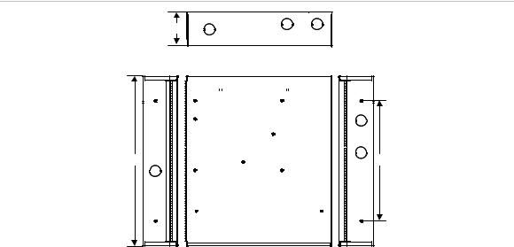
Figure 2: Enclosure dimensions
D5 |
(1) |
 D2
D2 

 D3
D3 


 D4
D4 

(2)
(3)
D1 |
D6 |
(3)
(4)
(1) |
Top view |
|
|
(3) |
Side view |
|
|
(2) |
Front view |
|
|
(4) |
All knockouts are a combination |
||
|
|
|
|
|
0.5 in. (1.27 cm) and 0.75 in. (1.9 cm) |
||
|
|
|
|
|
|
|
|
D1 |
|
D2 |
D3 |
D4 |
|
D5 |
D6 |
|
|
|
|
|
|
||
17.0 in |
3.5 in |
13.0 in |
6.5 in |
3.375 in |
12.0 in |
||
(43.2 cm) |
(8.9 cm) |
(33.0 cm) |
(16.5 cm) |
(8.6 cm) |
(30.4 cm) |
||
|
|
|
|
|
|
|
|
Remote Booster Power Supply Technical Reference Manual |
7 |

Installing option modules in the enclosure
Up to three option modules can be installed on the mounting brackets inside the enclosure. Depending on the model, the device must be either screw-mounted or snap-mounted to the bracket.
To snap-mount modules on a bracket:
1.Snap the module into a mounting bracket.
2.Connect all wiring. Refer to the module’s installation sheet for wiring information or to the Signature Series Component Installation Manual
(P/N 270497).
Note: Route the wiring around the perimeter of the enclosure, not across the circuit board.
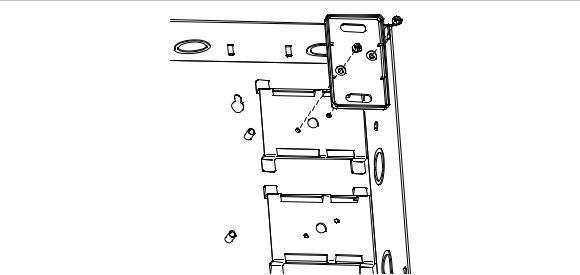
Figure 3: Mounting brackets with an option module
(1) |
(2) |
(1)Mounting brackets
(2)Option module
To screw-mount Signature Series modules on a bracket:
1.Remove the module’s plastic cover.
2.Remove the circuit board from the plastic backing.
3.Screw the plastic backing to the mounting bracket using two #6, 1/4 flat head sheet metal screws. See Figure 4 on page 9.
Note: For mounting MN-NETRLY4 modules, refer to the MN-NETRLY4 Network Relay Module Installation Sheet, P/N 310-1827-ML.
4.Insert the circuit board into the plastic backing.
5.Snap the module’s plastic cover into place.
6.Connect all wiring. Refer to the module’s installation sheet for wiring information or to the Signature Series Component Installation Manual
(P/N 270497).
8 |
Remote Booster Power Supply Technical Reference Manual |
Note: Route the wiring around the perimeter of the enclosure, not across the circuit board.
Figure 4: Inserting the circuit board
Remote Booster Power Supply Technical Reference Manual |
9 |

Installing the circuit board in the enclosure
You may have to remove the circuit board to install the enclosure. Reinstalling the circuit board in the enclosure must be done with accuracy to avoid causing ground faults or shorts. The screws and standoffs must be installed correctly and in the right positions. Use the diagrams below to install the circuit board.
Figure 5: Complete circuit board installation
(4)
(3)
(2) 
(1)
(6) |
(5) |
(7)
(1)Cover (“C” models, only)
(2)Long screws
(3)Circuit board
(4)Enclosure
(5)Enclosure standoffs
(6)Barrel spacers, see Figure 6 on page 11
(7)Short screws
10 |
Remote Booster Power Supply Technical Reference Manual |

Figure 6: Barrel spacer installation
(1) 

(2)
(1)Barrel spacers
(2)Long screws
Note: The barrel spacers must be positioned correctly so that the long screw can pass through the spacer and into the enclosure standoff.
Remote Booster Power Supply Technical Reference Manual |
11 |

Setting the jumpers
There are four jumpers on the BPS. See Figure 1 on page 4 for the location of the jumpers.
NAC Class A or Class B (JP1 and JP2)
JP1 and JP2 are used to select a Class A or Class B NAC wiring configuration for all NACs. The default is Class B.
Note: JP1 and JP2 must be positioned to match the SW2-8 DIP switch selection (Class A or Class B).
Figure 7: JP1 and JP2
1 |
(1) |
1 |
(1) |
|
2 |
2 |
|||
(2) |
(2) |
|||
3 |
3 |
|||
|
|
|||
|
JP1 |
|
JP2 |
(1)Class A
(2)Class B
Ground fault enable (JP3)
JP3 is used to set the NAC/AUX circuits for ground fault enabled or disabled operation. The sense inputs are always isolated from local power.
Enabled: Allows the BPS to perform its own ground fault checking. This is the default position.
Disabled: Disable the BPS's ground fault detection only when the controlling panel is providing ground fault detection for the BPS output circuits. See Figure 8 on page 13 for wiring information.
12 |
Remote Booster Power Supply Technical Reference Manual |
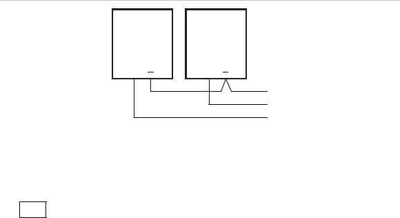
Figure 8: Ground fault enable
(1) |
(2) |
+ +
(3)
(1)Control panel. The control panel is responsible for ground fault detection when the BPS is wired in this fashion.
(2)BPS. Disable the BPS’s ground fault jumper (JP3).
(3)To next BPS that requires ground fault detection from the control panel.
JP3 
 1 2
1 2
GF disable: Do not install jumper
GF enable: Install jumper
Battery charging (JP4)
The battery charging jumper is a small wire that controls how the batteries are charged. Battery size determines whether you must cut the jumper wire or leave it intact.
JP4 

Cut the jumper wire when using batteries under 10 Ah.
Do not cut the jumper wire when using batteries 10 Ah or over.
Remote Booster Power Supply Technical Reference Manual |
13 |

UL 864 programming requirements
NOTICE TO USERS, INSTALLERS, AUTHORITIES HAVING JURISDICTION, AND OTHER INVOLVED PARTIES
This product incorporates field-programmable options. In order for the product to comply with the requirements in the Standard for Control Units and Accessories for Fire Alarm Systems, UL 864, certain programming features or options must be limited to specific values or not used at all as indicated below. Some options were permitted under the previous versions of UL 864 and are provided to allow for service replacements on those systems.
Programmable feature or |
Permitted in |
Possible settings |
Settings permitted |
option |
UL 864? (Y/N) |
|
in UL 864 |
|
|
|
|
Four second NAC audible |
N |
On (4 second delay) |
Off |
synchronization delay [1] |
|
Off (1 second delay) |
|
|
|
|
|
AC power delay |
Y |
On (3 hour, no |
On |
|
|
dedicated AC failure |
|
|
|
contact) |
|
|
|
Off (no delay) |
|
[1] This option is controlled by switch SW1-4. See “Synchronization control (SW1-4)” on page 16.
14 |
Remote Booster Power Supply Technical Reference Manual |
 Loading...