

Page 1

A590-00-880
Issue D Original
Instruction Manual
iH Dry Pumping Systems
Description Item Number
iH80 A590-00-xxx
iH160 A590-10-xxx
iH160HTX A590-12-xxx
iH600 A590-20-xxx
iH1000 A590-30-xxx
iH1800 A590-40-xxx
iH1800HTX A590-42-xxx
iH1800NRV A590-50-xxx
iH1800NRV HTX A590-52-xxx
Where xxx is as follows:
460 V, 60 Hz, 3 phase 908
200/208 V, 50/60 Hz, 3 phase 945
380/415 V, 50 Hz, 3 phase 946
230 V, 60 Hz, 3 phase 957
Page 2

This product has been manufactured under a quality system registered to ISO9001
Declaration of Conformity
We, Edwards,
Manor Royal,
Crawley,
West Sussex, RH10 9LW, UK
declare under our sole responsibility, as manufacturer and person within the EU authorised
to assemble the technical file, that the product(s)
Standard HTX Where xxx is as follows:
iH80 A590-00-xxx
iH600 A590-20-xxx 908 – 460V, 60Hz, 3-phase
iH1000 A590-30-xxx 945 – 200/208V, 50/60Hz, 3-phase
iH160 A590-10-xxx A590-12-xxx 946 – 380/415V, 50Hz, 3-phase
iH1800 A590-40-xxx A590-42-xxx 957 – 230V, 60Hz, 3-phase
iH1800 NRV A590-50-xxx A590-52-xxx
iH interface Module fitting kit A505-35-000
iH enclosure extraction fan (for iH80 and iH600 only) A505-39-000
iH Light Duty exhaust check valve A505-56-000
to which this declaration relates is in conformity with the following standard(s) or other
normative document(s)
EN1012-2:1996, A1: 2009 Compressors and Vacuum Pumps. Safety Requirements.
Vacuum Pumps
EN61010-1: 2001 Safety Requirements for Electrical Equipment for Measurement,
Control and Laboratory Use. General Requirements
EN 61326-1: 2006 E l ectrical equipment for measurement, control and laboratory
Use. EMC requirements. General requirements.
UL61010A: 2002 Safety requirements for electrical equipment for measurement,
Control and laboratory use – Part 1: General requirements
SEMI S2-93A Environmental Health and Safety Guideline for semiconductor
Manufacturing Equipment.
and fulfils all the relevant provisions of
2006/42/EC Machinery Directive
2006/95/EC Low Voltage Directive
2004/108/EC Electro magnetic Compatibility (EMC) Directive
Note: This declaration covers all product serial numbers from the date this Declaration was
signed onwards.
Sia Abbaszadeh, Chief Technical Officer
Date and Place
P200-00-960 Issue B
9 December 2009
Page 3

Page 4

This page has been intentionally left blank.
Page 5

© Edwards Limited 2008. All rights reserved. Page i
Edwards and the Edwards logo are trademarks of Edwards Limited.
Contents
A590-00-880 Issue D
Contents
Section Page
1 Introduction ....................................................................................... 1
1.1 Scope and definitions ................................................................................................... 1
1.2 Applications ............................................................................................................... 2
1.3 Description ................................................................................................................ 3
1.3.1 The iH HTX system ....................................................................................................... 3
1.3.2 The iH NRV systems ..................................................................................................... 3
1.4 Priority of control ........................................................................................................ 3
2 Technical data .................................................................................... 7
2.1 General technical data .................................................................................................. 7
2.2 Electrical data ............................................................................................................ 9
2.3 Loading ...................................................................................................................10
2.4 Connections ..............................................................................................................11
2.5 General data ............................................................................................................. 12
3 Installation ....................................................................................... 13
3.1 Locate the dry pumping system ......................................................................................14
3.2 Lubrication ...............................................................................................................15
3.3 Connect the dry pumping system to your vacuum/exhaust system ............................................. 15
3.4 Connect the iH1800HTX exhaust TMS ................................................................................16
3.5 Connect to your factory extraction system (optional) ............................................................16
3.6 Connect the nitrogen supply ..........................................................................................17
3.6.1 Flammable/pyrophoric materials ....................................................................................17
3.6.2 Gas purges ...............................................................................................................18
3.7 Leak-test the system ...................................................................................................18
3.8 Electrical supply ........................................................................................................18
3.8.1 Reconfigure the iH system for your electrical supply (if necessary) ............................................ 19
3.8.2 Reconfigure the iH system for your electrical supply (iH80/600 only) .........................................19
3.8.3 Connect the electrical supply .........................................................................................21
3.9 Connect an additional RF earth (ground) (optional) .............................................................. 23
3.10 Connect to your emergency stop circuit ............................................................................23
3.11 Connect the cooling-water hoses .....................................................................................24
3.12 Accessories ...............................................................................................................24
3.13 Commission the system ................................................................................................25
3.14 Install additional safety equipment ..................................................................................26
4 Operation ........................................................................................ 27
4.1 Start-up ..................................................................................................................27
4.2 Status indicators ........................................................................................................28
4.3 Manual shut-down ...................................................................................................... 28
4.4 Automatic shut-down .................................................................................................. 29
4.5 Unplanned shutdown and alarms ..................................................................................... 29
4.6 Emergency stop .........................................................................................................30
4.7 Restart the pump after an emergency stop or automatic shut-down .......................................... 30
4.8 Single equipment monitor (SEM) ..................................................................................... 30
5 Maintenance ..................................................................................... 31
5.1 Safety and maintenance frequency ..................................................................................31
5.2 Relocate the system for maintenance ............................................................................... 32
5.3 Cleaning the pump ......................................................................................................33
5.4 General maintenance ..................................................................................................33
dcs/8119/08/08
Page 6

A590-00-880 Issue D
Page ii © Edwards Limited 2008. All rights reserved.
Edwards and the Edwards logo are trademarks of Edwards Limited.
Contents
5.5 Replace a fuse ........................................................................................................... 34
5.6 Inspect the connections, pipelines, cables and fittings .......................................................... 34
6 Transportation, storage and disposal ........................................................ 35
6.1 Transportation ..........................................................................................................35
6.2 Storage ...................................................................................................................35
6.3 Disposal ................................................................................................................... 35
7 Service, spares and accessories .............................................................. 37
7.1 Introduction .............................................................................................................37
7.2 Service .................................................................................................................... 37
7.3 Ordering accessories ...................................................................................................37
For return of equipment, complete the HS Forms at the end of this manual.
Illustrations
Figure Page
1 iH applications chart .................................................................................................... 2
2 Priority of control ........................................................................................................ 3
3 The controls/connectors on rear of pump ........................................................................... 4
4 The controls/connectors on electrics box ........................................................................... 4
5 Top view of pump ........................................................................................................ 5
6 The front panel controls ................................................................................................ 5
7 Centre of gravity and levelling foot loads ..........................................................................10
8 System arrangement to reduce effective footprint (if required) ............................................... 14
9 Reconfigure the iH system for your electrical supply .............................................................20
10 Reconfigure the pump-motor terminal-boxes (iH80/iH600 only) ................................................21
11 Connect the electrical supply cable to the connector mating-half ............................................. 23
Tables
Table Page
1 Technical data iH80, iH600 and iH1000 .............................................................................. 7
1 Technical data iH160 and iH1800 ..................................................................................... 8
2 Technical data ........................................................................................................... 8
3 Electrical data 200-208 V 50 Hz-230 V 60 Hz ........................................................................ 9
3 Electrical data 380-415 V 50 Hz-460 V 60 Hz ........................................................................ 9
4 Centre of gravity and levelling foot loads (Refer to Figure 7) ................................................... 10
5 iH connector types ......................................................................................................11
6 Technical data .......................................................................................................... 12
7 Safety sensors ...........................................................................................................29
8 Accessories ...............................................................................................................37
Associated publications
Publication title Publication number
Vacuum Pump and Vacuum System Safety P300-20-000
Semiconductor Pumping Application Guide P411-00-090
Page 7

© Edwards Limited 2008. All rights reserved. Page 1
Edwards and the Edwards logo are trademarks of Edwards Limited.
Introduction
A590-00-880 Issue D
1Introduction
1.1 Scope and definitions
This manual provides installation, operation and maintenance instructions for the Edwards iH dry pumping systems.
You must use your pumping system as specified in this manual.
Read this manual before you install and operate your pump. Important safety information is highlighted as WARNING
and CAUTION instructions; you must obey these instructions. The use of WARNINGS and CAUTIONS is defined below.
CAUTION
Cautions are given where failure to observe the instruction could result in damage to the equipment, associated
equipment and/or process.
The units throughout this manual conform to the SI international system of units of measurement.
In accordance with the recommendations of IEC1010, the following warning labels are on the pump:
WARNING
Warnings are given where failure to observe the instruction could result in injury or death to
people.
Warning - refer to accompanying documentation. Warning - moving parts present.
Warning - risk of electric shock. Warning - heavy object.
Warning - hot surfaces. RF earth (ground).
Protective earth (ground). Warning - pressurised.
Page 8

A590-00-880 Issue D
Page 2 © Edwards Limited 2008. All rights reserved.
Edwards and the Edwards logo are trademarks of Edwards Limited.
Introduction
The Pressurised and Risk of explosion warnings only appear in this manual.
Material Safety Data Sheets for chemicals supplied by Edwards can be obtained by contacting Edwards.
1.2 Applications
If you use the iH system on an application for which it is not suitable (refer to Figure 1), you may invalidate your
warranties. If in doubt, contact Edwards who will advise you as to the suitability of the iH system for any particular
application.
Figure 1 - iH applications chart
Note: This product is not ATEX compliant, a range of ATEX compliant pumping systems are available, contact
Edwards for details.
Warning - use protective equipment. Warning - Risk of explosion.
Page 9

© Edwards Limited 2008. All rights reserved. Page 3
Edwards and the Edwards logo are trademarks of Edwards Limited.
Introduction
A590-00-880 Issue D
1.3 Description
1.3.1 The iH HTX system
For enhanced performance on harsh duty processes, especially those prone to condensation of process gases inside
the pumping system. This is achieved by:
z Increased dry pump operating temperature
z Increased gas purge capacity
z Increased exhaust diameter and exhaust TMS (Thermal Management System)
z Provision for optional heated exhaust purge.
1.3.2 The iH NRV systems
For Flat Panel Display processes.
1.4 Priority of control
The system can be controlled by a number of modules: the Pump Display Terminal (PDT), from the tool through the
IM interface and communications module, iTIM, or from the Single Equipment Monitor (refer to Figure 3). Only one
of these can have control of the iH system at any one time. That is, once one of these has control of the iH system,
control requests from the others are denied.
The PDT indicates who is in control. LEDs are also provided on the rear panel, front panel or PDT, which illuminate
to indicate 'in control'. Please refer to Figure 2.
Figure 2 - Priority of control
1. PDT
2. iM
3. iTIM
4. None in control
Take
Release
Page 10

A590-00-880 Issue D
Page 4 © Edwards Limited 2008. All rights reserved.
Edwards and the Edwards logo are trademarks of Edwards Limited.
Introduction
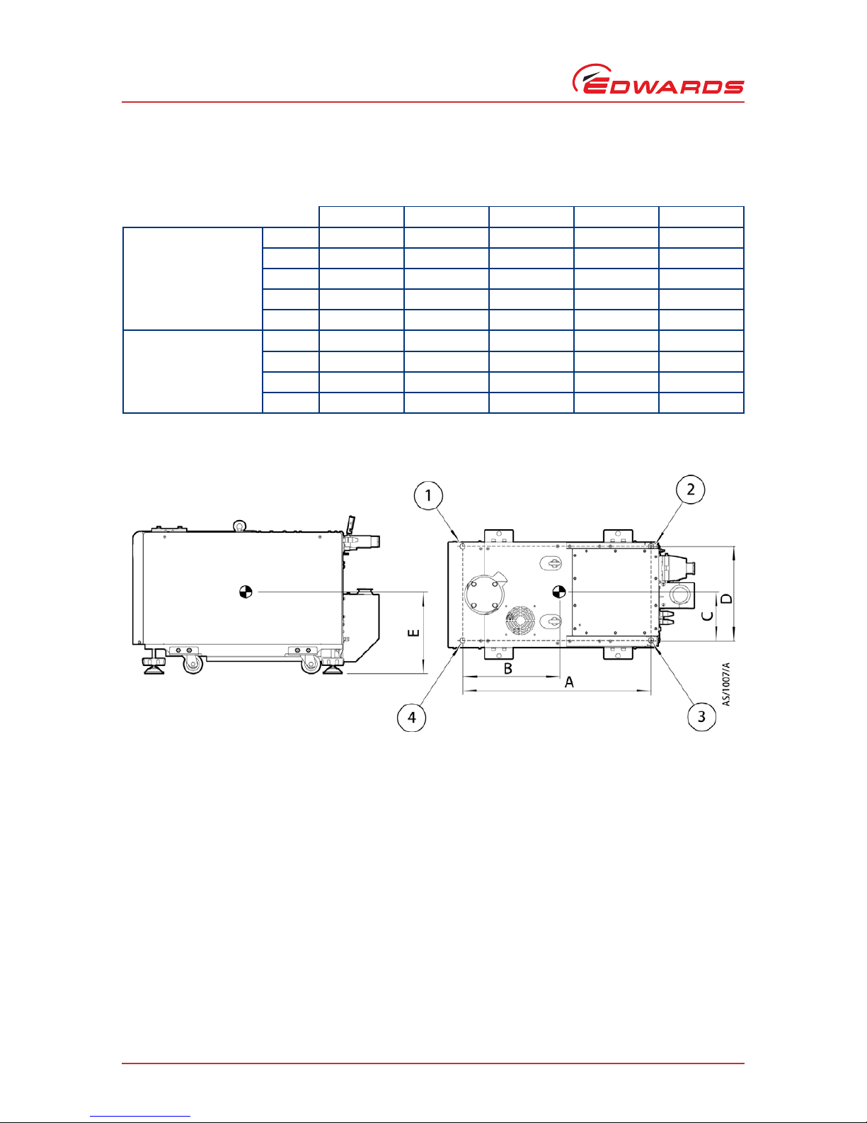
Figure 3 - The controls/connectors on rear of pump
Figure 4 - The controls/connectors on electrics box
1. Electrical box
2. Exhaust check valve
3. Cooling-water supply connection
4. Seismic bracket (4 off)
5. RF earth (ground) stud M6
6. Cooling-water return connection
7. Levelling feet (4 off)
8. Nitrogen purge port
9. Castor (4 off)
10. Exhaust enclosure
11. Active gauge connection
12. iTIM connection
13. Rear cover
1. Protective earth (ground) stud M5
2. Exhaust gas outlet connection
3. d.c. Electrical supply fuse holder (F10)
4. Emergency stop fuse holder (F9)
5. Tool interface module fuse holder (F8)
6. Rear Power on lamp
7. EMS/Tool interface module connection
8. LON module connection
9. Electrical supply connection
Page 11

© Edwards Limited 2008. All rights reserved. Page 5
Edwards and the Edwards logo are trademarks of Edwards Limited.
Introduction
A590-00-880 Issue D
Figure 5 - Top view of pump
Figure 6 - The front panel controls
1. Inverter
*
2. Extraction port
3. Lifting eyebolts (2 off)
4. RF earth (ground) cable
*
iH160/1000/1800 only.
5. Pumped gas inlet connection
6. Leak-test port (combination)
7. Leak-test port (pump only)
1. EMS button
2. Running LED (green)
3. Power OK LED (green)
4. Pump display terminal connection
5. LON module connection
6. Alarm LED (red)
7. Warning LED (amber)
Page 12

A590-00-880 Issue D
Page 6 © Edwards Limited 2008. All rights reserved.
Edwards and the Edwards logo are trademarks of Edwards Limited.
This page has been intentionally left blank.
Page 13

© Edwards Limited 2008. All rights reserved. Page 7
Edwards and the Edwards logo are trademarks of Edwards Limited.
Technical data
A590-00-880 Issue D
2Technical data
2.1 General technical data
Table 1 - Technical data iH80, iH600 and iH1000
Type Characteristics iH80 iH600 iH1000 Units
General Dimensions (L (to exhaust enclosure)
x W x H (to inverter))
*
*
Refer to Web for installation drawings.
776 (909) x
390 x 529
776 (909) x
390 x 839
776 (909) x
390 x 839
(992)
mm
Mass (excluding packaging) 240 415 430 kg
Noise level (ultimate) < 64 < 67 < 69 dB(A)
Vibration level at inlet < 1.8 < 1.8 < 1.8 mm s
-1
Initial force to push the pump 8 16 20 kg
Sustained force to push the pump 5 7 8 kg
Earth leakage <1.1 <1.1 <3 mA
Warm up time to nominal pumping
performance
15 15 15 minutes
Minimum warm up time to process
gas pumping
444hours
Performance
50 Hz / 60 Hz
Typical peak pumping speed 86 / 103 518 / 600 950 / 1000 m
3 h-1
Ultimate (shaft seal purge only) 3 x 10⁻²/
1 x 10
-2
2 x 10⁻³/
7 x 10
-4
2 x 10⁻³/
1 x 10
-3
mbar
Maximum inlet pressure Atmospheric Atmospheric Atmospheric
Maximum operating time at
maximum inlet pressure
Continuous 1 Continuous hour
Water cooling
system
Minimum flow rate required 2 4 4 l min
-1
Typical heat removed from the
system
2.5 3.2 3.2 kW
Connections Pump inlet flange (bolted) ISO63 ISO100 ISO100
Exhaust gas outlet NW40 NW40 NW40
Extraction port 105 105 105 mm dia
Page 14

A590-00-880 Issue D
Page 8 © Edwards Limited 2008. All rights reserved.
Edwards and the Edwards logo are trademarks of Edwards Limited.
Technical data
Table 1 - Technical data iH160 and iH1800
Type Characteristics iH160 iH1800 Units
General Dimensions (L (to exhaust enclosure)
x W x H (to inverter))
*
*
Refer to Web for installation drawings.
776 (909) x 390
x 529 (783)
986 (1059) x 470
x 888 (1094)
mm
Mass (excluding packaging) 244 502 kg
Noise level (ultimate) <64 <69 dB(A)
Vibration level at inlet <1.8 <1.8 mm s
-1
Initial force to push the pump 8 25 kg
Sustained force to push the pump 5 10 kg
Earth leakage < 3.8 < 6.8 mA
Warm up time to nominal pumping
performance
15 15 minutes
Minimum warm up time to process
gas pumping
44hours
Perfo rmance
50 Hz / 60 Hz
Typical peak pumping speed 165 1800 m
3 h-1
Ultimate (shaft seal purge only) 1x10
-2
1x10
-3
mbar
Maximum inlet pressure Atmospheric Atmospheric
Maximum operating time at
maximum inlet pressure
Continuous Continuous hour
Water cooling
system
Minimum flow rate required 2 4 l min
-1
Typical heat removed from the
system
2.5 3.2 kW
Connections Pump inlet flange (bolted) ISO63 ISO160
Exhaust gas outlet NW40 NW40
Extraction port 105 50 mm dia
Tab l e 2 - Tec h ni cal d ata
Typ e C h a racteris ticsAllHTX onlyUnits
Gas system Nitrogen supply pressure range 1.4 to 6.9 3.8 to 6.9 bar gauge
Stability of supply +/-2.4 +/-2.4 bar gauge
Nitrogen supply quality < 0.01 < 0.01 µm
Nitrogen flow rate 44 76 slm
Gas module pressure range 1 1 bar gauge
Pressure transducer accuracy +/-0.0041 at 0.4 +/-0.0041 at 0.4 bar gauge
Page 15

© Edwards Limited 2008. All rights reserved. Page 9
Edwards and the Edwards logo are trademarks of Edwards Limited.
Technical data
A590-00-880 Issue D
2.2 Electrical data
Table 3 - Electrical data 200-208 V 50 Hz-230 V 60 Hz
Supply voltage and frequency
200-208 V
50 Hz
200-208 V
60 Hz
230 V
60 Hz
iH80 / iH160 HCDP Full load (Amp) 14.4 14.9 14.4
Motor rating (kW) 2.9 3.5 3.5
Max power input to motor (kW) 3.65 4.48 4.48
iH600 / iH1000 HCDP Full load (Amp) 14.4 14.9 14.4
Motor rating (kW) 2.9 3.5 3.5
HCMB Full load (Amp) 11.8 11.8 11.7
Motor rating (kW) 2.2 2.6 2.6
Max power input to both motors (kW) 6.51 7.8 7.8
iH1800 HCDP Full load (Amp) 14.4 14.9 14.4
Motor rating (kW) 2.9 3.5 3.5
HCMB Full load (Amp) 14.4 14.9 14.4
Motor rating (kW) 2.9 3.5 3.5
Max power input to both motors (kW) 7.3 8.96 8.96
Table 3 - Electrical data 380-415 V 50 Hz-460 V 60 Hz
Supply voltage and frequency
380-415 V
50 Hz
460 V
60 Hz
iH80 / iH160 HCDP Full load (Amp) 7.2 7.2
Motor rating (kW) 2.9 3.5
Max power input to motor (kW) 3.65 4.48
iH600 / iH1000 HCDP Full load (Amp) 7.2 7.2
Motor rating (kW) 2.9 3.5
HCMB Full load (Amp) 5.9 5.8
Motor rating (kW) 2.2 2.6
Max power input to both motors (kW) 6.51 7.8
iH1800 HCDP Full load (Amp) 7.2 7.2
Motor rating (kW) 2.9 3.5
HCMB Full load (Amp) 7.2 7.2
Motor rating (kW) 2.9 3.5
Max power input to both motors (kW) 7.3 8.96
Page 16
A590-00-880 Issue D
Page 10 © Edwards Limited 2008. All rights reserved.
Edwards and the Edwards logo are trademarks of Edwards Limited.
Technical data
2.3 Loading
Figure 7 - Centre of gravity and levelling foot loads
Table 4 - Centre of gravity and levelling foot loads (Refer to Figure 7)
iH80 iH600 iH1000 iH160 iH1800
Centre of gravity A 661 661 661 661 661
B 322 309 314 304 325
C 159 163 163 163 198
D 302 302 302 302 382
E 293 466 481 364 528
Levelling loads 1 75 103 118 70 133
26611911565125
351759050113
44811810760132
Page 17

© Edwards Limited 2008. All rights reserved. Page 11
Edwards and the Edwards logo are trademarks of Edwards Limited.
Technical data
A590-00-880 Issue D
2.4 Connections
Table 5 - iH connector types
Description
Mating connector description / external
supply rating
Internal supply
rating
Electrical supply connector Harting HAN-K-4/2 16 mm
2
wire, 18 to
27 mm cable OD
1 - Phase 1 (R)
2 - Phase 2 (S)
3 - Phase 3 (T)
Pump display terminal connector XLR type 5-way plug 24 V d.c. 0.75 A
Network LON communications connector XLR type 4-way plug 24 V d.c. 0.75 A
Exhaust gas management interface DIN type 6-pin plug
1 - normally open and 3 - common 30 V a.c. 1 A
2 - normally open and 4 - normally closed 30 V a.c. 1 A
3 - normally open and 6 - common 60 V d.c. 0.5 A
Active gauge connector
*
*
Optional accessory.
SCC68 socket
Exhaust TMS power supply
†
†
HTX variants only.
Edwards TMS type
Tool interface module connector / EMS XLR type 6-way plug
1 and 2 - linked, remove - normally closed
3 and 4 - isolated auxiliary contacts
5 - continuous output 24 V a.c. 625 mA
6 - return
Tool interface adapter (iTIM) D type 15-way plug
External emergency stop switch 24 V a.c. 5 A
(load 700 mA
inductive)
Page 18

A590-00-880 Issue D
Page 12 © Edwards Limited 2008. All rights reserved.
Edwards and the Edwards logo are trademarks of Edwards Limited.
Technical data
2.5 General data
Tab l e 6 - Tec h ni cal d ata
Item Description Rating Units
Electrical Supply voltage 3-phase 200-208/380 - 415 V, 50 Hz a.c.
200-208/230/460 V, 60 Hz a.c.
Recommended fuse / isolator
rating
Full load current rating, refer to
Ta bl e 3
Class CC fuse rated to 600V.
Voltage tolerance range +/- 10% V
208 V and 415 V, 50 Hz only +6% /-10% V
Installation category II (IEC 664)
Harmonic voltage distortion factor 5%
Fuse types and ratings
F8 T1.6 A, 250 V
F9 T3.15 A, 250 V
F10 T5.0 A, 250 V
Water cooling system Maximum supply pressure 100 psig
Minimum supply pressure 36 psig
Minimum flow rate required Refer to Ta bl e 1
Supply temperature range 10-30 °C
Typical pressure differential across
supply and return
*
*
With cooling water supply temperature of 20°C and flow rate of 3 l min-1.
15 psig
Water type Treated or non-corrosive industrial
Maximum particle size 0.03 mm
2
Acidity 6.5 to 8.0 pH
Hardness <100 ppm
Resistivity >1 k cm
Solids (turbidity) <100 ppm
Materials in contact with cooling
water
Stainless steel, Nitrile, PTFE, copper,
brass and fluoroelastomer
Connections Water cooling inlet 3/8 inch BSP male quick connector
Water cooling outlet 3/8 inch BSP female quick connector
Nitrogen inlet 1/4 inch tube fitting
Materials in contact
with process gas
Pump, shaft and rotors Cast Iron, Steel, SG iron
Seals PTFE and fluoroelastomer
Gas System Stainless steel, Aluminium, brass and
fluoroelastomer
Operating conditions Intended use Indoor
Ambient temperature range:
Operating 5 to 40 °C
Storage -45 to 55 °C
Relative humidity 10 to 90 %RH
Maximum operating altitude 2000 m
Pollution degree 2 (IEC 61010)
Page 19

© Edwards Limited 2008. All rights reserved. Page 13
Edwards and the Edwards logo are trademarks of Edwards Limited.
Installation
A590-00-880 Issue D
3 Installation
Potential hazards on the dry pumping system include electricity, hot surfaces, process chemicals, Fomblin oil,
nitrogen and water under pressure.
Detailed safety information is given in Section 4 and Edwards Publication Number P300-20-000 'Vacuum Pump and
Vacuum System Safety'.
z Only Edwards engineers may install the dry pumping system. Users can be trained by Edwards to conduct the
tasks described in this manual, contact your local service centre or Edwards for more information.
z Do not remove the temporary cover or blanking plate from the dry pumping system inlet and exhaust until
you are ready to connect the dry pumping system to your vacuum or exhaust-extraction system. Do not
operate the dry pumping system unless the inlet and exhaust are connected to your vacuum and exhaustextraction system.
z Vent and purge the process system (if the dry pumping system is to replace an existing pumping system) with
nitrogen for 15 minutes before you start installation work. Refer to Section 5.
z Disconnect the other components in the process system from the electrical supply so that they cannot be
operated accidentally.
z Electrical, nitrogen and water supplies are all potentially hazardous energy sources. Before carrying out any
maintenance the supply of these sources should be locked and tagged out.
z The pump system includes provision for ventilation extraction and secondary containment of oil and water
leaks. Any unintended overflows or spills must be removed immediately to avoid risk of slips.
z Obey all national and local rules and safety regulations when you install the dry pumping system. Consult
Edwards Publication Number P300-20-000 (Vacuum Pump and Vacuum System Safety) before you pump
hazardous materials. This publication is available on request: contact your supplier or Edwards.
z Route and secure cables, hoses and pipework during installation to avoid possible risk of trips.
z Be aware the exhaust TMS can be live and maintaining a high temperature of 150°C, even if the pumping
system power supply is isolated. Disconnect the pump system TMS if the pump is switched off and
disconnected.
WARNING
Obey the safety instructions given below and take the appropriate precautions. If you do not, you
can cause injury to people and damage to equipment.
WARNING
The system should not be operated with the Edwards panels removed.
WARNING
The iH1800HTX has two separate power supplies, one for the pump system and the other for the
exhaust TMS.
Page 20
A590-00-880 Issue D
Page 14 © Edwards Limited 2008. All rights reserved.
Edwards and the Edwards logo are trademarks of Edwards Limited.
Installation
3.1 Locate the dry pumping system
Use the following procedure to locate the iH system in its operating position. The iH system must be located on a
firm, level surface, to ensure that the system is not damaged.
1. Use suitable lifting equipment attached to the lifting eyebolts (Figure 5, item 3) to move the iH system close to
its final operating position.
2. Adjust the levelling feet (Figure 3, item 7) to make sure that the iH system is level and is not supported by the
castors.
3. If required, the iH system can be secured to the floor by fitting suitable bolts or studs (not supplied) through the
M10 docking points on the chassis. If vibration transmission to the floor is a concern, suitable vibration isolators
(not supplied) should be fitted between the docking points and the bolt or stud, if doing this the levelling feet
will need to be removed.
4. If preferred, the lifting eyebolts can be removed and replaced with the lifting eyebolt hole plugs supplied with
the systems.
5. Ensure that access is possible to the emergency stop button (refer to Figure 6, item 1), if not use an iH
Disconnect Box (refer to Section 7.3).
Figure 8 - System arrangement to reduce effective footprint (if required)
WARNING
You must use suitable lifting equipment to move the system. It is too heavy to lift by hand.
WARNING
Do not exceed the topple angle of 10° when moving the pump. Wheel the system on its castors to
move it into its operating position. The system should only be wheeled short distances over flat
surfaces. If the floor surface is uneven or has obstacles the system should be lifted with suitable
lifting equipment.
WARNING
Ensure that the maximum angle between paired slings used to lift the iH system is 45°.
Page 21
© Edwards Limited 2008. All rights reserved. Page 15
Edwards and the Edwards logo are trademarks of Edwards Limited.
Installation
A590-00-880 Issue D
If you want to secure the iH in place to prevent inadvertent movement (for example, during an earthquake), take
note of the following:
z The iH system seismic brackets (Figure 3, item 4) are designed to withstand a level 4 earthquake in a ground
floor installation.
z The iH system can be secured to the floor by fitting suitable bolts or studs (not supplied) through the
17.5 mm hole in the seismic brackets.
z If vibration transmission to the floor is a concern, suitable vibration isolators (not supplied) should be fitted
between the seismic brackets and the bolt or stud.
z Although the iH system is supplied with four seismic brackets, two brackets are capable of protecting the
system during an earthquake. The system can therefore be secured as shown in Figure 8 for example, to
reduce the effective system footprint if required.
If all four seismic brackets are to be used, ensure that the bolt spacing is adequate for the floor strength and loads
anticipated.
3.2 Lubrication
CAUTION
Ensure that the oil-levels in the HCDP pump and the HMB pump are correct. If a pump oil-level is incorrect, pump
performance may be affected and the pump may be damaged.
The iH system is given a charge of oil before it leaves the factory. There is no requirement to adjust the oil level.
3.3 Connect the dry pumping system to your vacuum/exhaust
system
CAUTION
Use a catchpot to prevent the drainage of condensate back into the iH system. Condensate that drains back into
the iH could damage the HCDP pump.
Do not reuse any O-ring or O-ring assembly and do not allow debris to get into the iH system during installation.
When you connect your iH system to your vacuum system, take note of the following:
z To get the best pumping speed, ensure that the pipeline which connects the vacuum system to the iH system
is the minimum length possible and has an internal diameter not less than the iH system inlet-port.
z Ensure that all components in the vacuum pipeline have a maximum pressure rating which is greater than the
highest pressure that can be generated in your system.
WARNING
Pipe the exhaust to a suitable treatment plant to prevent the discharge of dangerous gases or
vapours to the surrounding atmosphere.
WARNING
Do not operate the system with the exhaust pipeline blocked. If the exhaust pipeline is blocked,
the system can generate exhaust pipeline pressures of up to 7 bar (7 x 10
5
Pa).
Page 22

A590-00-880 Issue D
Page 16 © Edwards Limited 2008. All rights reserved.
Edwards and the Edwards logo are trademarks of Edwards Limited.
Installation
z Incorporate flexible pipelines in the vacuum pipeline to reduce the transmission of vibration and to prevent
loading of coupling-joints. We recommend that you use Edwards braided flexible pipelines. The pipelines
should be suitable for 110 °C.
z Adequately support vacuum/exhaust pipelines to prevent the transmission of stress to pipeline
coupling-joints.
z Incorporate a pressure gauge in the inlet pipeline, so that you determine that the iH system operates
correctly.
z You must be able to isolate the iH system inlet from the atmosphere and from your vacuum system if you
have pumped or produced corrosive chemicals.
z The outlet of the exhaust pipe can have a check-valve fitted which prevents the suck-back of exhaust
vapours after the iH system is shutdown. The check-valve also provides additional attenuation of the pulses
in exhaust pressure.
z On very dusty applications, use a low-impedance inlet-filter to minimise damage to the pump.
z The exhaust pipelines should be suitable for 150 °C for HTX systems.
1. Remove the temporary cover or blanking plate from the inlet of the iH system. Retain the nuts, bolts, washers
and blanking plate for future use. Retain the temporary cover for future use on non-contaminated pumps only.
2. Use the O-ring supplied and suitable nuts, bolts and washers (not supplied) to connect the inlet-flange (Figure 5,
item 5) of the iH system to your vacuum system.
3. Use the NW40 trapped O-ring and clamp supplied to connect the exhaust outlet (Figure 3, item 2) on the exhaust
pipe, to your exhaust extraction system. If check valve/elbow are not required for your application refer to the
web.
3.4 Connect the iH1800HTX exhaust TMS
Refer to Edwards instruction manual Y140-00-880 'TMS Temperature Management System' for details. A separate
power supply can be ordered if required, refer to Section 7.3 for details.
3.5 Connect to your factory extraction system (optional)
Refer to Figure 5, item 2.
WARNING
Ensure that the exhaust TMS is connected to the electrical supply through a suitably rated isolator/
connector.
Page 23

© Edwards Limited 2008. All rights reserved. Page 17
Edwards and the Edwards logo are trademarks of Edwards Limited.
Installation
A590-00-880 Issue D
3.6 Connect the nitrogen supply
CAUTION
Ensure that your nitrogen supply conforms to the requirements given in the Technical Data Section. If it doesn't,
the flow sensors may not operate correctly, the gas pipelines may become blocked or the iH system may be
damaged.
Refer to Figure 3, item 8.
For optimum nitrogen, ensure that your nitrogen supply complies with Table 2.
3.6.1 Flammable/pyrophoric materials
When flammable or pyrophoric materials are present within the equipment you must:
z Not allow air to enter the equipment
z Ensure that the system is leak tight
z Ensure that pumped gases do not enter their flammable range. This can be achieved by diluting flammable
gases/vapours or oxidisers in the pump by supplying sufficient inert gas purge, for example dilution with
nitrogen to below one quarter LEL (lower explosive limit) or, if that is not practical, to below 60% LOC
(limiting oxidant concentration).
z For further information please refer to Semiconductor Pumping Application Guide (Publication no. P411-00-
090) or contact Edwards: refer to the address page at the rear of this manual for details of your nearest
Edwards company.
WARNING
You must obey the instructions and take note of any precautions given below to ensure that
pumped gases do not enter their flammable ranges.
Page 24
A590-00-880 Issue D
Page 18 © Edwards Limited 2008. All rights reserved.
Edwards and the Edwards logo are trademarks of Edwards Limited.
Installation
3.6.2 Gas purges
Switch on the inert gas purge to remove air from the pump and the exhaust pipeline before the process starts. Switch
off the purge flow at the end of the process only after the remaining flammable gases or vapours have been purged
from the exhaust pipeline.
If liquids that produce flammable vapours could be present in the pump foreline, then the inert gas purge to the dry
pumping system should be left on all the time this liquid is present. Flammable liquids could be present in the foreline
as a result of condensation or may be carried over from the process.
When calculating the flow rate of inert gas required for dilution, consider the maximum flow rate for the flammable
gases/vapours that could occur. For example, if a mass flow controller is being used to supply flammable gases to
the process, you should assume a flow rate for flammable gases that could arise if the mass flow controller is fully
open.
Continually measure the inert gas flow rate: if the flow rate falls below that required, then the flow of flammable
gases or vapours to the pump must be stopped.
3.7 Leak-test the system
Note: If you need further information on leak-testing, look it up on the Web using URL at the start of manual, or
contact your supplier or Edwards for advice.
Refer to Figure 5, items 6 or 7.
3.8 Electrical supply
WARNING
If you use inert gas purges to dilute dangerous gases to a safe level, ensure that the pump is shut
down if an inert gas supply fails.
WARNING
Leak test the system after installation and seal any leaks found to prevent leakage of dangerous
substances out of the system and leakage of air into the system.
WARNING
This equipment is suitable for Installation Category II as defined in IEC 60664-3. Connect the
system to the electrical supply through a suitably rated isolator/connector for your dry pumping
system. (Refer to Table 6).
WARNING
Ensure that the system and your electrical supply cable are suitably protected against earth
(ground) faults and that the earth (ground) conductor of the electrical supply cable is longer than
the phase conductors in the connector. You must fit a second protective earth (ground) conductor
(with a cross-sectional area at least equal to phase conductor size) to the protective earth (ground)
stud.
WARNING
All connections to the interface control must be double insulated or have equivalent protection.
Do not connect voltages greater than 30 V a.c. or 60 V d.c. to the control/interface connections.
If you do, the interface control will not provide protection against electric shock.
Page 25

© Edwards Limited 2008. All rights reserved. Page 19
Edwards and the Edwards logo are trademarks of Edwards Limited.
Installation
A590-00-880 Issue D
3.8.1 Reconfigure the iH system for your electrical supply (if necessary)
CAUTION
iH160/1000/1800 systems are supplied already configured for your electrical supply. The iH system cannot be
reconfigured between the low voltage (200 V to 230 V) and high voltage (380 V to 460 V) ranges.
Contact your supplier or Edwards if you wish to use the iH system with a power supply in a different voltage range to
that specified on the rating plate. To reconfigure the iH system within its standard voltage range, refer to Figure 9
and ensure that the correct transformer primary tapping is selected using the following procedure:
Ensure power supplies to the iH system are disconnected.
Undo the screws (2) which secure the cover (1) to the Electrics Box (3) and remove the cover.
Ensure that the common cable (4) is correctly connected to the common terminal on the terminal-block (6).
Ensure that the voltages select cable (5) is connected to the correct voltage terminal of the terminal-block (6) for
your electrical supply.
Refit the cover (1) and secure with the two screws (2).
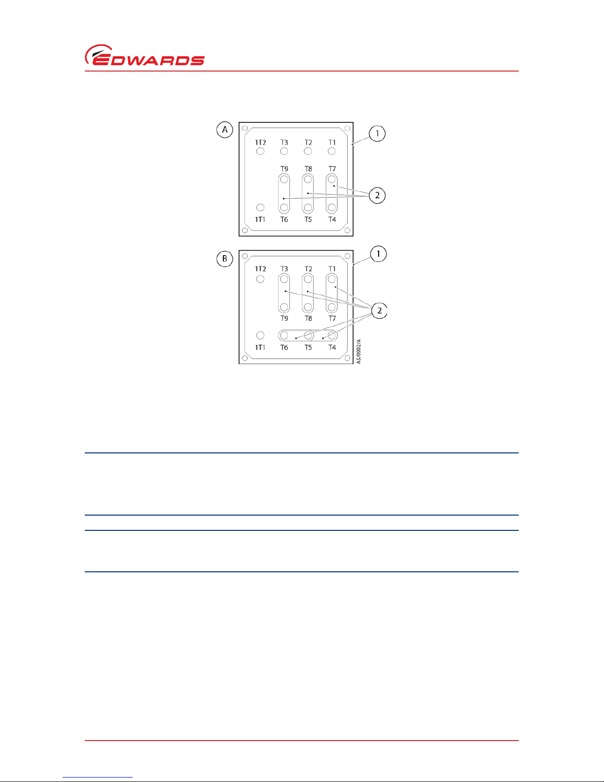
3.8.2 Reconfigure the iH system for your electrical supply (iH80/600 only)
If you want to use an iH80 or iH600 system with a different electrical supply, use the following procedure:
1. Refer to Figure 10. Undo and remove the six screws which secure the rear cover over the HCDP pump-motor, and
remove the rear cover.
2. Undo and remove the four screws which secure the cover to the pump-motor terminal-box.
3. Look at the links in the terminal-box (1):
z For high voltage operations (380-415 V at 50 Hz or 460 V at 60 Hz), ensure that the links (2) are in the
positions shown in Figure 10.
z For low voltage operations (200-208 V at 50 Hz or 200-230 V at 60 Hz), ensure that the links (2) are in the
positions shown in Figure 10.
4. Refit the cover to the pump-motor terminal-box and secure with four screws.
5. Refit the rear cover and secure with the six screws.
6. If you have iH600, continue at Step 7, otherwise continue at Section 3.8.3.
7. Undo and remove the four screws, which secure the electrics box to the rear of the iH system, then carefully
lower and support the module. Ensure that you do not disconnect, break or damage any of the cables connected
to the module.
8. Carry out steps 2, 3 and 4.
Refit the electrics box to the rear of the iH system and secure with the four screws: ensure that you do not trap any
of the cables connected to the electrics box.
Page 26

A590-00-880 Issue D
Page 20 © Edwards Limited 2008. All rights reserved.
Edwards and the Edwards logo are trademarks of Edwards Limited.
Installation
Figure 9 - Reconfigure the iH system for your electrical supply
1. Cover
2. Screw (2 off)
3. Electrics box
4. Common cable
5. Voltage select cable
6. Terminal block
Page 27
© Edwards Limited 2008. All rights reserved. Page 21
Edwards and the Edwards logo are trademarks of Edwards Limited.
Installation
A590-00-880 Issue D
Figure 10 - Reconfigure the pump-motor terminal-boxes (iH80/iH600 only)
3.8.3 Connect the electrical supply
CAUTION
This is an industrial (Class A) product as defined by EN61326. To ensure compliance with European
Electromagnetic Compatibility (EMC) requirements for EMC emissions, please note that it is not intended for use
in domestic buildings, or in properties directly connected to an electrical supply network which also supplies
domestic buildings.
CAUTION
Do not connect voltages greater than specified in Table 5 to the control/interface connections. If you do, the
interface control may be damaged.
Notes: 1. Edwards recommend that the electrical supply be connected to a suitable isolator, which is easily
accessible for maintenance and clearly identified.
2. If you need further information on connecting the electrical supply, look it up on the Web using URL at
the start of manual, or contact your supplier or Edwards for advice.
1. Pump-motor terminal-box
2. Links
Page 28

A590-00-880 Issue D
Page 22 © Edwards Limited 2008. All rights reserved.
Edwards and the Edwards logo are trademarks of Edwards Limited.
Installation
3. On an iH160,1000 or 1800 system, the earth (ground) installation must ensure that there is an
equipotential zone around the iH system: the voltage between the protective earth (ground) stud on the
iH system and any other conducting surface within 2 metres of the iH system must be <30 V r.m.s.
4. If you connect the electrical supply to an iH160,1000 or 1800 system through ELCB relays, they must be
suitable for protection of equipment with a d.c. component in the fault current, and suitable for short
duration switch-on surges, and for high leakage current (for example, type B, according to prEN50178).
The iH160,1000 or 1800 system is for use only with equipment that has no accessible terminals.
Refer to Figure 4, item 9.
Use the following procedure to connect the electrical supply to the iH system. When you make your electrical supply
cable, ensure that the earth (ground) conductor is longer than the phase conductors. This will ensure that if the cable
is accidentally dragged and the strain relief bush on the electrical supply connector mating-half fails, the earth
(ground) conductor will be the last conductor to be pulled from the connector.
1. Refer to Figure 11. Remove the connector block from the cover (10) of the mating-half supplied for the
electrical supply connector, then pass a suitable cable (9) through the strain relief bush (8) on the cover (10).
Refer to Section 2 for suitable cable sizes.
2. Connect the cable phase wires to the pins in the connector block as shown in Ta bl e 5 .
3. Connect the earth (ground) wire of the cable to one of the two earth (ground) screws (7) on the side of the
connector block.
4. Refit the cover (10) to the connector block then tighten the strain relief bush (8).
5. Fit the mating-half to the electrical supply connector (2) on the Electrics Box (1).
6. Connect the other end of the electrical supply cable to your electrical supply through a suitable isolator, or via
the disconnect box (refer to Section 7.3).
7. On iH80, 160 and 600 systems, we recommend that you fit a second protective earth (ground) conductor to the
protective earth (ground) stud on the Electrics Box (Figure 3, item 1) and connect the other end of this
conductor to your factory earth (ground). On an iH1000 and 1800 systems, you must
fit a second protective earth
(ground) conductor.
Page 29

© Edwards Limited 2008. All rights reserved. Page 23
Edwards and the Edwards logo are trademarks of Edwards Limited.
Installation
A590-00-880 Issue D
Figure 11 - Connect the electrical supply cable to the connector mating-half
3.9 Connect an additional RF earth (ground) (optional)
If you will operate the iH system in an area subject to high RF (radio frequency) emissions, in accordance with good
RF installation practice, we recommend that you:
z Use a star washer to connect the end of the earth (ground) cable (Figure 5, item 4) connected to the iH inlet
to one of the bolts that you use to secure the inlet-flange.
z Connect an additional earth (ground) cable to the RF earth (ground) stud (Figure 3, item 5). You must use a
suitable low-impedance cable (for example, use braided cable).
3.10 Connect to your emergency stop circuit
Note: If you do not connect to your own control equipment, you must fit the Tool Interface Module plug supplied
(Figure 4, item 7) on the rear of the iH system. If you do not, you will not be able to operate the iH system.
If required, you can connect your own control equipment to the iH system to shut it down in an emergency using the
EMS connection (Figure 4, item 7 and Table 5). The emergency stop control must be compliant with IEC 60947-5-1
(This should be a red self latching mushroom push button on a yellow background.).
1. Electrics box
2. Electrical supply connector
3. Electrics box
4. Pin 1 (phase 1)
5. Pin 2 (phase 2)
6. Pin 3 (phase 3)
7. Earth (ground) screw
8. Strain relief bush
9. Electrical supply cable
10. Cover
Page 30

A590-00-880 Issue D
Page 24 © Edwards Limited 2008. All rights reserved.
Edwards and the Edwards logo are trademarks of Edwards Limited.
Installation
3.11 Connect the cooling-water hoses
Notes: 1. For optimum water-cooling, ensure that your cooling-water supply complies with the data given in
Table 1 and that they are connected in parallel. Refer to Figure 3, items 3 and 6. Edwards would
recommend that quick connectors be used to reduce the risk of water spillage during connection/
disconnection.
2. For minimum water consumption, regulate the cooling-water flow to the iH system.
Connect the cooling-water supply as follows:
1. Use 3/8 inch BSP male pipe fittings (which you must supply) to fit the female quick-release connector to the
cooling-water supply hose and to fit the male quick-release connector to the cooling-water return hose.
2. Remove the dust-caps from the cooling-water inlet and outlet.
3. Connect your water return hose to the cooling-water outlet (Figure 3, item 6) and connect your water supply
hose to the cooling-water inlet (Figure 3, item 3).
4. Turn on the cooling-water supply.
5. Inspect the water hoses, pipelines and connections and check that there are no leaks.
Turn off the water supply while you complete the remainder of the installation procedures.
3.12 Accessories
Refer to the individual accessories manuals for installation, information, refer to Section 7.3.
The disconnect box when fitted, is used to energize and isolate the power supply to the system. It also allows the
isolation of the electrical supply during an emergency, and for maintenance and trouble shooting the system, thereby
satisfying SEMI S2 requirements. The photohelic switch/gauge when fitted, allows monitoring for loss of extraction
from the enclosure, thereby satisfying SEMI S2 requirements.Refer to the individual accessories manuals for
information about installation.
WARNING
Do not leave the cooling-water supply turned on until after you complete the electrical installation
of the pump. If you do, condensation may form inside the enclosure and there may be a risk of
electric shock.
Page 31

© Edwards Limited 2008. All rights reserved. Page 25
Edwards and the Edwards logo are trademarks of Edwards Limited.
Installation
A590-00-880 Issue D
3.13 Commission the system
1. Switch on the external electrical supply and check that the power OK LED (Figure 6, item 3) goes on. If the LED
does not go on, contact Edwards or refer to the Web.
2. Switch on the cooling-water and nitrogen supplies.
3. Ensure that the exhaust-extraction system is not blocked (for example, that valves in the exhaust-extraction
system are open).
4. Ensure that all openings to atmospheric pressure in the foreline vacuum system are closed.
5. Connect the PDT to the front of the iH system (Figure 6, item 4).
6. Press CONTROL button, press ENTER button, LOCAL CONTROL green LED illuminates, press START, press ENTER.
7. If the iH system starts and continues to operate, continue at Step 8. If a warning or alarm condition is indicated:
z Shut-down the iH system: refer to Section 4.3.
z Contact Edwards or refer to the Web.
8. Look at the pressure gauge in your inlet pipeline:
z If the pressure is increasing, the HCDP pump-motor terminal-box (and/or if you have an iH160, 1000 or 1800
system, the HMB pump-motor terminal-box) is incorrectly wired: immediately shut down the iH system,
correct the electrical wiring, then repeat this procedure from step three again.
z If the pressure is decreasing continue at Step 9.
9. After you have commissioned the iH system:
z If you want to continue to operate the iH system, refer to Section 4.1, Step 4.
z Otherwise, shut-down the system: refer to Section 4.3.
WARNING
During some application cycles it is possible that the system may exceed OSHA 1910.95
Occupational Noise Exposure Limits, the EU noise directive
2003/10/EC or other regional noise limits dependant upon the process, duty cycle, installation or
environment in which being operated. A sound pressure survey must be conducted after
installation and, if necessary, controls implemented to ensure that the relevant limits are not
exceeded during operation and that adequate precautions are taken to prevent personnel from
exposure to high noise levels during operation.
Page 32

A590-00-880 Issue D
Page 26 © Edwards Limited 2008. All rights reserved.
Edwards and the Edwards logo are trademarks of Edwards Limited.
Installation
3.14 Install additional safety equipment
If the sensors or microprocessors fail, the total flow rate of nitrogen displayed or output by the iH system may be
incorrect. If you need to know the total flow rate of nitrogen to the dry pump for safety reasons, you should therefore
fit suitable measurement equipment in the nitrogen supply pipeline. If you fit a rotameter, ensure that it is suitable
for use with nitrogen and that it is correctly calibrated.
If the nitrogen supply to the iH system fails, a warning message will be shown on the Pump Display Terminal (if fitted)
and will be sent to the Interface Module(s) connected to the iH system. Ensure that your installation is configured so
that it remains safe if there is a failure of the nitrogen supply to the iH system.
If an alarm condition is detected (and the iH system is not configured to 'run til crash' refer to Section 4.4) the iH
system will shutdown automatically. You must ensure that your ins ta llation remains safe if the iH system shuts down
automatically.
WARNING
If your Process Tool/control system needs to know the total flow rate of nitrogen to the system for
safety reasons, install suitable measurement equipment in the nitrogen supply pipeline.
WARNING
If you use the nitrogen purges to dilute dangerous gases to a safe level, ensure that the system
shuts down if the nitrogen supply to the system fails.
Page 33
© Edwards Limited 2008. All rights reserved. Page 27
Edwards and the Edwards logo are trademarks of Edwards Limited.
Operation
A590-00-880 Issue D
4 Operation
4.1 Start-up
CAUTION
The system is designed to ride through short term power interruption and to automatically restart once the
power is restored.
CAUTION
Do not operate the pump if the pipeline is restricted or blocked as the pump will not operate correctly and may
be damaged.
Refer to Section 1.1 and 3.6.
1. Switch on the cooling-water and nitrogen supply.
2. Switch on the electrical supply.
3. Check that the exhaust-extraction system is not restricted, and that any valves in the exhaust-extraction system
are open.
The pump can be started using either the iTIM, the PDT or the IM.
iTIM and IM operation:
4. Use your control equipment to set the pump start/stop signal to the interface connector and check that the
Running LED is illuminated.
z Control must be taken with the iTIM. The message 'iTIM IN CONTROL' will be displayed on the PDT if
connected.
WARNING
Do not operate the system with any enclosure panels removed or damaged and do not touch any
parts of the pump(s) when the system is on. Surfaces of the pump(s) are very hot and can cause
injury to people.
WARNING
Do not operate the system with any enclosures removed or damaged. If you do there may be a risk
of an electric shock.
WARNING
Ensure that it is safe to start the system. If you do not (and, for example, maintenance is being
performed on components downstream of the system), you could cause injury to people.
WARNING
After the power is applied, the contactors will pull in automatically and all mains circuits will be
energised.
Page 34
A590-00-880 Issue D
Page 28 © Edwards Limited 2008. All rights reserved.
Edwards and the Edwards logo are trademarks of Edwards Limited.
Operation
PDT operation:
5. If the system is to be operated using the PDT.
z Connect the PDT to the required PDT connection, front (Figure 6, item 4).
z Press CONTROL button, press ENTER button, LOCAL CONTROL green LED illuminates.
z Press START button.
z Press ENTER.
z The system will start and the Running LEDs will be illuminated.
4.2 Status indicators
Refer to Figure 6.
4.3 Manual shut-down
The pump can be shutdown using either the iTIM, the PDT or the IM. Note that only the item in control can stop the
pump (refer to Section 1.4).
iTIM and IM operation:
1. Use your control equipment to reset the pump start/stop signal to the interface connector. The Running LED
(Figure 6, item 2) will then go off, and the pump running status output signal will open.
PDT operation:
CAUTION
If you stop the pump without the nitrogen purge cycle i.e. using the EMS button, on processes that have
condensable or solid by-products then the pump may not restart.
1. Use the PDT to select Auto or Fast shut-down mode, both introduce nitrogen purge cycle.
If the pump is not going to be required for some time, switch off the electrical supply and the cooling-water supply.
WARNING
If you shut the system down and don’t isolate it from the electrical supply, do not disconnect the
Pump Display Terminal or release control from the Pump Display Terminal or front panel. If you do
the system could be started by another Module.
WARNING
Do not remove the inlet connections until the pump has been allowed to stop rotating and the
power has been isolated. The pump can take up to three minutes to completely stop.
Page 35

© Edwards Limited 2008. All rights reserved. Page 29
Edwards and the Edwards logo are trademarks of Edwards Limited.
Operation
A590-00-880 Issue D
4.4 Automatic shut-down
CAUTION
If you select 'Run 'til crash', the pump(s) can be damaged and you may invalidate any warranties on the iH system
equipment.
Normally, if an alarm condition exists, the iH control system will shutdown the iH system. If required you can request
'run 'til crash' operation. In this mode of operation, most alarm conditions will be ignored and the pump(s) will
continue to operate. For safety reasons the following alarms will shut-down the iH system even if you have selected
'run til crash':
Note: 'Run 'til crash' is automatically reset to 'off' when the electrical supply is removed.
z HCDP CURRENT HIGH/LOW (error numbers 310 and 312).
z HCDP THERMISTOR HIGH (error number 512).
z EXHAUST PRESSURE (error number 3912).
On an iH160, 1000 or 1800 system, the following alarms will cause only the HMB pump to shut down, provided 'run til
crash' is not selected:
z HMB POWER HIGH/LOW (error numbers 810 and 812).
z HMB PHASE IMBALANCE (error number 1012).
On an iH160, 1000 or 1800 system, the following alarms will cause only the HMB pump to shut down, whether 'run til
crash' is selected or not:
z HMB CURRENT HIGH LOW (error numbers 710 and 712).
HMB THERMISTOR HIGH (error number 912).
4.5 Unplanned shutdown and alarms
The iH system is fitted with a number of pump protection sensors (refer to Table 7) that will give warnings and
alarms. The decision on whether or not to shutdown the pump is left with the tool.
If the iH system has an unplanned shutdown, ensure that the cause of the shutdown is identified and rectified before
restarting. If you are in any doubt, please call a Edwards Service Engineer.
Tab l e 7 - Sa f ety s en sor s
Safety sensor Shut-down condition
HCDP pump-motor thermistor When the thermistor in the HCDP pump-motor indicates that the temperature
of the pump-motor is nominally 150 °C.
HMB pump-motor thermistor
*
*
iH600/1000/1800 systems only.
When the thermistor in the HMB pump-motor indicates that the temperature
of the pump-motor is nominally 150 °C.
Exhaust pressure transducer
†
†
Accessory.
When the pressure in the exhaust pipeline is 9 psig or higher.
Photohelic switch When the extraction from the exhaust enclosure is lost.
Page 36

A590-00-880 Issue D
Page 30 © Edwards Limited 2008. All rights reserved.
Edwards and the Edwards logo are trademarks of Edwards Limited.
Operation
4.6 Emergency stop
Note: The emergency stop switch is not an electrical isolator.
Note: The use of emergency stop will not automatically shut down the load lock pump (if fitted); you must shut
down the load lock pump separately.
To shut down the iH system in an emergency, press the emergency stop switch (Figure 6, item 1). Alternatively, you
can operate the emergency stop controls in your own control system if you have connected your emergency stop
circuit to the iH system as described in Section 3.10.
When emergency stop is selected:
z The pump (and the booster pump) is switched off.
z The solenoid-valve(s) in the Gas Module close, to switch off the supply of nitrogen to the pump.
z The solenoid-valve(s) in the temperature control manifold(s) de-energise with loss of temperature control.
z The Pump Display Terminal will display 'STOP ACTIVATED'. (If connected)
z The Running LED will go off.
z The Alarm LED illuminates.
4.7 Restart the pump after an emergency stop or automatic shut-
down
Note: If the iH system has automatically shut down because of high pump power, check that the pump is free to
rotate before you restart the iH system: refer to the Web.
If you have used the emergency stop switch on the front panel to shut down the iH system, you must reset the
emergency stop switch before you can restart the iH system. Turn the emergency stop switch to reset it, then restart
the iH system as described in Section 4.1.
If the iH system has been automatically shut down because of an alarm condition, the alarm condition must be
rectified before you can restart the iH system. Restart the iH system as described in Section 4.1.
4.8 Single equipment monitor (SEM)
CAUTION
Ensure that you use the correct configuration setpoints for your application. If you do not, the iH system may
be damaged during operation.
If there is an SEM connected to your iH system, you are able to download configuration sets, which contain preset
configuration values, for example setpoints. Contact Edwards or go to the Web for more details.
Page 37

© Edwards Limited 2008. All rights reserved. Page 31
Edwards and the Edwards logo are trademarks of Edwards Limited.
Maintenance
A590-00-880 Issue D
5Maintenance
5.1 Safety and maintenance frequency
z Ensure that the maintenance technician is familiar with the safety procedures which relate to the products
pumped.
z Allow the pumps to cool to a safe temperature before you fit lifting bolts or start maintenance work.
z Vent and purge the dry pumping system with nitrogen before you start any maintenance work.
z Isolate the dry pumping system and other components in the process system from the electrical supply so
that they cannot be operated accidentally. Note that the emergency stop switch on the dry pumping system
is not an electrical isolator, unless a disconnect box accessory is installed.
z Wait for at least four minutes after you have switched off the electrical supply before you touch any
electrical component on the dry pumping system.
WARNING
Only personnel specially trained to perform electrical maintenance should attempt
troubleshooting inside electrical enclosures. These enclosures contain hazardous voltages and are
not operator areas.
WARNING
Leak test the system after maintenance and seal any leaks found to prevent leakage of dangerous
substances out of the system and leakage of air into the system.
WARNING
Obey the safety instructions given below and take the appropriate precautions. If you do not, you
can cause injury to people and damage to equipment.
WARNING
Electrical, nitrogen and water supplies are all potentially hazardous energy sources. Before
carrying out any maintenance the supply of these sources should be locked and tagged out.
WARNING
The iH1800HTX has two separate power supplies, one for the pump system and the other for the
exhaust TMS.
WARNING
Personal protection equipment should be checked and used as specified by its supplier. Hazardous
chemicals that have been pumped are located within the pumps and piping. Use of suitable
protective gloves and clothing along with a respirator is recommended if contact with substances
is anticipated.
Particular caution should be exercised when working with hydrocarbons which may have been
exposed to temperatures greater than 260 °C. Refer to Edwards Material Safety Data Sheets for
detailed information.
Page 38

A590-00-880 Issue D
Page 32 © Edwards Limited 2008. All rights reserved.
Edwards and the Edwards logo are trademarks of Edwards Limited.
Maintenance
z Route and secure cables, hoses and pipelines during maintenance to avoid possible risk of trips or
entrapment.
z Ensure that any oil or water collected in the secondary containment drip tray is removed before moving the
system.
z The enclosure panels should only be removed with the use of a special tool, when the system has been
switched off and allowed to cool sufficiently (as an indication the system should be left for one hour with
cooling water still connected at 1 l min
-1
).
z Wear the appropriate safety-clothing when you come into contact with contaminated components. Dismantle
and clean contaminated components inside a fume-cupboard.
z Re-check the pump rotation direction if the electrical supply has been disconnected.
z O-ring replacement intervals vary depending on your application.
z Dispose of components, grease and oil safely.
z Take care to protect sealing-faces from damage.
Do not touch or inhale the thermal breakdown products of fluorinated materials which may be present if the iH
system has been overheated to 260 °C and above. These breakdown products are very dangerous. Fluorinated
materials in the iH system may include oils, greases and seals. The iH system may have overheated if it was misused,
if it malfunctioned or if it was in a fire. Edwards Material Safety Data Sheets for fluorinated materials used in the
pump are available on request: contact your supplier or Edwards. (refer to the address page at the rear of this manual
for contact details).
The iH system requires little user maintenance. Safety sensors fitted to the iH system do not require routine
maintenance. The maintenance operations you can carry out are described in the following sections, any other
maintenance must be carried out by Edwards service centres (refer to Section 7). The frequency of maintenance
operations depends on your process. Adjust the frequency of maintenance operations according to your experience.
When you maintain the iH system, use Edwards maintenance and service kits. These contain all of the necessary seals
and other components necessary to complete maintenance operations successfully. Ensure that your nitrogen and
cooling-water supplies comply with the data given in Section 2 and that they are connected in parallel. Contact
Edwards or refer to the Web.
5.2 Relocate the system for maintenance
WARNING
The substances that accumulate in the exhaust-pipe, elbow and check-valve can be dangerous. Do
not allow these substances to come into contact with your skin or eyes. Do not inhale vapours from
these substances. Fit blanking caps to the inlet and outlet flanges when you move the exhaustpipe, elbow or check-valve around your workplace.
The majority of synthetic oils/grease can cause inflammation of the skin (dermatitis). Safety
precautions must be taken to prevent prolonged skin contact with these substances. Use of
suitable protective gloves and clothing along with a respirator is recommended if contact with the
substance is anticipated.
System process gases and residue can be highly toxic. Take all necessary precautions when
handling components that have, or could have, come into contact with them, including O-rings,
lubricants and all exhaust accessories.
WARNING
You must use suitable lifting equipment to move the system. It is too heavy to lift by hand.
Page 39

© Edwards Limited 2008. All rights reserved. Page 33
Edwards and the Edwards logo are trademarks of Edwards Limited.
Maintenance
A590-00-880 Issue D
CAUTION
Drain the cooling-water from the iH system, if you will transport or store it in conditions where the cooling-water
could freeze. If you do not, cooling-water may freeze in the iH system and damage the pump(s) and/or the
cooling-water pipelines.
If you want to remove the iH system from its operating location and move it to another location where you will do
maintenance, use the following procedure:
1. Purge the iH system and shut down the iH system as described in Section 4 and allow the iH system to cool down.
2. Isolate the power by disconnecting the mating-half from the electrical supply connector, then isolate the water
and the gas purge supply.
3. Switch off your nitrogen and cooling water supplies. Disconnect the nitrogen supply, taking care as any trapped
gas under pressure is released. Disconnect the cooling-water supply followed by the cooling-water return.
4. Disconnect the inlet and outlet from the vacuum and exhaust systems and fit blanking caps.
5. If necessary, disconnect the iH air-extraction port from your factory extraction system.
6. If necessary disconnect any accessories from the iH system.
7. Adjust the levelling feet so that the iH system rests on the castors.
8. Move the iH system to the location where you will do maintenance.
After maintenance is complete, re-install the iH system as described in Section 3.
5.3 Cleaning the pump
CAUTION
Do not use cleaning materials based on strong alkalis, aggressive or chlorinated solvents. Do not use cleaning
materials containing abrasives.
Inspect the pump monthly and, if necessary, wipe the outside clean with a soft lint free cloth and a proprietary
cleaning material based on demineralised water or isopropanol.
5.4 General maintenance
The following maintenance can be carried out on the system, refer to Web and/or contact Edwards for details and
training:
z Check purge gas flow rates
z Inspect and clean exhaust pipe, elbow, and check valve
z Check oil levels
z Change oil
z Check TMS operation.
WARNING
Do not exceed the topple angle of 10° when moving the pump. Wheel the system on its castors to
move it into its operating position. The system should only be wheeled short distances over flat
surfaces. If the floor surface is uneven or has obstacles the system should be lifted with suitable
lifting equipment.
Page 40

A590-00-880 Issue D
Page 34 © Edwards Limited 2008. All rights reserved.
Edwards and the Edwards logo are trademarks of Edwards Limited.
Maintenance
5.5 Replace a fuse
You can only change the low voltage fuses F8 to F10 (Figure 4, items 3 to 5) for the d.c. electrical supply, the iM
interface and communications module and the emergency stop circuit. Only change a fuse if you have identified and
rectified the cause of the failure.
To change a fuse, refer to Figure 4 and use the following procedure. If the fuse immediately fails when you replace
it, there may be an electrical fault: contact your supplier or Edwards for advice.
1. Use a flat-bladed screwdriver to undo the fuse holder (items 3 to 5) by a 1/4 of a turn, then remove the fuse
holder from the Electrics Box.
2. Remove the failed fuse from the fuse holder.
3. Fit a new fuse of the correct rating in the fuse holder. Refer to Ta b l e 6 for the fuse ratings.
Refit the fuse holder in the Electrics Box, then use a flat-bladed screwdriver to turn the fuse holder clockwise by a
1/4 of a turn to secure it in place.
5.6 Inspect the connections, pipelines, cables and fittings
1. Remove the enclosure side and top panels.
2. Check that all the connections are secure; tighten any loose connections. Inspect all cables, pipelines, hoses and
connections and check that they are not corroded or damaged and do not leak; repair or replace any pipelines,
hoses and connections that are corroded or damaged, or which leak.
Refit the enclosure side and top panels.
WARNING
Ensure that you replace a fuse with a new fuse of the correct rating. If you do not, the system will
not be adequately protected and you can damage the system or cause injury to people. Do not
remove the cover from the electrics box. High voltages exist in the electrics box when it is
connected to the electrical supply. There are no spare parts that can be serviced in the electrics
box.
Page 41

© Edwards Limited 2008. All rights reserved. Page 35
Edwards and the Edwards logo are trademarks of Edwards Limited.
Transportation, storage and disposal
A590-00-880 Issue D
6 Transportation, storage and disposal
6.1 Transportation
Follow the procedure laid out in Section 6.2 and then read form HS1 and fill out form HS2, which can be found at the
back of this manual.
6.2 Storage
CAUTION
Drain the cooling-water from the iH system, if you will transport or store it in conditions where the cooling-water
could freeze. If you do not, the cooling-water may freeze in the iH system and damage the pump(s) and/or the
cooling-water pipelines.
Store the iH system as follows:
1. Follow the procedure set out in Section 5.2.
2. Store the iH system in clean dry conditions until required.
3. When required for use, prepare and install the iH system as described in Section 3 of this manual.
6.3 Disposal
Edwards products are supported by a world-wide network of Edwards Service Centres. Each Service Centre offers a
wide range of options including disposal. Refer to Section 7.2 for more information.
Pump system materials suitable for recycling include cast iron, steel, SG iron, PTFE, stainless steel, brass, aluminium,
zinc alloy, nickel, mild steel, ABS.
Take particular care with the following:
z Fluoroelastomers which may have decomposed as the result of being subjected to high temperatures.
z Components which have been contaminated with dangerous process substances.
WARNING
Do not drain the oil from the pump(s) whether dangerous substances have been pumped or not.
You must fit blanking plates to seal all vacuum inlet and outlet ports (to prevent possible oil
leakage). You must ensure that the system is correctly labelled, if in doubt contact Edwards.
WARNING
Dispose of the system and any components safely and in accordance with all local and national
safety and environmental requirements.
Page 42

A590-00-880 Issue D
Page 36 © Edwards Limited 2008. All rights reserved.
Edwards and the Edwards logo are trademarks of Edwards Limited.
This page has been intentionally left blank.
Page 43
© Edwards Limited 2008. All rights reserved. Page 37
Edwards and the Edwards logo are trademarks of Edwards Limited.
Service, spares and accessories
A590-00-880 Issue D
7 Service, spares and accessories
7.1 Introduction
Notes: 1. Whenever you return the iH system to a Edwards Service Centre or other Edwards company, you must
comply with the requirements of Section 6 and with the requirements of the Return of Edwards
Equipment Procedure (refer to forms HS1 and HS2 at the end of Important Safety Information).
2. You must not drain the oil from the iH pump. You must clearly state the pump is full of oil when you
complete form HS2.
Edwards products, spares and accessories are available from Edwards companies in Belgium, Brazil, Canada, China,
France, Germany, Israel, Italy, Japan, Korea, Singapore, Switzerland, United Kingdom, U.S.A and a world-wide
network of distributors. The majority of these centres employ Service Engineers who have undergone comprehensive
Edwards training courses.
Order spare parts and accessories from your nearest Edwards company or distributor. When you order, please state
for each part required:
z Model and Item Number of your equipment
z Serial number (if any)
z Item Number and description of the part.
7.2 Service
Edwards products are supported by a world-wide network of Edwards Service Centres. Each Service Centre offers a
wide range of options including: equipment decontamination; service exchange; repair; rebuild and testing to factory
specifications.
Equipment that has been serviced, repaired or rebuilt is returned with a full warranty. Your local Service Centre can
also provide Edwards engineers to support on-site maintenance, service or repair of your equipment.
For more information about service options, contact your nearest Service Centre or other Edwards company.
7.3 Ordering accessories
WARNING
Whenever you return the dry pumping system to a Edwards Service Centre or other Edwards
company, you must comply with the requirements of Section 6 and with the requirements of the
Return of Edwards Equipment Procedure (refer to forms HS1 and HS2 at the rear of this manual).
Table 8 - Accessories
Accessory Item Number
Pump display terminal 5-way XLR plug (PDT) D372-80-700
PDT extension cables XLR 5 way
3 m D373-70-591
5 m D373-70-592
10 m D373-70-595
15 m D373-70-596
25 m D373-70-597
Page 44

A590-00-880 Issue D
Page 38 © Edwards Limited 2008. All rights reserved.
Edwards and the Edwards logo are trademarks of Edwards Limited.
Service, spares and accessories
Exhaust temperature sensor A532-07-000
Active gauge connection kit D372-41-000
iTIM
E73+A1+T1 D374-20-000
E73+A1+T1 serial D374-21-000
MCM+L1 D374-22-000
MCM+L1 serial D374-23-000
PC interface kits
Desktop D372-18-100
Laptop (USA) D372-18-200
Laptop (Europe) D372-18-300
Laptop (UK) D372-18-400
Laptop (Japan) D372-18-500
PCMCIA Laptop D372-17-000
Nitrogen flow switch A532-54-000
IH Disconnect box U20000445
IH Photohelic switch / gauge kit U30004021
Heated exhaust purge kit (HTX variants) A533-24-015
TMS control unit (HXT variants)
230 V, 50 Hz, single phase Y142-01-000
208 V, 60 Hz, 3-phase Y142-02-000
200V, 50/60 Hz, 3-phase Y142-03-000
IH80, 600, and 1000 Enclosure extraction fan kit A505-39-000
PDT Holster D372-09-800
PDT Adaptor, 5-way XLR plug/RJ12 socket D373-70-526
Table 8 - Accessories (continued)
Accessory Item Number
 Loading...