

Page 1

Instruction Manual
EXTPX Split Flow
B760-60-880
Issue A Original
Description Item Number
24 Volt EXT400/200PX Split flow compound Turbomolecular Vacuum Pump B760-61-991
24 Volt EXT400/200PX Split flow compound Turbomolecular Vacuum Pump B760-62-991
24 Volt EXT400/200/30iPX Split flow compound Interstage Turbomolecular Vacuum Pump B760-67-991
24 Volt EXT400/200/30iPX Split flow compound Cartridge Interstage Turbomolecular Vacuum Pump B760-53-991
Page 2

@o*,"Fttrt=.
Declaration
We, Edwards,
l"lanor
Royal,
Crawtey,
West Sussex RH10 9LW, UK
declare under our sote responsibility
DffPX Compound Turbomotecutar
Dfi40020030iPX cartridge interstage 8760-53-991'
Dfi400200PX
ECT400200PX
Dff40020030iPX short chamber + end
to which
normative
this dectardtion retates is in conformity with the fottowing standard(s) or other
document(s)
EN(|5O)12100-2: 2003 Safety of l,lachinery - B6ic Concepts, Generat Principtes for Design.
EN1012-2t 1997 Compr6sors and Vacuum
EN610'l0-1: 2001t Safety
EN6t326: 1997 Eectrical equipment for measurement, control and laboratory use
(immunity,
Cla5s B Emissions)
C22.2 No 61010.1-04F
UL6101O-1
'
pumps
The
manuat supplied
"
24V Pumps onty compty with the Canadian Standard Authority and UnderwriteB laboratory
when used with D(DC 24V famitv of controtlers.
'optiport'
'optiport'
(2'd
Edition;# safety requirements for etectricat equipment for medurement,
compty with EN61010-1 when instatled in accordance with the instruction
+
Technicat Principats,
laboratory use.
E IC requirements,
Safety requirements for
Controt and taboratory use, Part 1: General requirements
Controt ard taboratory use, Part 1!
with
the
that the
port
end
requirements for
pump.
of Conformity
product(s)
pump:
8760-61-991
8760-62-991
oott 8760-67-991
pumps,
etectricat equipment
electricat
Safety Requirements. Vacuum Pumps.
equipment ior measurement,
Generat
for meaiurement controt and
requirements
following the
2006t95tEC
2@4t't08tEc
98tX7tEC
provisions
of
Vottage Directive.
Low
ElectrorEgnetic
^,lachirErv Directive
e.ca----t^',
B, D, Brewster,
&)rge5s Hill
Technical hlanager
PrducE
product
This
has been manufactured
Compatibitity Directive
zL?t<^
9,)d,a\e59
Date and Place
quality
under a
system
O.l€
registered to |SO9W1
>',r
a
t
Lr.-
Z'cxlr
c
-
s
Page 3

l?nwa,FrD=
Declaration
We,
Edwards,
Manor Royat,
Crdwtey,
West Sussex RH10 9LW, UK
declare under our sote rGponsibitity that the madfne(s)
Description
EXT40020030iPX Cartridge inGrstage
to which this dectaration relates is intended to be incorporated into other equipment and not
function independentty. The machine(s) is in conformity with the fottowing standard(s)
normative
document(5)
(l5O)12100-2:
EN
EN1012-2: 1997 Compressors and Vacuum
EN61010-l: 2001.
EN61326: 1997
(immunity,
2003 Safety of Machinery - Basic Concepts, General Principtes for
Design. Technicat Principals.
PumDs.
Safety requirements for electrical equipment for measurement
control and laboratory use.
EtectricaI equipment for measurement, control and [abordtory use
EMC requi rements.
of Incorporation
Item number
8760-53-991
or other
pumps.
safety Requirements. Vacuum
Ctass B Emissions)
C22.2 No 61010.1-04 Safety requirements for electrical equipment for measurement,
Ut6101o-1
*
The
manual supptied with the
'
24V Pumps onty compty with the Canadian Standard Authority and
when used
(2"d
Edition)' safety requirements for etectricat equipment for measurement,
pumps
compty with EN61010-1 when instatled in accordance
with
Controt and laboratory
Controt and laboratory
pump.
24V famity of controtleB.
ExDc
use, Part 1: General requirements
use, Part
General requirements
1:
with tJle instruction
underwriteE Labontory
to
The machine(s) must not be
has been brought into
conformity with the fottowing
2006t95tEC
20ut108tEc
98t17 tEC
Brewster, Technlcat Manager
B. D.
Burgess Hitt Product5
This
product
has been monufoctured
put
Lo
Etectromagnetic
service untit the equipment into
into
,
Vottage Directive.
compatibitity Directive
Machinery Directive
under o
provisions
2-t++.'_
Go
quality
|y6tem
which
it is incorporated
<)
c-xG!=-,,- 2-c,-?
rz<<ZS9 At
Dak ahd Place
registered to lSOgNl
rL-
Page 4

This page has been intentionally left blank.
Page 5

B760-60-880 Issue A
Contents
Section Page
1 Introduction .......................................................................................1
1.1 Scope and definitions ................................................................................................... 1
2 Technical data ....................................................................................3
2.1 General .................................................................................................................... 3
2.2 Pumping media ........................................................................................................... 5
2.3 Vent gas specification and vent control data ....................................................................... 7
2.4 Purge gas specification and data ...................................................................................... 7
2.5 Materials exposed to gases pumped .................................................................................. 7
3 Installation .................................................... ................................... 13
3.1 Unpack and inspect .....................................................................................................13
3.2 Typical installation .....................................................................................................14
3.3 Connection to the vacuum system ...................................................................................16
3.3.1 Mechanical fixing .......................................................................................................16
3.3.2 Inlet screens .............................................................................................................16
3.3.3 Inlet connection and pump orientation .............................................................................17
3.3.4 Backing-port connection ...............................................................................................20
3.3.5 Booster port connection ...............................................................................................20
3.4 Vent options, vent-valve connection and control .................................................................20
3.5 Purge gas connection ...................................................................................................21
3.6 Electrical installation ..................................................................................................21
3.6.1 EXDC drive module .....................................................................................................22
3.6.2 TIC controller ............................................................................................................22
3.7 Cooling ...................................................................................................................22
3.7.1 Introduction .............................................................................................................22
3.7.2 Forced-air cooling ......................................................................................................22
3.7.3 Water-cooling ...........................................................................................................22
3.8 Magnetic fields ..........................................................................................................23
Contents
4 Operation ........................................................................................ 25
4.1 Start-up ..................................................................................................................25
4.2 Shut-down ................................................................................................................26
4.3 Safety interlocks and control system ................................................................................26
4.3.1 EXDC drive module .....................................................................................................26
4.3.2 TIC controller ............................................................................................................26
4.4 Bakeout ...................................................................................................................26
5 Maintenance ..................................................................................... 27
5.1 Introduction .............................................................................................................27
5.2 Bearing maintenance ...................................................................................................27
5.3 Rotor life .................................................................................................................27
5.4 Cleaning the pump ......................................................................................................27
5.5 Fault finding .............................................................................................................28
6 Storage and disposal ...... .... ..... ..... ..... ..... ..... ..... ................................... 31
6.1 Storage ...................................................................................................................31
6.2 Disposal ...................................................................................................................31
7 Service, spares and accessories .............................................................. 33
dcs/7784/01/08
© Edwards Limited 2007. All rights reserved. Page i
Edwards and the Edwards logo are trademarks of Edwards Limited.
Page 6

B760-60-880 Issue A
Contents
7.1 Introduction .............................................................................................................33
7.2 Service ....................................................................................................................33
7.3 Spares kits ...............................................................................................................33
7.3.1 Inlet screens .............................................................................................................33
7.3.2 Inlet strainer .............................................................................................................33
7.3.3 Inlet-flange seal .........................................................................................................33
7.4 Accessories ...............................................................................................................34
7.4.1 Installation ...............................................................................................................34
7.4.2 EXDC drive module .....................................................................................................34
7.4.3 TIC controller ............................................................................................................34
7.4.4 TAV vent-valve and vent port adaptor ..............................................................................34
7.4.5 VRX vent-restrictor .....................................................................................................35
7.4.6 PRX purge-restrictor ....................................................................................................35
7.4.7 ACX air-cooler ...........................................................................................................35
7.4.8 WCX water-cooler ......................................................................................................35
Index ................................................................ .............................. 37
For return of equipment, complete the HS Forms at the end of this manual.
Illustrations
Figure Page
1 Booster port performance with lines of constant backing pressure ............................................. 5
2 Dimensions of B76061991 EXT400/200PX split flow pump - large main and side ports (units in mm) ...... 8
3 Dimensions of B76062991 EXT400/200PX split flow pump -
large main and side ports plus end port (units in mm) ............................................................ 9
4 Dimensions of B76067991 EXT400/200/30iPX -
large side port and end port plus interstage port (units in mm) ................................................10
5 Dimensions of B76053991 EXT400/200/30iPX -
interstage cartridge pump with main, side ports plus interstage port (units in mm) ........................11
6 Schematic of a typical EXTPX split flow system ...................................................................15
7 Correct installation of inlet screen ..................................................................................17
8 Correct mounting attitude of the EXTPX split flow pump ........................................................19
9 Installation of optional accessories ..................................................................................36
Page ii © Edwards Limited 2007. All rights reserved.
Edwards and the Edwards logo are trademarks of Edwards Limited.
Page 7

B760-60-880 Issue A
Tables
Table Page
1 General data .............................................................................................................. 3
2 Technical data ........................................................................................................... 3
3 Vent gas and vent control data ........................................................................................ 7
4 Purge gas specification ................................................................................................. 7
5 List of items supplied ..................................................................................................13
6 Vent-restrictor orifice diameter (with atmospheric pressure at the inlet of the vent-valve) ..............21
7 Water-cooling block supply requirements ..........................................................................23
8 Fault finding .............................................................................................................28
9 Spares kits ...............................................................................................................33
10 EXDC drive module .....................................................................................................34
11 TIC controller ............................................................................................................34
12 TAV vent-valve and vent port adaptor ..............................................................................34
13 VRX vent restrictor .....................................................................................................35
14 PRX purge restrictor ....................................................................................................35
15 ACX air-cooler ...........................................................................................................35
16 WCX water-cooler ......................................................................................................35
Contents
Associated publications
Publication title Publication number
EXDC Turbomolecular pump drive module D396-45-880
TIC (100 W and 200 W) manual D397-22-880
TIC range CD D397-00-879
EXT pump accessories manual B580-65-880
© Edwards Limited 2007. All rights reserved. Page iii
Edwards and the Edwards logo are trademarks of Edwards Limited.
Page 8

B760-60-880 Issue A
This page has been intentionally left blank.
Page iv © Edwards Limited 2007 . All rights reserved.
Edwards and the Edwards logo are trademarks of Edwards Limited.
Page 9

B760-60-880 Issue A
CAUTION
WARNING
1Introduction
1.1 Scope and definitions
This manual provides installation, operation, maintenance and storage instructions for the range of Edwards
EXT400/200PX and EXT400/200/30iPX split f low com pound t urbomo lecular vacuum pu mps, he reaf ter re ferred to as
EXTPX split flow pumps. Please read and follow all instructions in this manual.
The EXTPX split flow pump is designed for use with an Edwards 24 V EXDC160 drive module unless using Argon (please
refer to Section 2.2) when an EXDC80 drive module may be recommended. Read this manual and the instruction
manual supplied with your EXDC before you attempt to install or operate the equipment. The EXDC drive module
manual contains details of electrical installation.
Important safety information in this manual is highlighted as WARNING and CAUTION instructions; please obey these
instructions. The use of WARNINGS and CAUTIONS is defined below.
Warnings are given where failure to observe the instruction could result in injury to or death of
people.
Introduction
Cautions are given where failure to observe the instruction could result in damage to the equipment, associated
equipment and process.
In accordance with the recommendations of EN61010, the following warning symbols may appear on the p ump or its
accessories:
Warning - refer to accompanying documentation.
Warning - risk of electric shock.
Warning - hot surfaces.
The units used throughout this manual conform to the SI international system of units of measurement.
Also throughout this manual, wherever flow rates are specified, the abbreviation 'sccm' is used to mean standard
3
cm
min-1: this is a flow of 1 cm3 min-1 at an ambient temperature of 0 °C and a pressure of 1013 mbar
5
(1.013 x 10
Pa).
© Edwards Limited 2007. All rights reserved. Page 1
Edwards and the Edwards logo are trademarks of Edwards Limited.
Page 10

B760-60-880 Issue A
This page has been intentionally left blank.
Page 2 © Edwards Limited 2007. All rights reserved.
Edwards and the Edwards logo are trademarks of Edwards Limited.
Page 11

B760-60-880 Issue A
2Technical data
2.1 General
Table 1 - General data
General items Reference data
Performance Refer to Table 2
Dimensions Refer to Table 2 and Figure 2 to 5
Maximum inlet-flange temperature 70 °C
Maximum radial and axial magnetic field 3.5 mT
Installation category EN61010 part 1, Category 1
Pollution degree EN61010 part 1, Category 2
Table 2 - Technical data
Parameter EXTPX split flow pump Notes
Mass 12 kg or less Weight dependent on specific
variant.
Main inlet port Refer to Figure 2 to 5
Side inlet port Refer to Figure 2 to 5
Interstage port Refer to Figure 2 to 5
Booster port DN 25NW
Exhaust port DN 25NW
Vent port 1/8 inch BSPP
Purge port 1/8 inch BSPP
Peak end inlet pumping speed
-1 *
N
2
He 320 l s
H
2
Peak main inlet pumping sp eed
N
2
He 310 l s
H
2
Peak side inlet pumping speed
N
2
He 200 l s
H
2
Peak interstage inlet pumping speed
N
2
He 27 l s
H
2
320 l s
-1
-1
280 l s
-1 *
310 l s
-1
-1
270 l s
-1 *
200 l s
-1
-1
150 l s
-1 *
27 l s
-1
-1
27 l s
Technical data
© Edwards Limited 2007. All rights reserved. Page 3
Edwards and the Edwards logo are trademarks of Edwards Limited.
Page 12

B760-60-880 Issue A
Technical data
Table 2 - Technical data (continued)
Parameter EXTPX split flow pump Notes
Peak booster port pumping speed N
using XDS10 24 m3 h-1 (6.7 l s-1)
using RV12 26 m3 h-1 (7.2 l s-1)
Peak compression ratio from the
backing-port to the main inlet
, He and H
N
2
2
Peak compression ratio from the side
inlet to the main inlet
, He and H
N
2
2
Maximum booster port pressure- N
Maximum backing pressure- N
Recommended backing-pump Application dependent Please consult Edwards.
Maximum single continuous
inlet pressure
Main inlet 1.2 x 10
Side inlet 4.1 x 10
Interstage inlet (where fitted) 2.2 x 10 -1 mbar
Operating attitude Refer to Figure 8
Nominal rotational speed 60,000 rpm
Starting time to 90% speed
Using an EXDC 160
Cooling method Forced air/ water-cooling Refer to Section 3.7.
Ambient air temperature
(forced air-cooling)
Water-cooling supply temperature 10- 20°C
Noise level at 1 metre < 45 dBA
Recommended controller EXDC 160 W 24 V D396-46-000
Recommended controller (Argon) EXDC 80 24 V D396-45-000 also refer to
EXDC160 maximum VA output 250 VA
Quiescent power 25-40 W P ower at ultimate pressure with
*
All pumping speeds are peak valu es for a horizontal envelope pump without inlet screen. Inlet screens may
reduce performance by up to 15%. Actual pumpin g speed for different envelope variants will be dependent
on inlet geometry and flow distribution between ports.
2
N2 > 1 x 10
He 1 x 10
H2 2 x 10
N2 1 x 10
8
6
5
4
*
He 100
H2 35
2
4.5 mbar Air cooled at 25 °C ambient with
RV12 backing-pump (1400 sccm flow)
and with no flow through other inlet
ports, and no strainer fitted.
2
17 mbar Air cooled at 25 °C ambient, with no
flow through other inlet ports.
-2
mbar Air at 35 °C ambient- with RV12
-2
mbar
backing-pump.
285 seconds With zero gas load, and XDS10
backing-pump.
0- 35°C
Section 2.2.
-2
mbar backing pressure.
10
Page 4 © Edwards Limited 2007. All rights reserved.
Edwards and the Edwards logo are trademarks of Edwards Limited.
Page 13
B760-60-880 Issue A
WARNING
WARNING
WARNING
WARNING
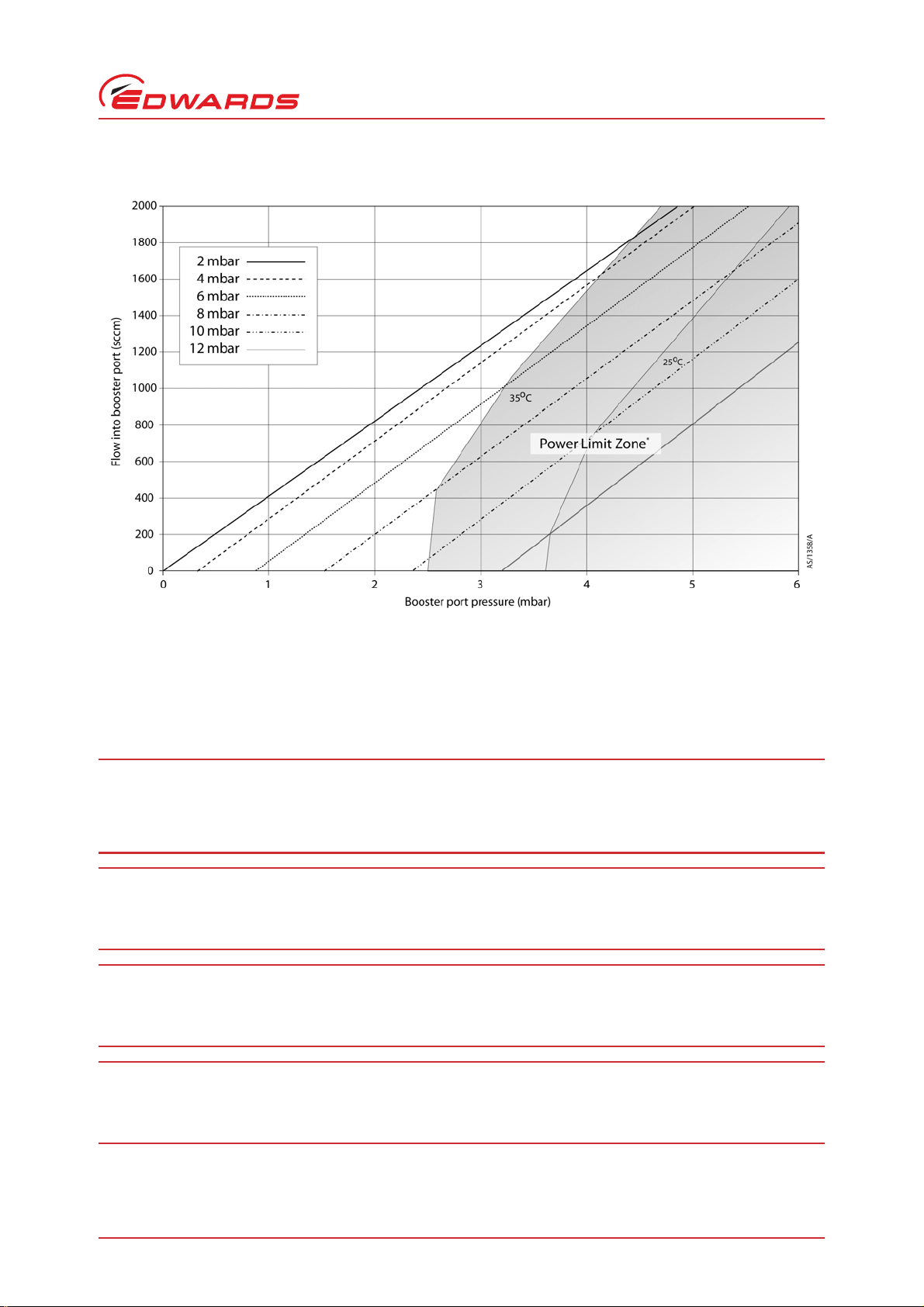
Figure 1 - Booster port performance with lines of constant backing pressure
Technical data
*
Power Limit Zone: The temperatures shown are pump local ambients. The tests were performed with a single
radial fan cooling the pump. If extra cooling is added, extra performance can be obtained. Exact limits will be
based on application requirements, cooling metho d and pump configuration; please consult Edwards to ensure
suitability. Also refer to Section 3.7 and 7.4 for cooling requirements and accessories.
2.2 Pumping med ia
If pumping hazardous gases or vapours, the customer must observe the safety recommendations
of the supplier of the gas or vapour. Vent hazardous gases and gas mixtures safely. Do not expose
people to these gases.
Do not pump explosive gas mixtures through the EXTPX split flow pump as the pump is not suitable
for this purpose.
If pyrophoric gases are pumped then the customer must supply adequate dilution with an inert gas.
It is the customers' responsibility to leak check their system to ensure that the process gases will
not escape to the atmosphere where this would cause a hazard.
© Edwards Limited 2007. All rights reserved. Page 5
Edwards and the Edwards logo are trademarks of Edwards Limited.
Page 14

B760-60-880 Issue A
CAUTION
CAUTION
CAUTION
WARNING
Technical data
Gases entering from different pump inlets may combine to cause dangerous mixtures.
An EXDC160 drive module is recommended for most applications. However, when pumpi ng high concentrations
of Argon (over 50% of gas mixture) an EXDC80 drive module is recommended to protect the pump against
overheating. If in any doubt, please contact your local Edwards Vacuum Representative.
Do not use the EXTPX split flow pump to pump particulates or condensable media. Deposition may occur within
the pump which will degrade pump performance and reduce the pump life.
Do not use the EXTPX split flow pump to pump gases containing more than 20% oxygen. If you do, the lubricant
will polymerise and the pump will fail prematurely.
Note: Concentrations of gases may be modified by the compression of the pump.
The pump is designed to pump the following residual gases normally used in high-vacuum systems:
z Air z Nitrogen z Carbon Dioxide
z Carbon Monoxide z Krypton z Helium
z Neon z Argon z Hydrogen
z Ethane z Propane z Butane
z Methane
You can use the pump to pump oxygen and water vapour, subject to the following conditions:
z Oxygen - The oxygen concentration must be less than 20% by volume; also refer to Section 2.4.
z Water vapour - You must ensure that vapour does not condense inside the pump.
If you wish to pump a gas not in the list above, co ntact your supplier for advice. If you do not contact your supplier,
you may invalidate the warranty on the pump. The pump is not suitable for pumping aggressive or corrosive gases.
Page 6 © Edwards Limited 2007. All rights reserved.
Edwards and the Edwards logo are trademarks of Edwards Limited.
Page 15

B760-60-880 Issue A
2.3 Vent gas specification and vent control data
Although the pump may be vented to atmosphere, high relative humidity of the air may greatly increase the
subsequent pump-down time. To reduce pump-down times you should vent the pump with dry, clean gases. Refer to
Table 3.
Table 3 - Vent gas and vent control data
Vent items Reference data
Vent gas Dry air, nitrogen, argon or other inert gases
Maximum dew point at atmospheric pressure -22°C
Maximum size of particulate 1
Maximum concentration of oil 0.1 parts per million
Time for rotational speed to reduce to 50% ≥15 seconds
Maximum purge gas pressure < 0.5 bar gauge (7 psig, 0.5 x 10
*
If you wish to use vent pressures in excess of this value, please consult Edwards.
µm
5
Pa gauge)
*
2.4 Purge gas specification and data
Technical data
When purged with an inert gas, the pumps can be used to pump oxygen in concentrations above 20% by volume.
Table 4 - Purge gas specification
Purge gas system items Reference data
Purge gas Dry nitrogen, argon or other inert gas
Maximum dew point at atmospheric pressure -22°C
Maximum size of particulate 1
Maximum concentration of oil 0.1 parts per million
Allowable purge gas flow (when required) 20- 150 sccm (0.33- 2.5 mbar l s
Recommended purge gas flow 25 sccm minimum (0.42 mbar l s-1, 42 pa l s-1)
Maximum allowable purge gas supply pressure 0.5 bar gauge (7 psig, 0.5 x 10⁵ Pa)
*
If you wish to use pressures in excess of this value, plea se consult Edwards.
µm
-1
, 33- 250 Pa l s-1)
*
2.5 Materials exposed to gases pumped
The following materials and component types are exposed to the gases pumped: aluminium alloys, steels, stainless
steels, fluoroelastomer and nitrile O-rings, hydrocarbon lubricant, felt, rare earth magnets, silicon nitride, phenolic
resin, and carbon-fibre reinforced epoxy resin.
© Edwards Limited 2007. All rights reserved. Page 7
Edwards and the Edwards logo are trademarks of Edwards Limited.
Page 16

B760-60-880 Issue A
1. Fan-mounting holes
2. Base mounting holes (remove feet)
3. Purge port
4. Booster port
5. Backing-pump port
6. Earth screw
7. Electrical connector
8. Side port
9. Main port
10.Vent port
Technical data
Figure 2 - Dimensions of B76061991 EXT400/200PX split flow pump - large main and side ports (units in mm)
Page 8 © Edwards Limited 2007. All rights reserved.
Edwards and the Edwards logo are trademarks of Edwards Limited.
Page 17

B760-60-880 Issue A
1. Fan-mounting holes
2. Base mounting holes (remove feet)
3. Purge port
4. Booster port
5. Backing-pump port
6. Earth screw
7. Electrical connector
8. Side port
9. Main port
10.Vent port
11.End port
Figure 3 - Dimensions of B76062991 EXT400/200PX split flow pump - large main and side ports plus end port
(units in mm)
Technical data
© Edwards Limited 2007. All rights reserved. Page 9
Edwards and the Edwards logo are trademarks of Edwards Limited.
Page 18

B760-60-880 Issue A
1. Fan-mounting holes
2. Base mounting holes (remove feet)
3. Purge port
4. Booster port
5. Backing-pump port
6. Earth screw
7. Electrical connector
8. Interstage port
9. Side port
10.Vent port
11.End port
Technical data
Figure 4 - Dimensions of B76067991 EXT400/200/30iPX - large side port and end port plus interstage port
(units in mm)
Page 10 © Edwards Limited 2007. All rights reserved.
Edwards and the Edwards logo are trademarks of Edwards Limited.
Page 19

B760-60-880 Issue A
1. Jacking point (M6 thread)
2. Purge port
3. Booster port
4. Backing-pump port
5. Earth screw
6. Electrical connector
7. Base mounting holes
8. Flange-mounting holes
9. Fan-mounting holes
10.Main port
11.Interstage port
12.Side port
13.Vent port
Figure 5 - Dimensions of B76053991 EXT400/200/30iPX - interstage cartridge pump with main, side ports plus
interstage port (units in mm)
Technical data
© Edwards Limited 2007. All rights reserved. Page 11
Edwards and the Edwards logo are trademarks of Edwards Limited.
Page 20

B760-60-880 Issue A
This page has been intentionally left blank.
Page 12 © Edwards Limited 2007. All rights reserved.
Edwards and the Edwards logo are trademarks of Edwards Limited.
Page 21

B760-60-880 Issue A
WARNING
3 Installation
3.1 Unpack and inspect
The pump weighs up to 12 kg (26 lbs). Appropriate care should be taken when lifting and moving
the pump to avoid injury.
Take care when unpacking the pump to avoid excessive sh ocks which co uld damage the beari ngs and re duce th e life
of the pump. The pump is supplied with the inlets and outlet sealed to prevent entry of dust and vapour. Do not
remove these seals until you are ready to install the pump on your vacuum system.
Open the cardboard box from the top. Once the box lid is open, remove the upper piece(s) of foam and cut open the
bag.
If the pump is damaged, notify your supplier and the carrier in writing within three days; state the Item Number of
the pump together with your order number and your supplier's invoice number. Retain all packing materials for
inspection. Do not use the pump if it is damaged.
Check that your package contains the items listed in Table 5. If any of these items are missing, notify your supplier
in writing within three days.
Installation
If the pump is not to be used immediately, store in suitable conditions as described in Section 6.1.
It is advised to retain all packing materials for use, should you return the pump for service.
Table 5 - List of items supplied
Quantity per pump
Description
EXTPX split flow pump 1111
Main (large) inlet screens (supplied fitted)2210
Interstage (small) inlet screens (supplied
fitted)
ISO160 inlet screen (supplied fitted) 0001
Inlet protection strips (supplied fitted)0002
Booster port O-ring and inlet strainer
(fitted)
Inlet O-ring seals (supplied loose) 2333
Covers 1221
B760-
61-991
0010
1111
B760-
62-991
B760-
67-991
B760-
53-991
Check (9)
© Edwards Limited 2007. All rights reserved. Page 13
Edwards and the Edwards logo are trademarks of Edwards Limited.
Page 22

B760-60-880 Issue A
CAUTION
Installation
3.2 Typical installation
Local legislation concerning the impact of the pump on the environment must be followed when installing and
removing the pump.
A typical pumping system with an EXTPX split flow pump is shown in Figure 6.
Page 14 © Edwards Limited 2007. All rights reserved.
Edwards and the Edwards logo are trademarks of Edwards Limited.
Page 23

Figure 6 - Schematic of a typical EXTPX split flow system
1. Vacuum system
2. Alternative position for
vent-valve
3. High vacuum gauge
4. Inlet screens
5. EXTPX split flow pump
6. Interstage port
7. Booster port
8. Booster port valve
9. PRX10 purge restrictor
10.Regulated purge gas supply
11.EXDC drive module
12.vent-valve
13.Controller (for example TIC)
*
14.Cooling fan (s)
15.Flexible bellows
16.Backing valve
17.Vacuum gauge
18.Foreli ne tra p (for OSRVP)
†
19.Backing-pump
20.Mist filter (for OSRVP)
*
TIC = Turbo and Instrument
Controller
†
OSRVP = Oil Sealed Rotary Vane
Pump
B760-60-880 Issue A
Installation
The accessories available for the EXTPX split flow pump are detailed in Section 7.4 and are shown in Figure 9.
© Edwards Limited 2007. All rights reserved. Page 15
Edwards and the Edwards logo are trademarks of Edwards Limited.
Page 24

B760-60-880 Issue A
WARNING
WARNING
WARNING
WARNING
WARNING
Installation
3.3 Connection to the vacuum system
Install the pump in the vacuum system before you connect the controller to the power supply. This
will ensure that the pump cannot operate and injure people during installation.
Under no circumstances must any part of the human body be exposed to a vacuum.
Carefully remove the pump from the packaging media and connect to the vacuum system.
3.3.1 Mechanical fixing
Ensure the EXTPX split flow pump is either securely fixed to the vacuum system via its inlet-flange
using all available mounting points, or that it is securely restrained to a fixed point. If the pump
were to seize when not securely mounted or restrained, the stored energy of the rotor (approx
20 kJ) could cause rapid movement of the pump, which may cause further damage and injury to
personnel.
If you wish to base-mount your pump, you will need to remove the 3 feet that are supplied fitted to the base of the
pump before mounting with qty. 5 M8 bolts. Refer also to the warning in Section 3.3.3.
3.3.2 Inlet screens
Inlet screens are supplied fitted to the pump.
The impeller blades on an EXTPX split flow pump are very sharp. The absence or removal of inlet
screens or strainers exposes the risk of injury from sharp edges or moving parts. Care should be
taken when handling the pump not to dislodge or damage the protective inlet screens.
For B76062991 and B76067991 only: There is no inlet screen fitted to the end of the chamber
pump and the blades of the turbo-pump are visible and accessible through the pump envelope at
this point. These blades represent a rotational safety hazard when the pump is operational and a
sharp edged hazard when the pump is stationary. Retain plastic transport covers over inlets until
ready to install in order to minimize any risk of injury.
Care must be taken to avoid foreign objects entering the pump when installing equipment to the
chambers.
Do not remove the inlet screens unless you can be sure that there is no danger that debris can fall into the pump.
To remove an inlet screen, carefully extract it from the inlet-flange using a bent wire hook. Once removed, a screen
is not reusable. Spares are available (refer to Section 7).
Page 16 © Edwards Limited 2007. All rights reserved.
Edwards and the Edwards logo are trademarks of Edwards Limited.
Page 25

B760-60-880 Issue A
CAUTION
WARNING
WARNING
1. Inlet screen
2. Inlet-flange
In the unlikely event of a pump fracture, it is possible that the inlet screen may not trap all debris
within the pump. Ensure that the system can contain any debris that may escape from the pump.
Figure 7 - Correct installation of inlet screen
Installation
3.3.3 Inlet connection and pump orientation
It is important that the pump is correctly orientated. Incorrect orientation may lead to premature pump failure.
Do not store or orientate the pump such that the pump inlets face towards the ground, nor store the pump such
that the end of the envelope faces towards the ground (with the pump body - containing electrical connector facing directly upwards). In either of these orientations it could be possible for oil used to lubricate the lower
bearing to escape from a reservoir at the base of the pump into the pump mechanism or vacuum system. This
may reduce performance and bearing life.
For base-mounting, use qty. 5 x M8 bolts tightened to a minimum torque of 10 Nm (7.5 lb ft) to
attach to the mounting. Use ISO898-1 material property class 12.9 or greater.
3.3.3.1 Inlet connection and pump orientation (non-cartridge pumps)
It is recommended that the pump is f lange mounte d. However, if this is not the case, please obs erve the warning in
Section 3.3.1. The exhaust port must not be tilted at more than 60° from the vertical position, (refer to Figure 8)
otherwise oil may leak into the pumping mechanism; refer to the Caution above.
Make sure that the pump inlets and all components fitted to the pump-inlets are clean and dust-free. If the pump-
inlets are not kept clean, the pump-down time may be increased or HV chamber pressures may not be achieved.
Use the O-rings supplied with the pump and use four M8 bolts tightened to a torque of 20 Nm (15 lb ft) to connect
the inlet-flange of the pump to the vacuum system.
© Edwards Limited 2007. All rights reserved. Page 17
Edwards and the Edwards logo are trademarks of Edwards Limited.
Page 26

B760-60-880 Issue A
WARNING
Installation
3.3.3.2 Inlet connection and pump orientation (cartridge pumps)
Use 6 x M8 fixing screws of appropriate length to attach the pum p to the vacuum chamber. Ensure
the chamber is robust enough to restrain the pump in the highly unlikely event of a rotor burst
where a peak torque of approximately 13,000 Nm may be transmitted to the chamber for a very
short time. It is the responsibility of the user to ensure that the vacuum system is capable of
containing the rotor fragments in the event of a catastrophic failure. Contact Edwards for further
information if required.
O-rings included with the cartridge pump must be fitted to the grooves before installing the cartridge pump into its
system. To ensure a proper seal between the inlets these should be untwisted, undamaged, dry, clean and dust-free.
Please refer to Edwards for recommended housing sizes.
Page 18 © Edwards Limited 2007. All rights reserved.
Edwards and the Edwards logo are trademarks of Edwards Limited.
Page 27

Figure 8 - Correct mounting attitude of the EXTPX split flow pump
B760-60-880 Issue A
Installation
© Edwards Limited 2007. All rights reserved. Page 19
Edwards and the Edwards logo are trademarks of Edwards Limited.
Page 28

B760-60-880 Issue A
CAUTION
CAUTION
WARNING
WARNING
Installation
3.3.4 Backing-port connection
The customer must ensure safe ducting of the backing-line if oil mist or hazardous substances are
present.
The EXTPX split flow pump must not be operated, or vented from a positive pressure gas supply,
with a restricted / blocked backing-line.
Do not use the EXTPX split flow pump with a backing pressure below 5 x 10⁻⁴ mbar (5 x 10⁻² Pa). Lower backing
pressures will increase the evaporation rate of the lubricating oil reducing the bearing life.
Use suitable vacuum tubing and connectors to connect the NW25 flange of the backing-port to your backing-pump.
If necessary, use flexible pipe or bellows to reduce the transmission of vibration from the backing-pump to the EXTPX
split flow pump.
The EXTPX split flow pump is suitable for use with Edwards Rotary Vane, Scroll or diaphragm backing-pumps. The
system performance may depend upon which pump is used, hence we recommend that you consult Edwards to help
select an appropriate backing-pump for your application.
3.3.5 Booster port connection
During operation the booster port must either be connected to the vacuum system or have a blanking flange attached.
Use suitable vacuum tubing and connectors to connect the NW25 flange of the booster port to your vacuum system
in the first instance. The strainer fitted is to prevent foreign object ingress. Refer also to the first Warning in
Section 3.3.2.
3.4 Vent options, vent-valve connection and control
To maintain the cleanliness of your vacuum system, we recommend that you vent the pump (or vacuum system)
whenever you switch the pump off.
If you manually vent the pump when it is at full rotational speed and the rate of pressure rise is too high, the
pump life may be reduced. When using the manual vent-valve supplied, we recommend that you either limit the
vent or only open the vent-valve after the EXTPX split flow pump speed has fallen to 50% of full rotational speed.
Do not vent from the backing-line, this may lead to contamination. If you vent into your vacuum system, and
use an oil-sealed rotary vane backing-pump, select a point upstream of the pump, to prevent oil back-streaming
from the backing-line.
Table 6 gives an indication of the appropriate orifice size to be fitted to the vent-valve for given vacuum system
volumes in order that the vent rate is kept within the limits given in Section 2.3.
Venting may be accomplished by one of the following means and by using the procedure below:
z Use a TAV5 or TAV6 solenoid vent-valve accessory (refer to Section 7) in the manual vent-valve position.
z Use a TAV5 or TAV6 solenoid vent-valve connected to a convenient flange on your vacuum system.
z Use an alternative valve, with an appropriate restriction, connected to your vacuum system. For further
details contact Edwards.
Page 20 © Edwards Limited 2007. All rights reserved.
Edwards and the Edwards logo are trademarks of Edwards Limited.
Page 29

B760-60-880 Issue A
WARNING
WARNING
WARNING
WARNING
1. Turn off the EXTPX split flow pump, but keep the backing-pump on.
2. When speed has fallen to 50%, open the vent-valve.
3. When the EXTPX split flow pump reaches standstill, the vent-valve may be closed.
Table 6 - Vent-restrictor orifice diameter (with atmospheric pressure at the inlet of the vent-valve)
Vacuum system volume (l) Orifice diameter (mm)
< 20 < 1.0
< 10 < 0.7
< 5 < 0.5
< 2 < 0.35
3.5 Purge gas connection
If you want to supply a purge gas to the pump, fit a vent port adaptor (refer to Section 7) in place of the blank plug
(refer to Figure 2 to 5). Connect your gas supply to the purge p ort . Your purge gas must comply with the limits/
specification given in Section 2.4. To limit the flow rate, use a fl ow controller or a pressure regulator and calibrated
flow restrictor. The PRX10 purge restrictor accessory ( refer to Section 7) is suitable for this purpose. Adjust the PRX10
as described in the instruction manual supplied with it.
Installation
3.6 Electrical installation
This product requires a separate power supply (not included). The power supply should be
adequately protected against a hazardous live condition (for example in case of a short circuit).
The customer must ensure that any electrical circuits are protected from dripping water caused
by condensation on cold surfaces.
It is the responsibility of the customer to ensure that the power supply used is correctly rated /
protected.
The customer must ensure appropriate routing of cables and pipe work to avoid slip/ trip hazards.
It is recommended that you fit a separate earth (ground) conductor to earth the EXTPX split flow pump and
accessories: use an uninsulated braid or a separate insulated green/yellow conductor, and use the M5 x 10 screw and
shake proof washer supplied (fitted in the earth hole on the pump) to secure the ea rth conductor to th e EXTPX split
flow pump and accessories.
For external protective earth systems: the installation should be permanent and use the same earth system as the
EXDC drive module; the impedance between the pump-body and earth connection point must be less than 0.1 Ohms.
Refer to the instruction manual supplied with the controller to complete the electrical installation.
© Edwards Limited 2007. All rights reserved. Page 21
Edwards and the Edwards logo are trademarks of Edwards Limited.
Page 30

B760-60-880 Issue A
CAUTION
CAUTION
CAUTION
WARNING
Installation
3.6.1 EXDC drive module
The customer must provide an emergency stop circuit to turn off power to the EXDC drive module.
Allow the pump to stop before removing the EXDC drive module.
An EXDC drive module requires connection to a suitably rated power supply. The EXDC drive module is designed to
allow a pumping system to operate in a fully automatic system.
3.6.2 TIC controller
The TIC controller can be used to provide the electrical supply to the EXDC (please refer to Section 7.4.3 for details).
The EXDC drive module connects to the back of the TIC via a 15 pin D-type connector.
The TIC controller is designed to allow a pumping system to be configured in a variety of ways, from a basic manuallyoperated system to a fully automatic system with remote control; refer to the TIC instruction manual.
3.7 Cooling
3.7.1 Introduction
The pump must be cooled either by forced-air or through a water-cooling accessory to prevent pump damage
and to maximize pump performance.
If you are using forced-air cooling to cool the pump you must ensure that there is an adequate supply of cooling-air
to the pump (refer to Section 3.7.2). During operation, if the tempera ture of any surface of the pump is hi gher than
60 °C, the cooling is inadequate and should be increased.
3.7.2 Forced-air cooling
Air-cooler accessories are available for the EXTPX split flow pu mp (refer to Section 7). Fit the air-cooler as described
in the instruction manual supplied with it (also refer to Figure 9). If you wish to use an alternative fa n for air-cooling,
ensure that the flow rate is above 80 m
module.
Pump performance may be affected if you do not cool the pump adequately.
3.7.3 Water-cooling
3h-1
(47 cfm) and is directed across the pump (base) and the EXDC drive
In the event of coolant failure, the pump must be allowed to cool down (to ambient temperature) before
restarting.
An accessory is available to enable the EXTPX split flow pump to be water cooled (refer to Section 7). Fit the
water-cooler as described in the instruction manual supplied with it. Ensure that the water supply is constant and
within the quality, temperature and flow rate limits detailed in Table 7.
Page 22 © Edwards Limited 2007. All rights reserved.
Edwards and the Edwards logo are trademarks of Edwards Limited.
Page 31

B760-60-880 Issue A
WARNING
Table 7 - Water-cooling block supply requirements
Parameter Specification
Quality Mechanically and optically clean with no deposits or
turbidity
pH Value 6.0 to 8.0
Maximum calcium carbonate concentration 75 parts per million
Maximum chloride concentration 100 parts per million
Minimum oxygen concentration 4 parts per million
Minimum water-cooling flo w rate (at 15 °C) 15 l h
Water temperature 10 to 20 °C
Maximum water pressure 5 bar (gauge), 72.5 psig, 5 x 10⁵ Pa (gauge)
Materials exposed to cooling-water Nickel plated brass
-1
3.8 Magnetic fields
Installation
If you wish to use the pump in or near magnetic fields please consult Edwards.
© Edwards Limited 2007. All rights reserved. Page 23
Edwards and the Edwards logo are trademarks of Edwards Limited.
Page 32

B760-60-880 Issue A
This page has been intentionally left blank.
Page 24 © Edwards Limited 2007. All rights reserved.
Edwards and the Edwards logo are trademarks of Edwards Limited.
Page 33

4 Operation
WARNING
WARNING
WARNING
WARNING
WARNING
Do not operate the EXTPX split flow pump unless it is connected to your vacuum system. If you do,
the pump-rotor can cause injury. The pump-rotor rotates at very high speeds and the rotating
blades might not be visible.
Do not move the pump whilst it is running. The gyroscopic forces generated by this movement can
cause excessive use of the back-up bearing and may result in catastrophic failure of the pump.
When power is restored following a power cut, the pump may restart automatically depending
upon the electrical configuration. The pump must remain connected to the vacuum system to
prevent risk of injury.
B760-60-880 Issue A
Operation
After power to the pump has been switched off, either through emergency or as a requirement,
the rotor will continue to spin at very high speeds. The rotor possesses considerable mechanical
energy until it slows down/ stops.
Do not remove the EXDC cable from the pump until the pump is completely at rest. If the pump is
still rotating when the cable is removed, the pump operator could be exposed to hazardous voltage
and potentially damage the EXDC drive module.
4.1 Start-up
Use the procedure below to start up a basic, manually-controlled pumping system with a manual vent-valve and an
EXDC drive module. Refer to the EXDC instruction manual.
1. Ensure any vent-valves are closed (including the manual vent-valve on the pump body).
2. Switch on the power to the air-cooler.
3. Start the backing-pump.
4. When the vacuum system pressure is approximately 10 mbar or less, start the E XTP X spli t f low pump . Fo r fas te r
ramp-up times, this pressure should be well below this figure.
5. The pump will then accelerate to full operating speed. The normal-speed LED on the EXDC drive module will
illuminate once nominal operating speed is reached.
Note: Refer to the controller manual if using the TIC controller.
© Edwards Limited 2007. All rights reserved. Page 25
Edwards and the Edwards logo are trademarks of Edwards Limited.
Page 34

B760-60-880 Issue A
CAUTION
Operation
4.2 Shut-down
Note: In an emergency only, open the vent-valve quickly to decelerate the pump-rotor in the shortest possible
time.
Use the procedure below to shut down a basic, manually-controlled pumping system with a manual vent-valve and a
TIC controller.
1. Close the valve in the backing-line connecting the EXTPX split flow pump to the backing-pump.
2. Switch off/ deactivate the start command to the EXTPX split flow pump.
3. When the EXTPX split flow pump rotational speed has fallen to below 50% of full rotational speed, turn the
manual vent-valve anti-clockwise slowly to open it. Refer to Section 3.4 for the venting procedure.
4.3 Safety interlocks and control system
The pump protection and safety interlock features are listed below. Refer to the instruction manual supplied with
the controller for a full description of these features.
4.3.1 EXDC drive module
The EXDC drive module monitors the temperature of the EXTPX split flow pump and the electrical power con sumption
of the pump. If the EXDC drive module detects excessive power consumption or temperature, the rotational speed
of the pump motor is reduced until the power and temperature return to normal.
4.3.2 TIC controller
The TIC controller monitors the pump rotational speed. If the EXDC drive module detects excessive power
consumption or temperature of the EXTPX split flow pump, it will reduce the operational speed of the unit. If this
speed is reduced to below 50% for a user-defined period of time, the TIC controller will automatically disconnect the
power supply. An error diagnostic message will then be displayed on the TIC controller. If the error message
‘Droop timeout’ is displayed on the TIC controller, switch off the backing-pump immediately and vent the EXTPX split
flow pump. Once the pump has stopped, rectify the cause of the failure and restart the pump. If the pump is hot,
allow sufficient time for it to cool before restarting.
4.4 Bakeout
Bakeout of envelopes would lead to damage of this product - do not bake.
Page 26 © Edwards Limited 2007. All rights reserved.
Edwards and the Edwards logo are trademarks of Edwards Limited.
Page 35

B760-60-880 Issue A
CAUTION
WARNING
WARNING
WARNING
WARNING
5Maintenance
The EXTPX split flow pump is not to be serviced by the customer. Pumps requiring servicing should
be returned to Edwards or serviced by a qualified Edwards engineer.
Allow the pump-rotor to stop, then disconnect the controller before you remove the pump from
your vacuum system for maintenance or fault finding procedures.
5.1 Introduction
The maintenance operations for the EXTPX split flow pump are described in the following sections. The inlet screens
and inlet-flange seals are available as spares (refer to Section 7). Fit the inlet screens as shown in Figure 7.
5.2 Bearing maintenance
Maintenance
The bearings will need to be replaced at the recommended service interval. This is typically more than 20,000 hours,
but may be less; this depends on the type of pumping duty on which the pump is used.
When the bearings need replacement, we recommend that you exchange your pump for a factory reconditioned
replacement. Alternatively, you can send your own pump to an Edwards Service Centre to have the bearings replaced.
Lubricants can contain toxic substances from the pumping media. The oil felt cartridge must be
disposed of in accordance with relevant regulations.
When you return the EXTPX split flow pump to an Edwards Service Centre please use the procedure included at the
end of this manual. Please note that the instruction to drain all fluids does not apply to the lubricant in the EXTPX
split flow pump oil-reservoir.
5.3 Rotor life
The fatigue life of the EXTPX split flow rotor is typically 40,000 to 50,000 cycles of acceleration fr om rest to full
speed and then back to rest. As a precautionary measure, Edwards recommends that pumps are returned for a
major service (rotor replacement) after 20,000 cycles or ten years, whichever occurs first.
5.4 Cleaning the pump
Clean the external surfaces of the EXTPX split flow pump in a well-ventilated location. When you
use cleaning solutions and solvents to clean the pump, observe all precautions specified by the
manufacturer. Avoid inhalation of any particulates which may be present in the pump.
© Edwards Limited 2007. All rights reserved. Page 27
Edwards and the Edwards logo are trademarks of Edwards Limited.
Page 36

B760-60-880 Issue A
CAUTION
Maintenance
Do not attempt to clean any parts of the EXTPX split flow pump other than external surfaces. Organic solvents
may damage internal pump components. Do not use abrasive materials to clean any part of the pump.
If the inside of the EXTPX split flow pump is contaminated, it may not be possible to achieve the specified ultimate
vacuum performance, or pump-down times may increase. In these circumstances the pump must be returned to an
Edwards Service Centre, where the pump will be dismantled and cleaned. Use the procedure given in the forms at
the end of this manual to return the pump.
You can use any organic solvent to clean the external surfaces of the EXTPX s plit flow pump. Edwards recommends
the use of non-CFC solvents such as isopropanol or ethanol. Use a cleaning solution which is suitable for the
contaminants on the pump surfaces.
For environmental reasons, keep wastage of cleaning solutions and solvents to a minimum.
5.5 Fault finding
Refer to Table 8 for the possible causes of faults and for the recommended actions to rectify faults. Table 8 is
applicable to a basic, manually controlled pumping system with an EXDC drive module.
Table 8 - Fault finding
Symptom Check Action
The impeller does not rotate after
giving a start signal.
‘Droop timeout’ displayed on th e
TIC.
Are the three red phase LEDs on the
EXDC drive module lit?
Is the EXDC correctly connected to
the EXTPX split flow pump?
Is the start signal being given
across the correct pins of the
EXDC logic interface plug?
None of the above. If all the above checks are OK but
Refer to Section 4.3.2. Refer to Section 4.3.2.
If not, check that power is supplied
to the EXDC.
If power is supplied but one or more
of the LEDs are not lit, then the
EXDC drive module may be faulty;
change the EXDC and try to start the
pump.
If the problem persists then the
EXTPX split flow pump may be faulty.
Consult Edwards or your supplier.
If the red LEDs are all lit, check that
the EXDC is properly connected to
the pump.
Refer to Section 3.4 of the EXDC
instruction manual for electrical
connections.
the impeller still does not rotate,
the EXTPX split flow pump may be
faulty; consult Edwards or your
supplier.
Page 28 © Edwards Limited 2007. All rights reserved.
Edwards and the Edwards logo are trademarks of Edwards Limited.
Page 37

Table 8 - Fault finding (continued)
Symptom Check Action
System operating pressure cannot be
reached.
The EXTPX split flow pump is very
noisy or there is excessive vibration,
or there is both.
Are any of the vacuum gauges
contaminated?
Is the pumping speed insufficient
owing to poor conductance between
pump and chamber/gauge, or too
large a chamber?
Is the backing pressure too high?
(refer to Table 2).
Is the high vacuum area of the
system contaminated?
Is the EXTPX split flow pump and/or
the EXDC drive module too hot?
Check the system for leaks and
contamination.
Are the booster and backing-ports
connected the right way round?
Is the pumps' rotational speed the
same as the resonant frequency of
the attached system?
Is the vibration being transmitted
from the backing-pump?
Is the noise irregular and getting
progressively worse?
If so, clean and replace them.
If so, increase the conductance or
reduce the volume.
Check for backing-line leaks. If the
backing pressure is too high, you may
need a larger backing-pump.
If so, clean the system.
If so, the pump and/or EXDC may
have gone into thermal limit;
increase the cooling to the pump
and/ or EXDC.
Clean any contaminated areas and
repair leaks.
Reconnect the ports correctly
(marked on the side of the body).
If so, change the resonant frequency
of the system.
If so, fit flexible bellows or a
vibration isolator in the backing-line.
If so, the bearing may be defective.
Consult Edwards or your supplier.
B760-60-880 Issue A
Maintenance
Is the EXTPX split flow pump making
a constant high-pitched noise?
None of the above. Consult Edwards or your supplier.
If so, the rotor may be out of
balance. Consult Edwards or your
supplier.
© Edwards Limited 2007. All rights reserved. Page 29
Edwards and the Edwards logo are trademarks of Edwards Limited.
Page 38

B760-60-880 Issue A
This page has been intentionally left blank.
Page 30 © Edwards Limited 2007. All rights reserved.
Edwards and the Edwards logo are trademarks of Edwards Limited.
Page 39

B760-60-880 Issue A
WARNING
6 Storage and disposal
6.1 Storage
Use the following procedure to store the pump.
1. Place protective covers over all ports, the main inlet, side inlet, booster port, exhaust, purge and vent ports.
2. Place the pump in its packing materials. For fastest pump-down when the pump is put back into service, seal the
pump inside a plastic bag together with a suitable desiccant.
3. Store the pump in cool, dry conditions, preferably not exposed to atmospheric air until required for use. When
required, prepare and install the pump as described in Section 3.
4. Keep the pump upright at all times to prevent the drainage of oil from the bearing reservoir.
5. Avoid long-term storage if possible. W hen long-term storage is necessary, the pump should be set up and run for
at least eight hours every six months.
6.2 Disposal
Storage and disposal
In the unlikely event of a failure of the pump-rotor, dust can be generated from the carbon fibre
reinforced components. In this event, use appropriate Personal Protective Equipment when
handling and disposing of the pump, and ensure that all pump inlets and outlets are capped off
before disposal.
Take appropriate action to avoid inhalation of any particles which may be present in the pump. Do
not incinerate the pump. The pump contains phenolic and fluorosilicone materials which can
decompose to very dangerous substances when heated to high temperatures.
Be aware that any hazardous gases may remain in the system after it has been switched off.
Dispose of the EXTPX split flow pump and any components and accessories safely in accordance with all local and
national safety and environmental requirements.
Particular care must be taken with any components which have been contaminated with dangerous process
substances.
© Edwards Limited 2007. All rights reserved. Page 31
Edwards and the Edwards logo are trademarks of Edwards Limited.
Page 40

B760-60-880 Issue A
This page has been intentionally left blank.
Page 32 © Edwards Limited 2007. All rights reserved.
Edwards and the Edwards logo are trademarks of Edwards Limited.
Page 41

B760-60-880 Issue A
7 Service, spares and accessories
7.1 Introduction
Edwards products, spares and accessories are avai lable from Edwards com panies in Belgium, Brazil, C anada, Peoples
Republic of China, France, Germany, Hong Kong, India, Israel, Italy, Japan, Korea, Singapore, Taiwan, United
Kingdom, USA and a worldwide network of distributors. The majority of these employ service engineers who have
undergone comprehensive Edwards training courses.
Order spare parts and accessories from your nearest Edwards company o r dist ri but or. When you order, p lease state
for each part required:
z Model and item number of your equipment.
z Serial number (if any).
z Item number and description of the part.
7.2 Service
Edwards products are supported by a worldwide network of Edwards Service Centres. Each Service Cent re offers a
wide range of options including: equipment decontamination; service exchange; repair; rebuild and testing to factory
specifications. Equipment which has been serviced, repaired or rebuilt is returned with a full warranty.
Service, spares and accessories
Your local Service Centre can also provide Edwards engineers to support on-site maintenance, service or repair of
your equipment.
For more information about service options, contact your nearest Service Centre or other Edwards company.
7.3 Spares kits
7.3.1 Inlet screens
Inlet screens are fitted to your pump as supplied to prevent damage from the entry of debris into the pump. The Item
Number of replacement inlet screens is given in Table 9.
7.3.2 Inlet strainer
An inlet strainer is supplied fitted into the booster port. The Item Number for replacement strainers is given in
Table 9.
7.3.3 Inlet-flange seal
The EXTPX split flow pump is supplied with inlet seals. The Item Number of replacement seals is given in Table 9.
Table 9 - Spares kits
Description Flange version Item Number
Chamber inlet screen spares kit
Cartridge inlet strip spares kit
Inlet strainer spares kit NW25 ISO-K A223-05-067
Chamber inlet O-ring spares kit
Cartridge inlet O-ring spares kit
B760-61-991, B760-62-991, B760-67-991
B760-53-991
B760-61-991, B760-62-991, B760-67-991
B760-53-991
B760-61-812
B760-53-812
B760-61-810
B760-53-810
© Edwards Limited 2007. All rights reserved. Page 33
Edwards and the Edwards logo are trademarks of Edwards Limited.
Page 42

B760-60-880 Issue A
Service, spares and accessories
7.4 Accessories
7.4.1 Installation
The accessories available for use with the EXTPX split flow pump are described in the following sections. Figure 9
shows how the accessories are fitted to an EXTPX split flow pump.
7.4.2 EXDC drive module
The Item Numbers of the EXDC drive modules are shown in Table 10.
Table 10 - EXDC drive module
Drive Module Item Number
EXDC 160 24 V D396-46-000
EXDC 80 24 V D396-45-000
7.4.3 TIC controller
A TIC controller can be used to supp ly p ower t o t he EXDC driv e modu le . Ref er to Table 11. To minimise pump ramp
up time and to maximise the pump performance the 200 W TIC controller is recommended.
Table 11 - TIC controller
Controller Voltage Item Number
TIC 200 W (Turbo controller) 90 - 264 V a.c. 47 to 63 Hz D397-12-000
TIC 200 W (Turbo and Instruments controller) 90 - 264 V a.c. 47 to 63 Hz D397-22-000
7.4.4 TAV vent-valve and vent port adaptor
Two solenoid-operated vent-valves are available for system venting. The valves are 24 V d.c., normally-open, and
can be driven automatically from the TIC controller. The solenoid-valve is fitted in place of the manual-valve , or
alternatively can be fitted with an adaptor (supplied with th e valve) and be used with any suitable NW10 flanged port
on your vacuum system. The vent port adaptor allows the vent port or the purge port to be used with any suitable
NW10 fitting. Refer to Table 12.
Table 12 - TAV vent-valve and vent port adaptor
Product Item Number Orifice diameter Vac system (litres)
TAV5 vent-valve B580-66-010 0.5 mm <5
TAV6 vent-valve B580-66-020 1.0 mm <20
NW10-1/8 inch BSP male adaptor B580-66-011
Page 34 © Edwards Limited 2007. All rights reserved.
Edwards and the Edwards logo are trademarks of Edwards Limited.
Page 43

B760-60-880 Issue A
7.4.5 VRX vent-restrictor
Use a VRX fixed orifice vent-restrictor to restrict the flow of vent gas into the EXTPX split flow pump. Refer to Table 6
for information on the selection of the correct VRX vent-restrictor. Also refer to Table 13.
Table 13 - VRX vent restrictor
Vent-restrictor Orifice diameter Item number
VRX10 0.1 mm B580-66-021
VRX20 0.2 mm B580-66-022
VRX30 0.3 mm B580-66-023
VRX50 0.5 mm B580-66-024
VRX70 0.7 mm B580-66-025
7.4.6 PRX purge-restrictor
A modified DN10NW centering-ring is available to filter the purge gas and restrict its flow rate to the recommended
flow of 25 sccm. The restrictor is suitable for all EXTPX split flow pumps fitted with a purge port. Refer to Table 14.
Table 14 - PRX purge restrictor
Service, spares and accessories
Purge-restrictor Flange size Item number
PRX10 NW10 B580-65-001
7.4.7 ACX air-cooler
A choice of ACX air-coolers can be fitted to the EXTPX split flow pump. Please refer to Section 3.7 to check the
suitability of air-cooling in a particular application. Both radial and axial air-coolers may be used simultaneously if
so desired and space allows. TICs can be used to provide power for one fan. Refer to Table 15.
Table 15 - ACX air-cooler
Air-cooler Item Number
ACX400 - axial air-cooler kit B580-53-405
ACX400 - radial air-cooler kit B580-53-455
7.4.8 WCX water-cooler
A water-cooler can be fitted to the EXTPX split flow pump. Please refer to Section 3.7.3 to check the suitability of
the water-cooling supply.
Table 16 - WCX water-cooler
Water-cooler Item Number
WCX250 B735-01-164
© Edwards Limited 2007. All rights reserved. Page 35
Edwards and the Edwards logo are trademarks of Edwards Limited.
Page 44

B760-60-880 Issue A
1. ACX400 axial air cooling accessory
2. ACX400 radial air cooling accessory
3. DN10NW adaptor
4. VRX vent restrictor
5. Manual vent-valve (fitted)
6. TAV solenoid vent-va lve
7. Purge plug (fitted)
8. PRX purge restrictor
9. DN10W adaptor
10.WCX water-cooler
11.EXDC drive module
Service, spares and accessories
Figure 9 - Installation of optional accessories
Page 36 © Edwards Limited 2007. All rights reserved.
Edwards and the Edwards logo are trademarks of Edwards Limited.
Page 45

Index
B760-60-880 Issue A
Index
A
Accessories ............................................... 34
ACX air-cooler ............................................ 35
B
Backing-port connection ............................... 20
Bakeout ................................................... 26
Bearing maintenance
Booster port connection
................................... 27
................................ 20
C
Cleaning the pump ...................................... 27
Connection to the vacuum system
Cooling
.................................................... 22
.................... 16
D
Disposal ................................................... 31
E
Electrical installation ................................... 21
EXDC drive module ............................22, 26, 34
F
Fault finding ..............................................28
Forced-air cooling ....................................... 22
I
Inlet connection and pump orientation .............. 17
Inlet connection and pump orientation
(cartridge pumps)
Inlet connection and pump orientation
(non-cartridge pumps)
Inlet screens
Inlet strainer .............................................33
Inlet-flange seal
Installation
.......................................18
.................................. 17
.........................................16, 33
.........................................33
............................................... 13
M
Magnetic fields ...........................................23
Maintenance
Materials exposed to gases pumped ....................7
Mechanical fixing ........................................ 16
.............................................. 27
P
PRX purge-restrictor .................................... 35
Pumping media ............................................5
Purge gas connection
Purge gas specification and data .......................7
................................... 21
R
Rotor life ................................................. 27
S
Safety interlocks and control system ................ 26
Scope and definitions .....................................1
.................................................... 33
Service
Service, spares and accessories
Shut-down ................................................ 26
Spares kits ................................................ 33
Start-up
Storage .................................................... 31
Storage and disposal .................................... 31
................................................... 25
....................... 33
T
TAV vent-valve and vent port adaptor ............... 34
Technical data .............................................3
TIC controller
Typical installation ...................................... 14
..................................22, 26, 34
U
Unpack and inspect ..................................... 13
V
Vent gas specification and vent control data .........7
Vent options, vent-valve connection and control
VRX vent-restrictor ..................................... 35
.. 20
W
Water-cooling ............................................ 22
WCX water-cooler
....................................... 35
O
Operation ................................................. 25
© Edwards Limited 2007. All rights reserved. Page 37
Edwards and the Edwards logo are trademarks of Edwards Limited.
Page 46

B760-60-880 Issue A
This page has been intentionally left blank.
Page 38 © Edwards Limited 2007. All rights reserved.
Edwards and the Edwards logo are trademarks of Edwards Limited.
 Loading...