

Edwards EXT70 Series, EXT70/ISO63, EXT250 Series, EXT70/NW50, EXT70/NW40 Instruction Manual
...
B722-01-880
Issue K Original
Instruction Manual
EXT70 and EXT250 Turbomolecular Pumps
Description Item Number
EXT70/NW40 B722-03-000
EXT70/NW50 B722-04-000
EXT70/ISO63 B722-01-000
EXT70/63CF B722-02-000
EXT250/ISO100 B736-01-000
EXT250/100CF B736-02-000


B722-01-880 Issue K
Contents
Section Page
1 Introduction .......................................................................................1
1.1 Scope and definitions ................................................................................................... 1
1.2 Description ................................................................................................................ 2
1.3 Vent options and vent control ......................................................................................... 5
2 Technical data ....................................................................................7
2.1 Operating conditions .................................................................................................... 7
2.2 Mechanical data .......................................................................................................... 7
2.3 Performance .............................................................................................................. 8
2.4 Pumping media ..........................................................................................................10
2.4.1 EXT70 and EXT250 pumps without gas purge .......................................................................10
2.4.2 EXT250 pumps with gas purge ........................................................................................10
2.5 Vent gas specification and vent control data ......................................................................11
2.6 Purge gas specification (for EXT250 only) ..........................................................................12
2.7 Cooling-water ...........................................................................................................12
Contents
3 Installation .................................................... ................................... 15
3.1 Unpack and inspect .....................................................................................................15
3.2 Typical installation .....................................................................................................15
3.3 Connect to the vacuum system .......................................................................................17
3.3.1 Inlet-screen ..............................................................................................................17
3.3.2 Mechanical fixing .......................................................................................................17
3.3.3 Base mounting ...........................................................................................................18
3.3.4 Inlet connection and orientation .....................................................................................18
3.3.5 Backing connection .....................................................................................................19
3.4 Vent-valve connection and control ..................................................................................19
3.5 Purge gas connection (EXT250 only) .................................................................................20
3.5.1 Connect the purge gas .................................................................................................20
3.5.2 Recommended purge gas flow ........................................................................................20
3.6 Electrical installation ..................................................................................................20
3.7 Cooling ...................................................................................................................20
3.7.1 Cooling methods ........................................................................................................21
3.7.2 Forced-air cooling ......................................................................................................21
3.7.3 Water-cooling ...........................................................................................................21
4 Operation ........................................................................................ 23
4.1 Start-up ..................................................................................................................23
4.2 Stand-by .................................................................................................................. 23
4.3 Shut-down ................................................................................................................ 24
4.4 Safety interlocks and control system ................................................................................24
4.5 Bakeout ................................................................................................................... 2 4
5 Maintenance ..................................................................................... 25
5.1 Introduction .............................................................................................................25
5.2 Bearing life ..............................................................................................................25
5.3 Rotor life .................................................................................................................25
5.4 Clean the pump .........................................................................................................25
5.5 Fault finding .............................................................................................................26
dcs/8146/09/08
© Edwards Limited 2007. All rights reserved. Page i
Edwards and the Edwards logo are trademarks of Edwards Limited.

B722-01-880 Issue K
Contents
6 Storage and Disposal ............................................. ..... ..... ..... ..... ..... ..... 29
6.1 Storage ...................................................................................................................29
6.2 Disposal ...................................................................................................................29
7 Service, Spares and Accessories .............................................................. 31
7.1 Introduction .............................................................................................................31
7.2 Service .................................................................................................................... 31
7.3 Spares .....................................................................................................................31
7.3.1 ISX inlet-screen .........................................................................................................31
7.3.2 WCX water-cooler ......................................................................................................31
7.3.3 Inlet-flange seals ........................................................................................................32
7.4 Accessories ............................................................................................................... 3 2
7.4.1 Installation ...............................................................................................................32
7.4.2 EXC Controller ........................................................................................................... 32
7.4.3 Pump-to-controller cable ..............................................................................................32
7.4.4 BX bakeout band ........................................................................................................34
7.4.5 FL20K foreline trap .....................................................................................................34
7.4.6 TAV vent valve and vent-port adaptor ..............................................................................34
7.4.7 ACX air-cooler ...........................................................................................................34
7.4.8 Vibration isolators ......................................................................................................35
7.4.9 PRX purge restrictor ....................................................................................................35
7.4.10 VRX vent-restrictor .....................................................................................................35
For return of equipment, complete the HS Forms at the end of this manual.
Illustrations
Figure Page
1 Cross-section view of EXT70 Turbomolecular Pump ................................................................ 3
2 Cross-section view of EXT250 Turbomolecular Pump .............................................................. 4
3 Maximum allowed rate of pressure rise during venting: system pressure .....................................11
4 EXT70 Turbomolecular Pump dimensions (mm) ....................................................................13
5 EXT250 Turbomolecular Pump dimensions (mm) ..................................................................14
6 Typical pumping system ...............................................................................................16
7 Correct installation of the inlet-screen .............................................................................17
8 Installation of optional accessories (and spares) ..................................................................33
Page ii © Edwards Limited 2007. All rights reserved.
Edwards and the Edwards logo are trademarks of Edwards Limited.

B722-01-880 Issue K
Tables
Table Page
1 Operating conditions data .............................................................................................. 7
2 Mechanical data .......................................................................................................... 7
3 EXT70 performance data ............................................................................................... 8
4 EXT250 performance data ..............................................................................................9
5 Vent gas data ............................................................................................................11
6 Purge gas data ...........................................................................................................12
7 Cooling-water data .....................................................................................................12
8 Checklist of items .......................................................................................................15
9 Vent-valve orifice diameter (with atmospheric pressure at the inlet of the vent-valve) ...................19
10 Pump cooling methods for different applications .................................................................21
11 Fault finding .............................................................................................................26
Associated publications
Contents
Publication title Publication number
EXT Pump Accessories D580-66-880
EXC Controllers D396-14-880
© Edwards Limited 2007. All rights reserved. Page iii
Edwards and the Edwards logo are trademarks of Edwards Limited.

B722-01-880 Issue K
This page has been intentionally left blank.
Page iv © Edwards Limited 2007 . All rights reserved.
Edwards and the Edwards logo are trademarks of Edwards Limited.

B722-01-880 Issue K
CAUTION
WARNING
1Introduction
1.1 Scope and definitions
This manual provides installation, operation and maintenance instructions for the Edwards EXT70 and EXT250
Turbomolecular Pumps. You must use the pumps as spe cified in this manual. Read this manual before you install and
operate the pump.
The EXT Turbomolecular Pumps are designed for use with an Edwards EXC Controller. Read this manual and the
instruction manual supplied with your EXC Controller before you attempt to install or operate the equipment. The
EXC Controller instructions contain details of how to set up a pumping system and how to cont rol accessories such a s
an air-cooler, vent-valve and bakeout band.
Important safety information is highlighted as WARNING and CAUTION instructions; you must obey these instructions.
The use of WARNINGS and CAUTIONS is defined below.
Warnings are given where failure to observe the instruction could result in injury or death to
people.
Introduction
Cautions are given where failure to observe the instruction could result in damage to the equipment, associated
equipment and process
In accordance with the recommendations of EN61010, the following warning symbols may appear on the p ump or its
accessories:
Warning - refer to accompanying documentation.
Warning - risk of electric shock.
Warning - hot surfaces.
Protective earth (ground).
The units used throughout this manual conform to the SI international system of units of measurement. Where
nitrogen purge flow rates are specified, the abbreviation ‘sccm’ is used to mean ‘standard cm
of 1 cm3 min-1 at an ambient temperature of 0 °C and at an ambient pressure of 1013 mbar (1.013 x 10⁵ Pa).
© Edwards Limited 2007. All rights reserved. Page 1
Edwards and the Edwards logo are trademarks of Edwards Limited.
3
min-1’: this is a flow

B722-01-880 Issue K
Introduction
1.2 Description
The EXT turbomolecular pumps are multi-stage axial-flow turbines, optimised for operation in molecular flow
conditions. The internal structures of the EXT70 and EXT250 Turbomolecular Pumps are shown in Figure 1 and
Figure 2.
The multi-stage, light alloy turbine rotor (12) is machined from one piece to form rows of angled blades fitted to a
central shaft (6). The blades of the rotor rotate between the blades of the stator. The stator assembly (11) is a series
of thin disks separated by spacer rings (10). The blades are angled so that the gas in the vacuum chamber is
compressed and is transferred from the pump-inlet to the outlet.
The rotor and stator blades have an open structure at the pump-inlet and a more closed structure at the outlet. This
configuration gives an optimum combination of pumping speed and compression when the pump is operated with
gases of both high and low molecular weight.
The rotor is driven by a high-efficiency, brushless d.c. motor. The motor (7) has a magnetized rotor fitted onto the
shaft, and a wound stator located in the pump-body. For the blades to be effective, their speed must b e close to the
thermal velocity of the gas molecules. The rotor is therefore rotated at up to 90000 r min
The rotor assembly is supported at the inlet end by a frictionless magnetic bearing (3) and by a precision ball bearing
(8) at the outlet end. The ball bearing is lubricated from an oil reservoir and wick mechanism (9).
EXT pumps are supplied with an inlet-screen (2) fitted in the bore of the inlet-flange. The inlet-scree n protects y ou
from the sharp blades and also protects the pump against damage caused by debris which falls into the pump.
-1
.
EXT pumps have a vent-port which you can use to vent the pump and your vacuum system to atmospheric pressure.
The vent-port introduces vent gas part way up the pump rotor to ensure maximum cleanliness even with
fluoroelastomer sealed vent-valves. The pump is supplied with a manual vent-valve fitted to the vent-port. As
described in Section 3.4, you can replace the manual vent-valve with a TAV5 solenoid-operated vent-valve (available
as an accessory: see Section 7.4.6).
The EXT250 pump has a purge-port (Figure 5, item 1) in the motor and bearing housing chamber. You can introduce
an inert purge gas through the purge-port to protect the bearing lubricant from the effects of high oxygen
concentrations. You can fit an optional purge restrictor to the purge-port to control the flow rate of the purge gas
and to filter the gas supply (see Section 7.4.9).
Electrical connection between the EXT and the EXC Controller is by a 19-way connector and a pump-to-controller
cable. The cable is a separate item and is available in a choice of lengths (see Section 7.4.3 for details).
The pump may be cooled using air-cooled or water-cooled optional accessories and the EXT70 may also be cooled by
natural convection to the surrounding air. Refer to Section 3 for guidance on applications and cooling requirements.
Pumps with a Conflat flange are supplied with a water-cooler.
All EXT pumps have thermal sensors to monitor the motor and pump-body temperature.
Page 2 © Edwards Limited 2007. All rights reserved.
Edwards and the Edwards logo are trademarks of Edwards Limited.
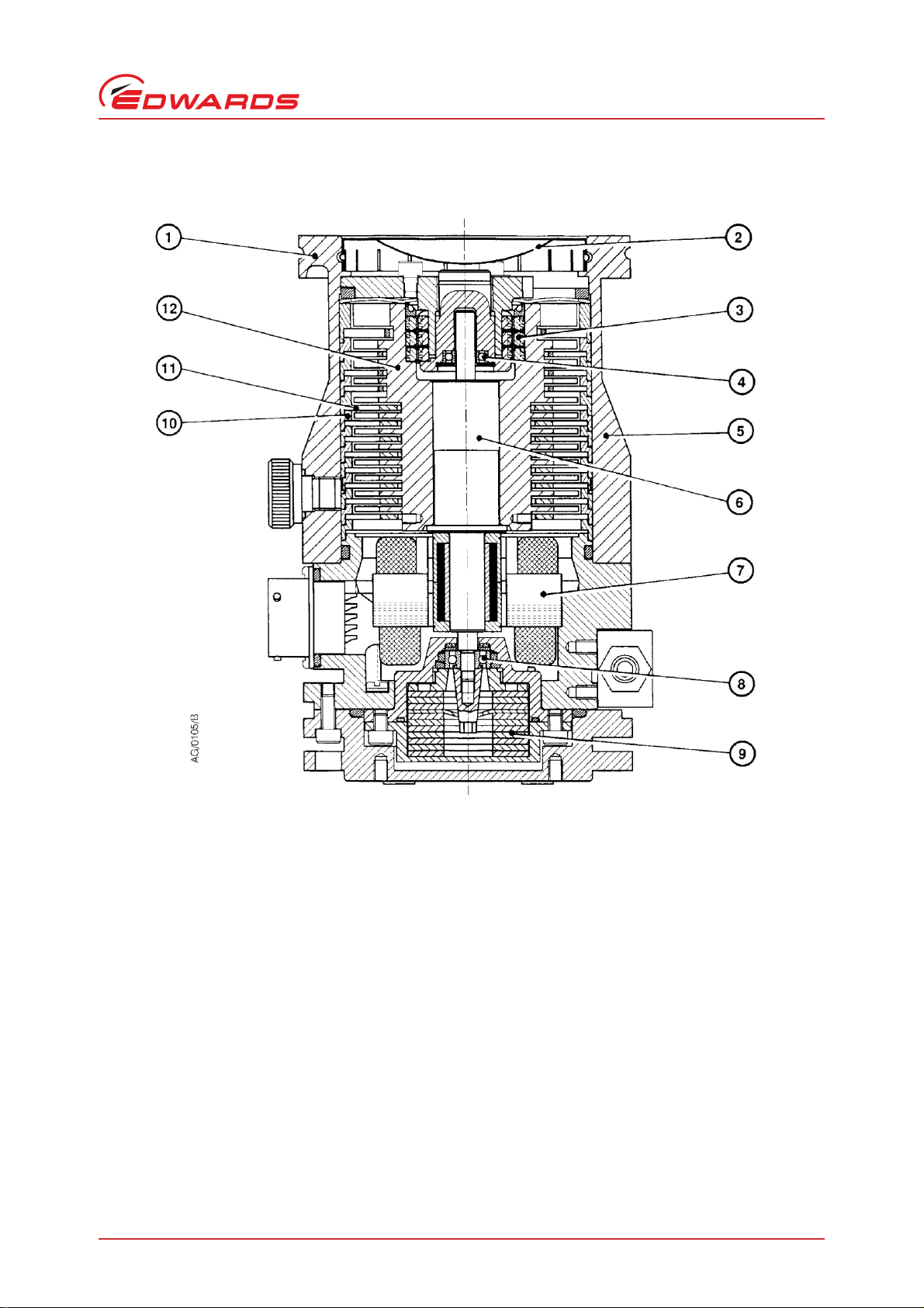
Figure 1 - Cross-section view of EXT70 Turbomolecular Pump
1. Inlet-flange
2. Inlet-screen
3. Magnetic bearing
4. Safety bearing
5. Envelope
6. Shaft
7. DC motor
8. Lower bearing
9. Oil reservoir
10.Spacer ring
11.Stator
12.R otor
B722-01-880 Issue K
Introduction
© Edwards Limited 2007. All rights reserved. Page 3
Edwards and the Edwards logo are trademarks of Edwards Limited.
B722-01-880 Issue K
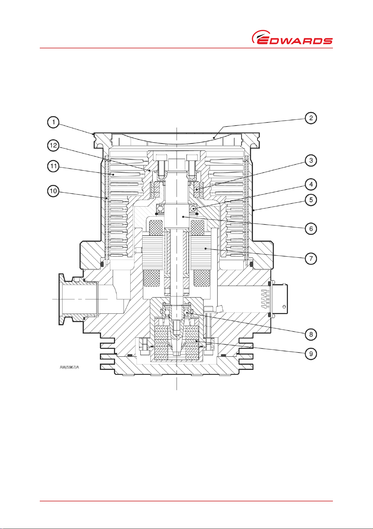
1. Inlet-flange
2. Inlet-screen
3. Magnetic bearing
4. Safety bearing
5. Envelope
6. Shaft
7. DC motor
8. Lower bearing
9. Oil reservoir
10.Spacer ring
11.Stator
12.Rotor
Introduction
Figure 2 - Cross-section view of EXT250 Turbomolecular Pump
Page 4 © Edwards Limited 2007. All rights reserved.
Edwards and the Edwards logo are trademarks of Edwards Limited.

B722-01-880 Issue K
1.3 Vent options and vent control
To maintain the cleanliness of your vacuum system, we recommend that, whenever you switch the pump off, you
vent the pump (or vacuum system) when the speed of the EXT pump is between full rotational speed and 50% of full
rotational speed. At and above 50% of full rotational speed, the rotor spins fa st enough to suppress an y backstreaming
of hydrocarbon oil from your bac king pump.
However, if you vent the pump w hen it is at full rotational speed and the rate of pressure ri se is too high, the p ump
life may be reduced. We therefore recommend that you either limit the rate of pressure rise in accordance with
Figure 3, or only open the vent-valve after the EXT pump speed has fallen to 50% of full rotational speed.
The rate of pressure rise cannot be controlled by the manual vent-valve, so if you use the manual vent-valve, you
must only open the vent-valve after the EXT pump speed has fallen to 50% of f u ll rotational speed.
If you use a TAV5 vent-valve, but you cannot limit the rate of pressure rise, you must only open the vent-valve after
the EXT pump speed has fallen to 50% of full rotational speed. If you use the EXC Controller to control your TAV5
vent-valve, configure the Controller to select this option: refer to Section 3.4 for more information. The
EXC Controller is factory set to vent when the EXT pump is at 50% of full rotational speed after you have selected
Stop.
Introduction
© Edwards Limited 2007. All rights reserved. Page 5
Edwards and the Edwards logo are trademarks of Edwards Limited.

B722-01-880 Issue K
This page has been intentionally left blank.
Page 6 © Edwards Limited 2007. All rights reserved.
Edwards and the Edwards logo are trademarks of Edwards Limited.

2Technical data
2.1 Operating conditions
Table 1 - Operating conditions data
Maximum inlet flange temperature 100
Maximum magnetic field 5 mT
Ambient operating temperature
Water-cooling 5 to 40
Free convection cooling (EXT70 only) 0 to 30
Forced-air cooling 0 to 35
Maximum operating humidity
o
Ambient temperature up to 31
Ambient temperature up to 40 oC50%
Minimum backing pump displacement 0.6 m
Recommended backi n g pump
Operating attitude Vertical and upright through to horizontal
Maximum operating altitude 2000 m
Noise level (at 1 m) < 50 dB(A)
Installation category EN61010 part 1, Category 1
Pollution degree EN61010 part 1, Category 2
Equipment type Fixed Equipment, for indoor use only
*
A larger backing-pump may be required for maximum throughput.
C80%
*
o
C
o
C
o
C
o
C
3 h-1
(EXT70 DN40NW/DN50NW)
1.3 m3 h-1 (EXT70 DN63CF/DN63ISO-K)
4.6 m3 h-1 (EXT250 DN100CF/DN100ISO-K)
E2M0.7 (EXT70 DN40NW/DN50NW)
E2M1.5 (EXT70 DN63CF/DN63ISO-K)
E2M5 (EXT250 DN100CF/DN100ISO-K)
B722-01-880 Issue K
Technical data
2.2 Mechanical data
Table 2 - Mechanical data
Dimensions See Figure 4 and Figure 5
Inlet-flange: EXT70 DN40NW, DN50NW, DN63CF or DN63ISO-K
Inlet-flange: EXT250 DN100CF or DN100ISO-K
Outlet-flange DN16NW (EXT70), DN25NW (EXT250)
1
Vent-port
Purge-port (EXT250 only) DN10NW
Mass: EXT70 DN40NW/DN50NW 1.4 kg
EXT70 DN63CF 3.4 kg
EXT70 DN63ISO-K 1.5 kg
EXT250 DN100CF 5.6 kg
EXT250 DN100ISO-K 8.0 kg
© Edwards Limited 2007. All rights reserved. Page 7
Edwards and the Edwards logo are trademarks of Edwards Limited.
/8 inch BSP
 Loading...