

Page 1
Mechanical Pan & Tilt IP Camera
User Manual
1
Page 2

C A T A L O G
Chapter I: Familiar with your Internet IP Camera............................................................4
1.1 Package Contents.....................................................................................................4
1.2 Basic Introduction......................................................................................................4
1.3 Product Highlights.....................................................................................................5
1.4 Familiar with Key Components ......................................................................................6
1.5 Descriptions for LED Indicators ...................................................................................10
1.6 Camera Installation......................................................................................................11
Chapter II: Using Web Management Interface...............................................................14
2.1 Camera Settings..........................................................................................................14
2.2 Pan and Tilt..................................................................................................................17
2.2.1 Preset Points..............................................................................................17
2.2.2 Grand Tour..................................................................................................18
2.3.3 Dynamic DNS.............................................................................................27
2.3.4 UPnP..........................................................................................................28
2.3.5 Login Free ..................................................................................................29
2.4.1 Motion Detection.........................................................................................31
2.5.1 Camera Information....................................................................................36
2.5.2 Date / Time Setting.....................................................................................37
2.5.3 Utilities........................................................................................................37
2.5.4 Status ..........................................................................................................39
2.6 Account........................................................................................................................43
2.7 SDHC…………………………………………………………………………………………..42
2.7.2 Sp ace Alarm…………………………………………………….…………………………..43
2.7.3 File Management...................................................................................................... 43
Chapter III: Using Surveillance Software.......................................................................43
3-1 Installing IP Camera Surveillance Software.................................................................44
3-2 Using IP camera surveillance software ........................................................................47
3-3 Configure IP camera surveillance software..................................................................49
3-3-1 Configure cameras.....................................................................................49
3-3-2 General Settings ........................................................................................55
3-4 Change Display Layout ...............................................................................60
3-5 Full-screen modes.......................................................................................62
3-6 Scan ............................................................................................................63
3-7 Zoom-in / Zoom-out.....................................................................................64
3-8 PTZ..............................................................................................................65
2
Page 3

3-9 Snapshot .....................................................................................................66
3-10 Recording..................................................................................................66
3-11 Video Playback..........................................................................................67
Chapter IV: Appendix.......................................................................................................68
4.1 Specification.................................................................................................................68
4.2 Troubleshooting...........................................................................................................69
3
Page 4

Chapter I: Familiar with your Internet IP Camera
1.1 Package Contents
Thank you for purchasing this IP camera! Before you start to use this IP camera, please check the package
contents. If anything is missing, please contact the dealer of purchase and return the package to claim for
missing contents.
Item Name Quantity
1 IP Camera 1
2 Antenna 2
3 Power Adapter 1
4 Ethernet Cable 1
5 Driver and User Manual CD-ROM 1
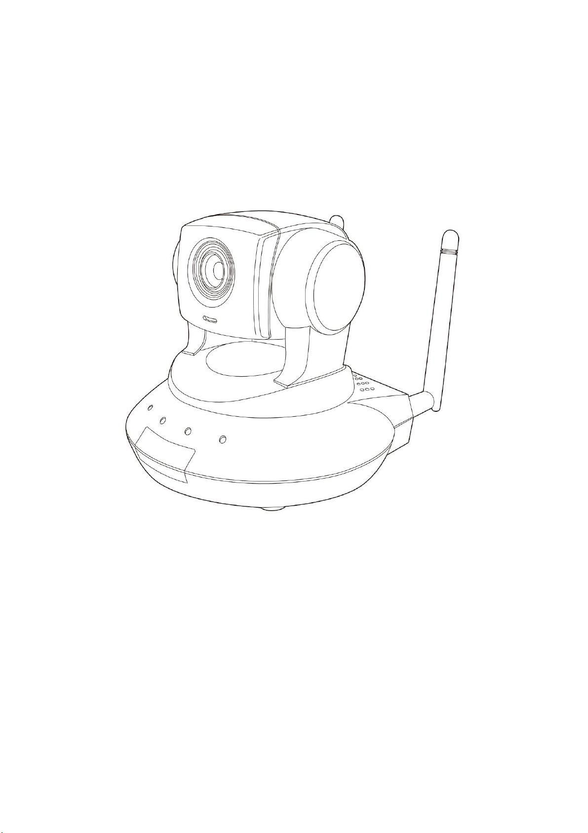
1.2 Basic Introduction
Thank you for purchasing this Internet IP camera! This IP camera is an ideal product for all kinds of
video-surveillance purposes, like home/office safety, kid/pet monitoring, and remote video acquire etc. Unlink
conventional close-circuit vide camera, you’re not limited to the length of cable! Once this IP camera is
connected to Internet, you can receive video from anywhere in the world where Internet access is available.
If you have problem installing a new cable from the place the came ra is i nstalled to your monitoring computer,
don’t worry! This IP camera also support s wireless network, that is, you can link to this camera wirele ssly! You
only have to provide this IP camera with 12V power by the power adapter that comes with the product
package, and you don’t have to set a new network cable between the IP camera and monito ring computer .
Worry about the content will be intercepted by unauthorized person when the video is transmitted over the air?
That’s also not a problem! Unlink conventional analog wireless camera, which video will be intercepted by
anyone who got a compatible video receiver, this IP camera supports data encryption (WEP & WPA), which
will provide ultimate data security level. All video transmitted over t he air i s encrypted; therefore no o ne will be
able to get the video captured by the IP camera, expect yourself.
Some people may concern that there will be some places which will not be covered by camera, but this
problem is completely solved by this IP camera. With built-in pan-tilt function, you can point the camera to the
position where you wish to look at with user interface. You can even define a preset path, and the camera will
cruise along the path you defined. You can discover more useful functions in next section!
4
Page 5

1.3 Product Highlights
No pre-loaded software required - all you need is a browser like Internet Explorer 6 (and above, with
plug-in installed).
With supplied video surveillance software, you can connect up to 16 video cam eras and view images
captured by every camera at the same time.
Supports 3 video resolutions: XGA (1024 x 768), VGA (640 x 480), and QVGA (320 x 240).
Anti-flicker function (eliminates flash caused by fluorescent lights, 50 / 60Hz selectable).
Video control functions, like brightness and zoom-in / zoom-out.
Pan-tilt control.
Wired and wireless network (802.11b / 802.11g / 802.11n) support, supports up to 100Mbps for wired
network and 100Mbps for wireless network.
Wireless data encryption (WEP / WPA)
Supports DHCP and PPPoE protocol, you can also assign a fixed IP address to the camera also.
Supports Dynamic DNS (used to allocate the IP camera’s Internet address, when the ISP you’re using
does not assign you with a fixed Internet address).
Supports UPnP, Windows XP (and above) will discover this IP camera in network neighbor
automatically.
Send captured picture and video by Email or FTP when motion is detected.
Configurable motion detection sensitivity (6 levels from most sensitive to least sensitive).
Built-in real-time clock, date and time information will be recorded with every captured picture / video clip
(also supports auto time synchronization via network time protocol).
Upgradeable firmware - enjoy new functions without buying a new camera!
Supports up to 16 users, and you can set different password to different user.
Usage and event logging.
5
Page 6
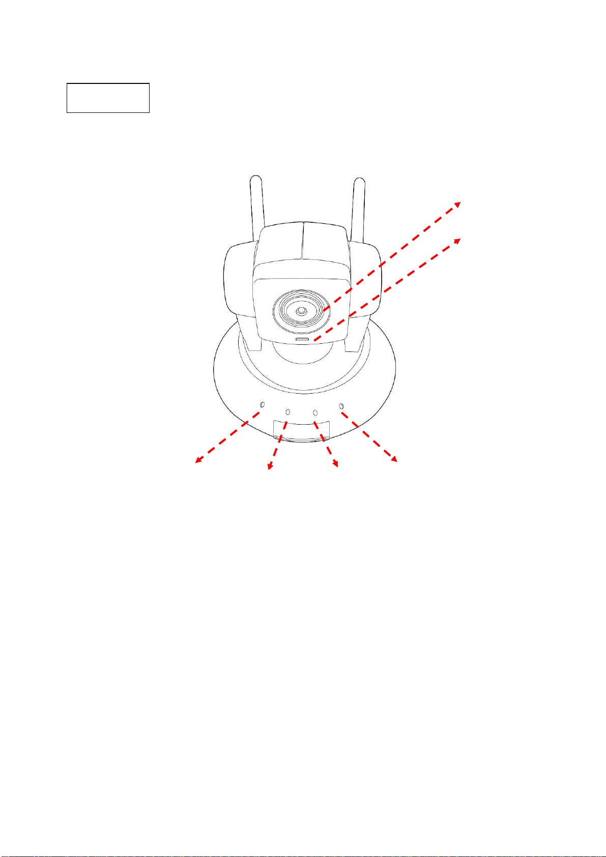
1.4 Familiar with Key Components
Front View
The picture is similar with IC-7000PT
Focus Ring
Microphone
IC7000PTn Power LED Audio LED LAN LED WLAN
IC7000PT Power LED Audio LED ACT LED LAN
z Power LED: Indicates power status
z Audio LED: Indicates Audio status
z LAN LED: Indicates LAN activity
z ACT LED: Indicates Data activity
z WLAN LED: Indicates Wireless LAN activity
z Focus Ring: Adjusts focus
6
Page 7
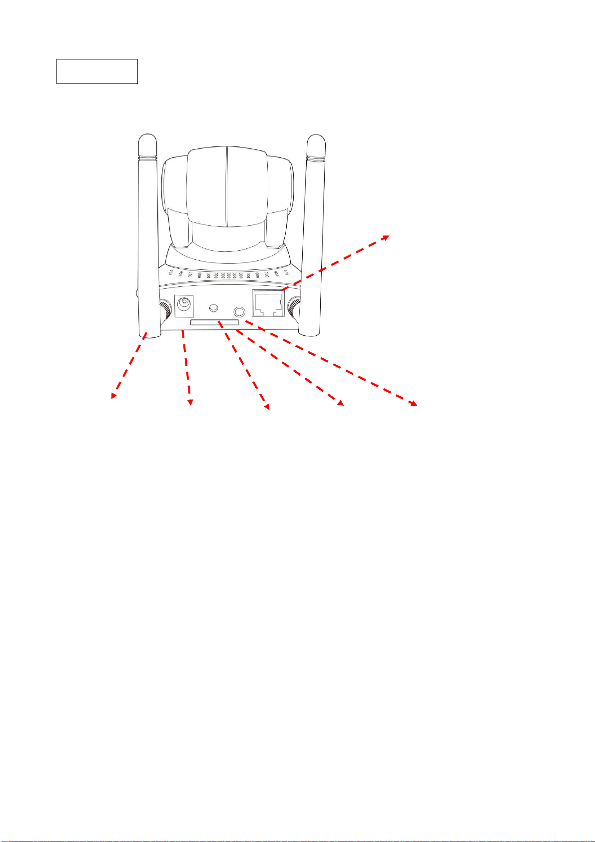
Back V iew
Ethernet
Connector
Antenna Power Connector WPS Button SD Card Slot Audio Connector
z Antenna: Connects to supplied antenna (IC-7000PTn only)
z Power Connector: Connects to A/C power adapter
z SD Card Slot: Accepts SD / SD-HC memory card for image / video storage
z WPS Button: click the bottom on IP Cam and click it on the AP you want to connect for wireless
z Audio Connector: Connects to external speaker for audio output
z Ethernet Connector: Connect to your local area network
7
Page 8
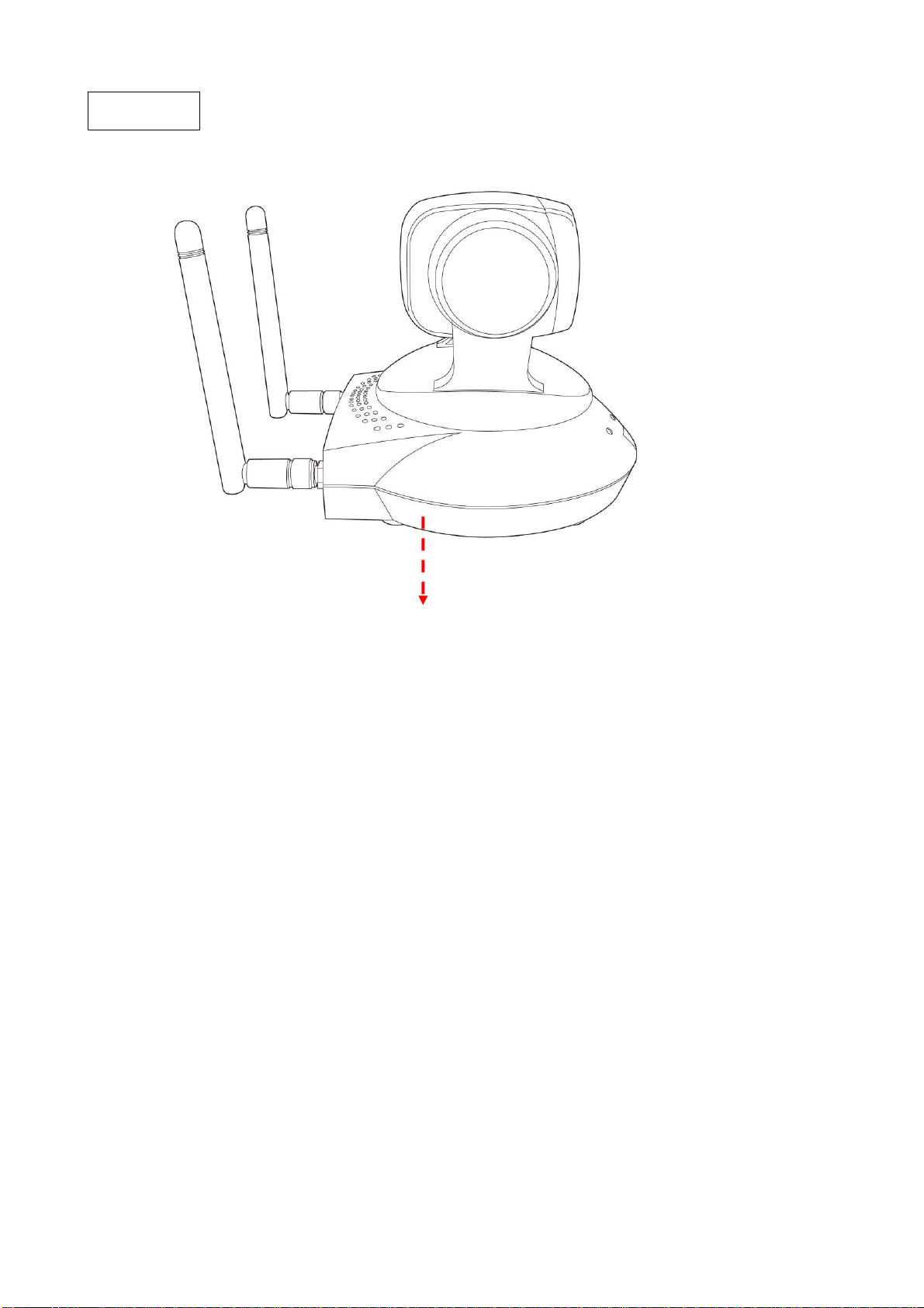
S
ide V iew
Reset Button: Press the button with pen nib and hold for 5 seconds to reset the camera settings to factory
default value.
Reset Button
8
Page 9
Bottom V iew
Tripod Connector: Connects to tripod to secure the camera when the camera is not put on a horizontal
surface.
Tripod Connector
9
Page 10

1.5 Descriptions for LED Indicators
For IC-7000PTn
LED Name Status Description
Power
Off Camera is not powered (camera off)
On Camera is correctly powered (camera on)
Off LAN port not in use
LAN
On LAN port in use
Flash Transferring dat a via LAN port
Off Wireless LAN not in use
On Wireless LAN in use
WLAN
Flash at low
speed
Waiting for WPS connection from AP and flash
speed is once a second.
Flash Transferring dat a via wireless LAN
Off Audio function is disabled (Volume 0)
Audio
On Audio function is enabled
Flash Two way audio is working
For IC-7000PT
LED Name Status Description
Power
ACT
Off Camera is not powered (camera off)
On Camera is correctly powered (camera on)
Off Data is not transfer
On Transferring data
Off LAN not in use
LAN
On LAN in use
Off Audio function is disabled (Volume 0)
Audio
On Audio function is enabled
Flash Two way audio is working
10
Page 11
1.6 Camera Installation
Please follow the following instructions to set your IP camera up.
1. Unpack the product package and check if anything’s missing.
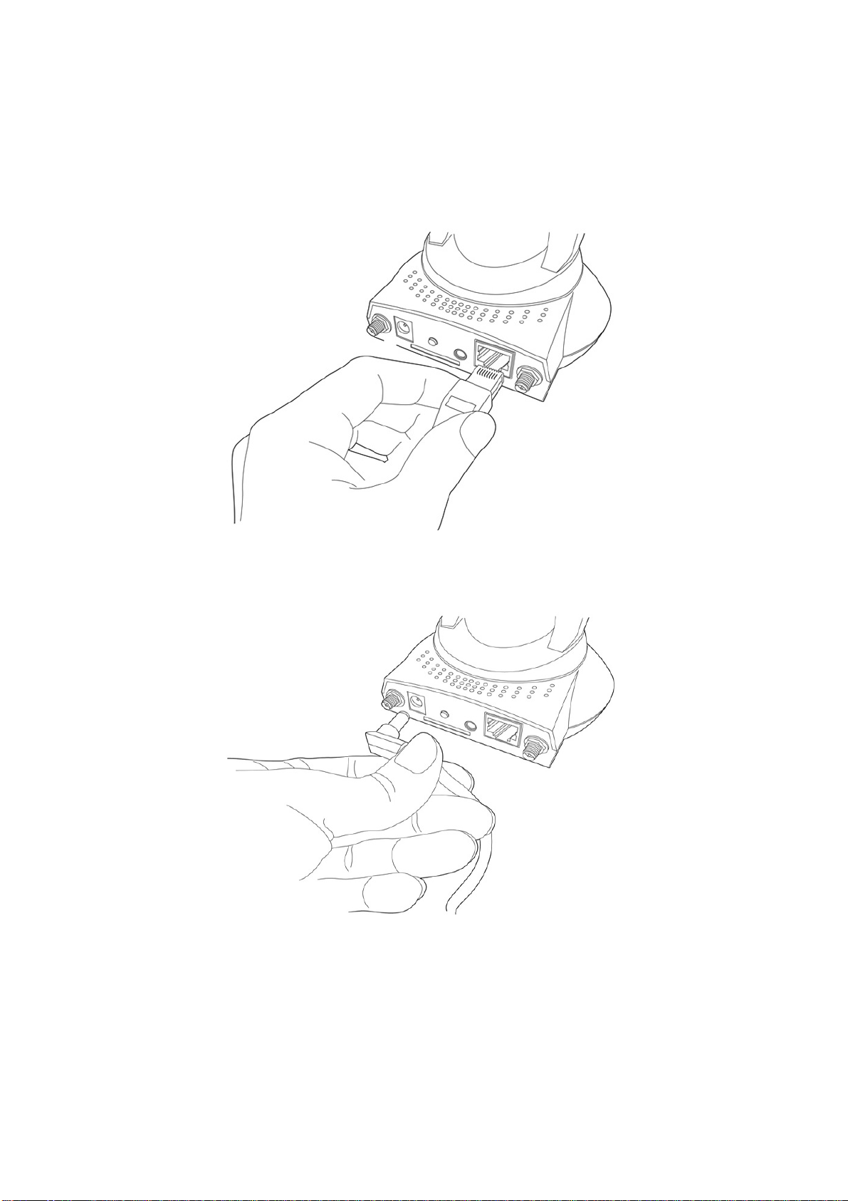
Connect the Ethernet cable to your local area network, and connect the other end to the LAN jack of this
IP camera.
NOTE: You can skip this step if you plan to use wireless LAN only.
2. Plug the power adapter to wall socket, and connect the power connector to the power jack located at the
bottom of the IP camera.
11
Page 12
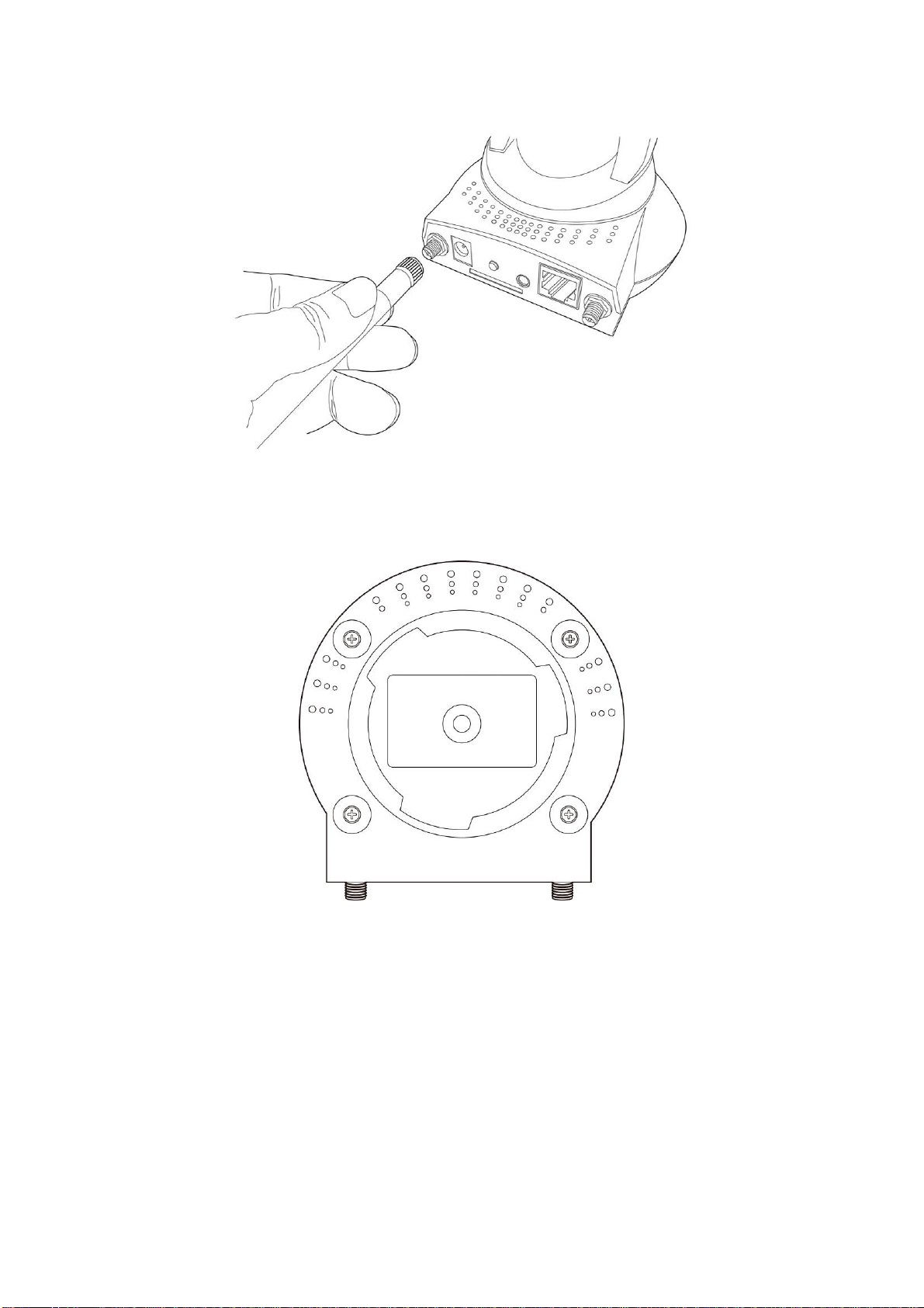
3. Connect two antennas to the antenna bases, which is located at the back of this IP camera.
4.
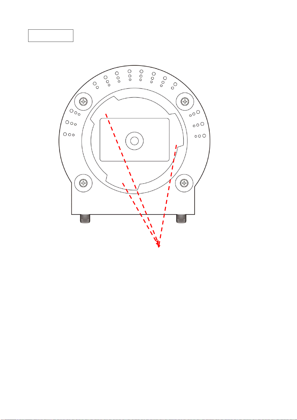
Place the camera at a secure place, and point the camera to the place you wish to monitor. If you wish to
hang the camera on the ceiling or wall, please use the tripod connector (located at the bottom of the
camera) to secure the camera.
12
Page 13
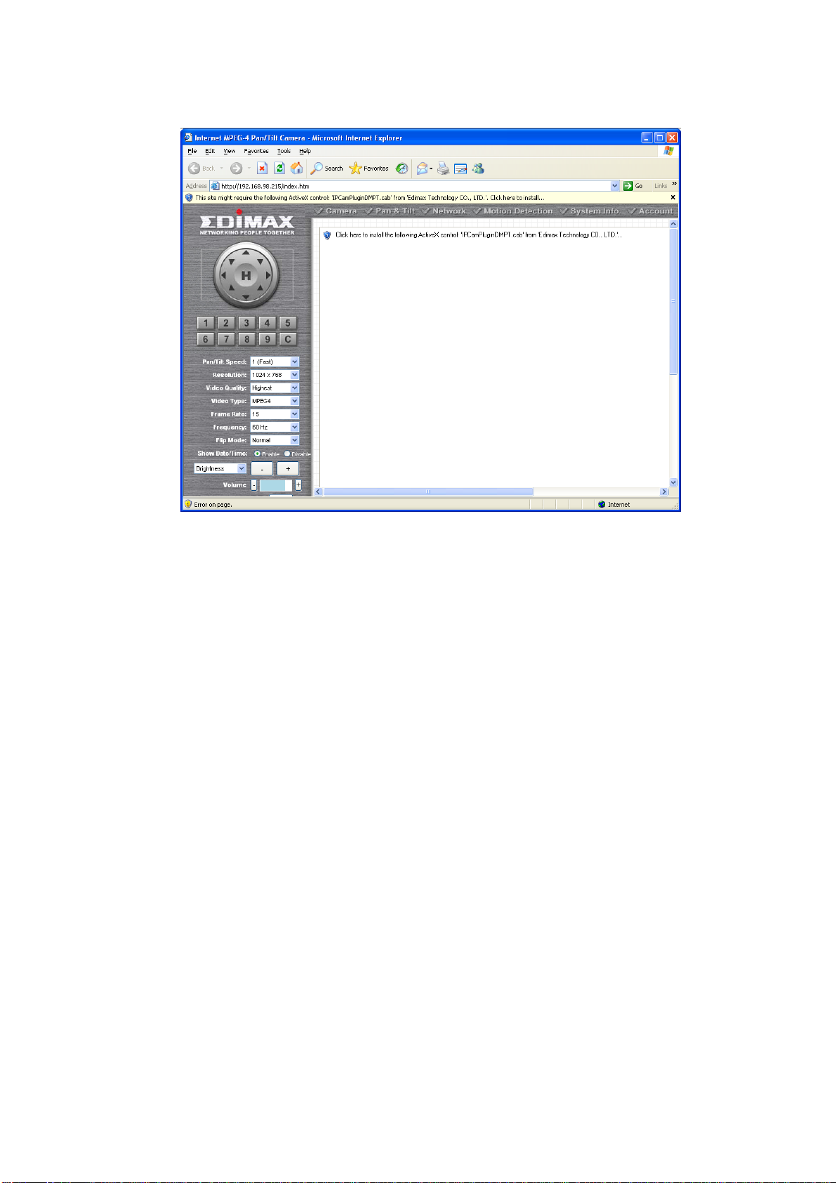
5. Launch Internet Explorer on your computer, and following the instructions given in next section to set the
IP camera.
13
Page 14
Chapter II: Using Web Management Interface
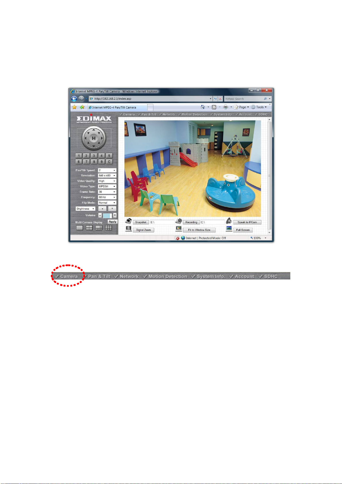
2.1 Camera Settings
The first menu after you logged onto web management interface is ‘Camera’, and this is the only menu you
can see the real-time image from camera.
You can always back to this menu by clicking ‘Camera’ on the top of web management interface.
14
Page 15

The descriptions of every setting in this menu will be given below:
Item Description
Specifies the moving speed when you use pan / tilt function to point the
camera to a new direction. Available options are 1 (fastest) to 5 (slowest).
Pan/Tilt Speed
Select 1 to move the camera by a faster speed, but you will not be able to
control the movement precisely. If you wan to move the camera in a more
accurate manner, select a slo wer speed.
Specifies the video resoluti on. Available options are 1024 x 768, 640 x 480,
and 320 x 240 @ MPEG4 or 1280x1024, 640x480 and 320x240 @ MJPG
Higher resolution provides more details about the objects captured by
camera, but will consume more bandwidth, which wil l make the image
Resolution
refreshes very slow .If you have a slow Internet connection, you may want to
use a lower resolution to make the image refresh faster.
Selecting the resolution of 320 x 240 may cause the image become too
small on a high-resolution computer monitor. If you want to save bandwidth
while selecting a high resolution, please select a lower image quality (see
below).
Specifies the quality of image captured by camera. There are 5 options from
‘Highest’ to ‘Lowest’.
Video Quality
Just like resolution, higher image quality will provide more details ab out the
objects captured by camera, but the cost is bandwidth. Sometimes you just
want to see if there’s anything moving at the place where camera points to,
you can select a lower image quality to get a higher image refresh rate.
Video Type
Frame Rate
Frequency
Flip Mode
Brightness /
Saturation /
Sharpness
Volume
Select the video encoding type. Available options are ‘MJPEG’ and
‘MPEG4’.
The highest image refresh rate of this IP camera is 30, which is the same as
TV. However, if you are using an Internet connection with limited bandwidth,
and you don’t need a fast image refresh rate, you can limit the maximum
refresh rate (frame rate) to a certain value.
Available options are 30, 15, 10, 5, and 3.
If the place where this IP camera points to has a (or more) fluorescent
light(s), the image may look flashing. In this case, you can adjust this setting
to the frequency of electrical power; this can improve the image quality
effectively. If you don’t know which one you should use, just try any of them
and select one with less flicker.
If you’re not putting this camera on a horizontal surface but hang the camera
on the ceiling or wall, you can use this function to rotate the displaying
image.
Select brightness, saturation, and sharpness from dropdown menu, and
click ‘ - ' or ‘ + ‘ button to increase or decrease brightness / saturation /
sharpness setting value. In certain environment, adjust brightness,
saturation, and / or sharpness will help improve video quality.
Adjust the volume of audio output. Press ‘+’ or ‘-‘ button to increase or
decrease volume.
Multi-Camera Display
Click one of these buttons to select 1 / 4 / 6 / 9 multi-camera view. See
chapter 2.2.3 for detailed instructions.
15
Page 16
NOTE: When you change any setting(s) listed above, please click ‘Apply’ button so the
change(s) will take effect. For following functions, changes will take effect right away.
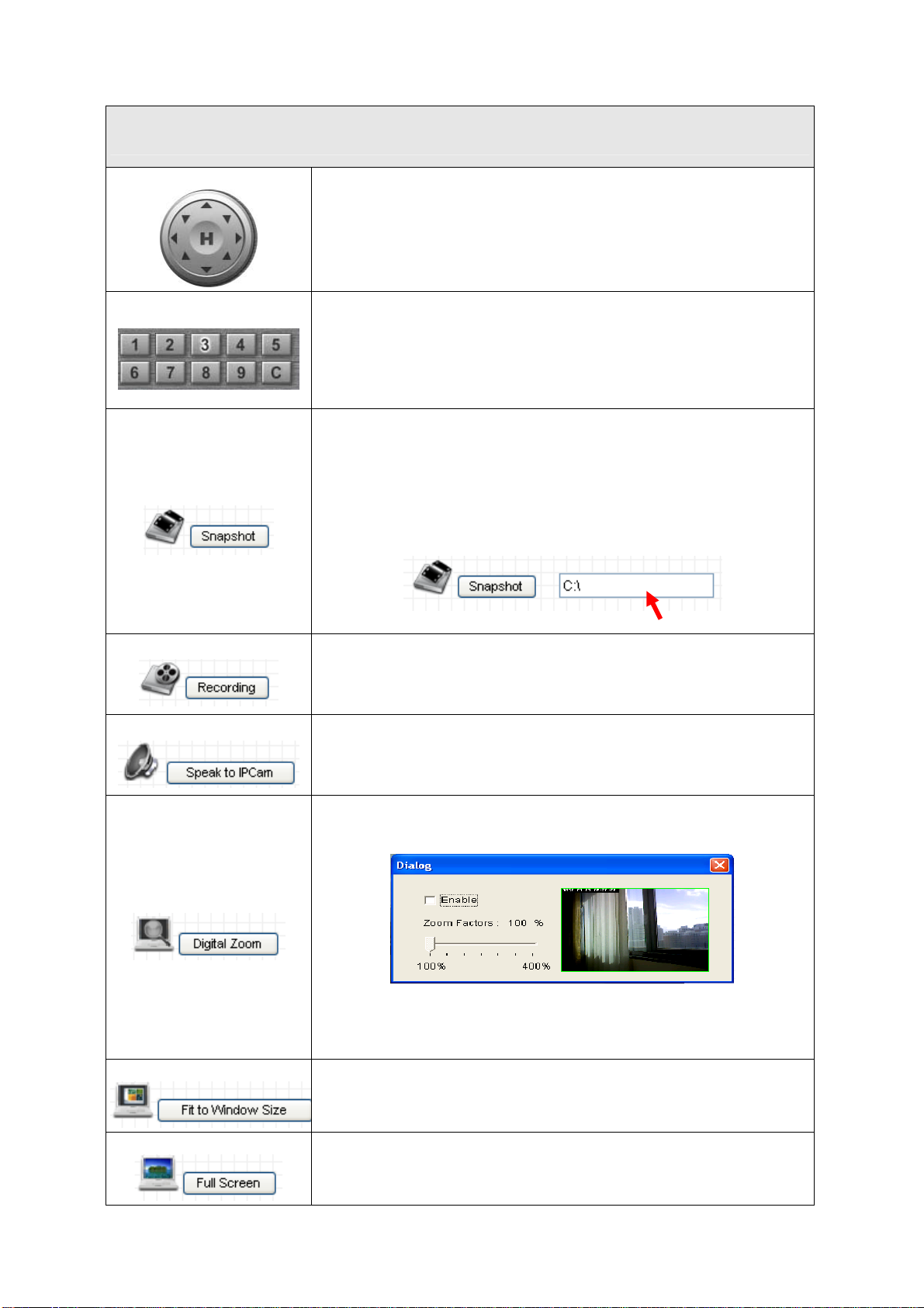
Pan / Tilt Control
Preset Points
Snapshot
Moves camera to a new direction. Press one of 8 directional buttons to
move the camera, and press ‘H’ to move the camera back to ‘home’
(original) position.
You can set up to 9 preset points of camera position; press the number
to move the camera to preset point instantly. See next chapter for detail
instructions of how to set preset points.
Press ‘C’ and the camera will cruise between all preset points
automatically.
Click ‘Snapshot’ button to save the displaying image as an image file, a
message box will appear after you click ‘Snapshot’ button, showing the
filename and location of saved image file (default filename is current
date and time).
Default directory used to save image file is ‘C:\’, you can change the
directory by clicking the text input box located at the right of ‘Snapshot’
button:
and you’ll be prompted to select a new directory.
Recording
Speak to IP Cam
Digital Zoom
Fit to Window Size
Press this button to record the displaying image as a video file in AVI
format, and you can play the video file back by Windows Media Player.
To stop recording, press ‘Stop Recording’ button (the same button). You
can also change the directory used to save video file.
You can transmit the voice received by your computer’s microphone to
the camera’s external speaker. Press and hold this button, then speak to
the microphone. Please note that external speaker must be connected
to this camera.
If you wish to enlarge certain portion of the captured image, you can
click this button to set digital zoom:
Click ‘Enable’ to enable digital zoom function, then you can drag the
slide bar to adjust zoom ratio. You can also use your mouse to drag the
zoom area (the yellow square) to reposition the zoom area.
Click this button and the image size will be adjusted to fit the size of
browser window.
Full Screen
Click this button to display the image in full-screen mode (uses all
available space to display the image captured by this camera).
16
Page 17
2.2 Pan and Tilt
This IP camera supports pan and tilt function, as you explored in last section. You can also make the camera
move automatically in pan and tilt menu by defining a set of pre-defined path.
You can access this menu by clicking ‘PTZ’ on the top of web management interface.
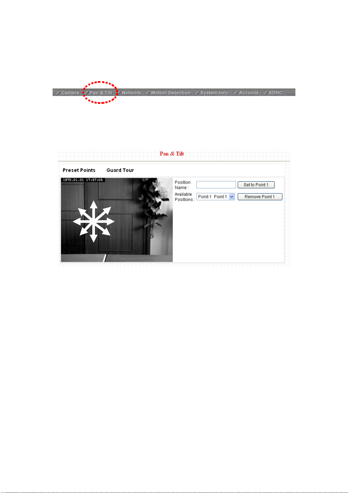
2.2.1 Preset Points
You can define the camera position and save the position so you can recall the position later again. This
camera provides 9 memory slots; follow the following instructions to move the camera and set a new preset
point:
UPPER
LEFT
UP
UPPER
RIGHT
RIGHT LEFT
LOWER
LEFT
LOWER
RIGHT
DOWN
1. Select a memory slot from ‘Available Positions’ dropdown menu first.
2. To move the camera, click the position of labeled text (not shown on image) on the image to move the
camera to the direction. You may need to set the Pan / Tilt speed to a slower setting, so you can move the
camera in a more accurate manner.
3. When you move the camera to the position you want, type a name in ‘Position name’ field, and click ‘Set to
Point n’ (where ‘n’ is the number of memory slot) button to save the position to selected memory slot.
After you set the position, you can recall the position from ‘Camera’ menu (click the position number button),
and the camera will move to preset position instantly.
If you want to remove a preset position, select the memory slot from ‘Available Positions’ dropdown menu,
and then click ‘Remove Point n’, (where ‘n’ is the number of memory slot you wish to clear p osition setting).
17
Page 18

2.2.2 Grand Tour
A
You can make the camera move between many pre-defined positions, and define the time you wish to pause
at every position; this is called as ‘Grand Tour’.
Before you can use this function, you have to define at least 2 positions in ‘Preset Points’ section (refer to last
section for detailed information).
The descriptions of every setting in this menu will be given below:
Item Description
Add
Edit
Add a new set of grand tour (see instructions below)
Edit a selected grand tour. The parameters for an existing grand tour will be
recalled and you can modify them.
Select a grand tour and click this button to start grand tour, click again to stop it.
Start / Stop
fter a grand tour has been started, go to ‘Camera’ menu to see it in action. Only
one grand tour can be activated at the same time.
Remove
Remove a grand tour from the list.
If you wish to add a new set of grand tour, click ‘Add’ to start to add a new grand tour set:
18
Page 19
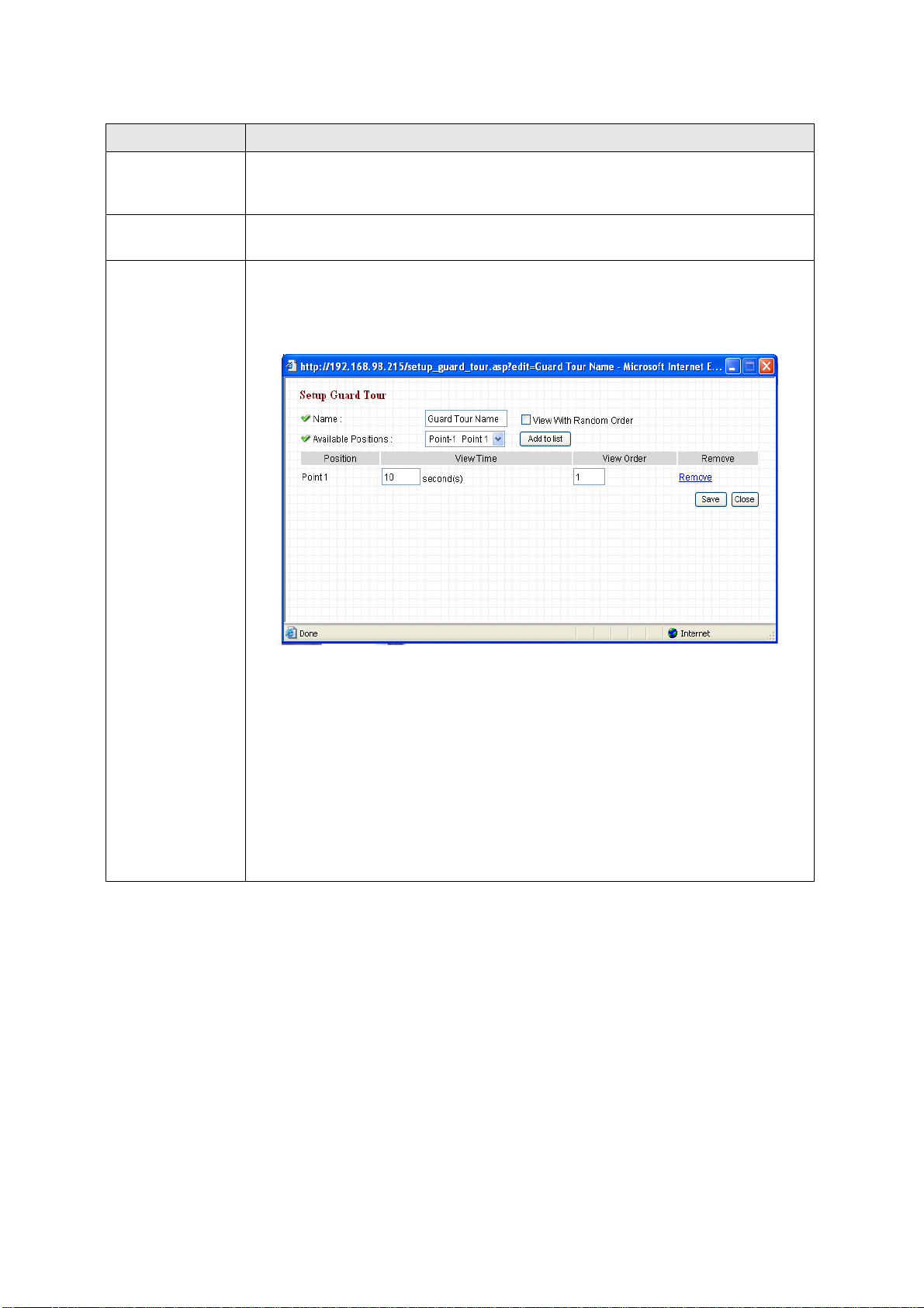
The descriptions of every setting in this menu will be given below:
V
Item Description
Input the name of this set of grand tour here. As you m ay have many set s ofgrand
Name
tour, please give it a meaningful name so you can remember the main purpose of
this set.
iew with random
order
Available
positions
Do not visit all positions in this grand tour by order; visit them randomly instead.
Select preset points from dropdown menu here, then click ‘Add to list’ to add this
position to this grand tour .
When you click ‘Add to list’, you’ll be prompted to set these parameters:
View Time: Define the time you wish the camera to stop at this position in
seconds.
View Order: Give this position a number greater than 1 and not the same with
other positions, and grand tour will start visiting positions b y ord er (from 1 to last
number, and t hen start from 1 again).
Remove: Remove this position from list.
Save: Save settings for this position.
Close: Close this window and discard all changes.
19
Page 20
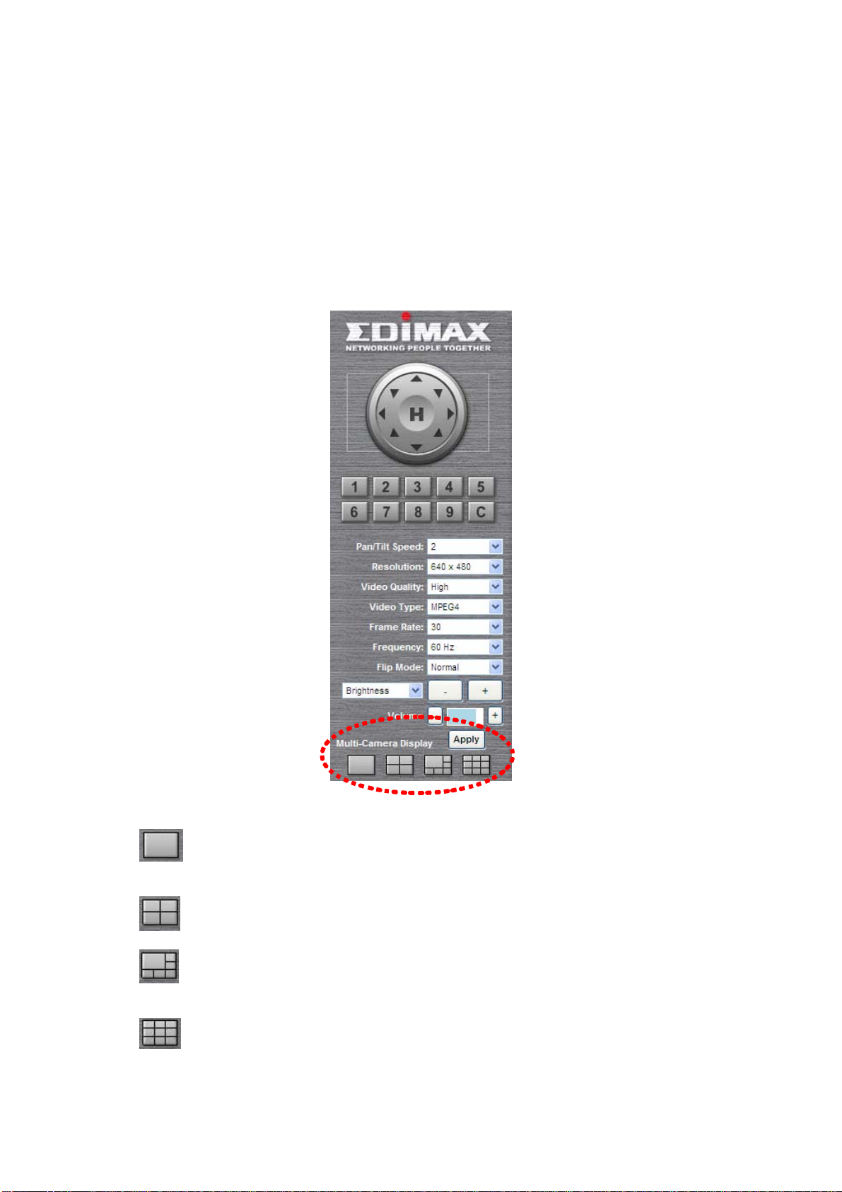
2.2.3 Multi-Camera Display
If you have more than one IC-5010 IP camera, you can view up to 9 videos captured by every camera, so you
can monitor up to 9 places at the same time.
Before you do this, please collect the following information:
a. The IP address of each camera
b. The port (default: 80) of each camera
You can get above information from ‘Network’ menu of each camera, and then you can log onto the web
management interface of any camera, and select one type of multi-camera display:
You can select one type of multi-camera display:
a.
video of the camera you logged onto.
b.
c.
than others.
d.
One-camera view: Only one camera’s video will be displayed, and you can only see the
Four-camera view: You can see the video of up to 4 cameras.
Six-camera view: You can see the video of up to 6 cameras, and one camera’s view is larger
Nine-camera view: You can see the video of up to 9 cameras.
20
Page 21
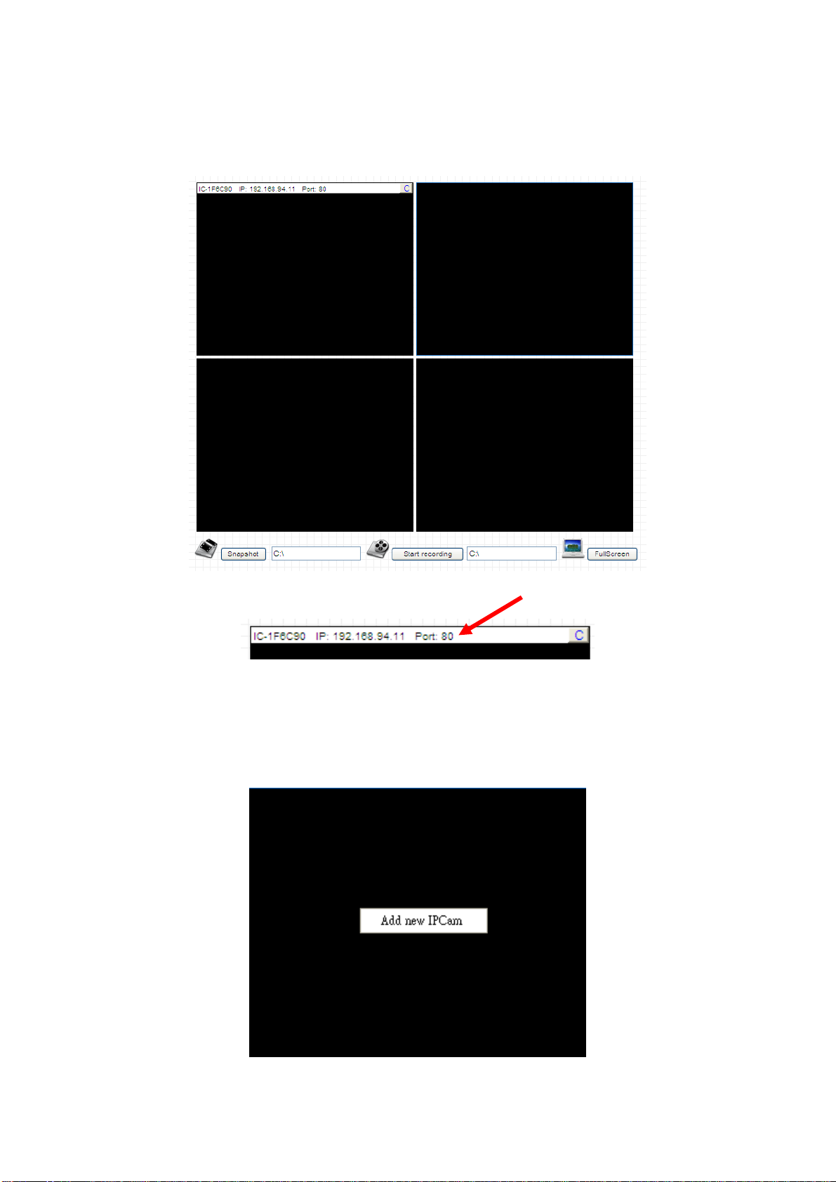
Please note that the upper-left camera view always show the video of the camera you connected to and
cannot be changed.
The following example uses four-camera view as example, and the video of the camera you connected to is
displaying at upper-left view:
The IP address and port will be displayed at the top of camera’s view:
When IP and port information is displayed on the top of camera’s view, indicates the camera is configured.
You can also click the image to point the camera to a new position, as instructed in chapter 2.2.1. To point the
camera to center position, click ‘C’ mark located at up per-right corner.
If you wish to configure new camera for a specific camera view, please right-click on the camera view and
select ‘Add new IPcam’:
21
Page 22

A new popup window will appear to allow you to set the information of camera. If you have popup blocker
installed, you may have to disable it temporarily so you can see the popup window:
Please input the information in respective field (Camera IP, HTTP Port etc.), then click ‘Add new IPCam’
button to connect to this IP camera and display it’s view in camera view. If you don’t want to add the camera
now, click ‘Close’ button and the popup window will be closed.
When a camera is connected, you can also right-click on camera’s video and a sub-menu will appear:
Click ‘Mute’ and you won’t hear the voice capture d by this camera, and you can also click ‘Ab out’ to check the
version information of camera’s ActiveX plug-in:
22
Page 23

2.3 Network Settings
All network-related settings can be found in this menu, and you have to specify TCP/IP parameters in this
menu if you want to change IP address, use PPPoE, Dynamic DNS, and activate UPnP function.
You can access this menu by clicking ‘LAN’ on the top of web management interface.
After you selected ‘Network’, network setting menu will appear. There are 5 sub-menus available here:
Please click the network setting you wish to set, and then refer to instructions given below:
2.3.1 LAN
You can define IP address and select the port number you wish to use here.
23
Page 24

The descriptions of every setting in this menu will be given below:
Item Description
This camera can obtain the IP address from DHCP server automatically (if you
have one), or set a fixed IP address. Select ‘DHCP’ to obtain IP address
Network Type
automatically or ‘Static IP Address’ to assign this IP camera with a fixed IP
address.
When ‘DHCP’ is selected, IP address parameters below will be grayed out.
IP Address
Subnet Mask
Gateway
Primary DNS
Secondary DNS
AV Control Port
Web Port
Enable PPPoE
User Name
Specify the IP address for this IP camera here.
Specify the subnet mask for this IP camera here.
Specify the gateway address of the local network here.
Specify the IP address of DNS server here. Please input IP address only. If you
don’t know the address of DNS server, ask network administrato r or your ISP for
help.
Specify the IP address of backup DNS server here. When primary DNS is
unreachable, IP camera will use the IP addres s specified here as DNS server.
This field is optional.
Specify the port number of video transfe r here. If you have firewall on your
network, you need to allow computers on Internet to access this port number of the
IP address of IP camera, or you’ll not be able to view video from Internet.
Specify the port number of web management interface here. If it’s not 80, you’ll
have to add ‘:port’ after the IP address / hostname of this IP camera.
For example, if the HTTP port number you specified here is 90 and the IP address
of IP camera is 10.20.20.30, then you have to input ‘http://10.20.20.30:90’
in the address bar of Internet explorer.
Select ‘Enable’ to activate PPPoE function of this IP camera, select ‘Disable’ to
disable it.
Input the PPPoE username assigned by your ISP here.
Password
Input the PPPoE password assigned by your ISP here.
Input the MTU (Maximum Transmi ssion Unit) given by your ISP here. Ask your ISP
if you don’t know what value you should input here.
MTU
Default value should work with most of ISPs and will give you a nice network
performance.
Click ‘Apply’ to save settings and make the new settings take effect.
24
Page 25

2.3.2 WLAN
The descriptions of every setting in this menu will be given below:
Item Description
Wireless
Connection
Select ‘Enable’ to activate wireless network function of this IP camera, select
‘Disable’ to disable it.
Select the network type of wireless connection.
Available options are ‘Infrastructure’ (Connect the IP camera to a wireless
access point), and ‘Adhoc’ (This IP camera will become a stand-alone wireless
network point, other wireless computers / devices can discover this IP camera
Network Type
and connect to it without wireless access point).
You can set to ‘Adhoc’ when you don’t have any wireless access point, but your
computer has wireless network card. Set to ‘Infrastructure’ when you have
wireless access point, and you have computers with wired network connection.
Here shows all wireless access points found by this IP camera. Please note not
all access points will be displayed at the same time, if the access point you
expected to connect does not appear, you may have to click ‘Refresh’ button for
several times until it appears.
Available
Networks
The descriptions of all fields is listed below:
Connect: You can select the wireless access point you wish to connect here.
SSID: the SSID of all found wireless access points will be shown here. Some
wireless access point may hide their SSID; in this case, you have to identify
them by their MAC address.
25
Page 26

SSID
Channel
MAC Address: If you there are many wireless access point s in proxi mity or some
wireless access point hides it’s SSID, you can use MAC address to distinguish
them.
Signal: Shows the radio signal strength in percent.
Channel: Shows the radio channel of this wireless access point.
Encryption: Shows the encryption type used by this wireless access point. You
must use the same encryption type if you wish to connect to a certain wireless
access point. If the wireless access point does not use encryption, ‘Disabled’ will
be displayed here.
Network Type: Shows the network type of a certain wireless access point
(Infrastructure or Adhoc).
Input the SSID of the wireless access point you wish to connect. It should be
less than 32 alphanumerical characters.
When you select a wireless access point above, it’s SSID will be filled in this field
automatically. However, if the SSID is not displayed (the wireless access point
you selected choose to hide it’s SSID), you have to know it’s SSID and input it
here, or you will not be able to connect it.
Select the radio channel you wish to use here. When network type is
‘Infrastructure’, the radio channel is auto-selected according to the channel that
wireless access point uses. You can only select the channel number when
network type is ‘Adhoc’.
Wireless Key
Self PinCode
Configure via Push
Button
Configure via
PinCode
Input the encryption key of selected wireless access point here. This is required
when access point you wish to connect uses encryption.
Here displays the WPS pin code used to connect to WPS-enabled wireless
access points. You have to input this number into the WPS enabled access point
to establish WPS connection.
Click this button and this camera will enter PBC-style WPS connection state for
120 seconds. Please push ‘Start PBC’ button on the wireless access point you
wish to connect within 120 seconds to establish WPS connection (The remaining
time will be displayed on the button).
If connection can not be established after 120 seconds, you’ll be prompted by a
message box, and you can press ‘Start PBC’ button to try again.
If you have wireless access point’s WPS PIN code, you can input it here and
press ‘Start PIN’ button to start to establish PIN-style WPS connection.
26
Page 27

2.3.3 Dynamic DNS
If your ISP does not give you a fixed Internet IP address (i.e. the Internet address you’re using when you
access the Internet is not always the same – ask your ISP for detailed information), you can use this function
to help you locate the IP address of this IP camera when you’re away from home or office.
Before you can use this function, you’ll need to apply for an account at dyndns.org (http://www.dyndns.org
).
Detailed instructions of how to apply a new account can be found on dyndns.org’ s website.
The descriptions of every setting in this menu will be given below:
Item Description
Enable DDNS
Provider
Host Name
User Name
Password
Select ‘Enable’ to activate Dynamic DNS function of this IP camera, select
‘Disable’ to disable it.
Select dynamic DNS service provider he re. Only dynd ns.org i s available cu rrently.
Input dynamic DNS host name here.
Input dynamic DNS user name here, must be the same as the one you applied on
dyndns.org.
Input dynamic DNS password here, must be the same as the one you applied on
dyndns.org.
Click ‘Apply’ to save settings and make the new settings take effect.
27
Page 28

2.3.4 UPnP
When UPnP function is activated, all UPnP-compatible computers / network devices will be able to discover
this IP camera automatically (only those in the same local network).
This function is useful and you don’t have to remember the IP address of this IP camera. Sim ply open
‘Network neighbor’ and it’s there!
The descriptions of every setting in this menu will be given below:
Item Description
Enable UPnP
Select ‘Enable’ to activate UPnP functio n of this IP camera, select ‘Disable’ to
disable it.
Click ‘Apply’ to save settings and make the new settings take effect.
After UPnP function is activated, a popup message will appear:
Click the message to open ‘My Network Places’, and you’ll see the IP camera:
Y ou ca n double-clic k the icon to launch Internet Explorer and log onto IP camera’ s web manag ement interface
directly.
28
Page 29

2.3.5 Login Free
This camera provides a method to let unauthorized users to view the image captured by this camera, which is
called as ‘LoginFree’. When you wish to let everyone to view the image captured by this camera, or integrate
the image with your own web application, you can use this function:
Input the filename here, and click ‘Apply’ to save settings, then other users can access the image by this
filename with .jpg extension with the camera’s IP address as prefix. For example, if your camera’s IP address
is ‘192.168.2.1’ and the filename you set here is ‘picture’, then everyone on the web can access the image
captured by this camera by using the following address:
http://192.168.2.1/picture.jpg
Please note that no authentication will be required to see the captured image. If you wish to disable this
function, clear the text in ‘Filename’ field and click ‘Apply.
29
Page 30

2.4 Motion Detection
When you wish to use this camera to monitor the activities, motion detection function will be very useful.
Camera will detect the motion in captured image, and take a snap shot when motion is detected. So you can
use this camera to keep the safety of the belongings you have.
To use motion detection, click the following link from the top of menu:
After you selected ‘Motion Detection’, a sub-menu will appear. There are 5 sub-menus available here:
Detailed descriptions of every setting will be given below.
30
Page 31

2.4.1 Motion Detection
You can use this menu to setup basic motion detection settings:
The descriptions of every setting in this menu will be given below:
Item Description
Enable Motion
Detection
Select ‘Enable’ to enable motion detection, and select ‘Disable’ to disable this
function.
Select the time interval between two motions from dropdown menu. When a
Motion Detection
Interval
motion is detected, camera will not detect any motion again within the time interval
you specified here. Available options are from 0 second (always detect new
motion) to 60 seconds.
Recording Time
Select the duration you wish this camera to record image when a motion is
detected from dropdown menu. Available options are 1, 2, 3, 4, and 5 (seconds).
Select the file type that will be saved when a motion is detected. Select ‘JPEG’ and
Sending File T ype
a still picture in JPEG format will be saved; and select ‘AVI’ to save a motion video
clip.
Select ‘Enable’ to send the saved file to appointed FTP server when a motion is
Send snapshot
file to FTP
detected, select’ Disable’ to disable this function. Y ou have to configure FTP se rver
parameters in ‘FTP Configuration’ menu first, so this function will take effect (see
below).
Select ‘Enable’ to send the saved file to appointed E-mail address when a motion
Send snapshot
file to E-Mail
is detected, select’ Disable’ to disable this function. Y ou have to configure mail
server parameters in ‘FTP Configuratio n’ menu first, so this function will take effect
(see below).
Send snapshot
file to SD Card
Select ‘Enable’ to send the saved file to SD card when a motion is detected, select’
Disable’ to disable this function. You have to insert a working SD card into the SD
slot of this camera first, so this function will take effect.
Click ‘Apply’ to save settings and make the new settings take effect.
31
Page 32
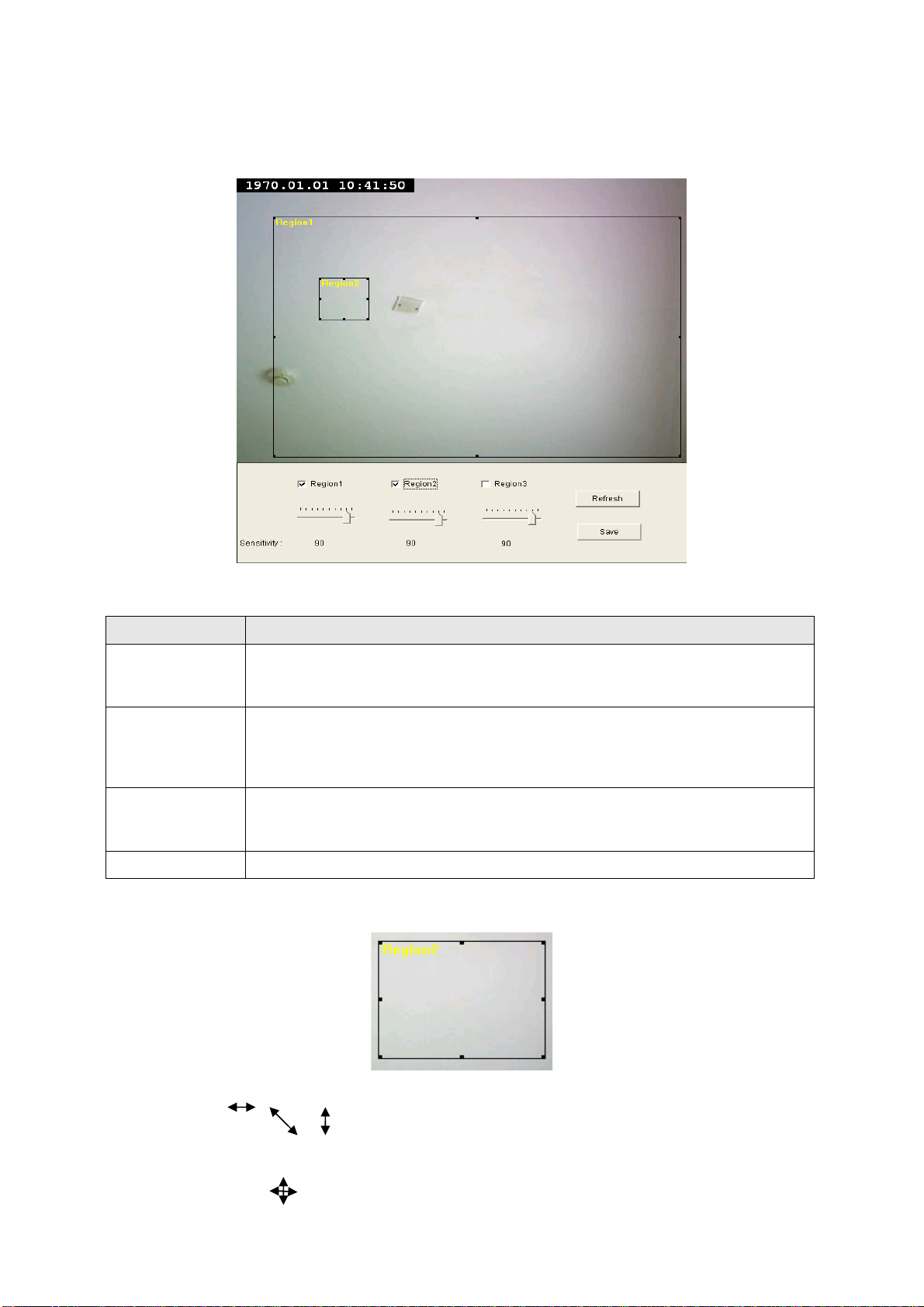
2.4.2 Motion Region
You can define the motion detection region within the image that camera captures, so this camera will ignore
motions which are not covered by the motion region setting, and reduce the chances of false alarm.
The descriptions of every setting in this menu will be given below:
Item Description
Check the box to enable motion detection region 1 to 3. You can check multiple
Region 1 – 3
boxes to enable multiple motion detection regions. When you checked a box, a
new region (and region number) will be displayed on captured image.
Move the slide bar to change the motion detection sensitivity setting: Drag the
Sensitivity
slide to the right to increase sensitivity (camera will detect minor changes in the
image), and drag the slide to the left to decrease sensitivity (camera will only
detect major changes in the image).
In case the objects of the image captured by the camera moved, click this button
Refresh
to reload the image captured by camera, so you can decide the motion detection
region more precisely.
Save
Save motion detection region settings.
To change the motion detection region, you can ‘resize’ and ‘reposition’ it:
Move the mouse cursor to the eight dots located at the border of motion detection region, and the mouse
cursor will switch to , , or . You can click and hold mouse button and move the mouse to resize the
motion detection region.
To move reposition the motion detection region, move the mouse within the motion detection region, and the
mouse cursor will switch to . Click and hold mouse button and move the mouse to reposition the motion
detection region.
32
Page 33
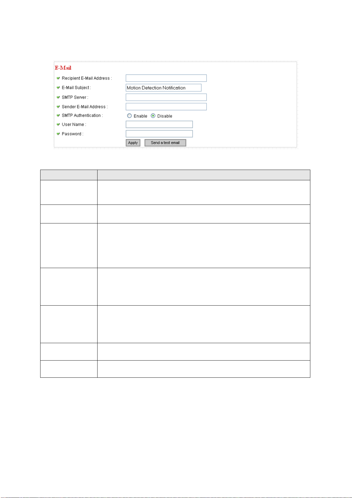
2.4.3 Email
You can define the destination address of E-mail sending and mail server parameters here.
The descriptions of every setting in this menu will be given below:
Item Description
Recipient E-Mail
Input the email recipient’s Email address here.
Address
E-Mail Subject
Specify the title of sending email, so you can identify the mail sent from this
camera from others quickly.
Input the IP address or host name of the SMTP server (the server that delivers
the Email for you) here.
SMTP Server
If you don’t know, please refer to the SMTP server you’re using in your Email
software (like Outlook, Outlook Express etc.), or ask your network administrator
or ISP.
Input the Email address of mail sender, this will help you to identify the Email
Sender E-Mail
Address
sent by this IP camera by sender’s Email address.
NOTE: Some mail server would reject to deliver the Email from unknown sender ,
it’s recommended to input your own Email address here, or any other a ctual one.
Some SMTP server requires mail senders to be authenticated before they can
SMTP
Authentication
send Email. If your SMTP server requires you to do so, please select ‘Enable’, or
select ‘Disable’ to disable it. If you don’t know, please refer to the SMTP server
you’re using in your Email software (like Outlook, Outlook Express etc.), or ask
your network administrator or ISP.
User Name
Password
Please input the user name of SMTP server here, if your SMTP server requires
the use of authentication.
Please input the password of SMTP server here, if your SMTP server requires
the use of authentication.
Click ‘Apply’ to save settings and make the new settings take effect.
After that, you can click ‘Send a test email’ to send a testing Email to the address you set here, so you can
make sure the setting you specified here is correct and working.
33
Page 34
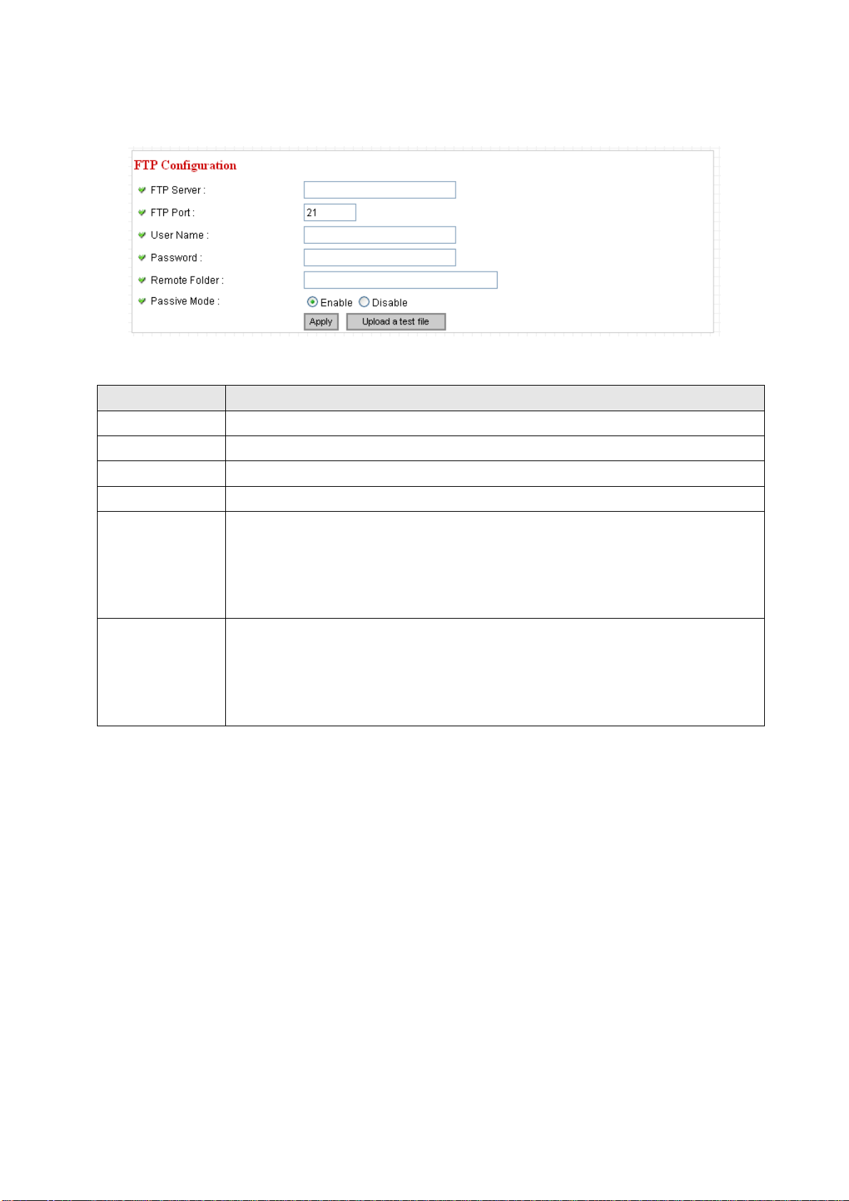
2.4.4 FTP Configuration
You can set FTP server’s parameters here.
The descriptions of every setting in this menu will be given below:
Item Description
FTP Server
FTP Port
User Name
Password
Input the IP address or host name of the FTP server you wish to use here.
Input the port number of the FTP server you wish to use here.
Input the user name of the FTP server you wish to use here.
Input the password of the FTP server you wish to use here.
Input the remote folder name on the FTP server here. If nothing is specified here, all
uploaded image files will be placed in FTP server’s root directory.
Remote Folder
Please ask FTP server’s administrator to know which folder you should use. Certain
user name may have restrictions and therefore can not place the file in the directory
not owned by the user.
Select ‘Enable’ to use passive mode to send file, or select ‘Disable’ to not to use
passive mode to send file.
Passive Mode
Some FTP servers require passive mod e, if you don’t know, please ask FTP server’s
administrator; most of FTP servers will work fine with both modes, but if you found
that non-passive mode is not working, you can try to use passive mode.
Click ‘Apply’ to save settings and make the new settings take effect.
After that, you can click ‘Upload a test file’ to send a file to the FTP server you set here, so you can make sure
the setting you specified here is correct and working.
34
Page 35
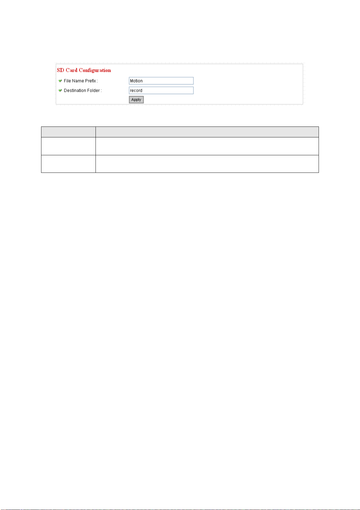
2.4.5 SD Card Configuration
You can define the filename and destination folder when saving a file in SD card.
The descriptions of every setting in this menu will be given below:
Item Description
File Name Prefix
Destination
Specify the filename prefix (the texts whi ch will b e added before the file sequence
number).
Specify the folder name that camera will store the saved image or video clip.
Folder
Click ‘Apply’ to save settings and make the new settings take effect.
35
Page 36

2.5 System Info
You can use this menu to get the operational information of this camera:
…
After you selected ‘System Info.’, a sub-menu will appear. There are 4 sub-menus available here:
Detailed descriptions of every setting will be given below.
2.5.1 Camera Information
Camera information allows you to set the name and administrator’s password of this camera.
The descriptions of every setting in this menu will be given below:
Item Description
Please specify the name of this IP Camera here. This can be used to identify
your camera on the network when you have more than one IP camera in the
same network.
Camera Name
Default name begins with ‘IC-‘ plus the last 6 characters of the MAC address of
this IP camera. You can modify the name to the one you can remember and
meaningful to you, but never give all IP cameras in the same network with same
name.
Password
Confirm Password
Click ‘Apply’ to save settings and make the new settings take effect.
Please specify user name ‘admin’ ‘s password here. (The one you need when
you log onto web management interface and use ‘admin’ as user name.
Please input the same password again, to make sure there’s no typo.
36
Page 37

2.5.2 Date / Time Setting
This setting allows you to change the date and time of the real time clock in this IP camera. You can set the
time manually, or use network time protocol (NTP) to set the time automatically.
The descriptions of every setting in this menu will be given below:
Item Description
If you select ‘Set Date/Time manually’, you can set the date and time of this
camera manually. Please input the date and time you wish to set here.
Date / time format is YYYY / MM / DD HH:MM:SS
Time is in 24-hour format.
Set Date/Time
manually / NTP
Server
You can click ‘Synchronize to PC time’ to use the time of the computer you’re
using.
Example: 24
th
August 2007 = 2007/ 08 / 24,
and PM 9:24:30 = 21:24:30
If you select ‘NTP Server’, the camera will get the date and time from NTP Server
automatically.
Time Zone
Please select the time zone of the country / city of resident from dropdown menu
here.
Please input the IP address or host name of NTP server here. You can use default
NTP Server
value ‘pool.ntp.org’, or ask your ISP for the IP address or host name, if they have
one.
Click ‘Apply’ to save settings and make the new settings take effect.
If you wish to use the date and time setting of the computer which is connecting to the camera, click
‘Synchronize to PC time’ button. The date and time setting of the computer will be filled to date and time
setting in this page.
37
Page 38

2.5.3 Utilities
This menu allows you to upgrade firmware, clear all settings, reboot the IP camera, and switch LED lights
on/off.
The descriptions of every setting in this menu will be given below:
Item Description
If you downloaded latest firmware file from our website, you can click ’Browse’
button to pick a firmware file located on your computer’s hard drive and you can
upload the firmware file to the IP camera later.
After you selected a proper firmware file from your computer, click ‘Upgrade
Upgrade
Firmware
Firmware’ button to start upgrade. DO NOT DISCONNECT NOW!
If the firmware file you provided is invalid of you didn’t provide the firmware file,
you’ll be prompted to select another valid firmware file again.
The IP camera will reboot after the upgrade procedure is done. PLEASE NOTE
THA T THE IP ADDRESS OF THE CAMERA WILL RESET TO DEFAULT VALUE:
192.168.1.61
Clear all settings in the camera. Please think again before you do this, and then
click this button to reset all settings.
Reset to Factory
Defaults
NOTE: IP address will be reset to default value ‘192.1 68.2.3’ also. You’ ll need to
change the IP address setti ng of your computer if the IP address of you r computer
does not begin with ‘192.168.2’, and subnet mask is not ‘255.255.255.0’, or you’ll
not be able to connect to this IP camera again.
Reboot Device
If you found the IP camera is responding slowly or behaves strange, you can click
this button to try to reboot the IP camera, this may help.
Click ‘Turn off LED light’ button to switch the LED light of this IP camera off, so all
LEDs on the IP camera will stop working, in case you don’t want other people
LED Setting
know the camera is transferring data.
You can click this button again to switch LED lights on again.
Click ‘Apply’ to save settings and make the new settings take effect.
38
Page 39
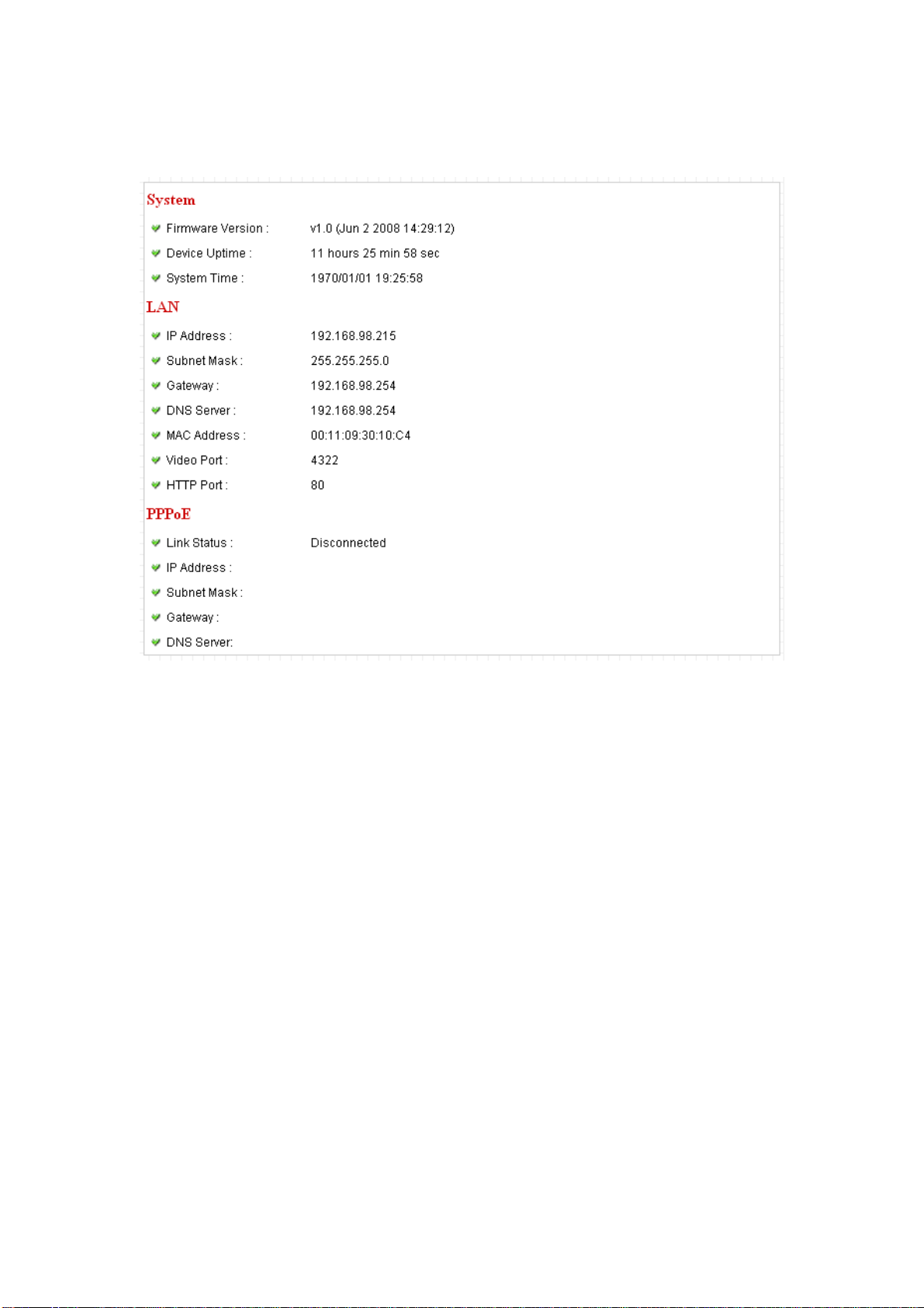
2.5.4 Status
This menu provides all information about this IP camera, like firmware version, system uptime, date / time,
and network information.
39
Page 40

2.6 Account
If you wish to allow other people to view the live image captured by this camera, but don’t want to allow them
to modify system settings, you can give them user-level user name and password, so they can only view the
image and can not change any system setting. When they want to click menus other than ‘Camera’, they will
see the following message informing that they don’t have permission to do that:
This camera supports up to 4** users.
After you selected ‘Account’, you’ll be prompted to input user account information:
The descriptions of every setting in this menu will be given below:
Item Description
Login
Input the login name (user name) of this account.
Password
Confirm password
Add
Input the password of this user here.
Input the password of this user here again for confirmation.
Click this button to add the account.
40
Page 41

When a user is added, it will be listed:
The descriptions of every setting in this menu will be given below:
Item Description
Enable or disable this user account. If you just want to remove the access
privilege of certain account and will give the privilege back later, you don’t have
Yes / No
to delete it, you can set to ‘No’ for this account when you want to remove the
privilege temporarily, and set to ‘Yes’ for this user when you want to give the
privilege back.
Update
Delete
Update the account’s user name and password. You can input the user name
and password for this account again, and click ‘Add’ to change its setting.
Delete this account. Please note that account will be detected right away when
you click this button, so think again before you do it.
Click ‘Apply’ to save settings and make the new settings take effect.
Please note: only one user (including administrator) will be able to view the image of IP camera at the same
time.
41
Page 42

2.7 SDHC
…
After you selected ‘System Info.’, a sub-menu will appear. There are 4 sub-menus available here:
Please click the SD card setting you wish to set, then refer to instructions given below:
2.7.1 Status
Here shows the remaining card space for you.
42
Page 43
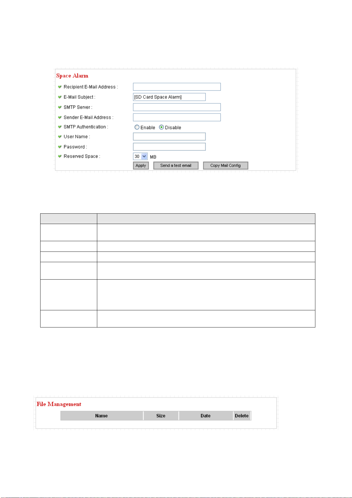
2.7.2 Space Alarm
When you’re using SD card to store captured image and video clip, you can have this camera to sen d an
E-mail to you when there’s only little remaining space left on SD card.
Please note: If you have set E-mail settings in ‘Motion Picture’ function, you can click ‘Copy Mail Config’
button to use the same setting. However, you can use a different setting here.
The descriptions of every setting in this menu will be given below:
Item Description
Recipient E-Mail
Input the E-mail address you wish to receive space alarm.
Address
E-Mail Subject
SMTP Server
Sender E-Mail
Input the title of space alarm E-mail.
Input the SMTP server address you wish to use to send E-mail.
Input the sender E-mail address of the space alarm E-mail.
Address
Select ‘Enable’ if the SMTP serve r you’re using requires authentication, and input
SMTP
Authentication
the username and password below; If the SMTP server you’re using does not
require authentication, select ‘Disable’ here. If you’re not sure, ask your ISP or
network administrator.
Reserved Space
Select the amount of SD card space which will be reserved and will not be used
from dropdown menu.
Click ‘Apply’ to save settings and make the new settings take effect.
You can click ‘Send a test email’ button to send a test E-Mail by the configuration you set here.
2.7.3 File Management
You can use this menu to manage the files stored on SD card.
43
Page 44

Chapter III: Using Surveillance Software
3-1 Installing IP Camera Surveillance Software
The IP camera surveillance software provides various functions like video recording, af ter this software is
installed, you can use your IP camera to safeguard your property. Please follow the following instructions to
install the surveillance software.
1. Double click the setup file located in ‘xxx’ folder in supplied CD-ROM, when the following window appears,
click ‘Next’.
2. You can specify the destination folder of software installation, you can just use the default folder, and click
‘Next’ to continue.
44
Page 45

3. If you need installation program to create a desktop icon or a quick launch icon for you, click all items you
need here, than click ‘Next’ to continue.
4. Here lists all options you chose in previous steps, if everything’s correct, click ‘Install’ to start installing
procedure, or click ‘Back’ to go back to previous step to modify installing settings.
45
Page 46

6. The installing procedure will take some time, please be patient.
6. When you see this window, it means the software installing procedure is complete. Please click ‘Finish’ to
finish the procedure (IP camera surveillance software will start after you click ‘Finish’ button, if you want to
start it later, uncheck ‘Launch IPCam Surveillance Software’ box).
46
Page 47

3-2 Using IP camera surveillance software
You can click ‘IPCam Surveillance Software’ icon from desktop, quick launch bar, or start menu to start the IP
camera surveillance software.
Here are descriptions for all components of IP camera surveillance software:
Before you start:
IP camera surveillance software will only work when your monitor’s
resolution is ‘1024 x 768’. Please change the resolution before you
use IP camera surveillance software, or it won’t start.
Video displaying area
Language
Display
layout
Full screen /
Scan
Zoom Out /
Zoom In
PTZ Control /
Close window (stop
surveillance) /
Minimize window
You can put the mouse cursor on a certain component and see its button name, and here’re detailed
descriptions of all buttons:
Item Description
Message display
box
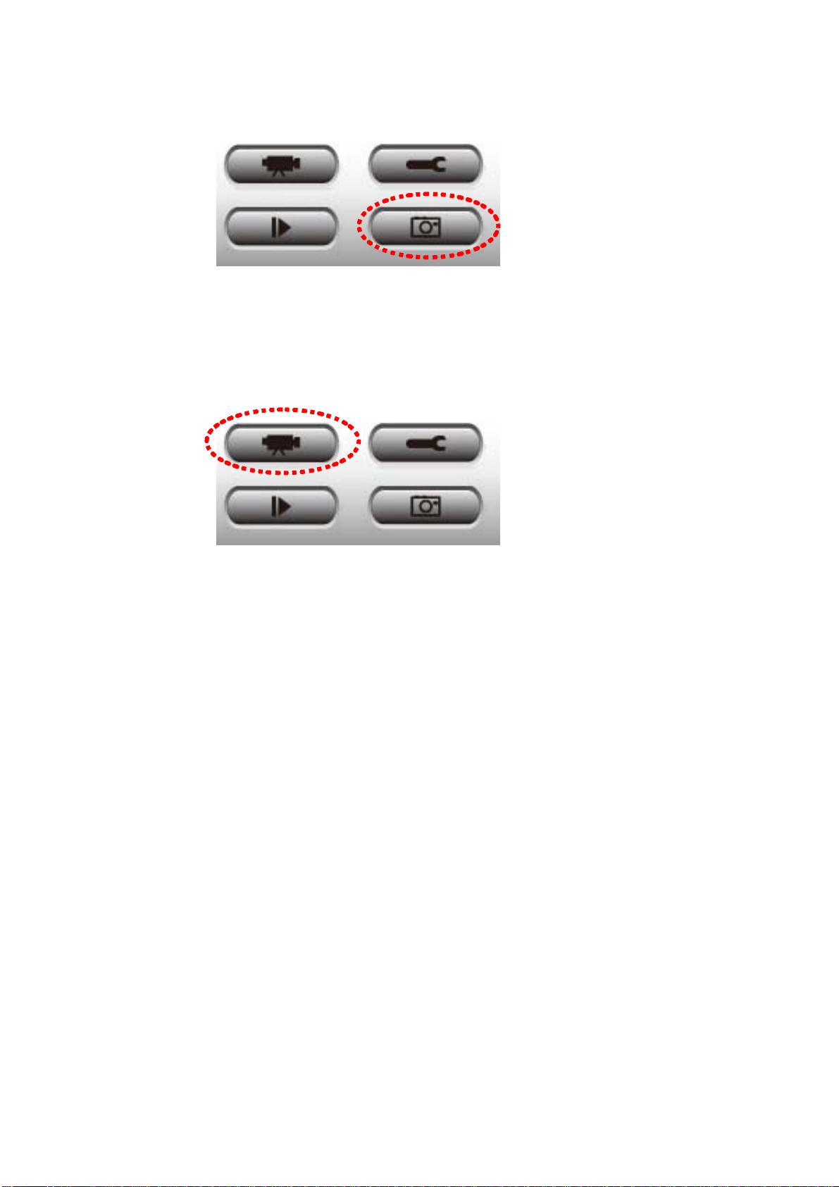
Recording / System
configure
Playback / Snap shot
Home
Video displaying area The image of all connected cameras will be displayed here.
Language Select a language from this dropdown menu to change display language.
Display layout
Change camera image display layout (Click a layout icon to change camera
display layout). There are 8 kinds of available display layouts.
47
Page 48

Full screen
Scan
Click this button to switch to full screen mode (only display all camera’s image),
press ‘ESC’ key to quit full screen mode.
Click this button and the IP camera surveillance software will switch displaying
the image of all connected camera automatically. Click this button once to
activate scan function (scan icon will become blue
scanning (scan icon will become white
).
), click again to stop
Zoom out
Zoom In
PTZ control
Home
Recording
Configure
Playback
Zoom-out (To see more objects).
This function is only available for supported cameras.
Zoom-in (Too see more details).
This function is only available for supported cameras.
There are 8 directions in PTZ control ring. If the camera you connect support
PTZ, you can use PTZ control ring to change the direction that camera points
to.
This function is only available for supported cameras.
Click this button to return the camera to ‘Home’ (default) position.
This function is only available for supported cameras.
Start video recording.
Software / camera configuration.
Playback a recorded video file.
Snapshot
Take a snapshot of current camera.
Message display Displays all system messages like camera is disconnected etc.
Close window
Terminates IP camera surveillance software.
(stop surveillance)
Minimize window
Minimizes IP camera surveillance software window.
Video displaying area Displays the image of all cameras by the display layout you selected.
48
Page 49

3-3 Configure IP camera surveillance software
3-3-1 Configure cameras
Before you use this IP camera surveillance software, you must configure the camera(s) you wish to connect.
Please click ‘System configure’ button
and a popup menu will appear:
Please select ‘Configure Cameras’ to configure cameras:
Note: If you’re prompted by a windows security alert which asks you if
you want to block ‘IPCam Viewer’ program, please click ‘Unblock’
button, of IP camera surveillance software will not be able to function
correctly.
49
Page 50
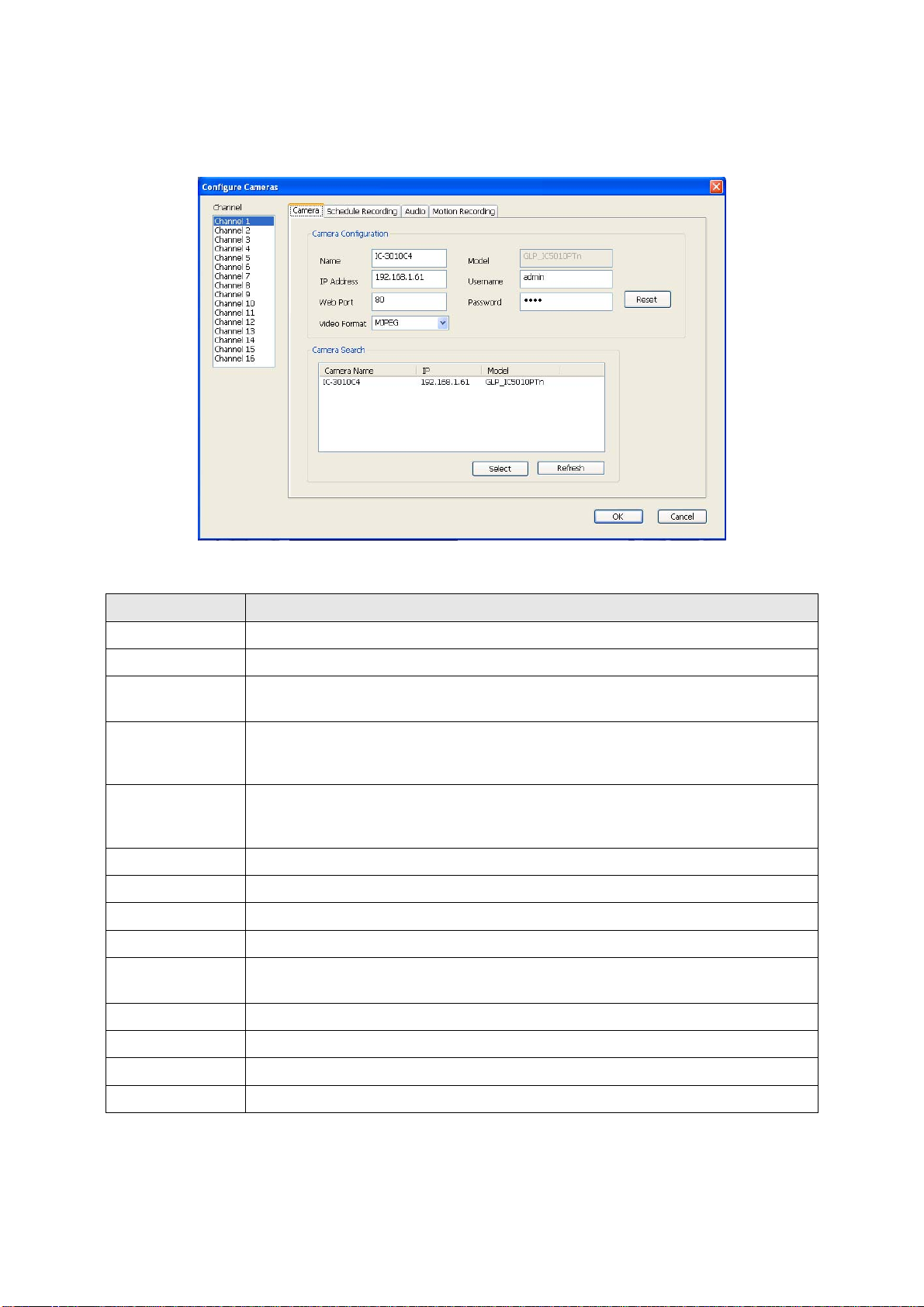
3-3-1-1 ‘Camera’ tab
In this tab you can configure all cameras you wish to connect. Up to 16 cameras can be connected
simultaneously:
Here are the descriptions of all setting items:
Item Description
Channel
Camera Search
Select
Select the channel number you wish to set.
All cameras found on your local network will be displayed in ‘Camera Search’ box.
Select a camera listed in ‘Camera Search’ box, and click ‘Select’ button to fill all
parameters of selected camera in every camera configuration fields.
Rescan all cameras on your local network. If you didn’t see the camera you
Refresh
expected in ‘Camera Search’ box, or new cameras has been joined to your local
network after last scan.
Input the name of camera here. Default value is the first 6 bytes of camera’s MAC
Name*
address, you can change the name of camera so you can remember the camera’s
location of purpose easily.
Model
IP*
Username*
Web Port*
Password
Displays the model of selected camera, this field can not be changed.
Input the IP address of camera.
Input the user name of camera.
Input the web port of the camera. By default it’s ‘80’.
Input the password of camera. Default value is ‘1234’. You should change the
password if you changed the password of selected camera.
Video Format**
Reset
OK
Cancel
Select the video encoding format of this camera (MJPEG or MPEG4).
Clear all fields in ‘Camera Configuration’ section.
Save settings in this tab.
Discard all settings in this tab.
*: It’s recommended to use ‘Select’ button to fill the content of this field.
**: Only available for cameras support this function.
50
Page 51

After you’ve set all channels you wish to set, click ‘OK’ to save settings, and if everything’s correct, you’ll see
the camera’s image in IP camera surveillance software’s main menu:
3-3-1-2 Schedule Recording
In this tab, you can setup scheduled video recording, so you can record the vide o captured by all cam eras you
have by a pre-defined schedule.
51
Page 52

Here are the descriptions of all setting items:
Item Description
Channel
One Time Schedules
New
(One Time Schedules)
Edit
Select the channel number you wish to set.
You can specify the one-time schedule for selected camera; this schedule
will be executed once only.
Click this button and a new window will appear:
Please specify the time duration of this one-time schedule (the date and
time of ‘From’ and ‘To’), then click ‘OK’ to save settings.
Please note you must set a schedule that will be happened in the future,
you can not set a schedule in the past.
You can modify a scheduled recording item. Select a schedule in ‘One Time
Schedules’ list, and click ‘Edit’ button to edit the start and end time of this
schedule.
Delete
New
(Weekly Schedules)
Edit
Delete a selected schedule item.
Click this button and a new window will appear:
You can define recording schedule that will be executed at the specified
time of certain weekday(s) in a week. Please check all weekdays that
applies, and set the start time in ‘From’ field. You can set the duration of
video recording in ‘Period’ field (format is HH:MM:SS), and the end time will
be calculated automatically and displayed in ‘To’ field. You can also click ‘All
Time Record’ button to define a recording schedule that will be executed
every weekday, from 12:00:00AM to 11:59:59PM.
Click ‘OK’ to save chan ges.
You can modify a scheduled recording item. Select a schedule in ‘One Time
Schedules’ list, and click ‘Edit’ button to edit the start and end time of this
schedule.
Delete
OK
Cancel
Delete a selected schedule item.
Save settings in this tab.
Discard all settings in this tab.
52
Page 53

3-3-1-3 Audio
For cameras that support audio, you can use this tab to decide if you wish to hear the audio captured by
selected camera.
Here are the descriptions of all setting items:
Item Description
Channel
Mute Audio
Record Video Only
OK
Cancel
Select the channel number you wish to set.
Check this box and the IP camera surveillance soft ware will not play the audio
captured by this camera.
Check this box and the IP camera surveillance software will not record the
audio captured by this camera.
Save settings in this tab.
Discard all settings in this tab.
53
Page 54

3-3-1-4 Motion Record
With this function activated, only motions captured by the camera will be recorded, so you don’t have to waste
hard disk storage space on images you don’t need to pay attention to.
WARNING: For applications that security is highly concerned, it’s not
recommended to use this function since some tiny changes you may need
to know may not be able to trigger the camera and the camera will not start
recording.
Here are the descriptions of all setting items:
Item Description
Channel
Enable
Disable
Recording Time
Invoke alarm when
motion is triggered
Send mail when
motion is triggered
OK
Cancel
Select the channel number you wish to set.
Enable motion record function.
Disable motion record function.
Select the time duration that camera will record when a motion has been
detected from dropdown menu in seconds.
Send an alarm when a motion has been detected by the camera.
Send an email to a pre-defined address when a motion has been detected
by the camera.
Save settings in this tab.
Discard all settings in this tab.
54
Page 55
3-3-2 General Settings
You can set system-wide settings of this IP camera surveillance software in this menu.
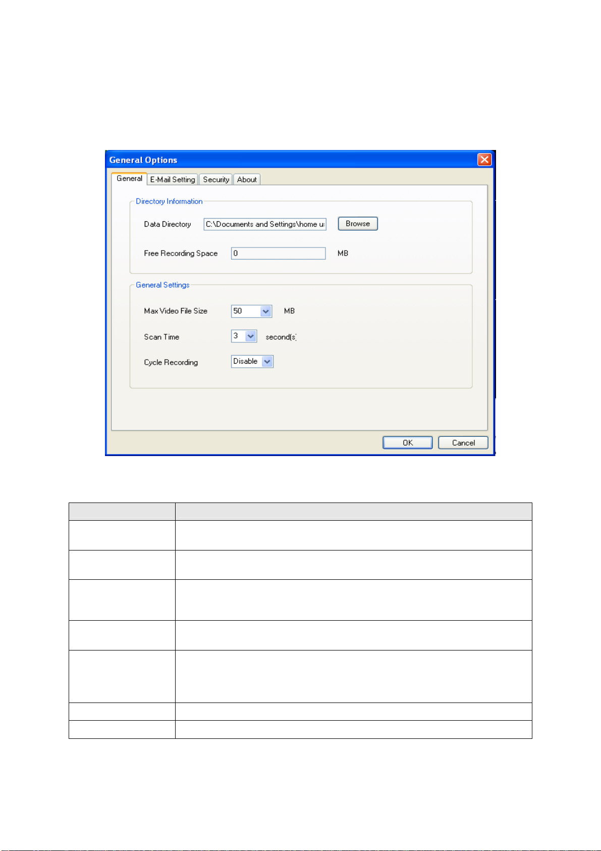
3-3-2-1 ‘General’ tab
All general settings like file storage directory and recording spaces can be set here.
Here are the descriptions of all setting items:
Item Description
Data Directory
Free Recording
Set the directory (folder) you wish to store the recorded video and captured
image. You can click ‘Browse’ button to pick a directory in your hard disk.
Displays remaining storage space.
Space
Defines the maximum file size of every video file. When the size of file exceeds
Max Video File Size
this value, IP camera surveillance software will open another file to record the
video.
Scan Time
Define the time period to pause between every camera switch when you
activate ‘Scan’ function.
You can decide the behavior when hard disk space is full:
Cycle Recording
Disable: Do not overwrite recorded video files.
Enable: Overwrite recorded video files.
OK
Cancel
Save settings in this tab.
Discard all settings in this tab.
55
Page 56

3-3-2-2 ‘E-Mail Setting’ tab
If you want to use motion detection function and wish to get an email that contains the image captured by the
camera, please setup your email related parameters here first.
Here are the descriptions of all setting items:
Item Description
E-Mail Subject
Recipient E-Mail
Specify the subject of sending email.
Here lists all email addresses you set.
Address
Click this button and you’ll be prompted to input the email address. Click ‘OK’ to
save changes.
New
Edit
Delete
Select an email address from ‘Recipient E-Mail Address’ box, and click ‘Edit’ to edit
the email address.
Delete selected email address.
Sender E-Mail
Address
SMTP Server
Specify the email address of email sender.
Specify the IP addre ss or host name of the SMTP server you wish to use. For mo st
of ISPs they will only allow its subscriber to use their SMTP server, if you don’t
know which SMTP server you should use, please refer to the setting of your email
software or ask your ISP / network administrator.
56
Page 57

SMTP port
SMTP Auth
SMTP Account
SMTP Password
Specify the port number of the SMTP server you wish to use here. By default (and
the setting of most of SMTP servers) it’s ‘25’.
Select ‘Enable’ if your SMTP serve r req uires authentication, select ‘Disable’ if it’s
not required. If you don’t know if your SMTP server requires authentication, please
refer to the setting of your email software or ask your ISP / network administrator.
Input the SMTP account (username) of your SMTP server here. In most cases, it’s
the same with your POP3 username (the one you used to receive email). Please
refer to the setting of your email software or ask your ISP / network administrator if
you’re not sure about this.
Input the SMTP password of your SMTP server here. In most cases, it’s the same
with your POP3 password (the one you used to receive email). Please refer to the
setting of your email software or ask your ISP / network administrator if you’re not
sure about this.
OK
Cancel
Save settings in this tab.
Discard all settings in this tab.
57
Page 58

3-3-2-3 Security
If you don’t want other people to access this IP camera surveillance software, you can set a password to
protect it.
You’ll need to input the password every time you wish to use this IP camera surveillance software:
To set password, please use ‘Security’ tab in ‘General Options’ menu:
Here are the descriptions of all setting items:
Item Description
Enable
Disable
Password
Confirm Password
Requires password authentication when this soft ware starts.
Password authentication is not required when this software starts.
Input the password you wish to use here.
Input the password you wish to use here again.
58
Page 59
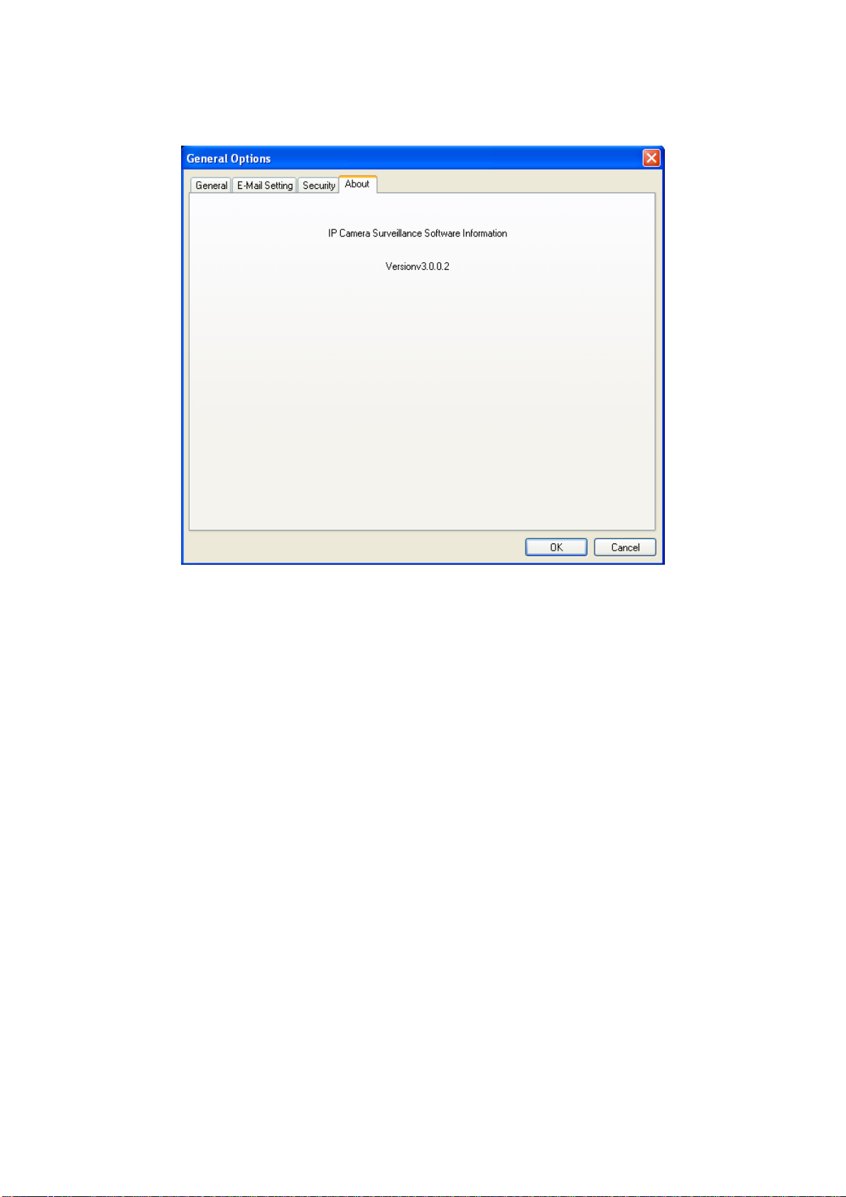
3-3-2-4 About
This tab shows the version number of the IP camera surveillance software you’re usi ng.
59
Page 60

3-4 Change Display Layout
This IP camera surveillance software provides 8 kinds of display layout:
Every layout displays different number of camera and camera arrangement, you can click the icon that
presents a specific kind of layout, and the video displaying area will cha nge accordingly.
Displays the video of 1 camera only.
Layout style 1: 1
Camera only
Displays the video of up to 4 cameras.
Layout style 2: 4
Cameras
Layout style 3: 6
Cameras
Displays the video of up to 6 cameras.
60
Page 61

Displays the video of up to 8 cameras.
Layout style 4: 8
Cameras
Layout style 5: 9
Cameras
Layout style 6: 10
Cameras
Displays the video of up to 9 cameras.
Displays the video of up to 10 cameras.
Layout style 7: 13
Cameras
Layout style 8: 16
Cameras
Displays the video of up to 13 cameras.
Displays the video of up to 16 cameras.
61
Page 62

3-5 Full-screen modes
If you want to use all available spaces on your monitor to display surveillance image, you can click ‘Full
Screen’ button to switch display mode to full-screen mode.
To exit full-screen mode, press ‘ESC’ key.
62
Page 63

3-6 Scan
If you have more than one camera configured, and you wish to switch the displaying image between camera s,
you can click ‘Scan’ button to switch between all configured cameras.
NOTE: If a camera is configured but disconnected, it will still be displayed in a
scan sequence (you’ll see nothing and you’ll see ‘Disconnected’ text
displayed at the upper-left corner of display image).
Click ‘Scan’ button once to activate scan function (scan icon will become blue
scanning (scan icon will become white
).
63
), click again to stop
Page 64
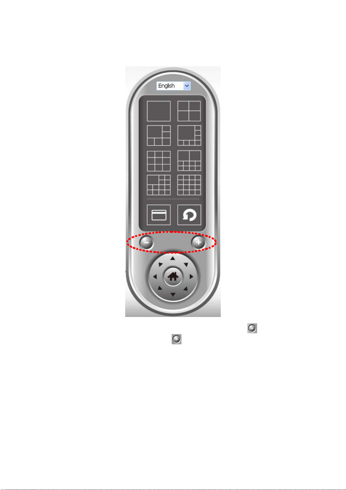
3-7 Zoom-in / Zoom-out
For cameras that support zoom-in / zoom-out function, you can use this function to see more objects that fall
in the scope of camera’s view, or enlarge the image size of a certain object to see its detail.
Please select a camera in video displaying area by clicking on its image, then click
objects that fall in the scope of camera’s view, or click
its detail (Before zoom-in, you may need to use PTZ buttons - described in next section) to find an object you
wish to see its detail).
to enlarge the image size of a certain object to see
64
button to see more
Page 65

3-8 PTZ
For cameras that support pan - tilt function, you can change the position that ca mera point s to, to see dif ferent
places that fall in the scope of camera’s view.
Please select a camera in video displaying area by clicking on its image, and th en click the directions you
wish the camera to move to (total 8 directions available). Click ‘Home’ button (
(default) position.
65
) to return to camera’s ho
me
Page 66
3-9 Snapshot
You can take a snapshot of selected camera and save it to ‘Snapshot’ sub-folde r of pre-defined dat a dire ctory.
Click snapshot button once to take a snapshot; you can take as much snapshot as you want before hard disk
is full.
3-10 Recording
You can start video recording of selected camera manually by clicking ‘Start Recording’ button:
When recording starts, you’ll see a message di splayed in message displaying box like ‘1/1 10:00:00, Camera
2 Start Manual’, which means camera 1 starts recordi ng manually on 1/1 at 10:00:00.
To stop recording, click ‘Start Re cording’ button again, and you’ll see a message displayed in message
displaying box like ‘1/1 10:00:00, Camera 2 St op Manual’.
66
Page 67
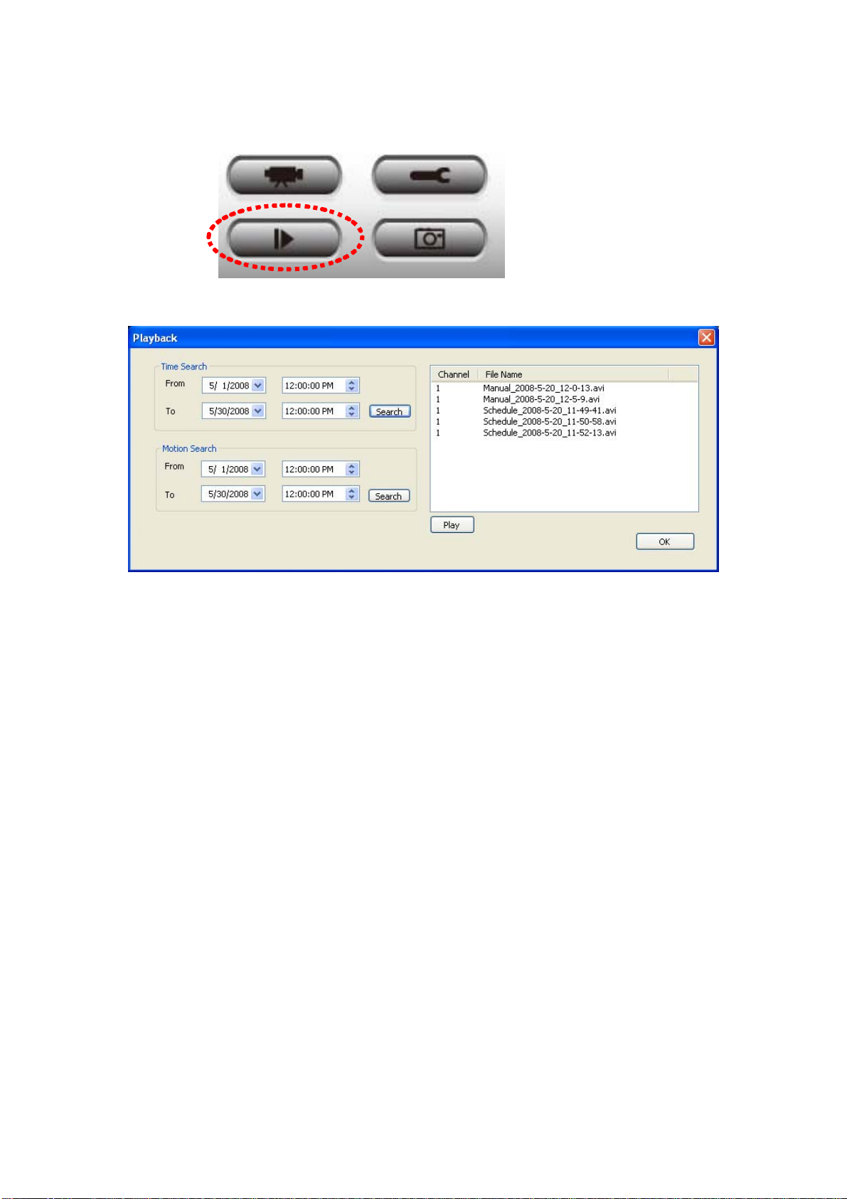
3-11 Video Playback
You can playback all recorded video by clicking this button.
A new window will appear:
You have to search the video file before you can play it. There are two kinds of video search: Time Search
(search all videos file that falls in a specific period of time) and Motion Search (search all videos recorded by
motion detection function and falls in a specific period of time).
Please define the start and end date / time of the time period you wish to search, and then click ‘Search’
button (of ‘Time Search’ of ‘Motion’ Search’). All found videos will be displayed, select the video you wish to
play and click ‘Play’ button to playback.
67
Page 68

Chapter IV: Appendix
4.1 Specification
Max Resolution: 640 x 480 pixels
Sensor: 300K pixels 1/4" color CMOS sensor
Gain control: Automatic
Exposure: Automatic
White Balance: Automatic
Focal Length: 4.8 mm
Aperture: F=1.8
Image (Video Setting)
Image compression: MJPEG Image Video
Digital 24-bit Color
Frame rate: 30fps@QVGA, 20fps@VGA
Video resolution: 176 x 144, 320x240, 640x480
System Hardware
LAN Connector: One RJ-45 port to connect to 10/100Mbps Ethernet
Wireless: IEEE 802.11b/g (*Wireless Model Only)
LED Indicator: LAN LED (Green), WLAN LED (Amber), Power LED (Blue)
HTTP/Utility
Includes easy-to-use Viewer & Recorder utility
Provides Admin utility & WEB browser Management
View multiple cameras simultaneously - Up to 4 cameras at a time
Manual/Schedule Record, Video Playback/Stop/Forward/Pause
Supports four additional user accounts for viewing camera
Auto sending Snap Shot by E-mail or FTP
Support DDNS and UPnP functions
Supports Windows 2000/XP/Vista
Firmware Upgradeable
EMI & Safety
FCC, CE
68
Page 69

4.2 Troubleshooting
If the IP camera is not working properly, before you contact the dealer of purchase for help, please check the
troubleshooting list here, this may help you to solve the problem by yourself and therefore saves your
valuable time.
Scenario Possible Solution
a. Please confirm the IP address setting of the computer you’re using. If they’re
not in the same subnet, they will not be able to communicate with each other.
b. Please make the IP address you used to connect to the IP camera is correct.
c. If you forget the IP address of the IP camera, you will have to reset it to factory
default value (which is 192.168.2.3) by pressing ‘reset’ button at the bottom of
the IP camera. You’ll need a pen or pin to be able to press the reset button.
I can not connect to
IP camera
Press and hold reset button for 5 seconds, then try to connect to the IP camera
with IP address ‘192.168.2.3’ again.
d. Please make sure IP camera is correctly powered (the ‘Power’ LED should be
on).
e. If you’re trying to connect to the IP camera from Internet, please make sure
the port that IP camera uses (Video and HTTP port, see section 2.3.1) is not
blocked by firewall or other software / hardware.
f. Contact dealer of purchase for help, if above solutions do not work.
Image refreshes
very slow
IP camera is not
responding
Image is fuzzy
a. Try a higher frame rate setting, if it’s not 30.
b. Try a lower resolution.
c. If you’re connecting this camera from Internet, it could be caused by a slow
Internet connection, and it’s not a problem caused by camera. However, when
the network connection is slow, you should use lower frame rate / resolution.
d. Adjust the antenna if you’re using wireless connection. The antenna should be
perpendicular to the ground to get best reception, and the distance between IP
camera and computer / wireless access point should not be too far.
e. Try to adjust ‘MTU’ setting if you’re using PPPoE to connect to Internet. Ask
your ISP or network administrator for detailed instruction.
a. Is the network cable or wireless connection disconnected? Please check it.
b. Unplug the power adapter from wall socket and plug it in again after 10
seconds, then try to connect to the IP camera again.
c. If IP camera is correctly powered (‘Power’ LED is on), but you still can not
connect to the camera when you’re sure that IP address is correct, please
contact dealer of purchase for help).
a. Adjust the focus ring on the camera until the image becomes clear.
b. Use a soft cloth to clean the lens on the camera. You can use cloth with water,
but DO NOT use alcohol or other chemical solution.
c. Try to adjust brightness setting.
d. If there’s any light at the place where IP camera is located, switch it on and
see if image looks better.
I set the IP camera a. If the image is send by Email, please make sure it’s not blocked by any
69
Page 70

to send image by
Email or FTP, but
nothing is received
I heard strange
sound when I use
pan / tilt function
anti-spam mechanism.
b. Please make sure you have enough permission for FTP uploading (You can
try this by clicking ‘Upload a test file’ button).
c. Make sure the user name and / or password of SMTP server is correct, if your
SMTP server requires authentication (You can try this by click ‘Send a test
Email’ button).
d. Please check log, if FTP upload or Email sending is failed, it will be logged,
and this may give you some clue on how to solve the problem.
e. Change the threshold to a more sensitive setting.
a. Please check if anything jams the camera, remove it.
a. If the camera does not respond to you when you’re trying to use pan / tilt
function, the servo motor inside the camera may dead. Please return the camera
to the dealer of purchase and ask for help.
Nothing is heard at
the camera side
when I use ‘Speak
to IPCam’ function
An external speaker is required to playback the voice received at computer side.
70
 Loading...