


Copyright© by Edimax Technology Co, LTD. all rights reserved. No part of this publication may be reproduced, transmitted, transcribed, stored in a retrieval system, or translated into any language or computer language, in any form or by any means, electronic, mechanical, magnetic, optical, chemical, manual or otherwise, without the prior written permission of this company
This company makes no representations or warranties, either expressed or implied, with respect to the contents hereof and specifically disclaims any warranties, merchantability or fitness for any particular purpose. Any software described in this manual is sold or licensed "as is". Should the programs prove defective following their purchase, the buyer (and not this company, its distributor, or its dealer) assumes the entire cost of all necessary servicing, repair, and any incidental or consequential damages resulting from any defect in the software. Further, this company reserves the right to revise this publication and to make changes from time to time in the contents hereof without obligation to notify any person of such revision or changes.
The product you have purchased and the setup screen may appear slightly different from those shown in this QIG. For more detailed information about this product, please refer to the User Manual on the CD-ROM. The software and specifications are subject to change without notice. Please visit our web site www.edimax.com for the update. All rights reserved including all brand and product names mentioned in this manual are trademarks and/or registered trademarks of their respective holders.
Notice according to GNU/GPL-Version 2
This product includes software that is subject to the GNU/GPL-Version 2. You find the text of the license on the product cd/dvd. The program is free software and distributed without any warranty of the author. We offer, valid for at least three years, to give you, for a charge no more than the costs of physically performing source distribution, a complete machine-readable copy of the corresponding source code.
Please contact Edimax at: Edimax Technology co., Ltd, NO. 3, Wu-Chuan 3rd RD Wu-Ku-Industrial Park, Taipei Hsien, Taiwan. R.O.C., TEL :
+886-2-77396888, FAX : +886-2-77396887, sales@edimax.com.tw
1. Product Introduction
Thank you for purchasing and using Edimax HP-2002APn 200Mbps PowerLine Ethernet Adapter with wireless Access Point. This device allows you to use your home or office’s existing electrical wiring to create a network for multiple computers to share files or connecting DVR, X-Box or Set-top Box device to join the network.
Using the existing AC outlet, you can obtain greater flexibility in arrangement of a new network with your existing wired or wireless network. No extra cost is needed.
This product complies with the HomePlug AV mode and IEEE802.11b/g
(compatible with 1T1R 802.11n) wireless standards which providing up to 200Mbps / 150Mbps data transfer rate.
This product enables you to create a network easily and cost-effectively, it is a good choice for you to create a new network or rearrangement of the existing network.
Note :
14Mbps and 85Mbps Powerline devices (complies with HomePlug 1.0 and 1.1 standards ) can not connect with 200Mbps Powerline devices (complies with HomePlug AV standard).
1
2. Product Package
This package contains the following components:
One HP-2002APn PowerLine 200Mbps Ethernet Adapter
One RJ-45 Cable (100cm)
One Quick Installation Guide
One CD-ROM (Including all the software utilities, drivers, Multi-languages
Quick Installation Guide and User’s Manual)
If any item is missing or damaged, please contact your local resellers for service.
Note CD-ROM with the management Utility could help you to manager all of the HomePlug devices in the LAN. The Utility is not necessary when you use the internet via HP-2002APn.
2
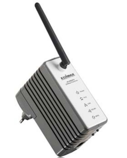
3. LED Definitions
LED |
Color |
Status |
Description |
Indicator |
|
|
|
PWR |
Red |
On |
Power is on. |
|
Green |
On |
The device runs normally. |
|
- |
Off |
Power is off or the device is down. |
WLAN |
Green |
On |
Radio switch is turned on. |
|
Green |
Blink |
Data is being transmitted. |
|
- |
Off |
Radio switch is shut off. |
WPS |
Green |
On |
Connection succeeds under Wi-Fi |
|
|
|
Protected Setup. |
|
Green |
Blink |
Negotiation is in progress under Wi-Fi |
|
|
|
Protected Setup. |
3
|
- |
Off |
Wi-Fi Protected Setup is disabled. |
|
PLC |
Green |
On/Blink |
When PLC rate 100Mbps, see note 1 |
|
Orange |
On/Blink |
When PLC rate in 80-100Mbps, see note 1 |
||
|
||||
|
Red |
On/Blink |
When PLC rate 100Mbps, see note 1 |
|
LAN |
Green |
On |
Connection succeeds. |
|
|
Green |
Blink |
Data is being transmitted. |
|
|
- |
Off |
No LAN connection. |
 Note: The PLC LED indicator turns “ON” when powerline link is detected. If the device is serving as a STATION, the LED indicator will blink to indicate transmit or receive powerline activity. If the device is serving as a CCO, the LED indicator will light steadily ON, even in the presence of powerline activity
4. Hardware Installation Procedure
1.Unpack the package and verify that all the items listed in the previous section are provided.
2.Connect the HomePlug product to the device which you want to add to a powerline network through the Ethernet cable.
3.Plug the HomePlug product to the power outlet.
4.This device with the HomePlug will join in the powerline network automatically.
5.Buttons :
Reset: |
The Reset button can restore the factory defaults. |
Group: |
The button is used to synchronous the private network name. |
WPS: |
This button is used for enabling WPS PBC mode. If WPS is |
|
enabled, press this button, and then the extender starts to accept |
|
the negotiation of PBC mode |
 Note: Do not press the Reset button unless you want to clear the current settings. The Reset button is in a small circular hole on the rear panel. If you want to restore the default settings, please press the Reset button gently for 3 seconds with a fine needle inserted into the hole and then release the button. The system reboots and returns to the factory defaults.
4
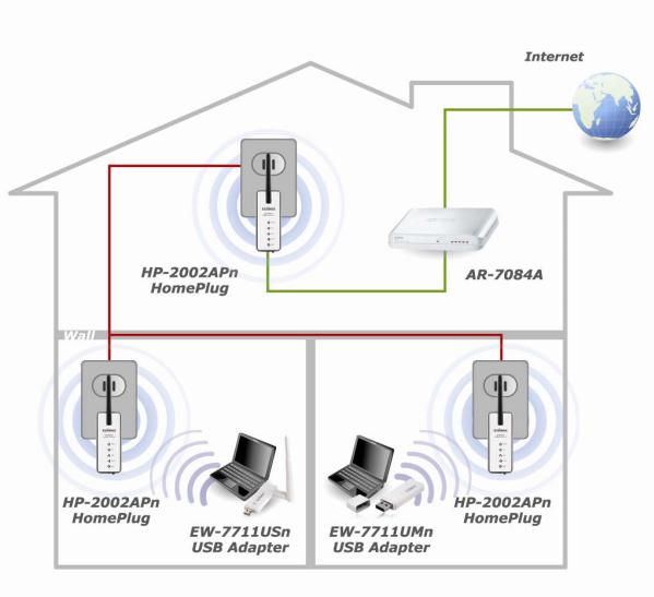
The following is the architecture of various applications of the HomePlug products.
Picture 1 :
5
5. Software Installation Procedure
The Configuration Utility for Windows 98SE/Me/2000/XP/Vista enables the users to identify HomePlug devices within the powerline network, measures data rate performance, ensures privacy and performs diagnostics by setting user defined secure powerline networks.
The Utility could help you to manager all of the HomePlug devices in the LAN. The Utility is not necessary when you use the internet via HP-2002APn.
Please follow the procedures below to install the utility. Please note that the following procedures are running in Windows XP, for other Windows operating systems, the procedures are similar.
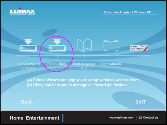
1. Click “ Setup Utility “ to install Utility .
6

2. The following screen will be displayed. Click “Next”.
3.Click “Next” to install the utility in the default folder or assign the destination folder where you would like to install the HomePlug utility.
7
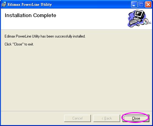
4. Click “Finish” to complete the installation.
8
6. Edimax PowerLine Utility
Click “Start” and select “All Programs\Edimax PowerLine Utility” in your computer, you will find the HomePlug utility. Please refer to the following
sections for the descriptions of how to use the utility.
Note :
The Utility can help you to find all (14Mbps / 85Mbps / 200Mbps) Powerline devies. But the 14Mbps and 85Mbps Powerline devices (complies with
HomePlug 1.0 and 1.1 standards ) can not connect with 200Mbps Powerline devices (complies with HomePlug AV standard).
6.1 Main
The Main screen provides lists of all HomePlug devices logically connected to
the computer when the utility is running. After connecting a HomePlug device to your computer, the utility will auto scan other HomePlug devices in the same network.
9
Upper Panel
The upper panel shows all local HomePlug devices connected to the computer’s NIC (Network Interface Card). In most cases, only one device will be seen. In situations where there are more than one local device being
connected, such as a USB or an Ethernet adapter, the user can select the local device by clicking on it and then click the “Connect” to connect to the selected
device. Once connected to the local device, the utility will automatically scan the power line periodically for any other HomePlug devices.
Lower Panel
The lower panel displays all the HomePlug remote devices, discovered on the current logical network. In the top of the table, you can see the total number of remote devices connected on the same network, the Network type (Public or Private) of the network and the scanning status.
Device Name: shows the default device name, which may be user re-defined. A user can change the name by either clicking on the “Rename” button or by clicking on the name and editing in-place.
An icon is usually shown with the name. A color distinction in icons is made between HomePlug 1.0, HomePlug 1.0 Turbo and HomePlug 1.1 devices. By default, the icon is always accompanied by a device name.
Password: by default the password column is blank and ‘Enter Password’ button can be used to enter it.
To set the Password of the device (it is required when creating a private network), first select the device by clicking on its name in the lower panel and then click on the “Enter Password”. A dialog box will appear. The selected device name is shown above the password field and the password can be verified by hitting the OK button. The Password field accepts the Device password in any case formats, with or without dashed between them.
Note 1: The device must be present on the power line (plugged in) in order for the password to be confirmed and added to the network. If the device could not be located, a warning message will be shown.
Note 2: Please find the password of the HomePlug device in the rear panel.
10
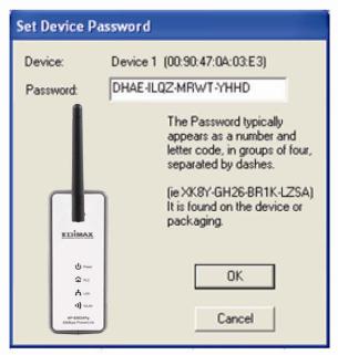
The “DAK” code is the password.
Quality: the status of the connection quality will be shown here.
Rate (Mbps): show the current data rate of the HomePlug device.
MAC Address: the device’s MAC address will be shown here.
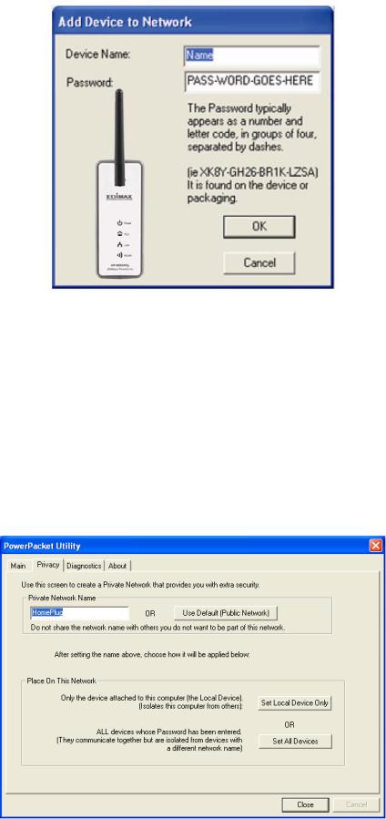
Add Button: it is used to add a remote device to the existing network by entering the device password of the device. A dialog box will appear as below. The dialog box allows the user to enter both a device name and the password. A confirmation box will appear if the password was entered correctly and if the device was found in the powerline network. If a device was not found, the user will be notified and suggestions to resolve common problems will be presented.
11
Scan Button: the button is used to perform an immediate search of the
HomePlug devices connected to the Powerline network. By default, the utility automatically scans every few seconds and updates the display screen.
6.2 Privacy
The Privacy screen provides the user with an option to maintain security for their logical network and also to select the devices that has to be included in the network.
12
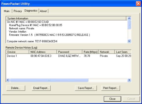
Private Network Name: All HomePlug devices are shipped using a default logical network (network name), which is normally “HomePlug”. If you wan to
set a privacy network, change the network name.
Use Default (Public Network): The user can always reset to the HomePlug
network (Public) by entering “HomePlug” as the network name or by clicking on the “Use Default (Public Network)”.
Set Local Device Only: The button can be used to change the private network
name to all of the local devices. If a new network name is entered, all the devices seen on the top panel of Main screen prior to this will be no longer present in the new network. You have to set the new network name to all local devices.
Set All Devices: The button is used to set the new network name (network password) to all HomePlug devices whose password has been entered for the same logical network. A dialog window will appear to report the success of this operation. For devices whose password is not entered, this operation will fail and will report a failure message.
13
6.3 Diagnostics
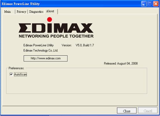
The Diagnostics screen shows System information and a history of all remote devices seen over a period of time.
Upper Panel
The Upper panel shows technical data concerning software and hardware present on the host computer which were used to communicate over HomePlug on the Powerline network. It includes powerline network name, computer user name, MAC Address of all NICs (Network interface card) connected to the computer, versions of all drivers and utilities, etc.
Lower Panel
The Lower panel contains a history of all remote devices seen on the computer over a certain period of time. All devices that were on the powerline network are listed here along with a few other parameters. Devices that are active on the current logical network will show a transfer rate in the Rate column; devices on other networks, or devices that may no longer exist are shown with a “?” in the Rate column. The following remote device information is available from the diagnostics screen:
Device Alias Name
Device MAC Address
14
Device Password
Device Last known rate
Device Last Known Network name
HomePlug chipset manufacturer name
Date device last seen on the network
MAC Firmware Version. (Turbo Only)
The diagnostics information displayed may be saved to a text file for later use, or can be printed for reference for a technical support call. Devices, which are not part of the network anymore, can be deleted using the delete button. A dialog window pops up with a confirmation message if we try to delete a device whose password has been entered.
6.4 About
The About screen shows the software version information. You can select “AutoScan” to turn on or off the auto-scan function.
15
7. Wireless Access Point Configuration
7.1 IP Setting
You can configure the HP-2002APn wireless setting by running the Setup Wizard in the CD-ROM provided in the package. The wizard provides quick setup for the SSID, wireless security of WPA-PSK and changing password of
HP-2002APn. When you start the Setup Wizard, you will get the following Welcome screen. Please choose the language to start with and follow the easy steps in the Wizard. No instruction for the Setup Wizard is given here.
If you lost the CD-ROM or you prefer the traditional web setup, please follow the procedures in this Manual to configure the HP-2002APn
The default IP address of HP-2002APn is ‘192.168.2.8’.Before you start the
Wizard or start to login HP-2002APn, you should make sure your computer’s IP address is in the same segment (192.168.2.XXX where XXX=10~253 ) of
HP-2002APn .
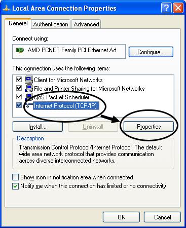
1. Click ‘Start’ button (it should be located at lower-left corner of your computer), then click control panel. Double-click Network and Internet Connections icon, click Network Connections, then double-click Local Area Connection, Local Area Connection Status window will appear as follows.
16
 Loading...