

Page 1

IC-3115W
User Manual
06-2012 / v1.0
Page 2

Notice According to GNU General Public License Version 2
Certain Edimax products include software code developed by third parties, software code is subject to the
GNU General Public License ("GPL") or GNU Lesser General Public License ("LGPL"). Please see the GNU
(www.gnu.org) and LPGL(www.gnu.org) Websites to view the terms of each license.
The GPL Code and LGPL Code used in Edimax products are distributed without any warranty and are
subject to the copyrights of their authors. For details, see the GPL Code and LGPL Code licenses. You can
download the firmware-files at http://www.edimax.com under "Download" page.
Copyright
Copyright Edimax Technology Co., Ltd. all rights reserved. No part of this publication
may be reproduced, transmitted, transcribed, stored in a retrieval system, or translated
into any language or computer language, in any form or by any means, electronic,
mechanical, magnetic, optical, chemical, manual or otherwise, without the prior written
permission from Edimax Technology Co., Ltd.
Edimax Technology Co., Ltd. makes no representations or warranties, either expressed
or implied, with respect to the contents hereof and specifically disclaims any warranties,
merchantability, or fitness for any particular purpose. Any software described in this
manual is sold or licensed as is. Should the programs prove defective following their
purchase, the buyer (and not this company, its distributor, or its dealer) assumes the entire
cost of all necessary servicing, repair, and any incidental or consequential damages
resulting from any defect in the software. Edimax Technology Co., Ltd. reserves the right to
revise this publication and to make changes from time to time in the contents hereof
without the obligation to notify any person of such revision or changes.
The product you have purchased and the setup screen may appear slightly different
from those shown in this QIG. For more information about this product, please refer to the
user manual on the CD-ROM. The software and specifications are subject to change without
notice. Please visit our website www.edimax.com for updates. All brand and product names
mentioned in this manual are trademarks and/or registered trademarks of their respective
holders.
Edimax Technology Co., Ltd.
Add: No. 3, Wu-Chuan 3rd Rd., Wu-Ku Industrial Park, New Taipei City, Taiwan
Tel: +886-2-77396888
Email: sales@edimax.com.tw
1
Page 3

Contents
Copyright ........................................................................................................................................................................... 1
Contents ............................................................................................................................................................................ 2
Chapter I: Introduction ..................................................................................................................................................... 4
1.1 Features of your New Network Camera ................................................................................................................. 4
1.2 Safety Instructions .................................................................................................................................................. 4
1.3 Package Contents .................................................................................................................................................... 5
1.4 Familiarizing Yourself with Your New Network Camera ......................................................................................... 6
1.5 Installing the Network Camera ............................................................................................................................... 8
1.6 Installing the Network Camera with WPS ............................................................................................................... 9
Chapter II: Accessing the Camera’s Web Interface ........................................................................................................... 9
2.1 Installing EdiView Finder ....................................................................................................................................... 10
2.2 Connecting to the Camera’s Web User Interface and Installing the ActiveX Plugin (IE only) .............................. 11
2.3 Live Video Monitoring ........................................................................................................................................... 16
Chapter III: Setting Up the Network Camera .................................................................................................................. 19
3.1 Basic Network Settings.......................................................................................................................................... 20
3.2 Wireless ................................................................................................................................................................. 23
3.3 Dynamic DNS ......................................................................................................................................................... 28
3.4 Date & Time .......................................................................................................................................................... 30
3.5 Users ..................................................................................................................................................................... 32
3.6 UPnP ...................................................................................................................................................................... 35
3.7 Bonjour .................................................................................................................................................................. 36
Chapter IV: Video Configuration ..................................................................................................................................... 37
4.1 Video Settings ....................................................................................................................................................... 37
4.2 Image ..................................................................................................................................................................... 38
Chapter V: Event Configuration ...................................................................................................................................... 40
5.1 Motion Detection Setup ........................................................................................................................................ 40
5.1.1 Detection Region ............................................................................................................................................ 41
5.1.2 FTP .................................................................................................................................................................. 44
5.1.3 SMTP .............................................................................................................................................................. 46
2
Page 4

Chapter VI: System Configuration ................................................................................................................................... 49
6.1 Basic Settings ........................................................................................................................................................ 49
6.2 Advanced Settings ................................................................................................................................................. 50
Chapter VII: System Status .............................................................................................................................................. 52
7.1 System Information ............................................................................................................................................... 52
7.2 System Log ............................................................................................................................................................ 54
Chapter VIII: Advanced Operations ................................................................................................................................ 56
8.1 Applying for a DynDNS Account ............................................................................................................................ 56
8.2 Applying for a Free no-ip.com Account ................................................................................................................ 61
Chapter IX: Windows Surveillance Utility ....................................................................................................................... 64
9.1 Installing the Network Camera Administration Software ..................................................................................... 64
9.2 Using the Network Camera Surveillance Software ............................................................................................... 68
9.3 Configuring the Network Camera Surveillance Software ..................................................................................... 71
9.3.1 Camera Configuration .................................................................................................................................... 71
9.3.2 General Settings ............................................................................................................................................. 80
9.4 Changing the Display Layout ................................................................................................................................. 87
9.5 Full-Screen Mode .................................................................................................................................................. 90
9.6 Scan ....................................................................................................................................................................... 91
9.7 Zoom-In/Zoom-Out ............................................................................................................................................... 92
9.8 PTZ ......................................................................................................................................................................... 93
9.9 Snapshot................................................................................................................................................................ 94
9.10 Recording ............................................................................................................................................................ 95
9.11 Video Playback .................................................................................................................................................... 96
Chapter X: Accessing the Network Camera remotely ..................................................................................................... 97
10.1 Configuring the iOS Surveillance Software ......................................................................................................... 97
10.2 Configuring the Android Surveillance Software .............................................................................................. 113
10.3 Configuring myedimax.com .............................................................................................................................. 135
10.4 Troubleshooting ................................................................................................................................................ 139
Appendix A .................................................................................................................................................................... 140
3
Page 5

Chapter I: Introduction
1.1 Features of your New Network Camera
Congratulations on purchasing this miniaturized network camera! Its tiny size
maximizes portability and facilitates installation; you can easily install the
camera almost anywhere you need video surveillance. If no Ethernet cable is
available at the location you wish to install this Network camera, you can use
the built-in wireless network capabilities to connect to your network, and save
the cost of cabling.
Other highlights of this network camera include:
Compact size and lightweight design, and can be installed anywhere.
Mounting hole located behind camera, compatible with most camera tripods.
Wireless network connectivity with data security (encryption), ensuring
secure wireless data transfer.
Fixed-focus lens, works in most environments.
1.2 Safety Instructions
Please obey the safety instructions listed below when you’re using this network
camera, or you could cause harm to this camera and / or yourself! Also,
warranty will be voided if you violate these safety instructions
This network camera is sophisticated electronic device; do not drop it from
high places.
Do not place this network camera in hot / humid places, or in direct sunlight.
This network camera is not a toy; keep it out of the reach of children.
Do not insert any parts or accessories of this network camera into your body.
If you want to use this camera in a location where it may be exposed to dirt
or water, a secure and water-proof camera housing is required.
Do not forcefully pull any cords connected to this camera.
4
Page 6

The camera will become hot after long periods of use. Refrain from touch the
camera with your bare hands, and do not cover this camera with paper or
cloth.
If the network camera falls into water while powered, do not attempt to
retrieve it yourself! Find a qualified electric technician for help.
1.3 Package Contents
Please check the contents of your new network camera when you unpack the
package. If any items are missing, please contact your dealer of purchase for
help.
Network camera (1 pcs)
Power adapter (1 pcs)
Ethernet cable (1 pcs)
Mounting kit (1 pcs)
CD with utility software and user manual (1 pcs)
Quick installation guide (1 pcs)
Cloud ID card (1 pcs)
5
Page 7
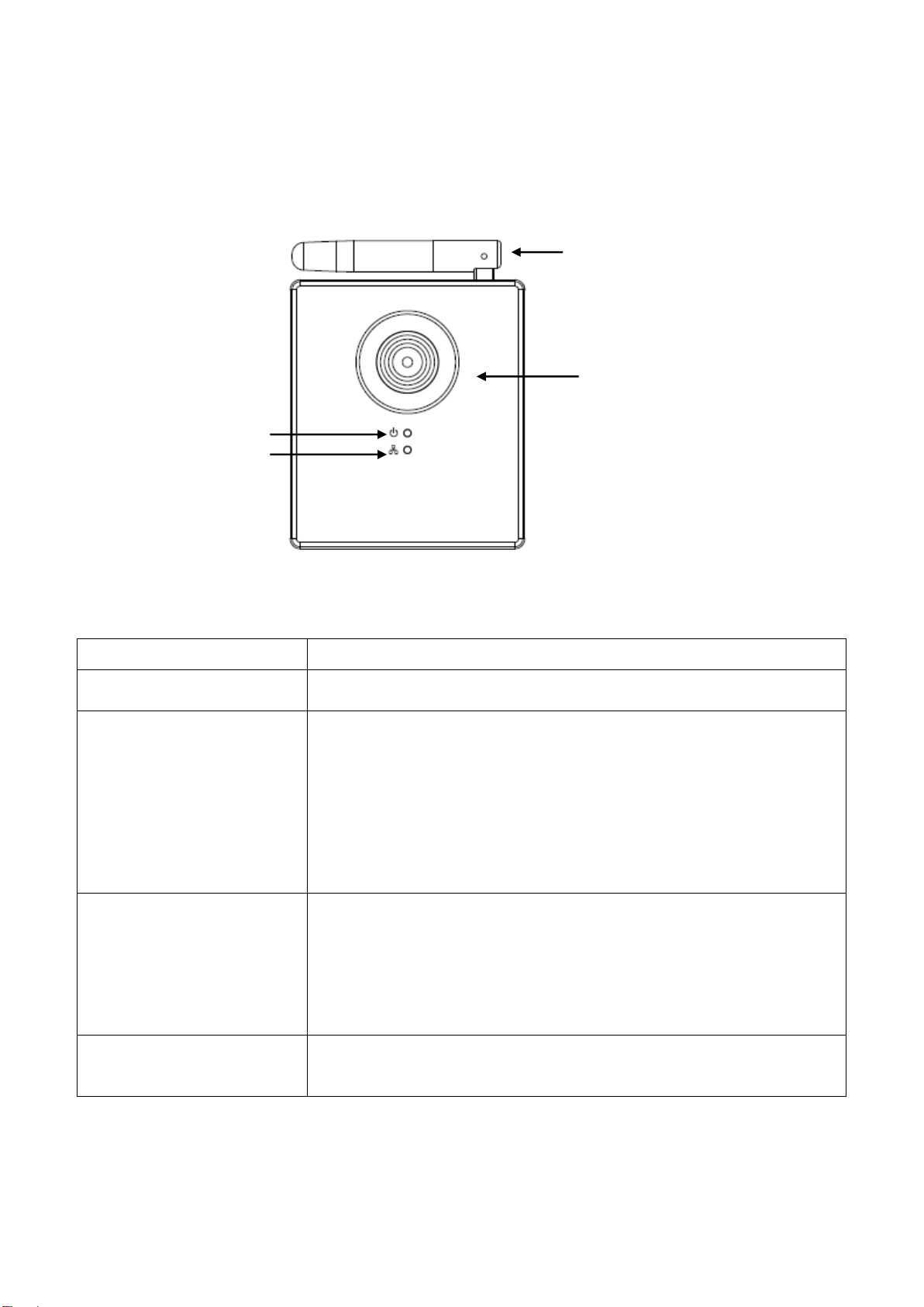
1.4 Familiarizing Yourself with your New Network Camera
Item
Description
1 - Lens
Network camera’s lens. Please keep the lens clean
and do not touch it directly with your finger.
2 – Power/Cloud LED
When the camera is first powered on, the camera
will initialize itself, and the Power/Cloud LED will
light up for approximately 30 seconds. After
initialization is complete, the LED will flash for 10 to
15 seconds while camera attempts to connect to
the cloud.
When the LED stops flashing and stays on, the
camera has successfully connected to the cloud.
3 – LAN/Wi-Fi/WPS
LED
This LED will light up when the network camera is
connected to Ethernet network, and it will flash
rapidly when transferring data (It will flash slowly
when using WPS).
(The LEDs can be switched off even when the
network camera is powered on)
4 - Antenna
Wireless antenna. Please keep the antenna
perpendicular to the ground for best signal
reception.
Power / Cloud LED
LAN/Wi-Fi/WPS LED
Lens
Antenna
[Front]
6
Page 8

[Back]
Item
Description
1 - Tripod connector
This mounting hole is compatible with most camera
tripod ors camera stands, so you can fix the camera
at a secure place.
2 - LAN
Connects to your local area network.
3 - Power
Connects to the 5V DC power adapter.
4 - WPS / Reset
Press this button for 2 seconds to begin WPS
connection.
If the network camera is not functioning properly,
you can press and hold this button for more than
10 seconds to clear all settings, including the
administrator password.
LAN port
Tripod Connector
WPS / Reset Power
7
Page 9
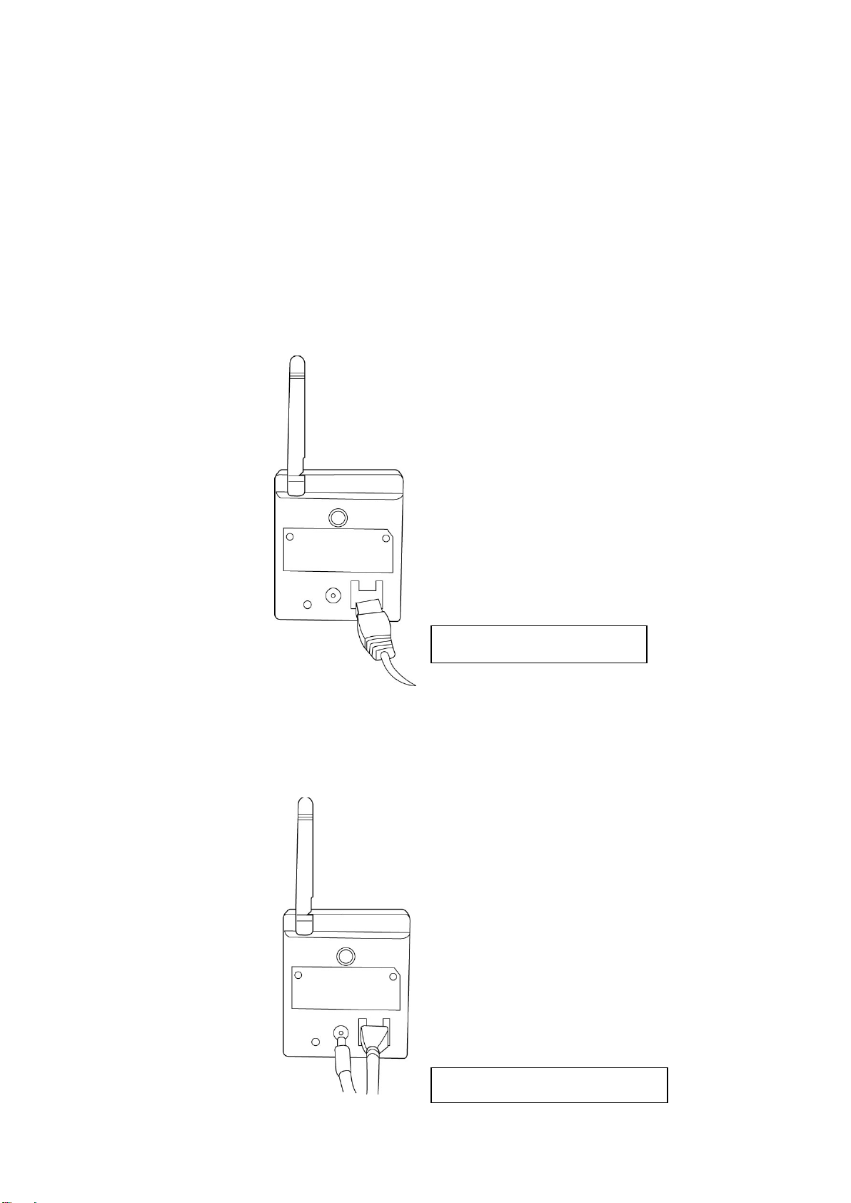
1.5 Installing the Network Camera
Connect Ethernet net cable
Connect DC power cable to DC Jack
Please follow the following instructions to set up your new network camera.
1. Secure the network camera to the tripod or camera stand using the mounting
hole.
2. Connect an Ethernet cable to the LAN port. For first-time installation you’ll
generally need an Ethernet cable to perform configuration. However, if this
network camera is configured to connect wirelessly, for example you will
connect using WPS, you can skip this step.
3. Plug the DC power adapter to a power outlet in the wall.
4. Connect the DC power cable to the network camera’s DC power connector.
8
Page 10
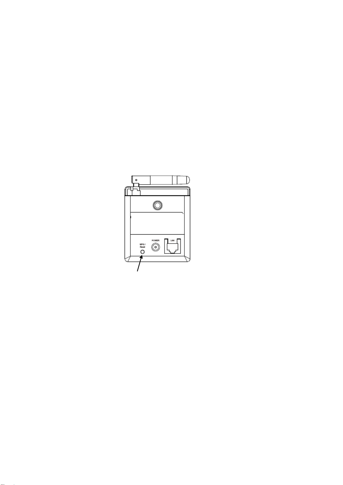
If everything works as intended, you should see the POWER LED light up (and
WPS / Reset
the Ethernet LED, if an Ethernet cable is inserted). If not, please recheck
every step and try again, or ask your dealer of purchase for help.
Please note if you configured the network camera to switch LED lights off, the
two LED lights won’t light up.
1.6 Installing the Network Camera with WPS
This network camera can establish a wireless connection with a wireless access
point by means of its hardware Wi-Fi Protected Setup (WPS) button.
To activate a WPS connection, press the WPS / Reset button on the network
camera for two seconds, the LAN/Wi-Fi/WPS LED will start flashing regularly.
Press the WPS button on the root wireless access point within 120 seconds. The
network camera and the wireless AP will automatically establish a secure WPS
connection.
When the connection is successfully established, the LAN/Wi-Fi/WPS LED will
light up and may flash irregularly, to indicate a connection has been made and
data is being transmitted.
9
Page 11
Chapter II: Accessing the Camera’s Web Interface
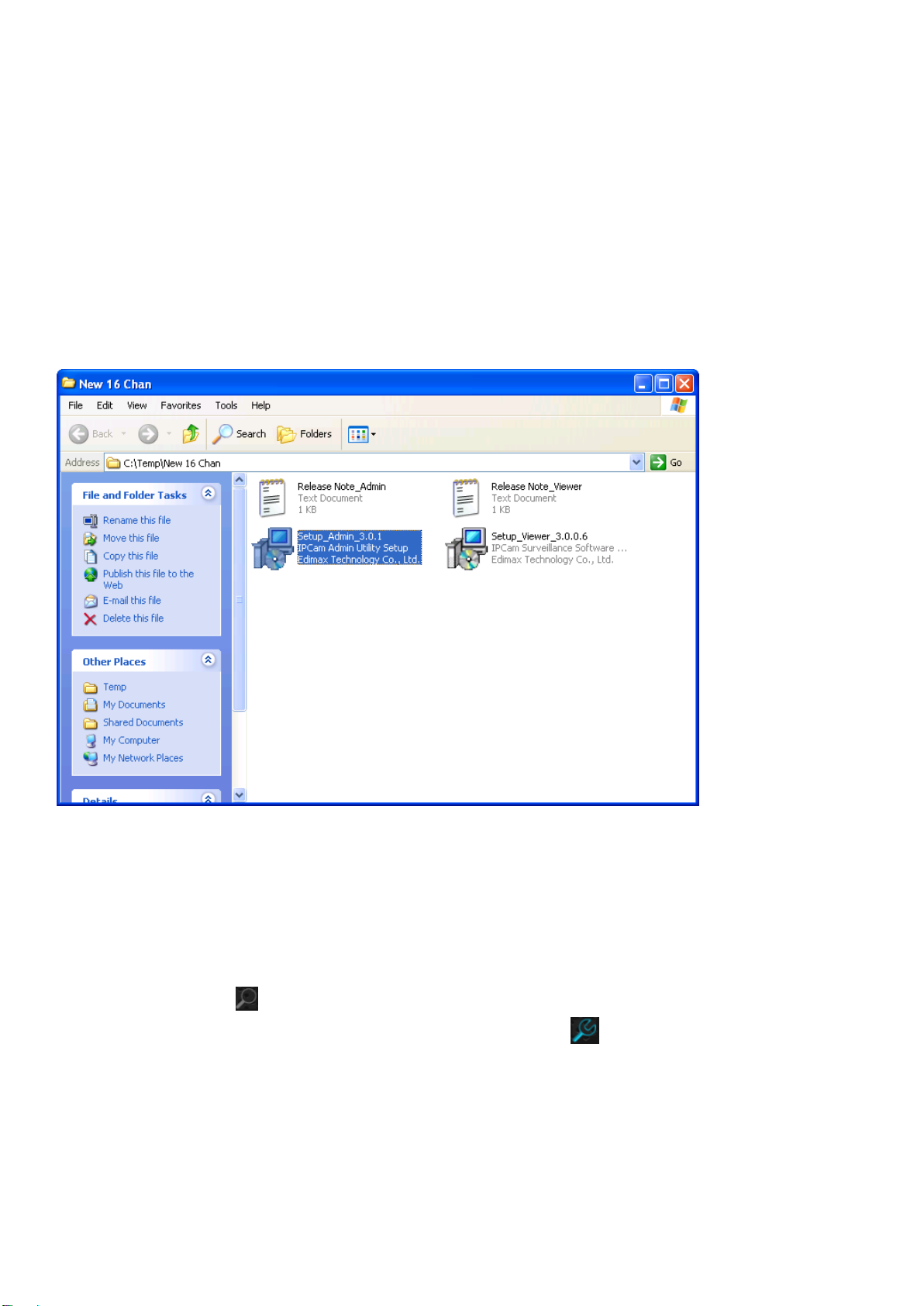
2.1 Installing EdiView Finder
Please first install the EdiView Finder utility, which allows you to locate all
network cameras on the local network.
Insert the user manual CD-ROM supplied with the network camera into your CD
drive. The CD should automatically begin the installation. If it does not, please
double-click the installation icon for the admin software in the ‘Utility’ folder.
After installation is complete, run EdiView Finder.
EdiView Finder will list all Ediamax network cameras found on the local network,
with their IP addresses and MAC addresses.
You can click the icon to refresh the list of network cameras on the local
network, or select a network camera and click the Icon to configure it. To
preview the image of the network camera, please click the rectangular block to
the right of the camera listing, and enter the camera’s password (default: 1234).
10
Page 12
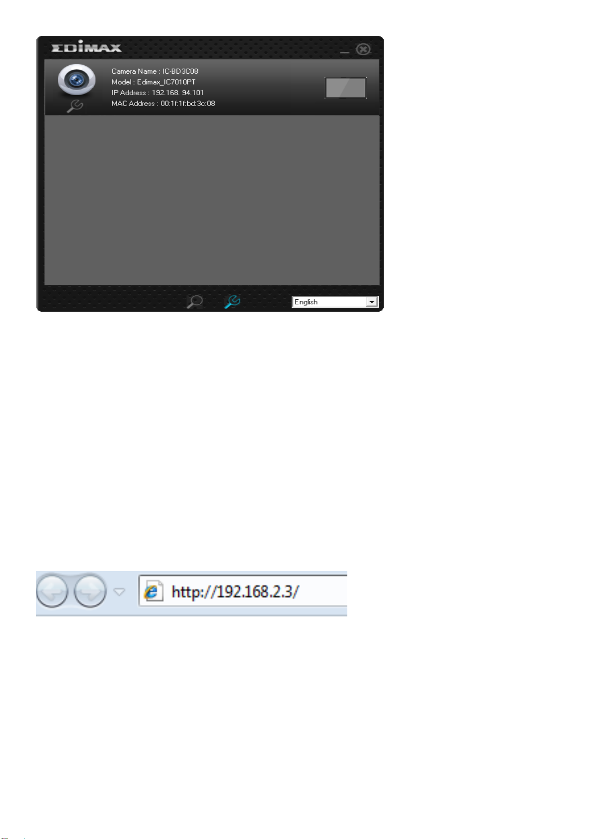
Note: Preview is only available when the rectangular block is colored blue.
2.2 Connecting to the Camera’s Web User Interface and Installing the ActiveX Plugin (IE
only)
For first-time installation, you can connect to the network camera by entering
its IP address into the address bar of Internet Explorer. The camera’s IP address
can be found by running EdiView Finder. Should EdiView Finder fail to find the
camera, you may also attempt to connect using the camera’s default IP address,
192.168.2.3. However, to do so you must first change your computer’s IP
address to one beginning with 192.168.2.x. Please see Appendix A for more
details.
The use login screen will appear when you get connected:
11
Page 13

The network camera’s administrator username is ‘admin’ (lower case) and the
password is ‘1234’ by default. Click ‘OK’ or press the ‘ENTER’ key on your
keyboard when you finish entering the username and password.
When you connect to the network camera for the first time, you may see the
following message:
This message prompts you to install the ActiveX plugin before you can see the
video from Network camera. Click the ‘Download ActiveX’ link to install the
ActiveX plugin:
12
Page 14
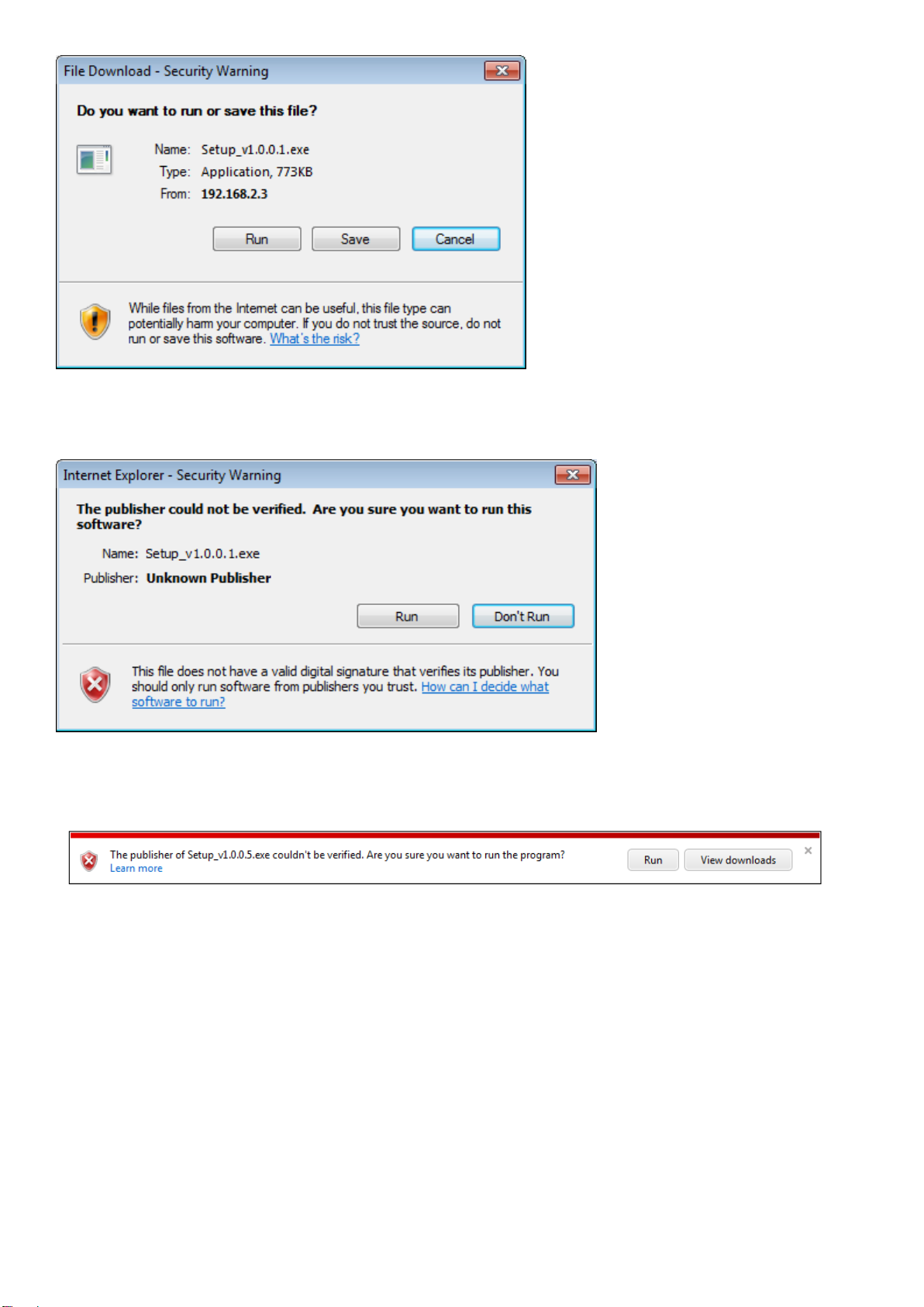
Click ‘Run’ to start installation. After a few seconds, you’ll see this message:
For IE9: The message will appear at the bottom of Internet Explorer:
Click ‘Run’ to begin installation. You may see a UAC (User Account Control)
message after you click the ‘Run’ button:
13
Page 15
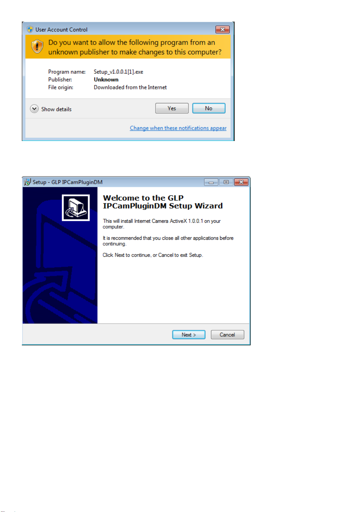
Click ‘Yes’ to continue. Installation will begin:
Click ‘Next’ and ‘Install’ when you’re prompted to install ActiveX control. When
you see this message, installation is complete:
14
Page 16
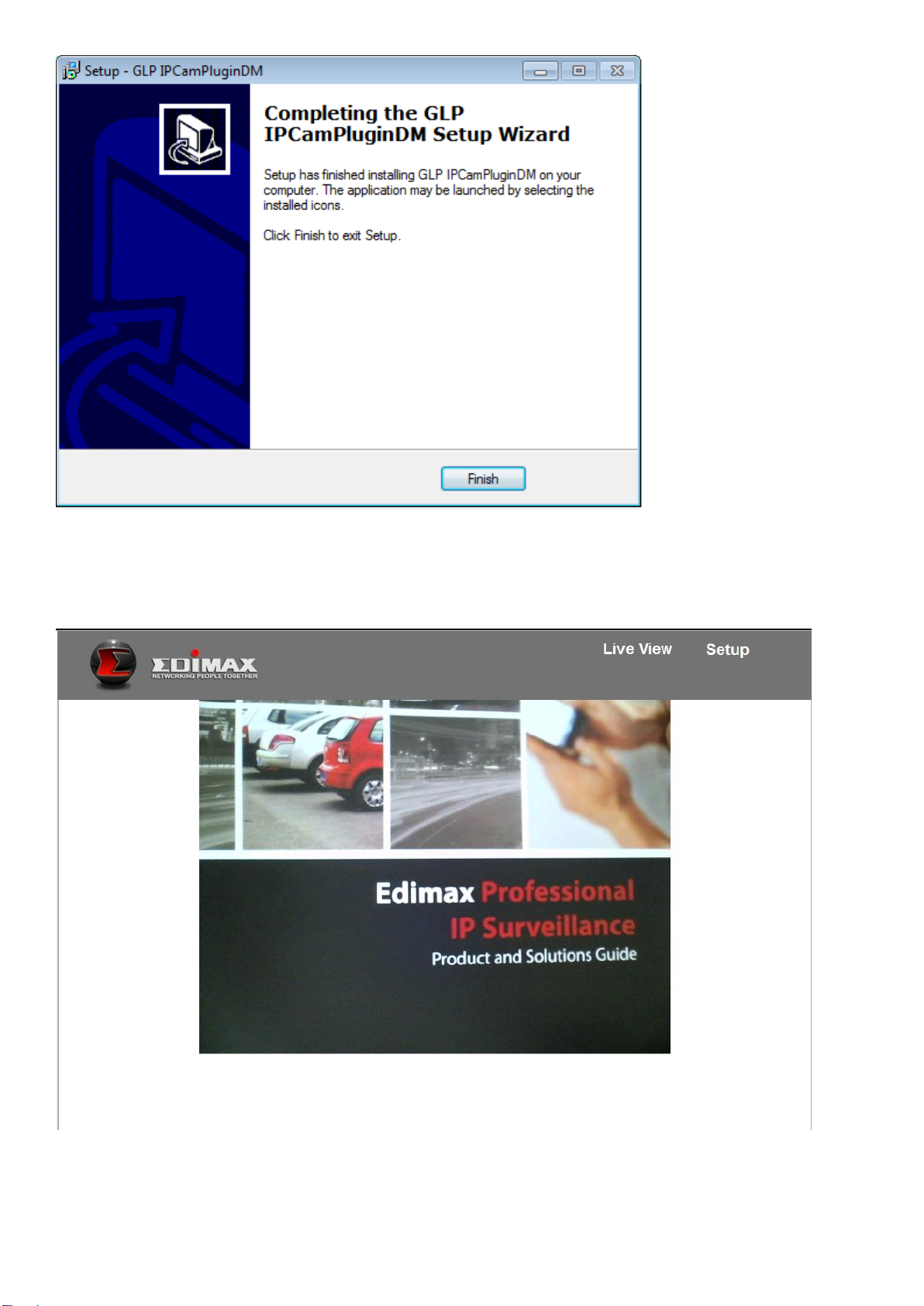
Click ‘Finish’ to close the window. Now, go back to web browser window and
login again, you should be able to see camera’s image:
15
Page 17
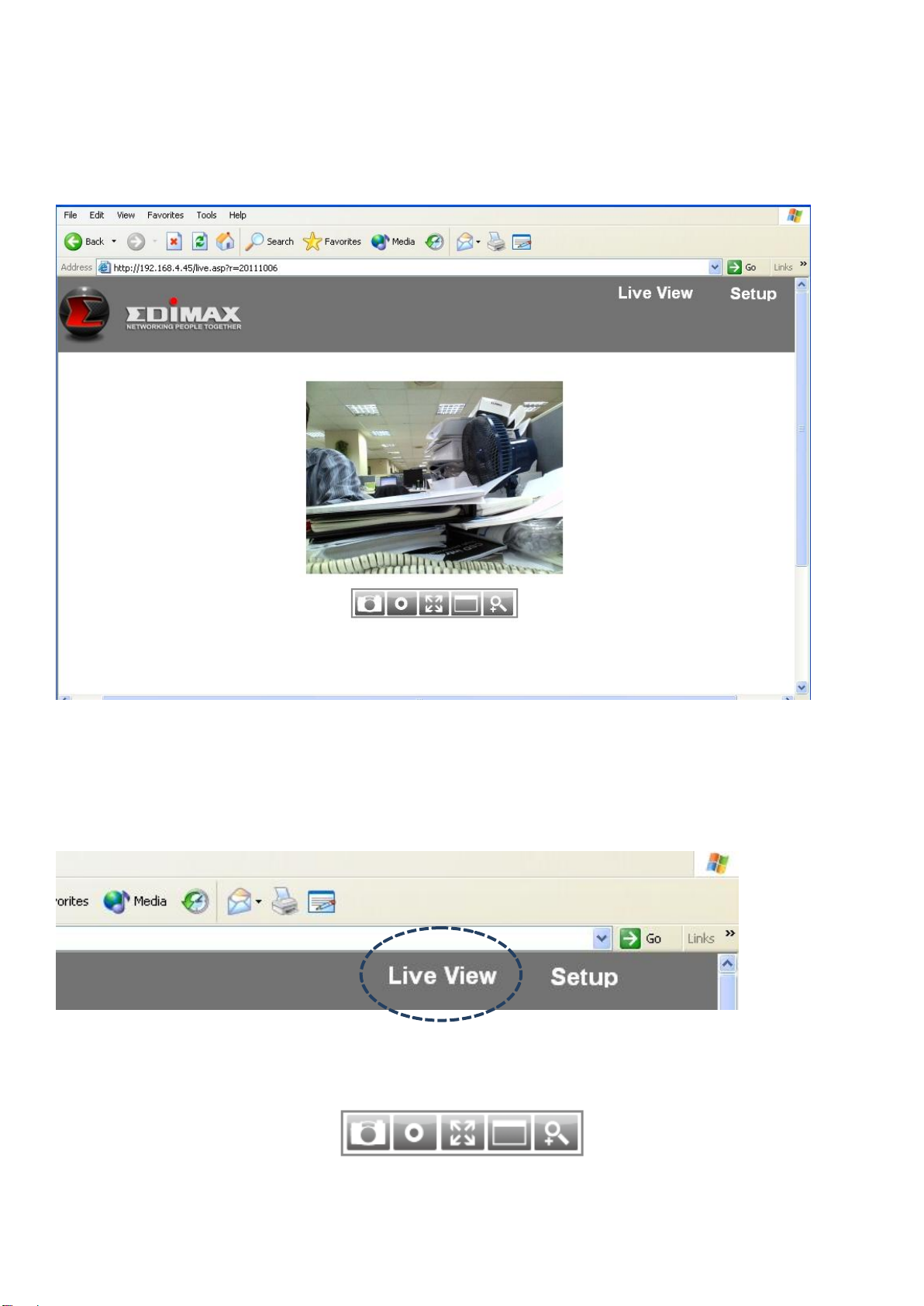
2.3 Live Video Monitoring
To view the live video from the network camera, please log onto the network
camera’s web interface as described in the last chapter, and you can see the live
video view:
When you’re in the other setup pages of the network camera, you can click the
‘Live View’ link located at the upper-right corner of the network camera’s web
interface at any time to return to this page:
There are also some functions you can use in the camera’s live view page:
16
Page 18
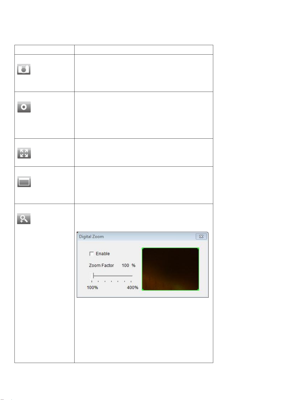
Item
Description
Snapshot
Take a snapshot (save a picture) of the
current live view. You’ll be prompted to
select a folder in your computer to save
the snapshot in.
Record
Start recording video. You’ll be prompted
to select a folder in your computer. Click
the icon once to begin recording, the icon
will turn blue. Click it again to stop
recording.
Fit to window
Click this button and the live view area will
adjust according to the size of your web
browser.
Full Screen
Click this button and the live view will
expand and fit the size of your computer
monitor. Press the ‘Esc’ key on your
keyboard to exit full screen.
Digital Zoom
Click this button and a new window will
pop up:
Check the ‘Enable’ box to enable digital
zoom (enlarge video so you can see
objects in detail). Drag the slide bar from
100% (no enlargement) to 400% to enlarge
the image. The level of enlargement will be
displayed in the ‘Zoom Factor’ field.
The descriptions of these items are listed below:
17
Page 19
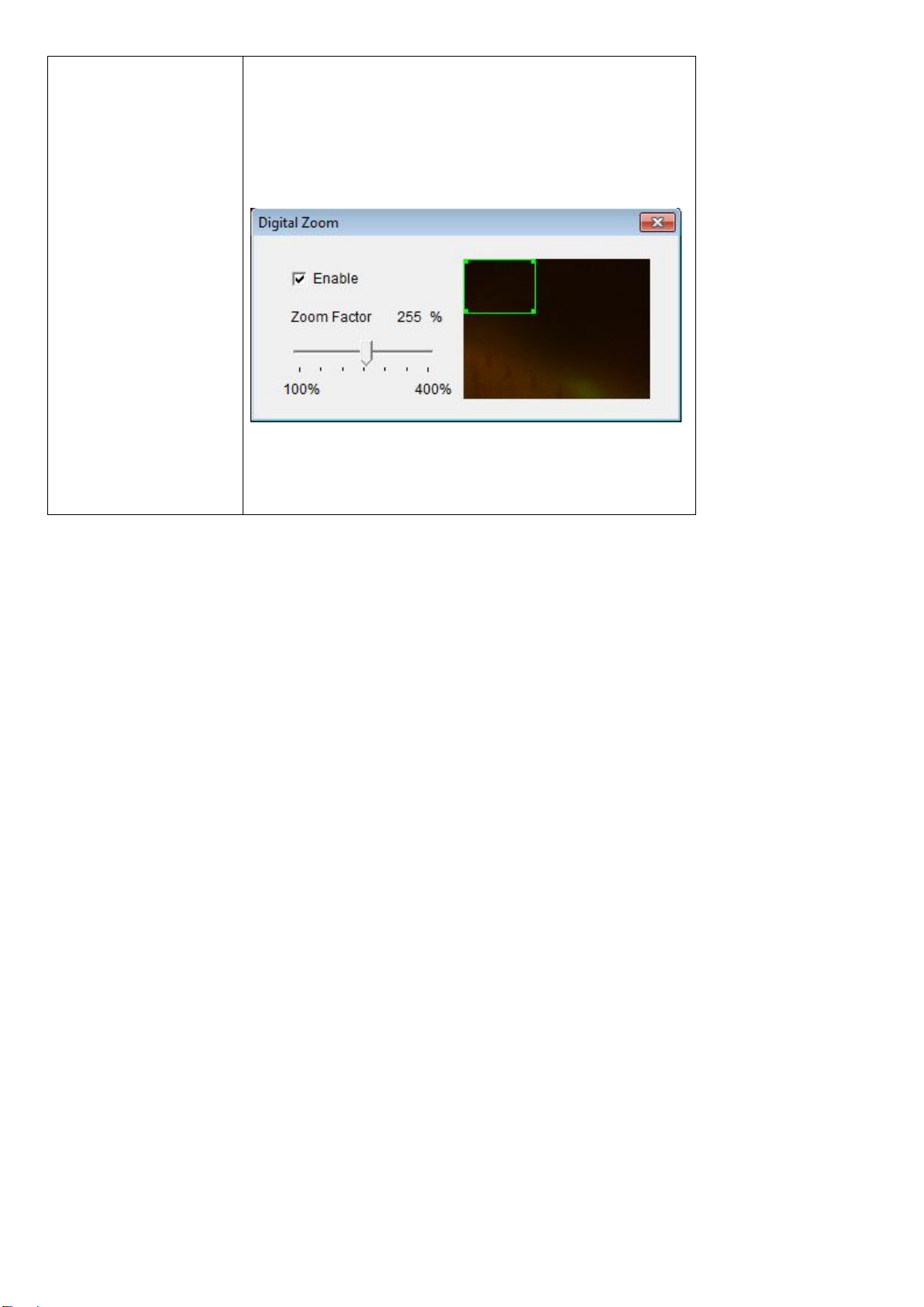
When you’re enlarging an image (i.e. Zoom
Factor > 100%), a green rectangle will
appear in the image area:
Drag the green rectangle to move the
position of the enlarged area in the image.
18
Page 20
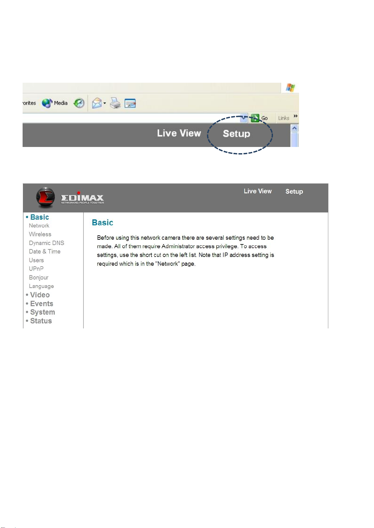
Chapter III: Setting Up the Network Camera
To set up the network camera, please log onto the network camera’s web
interface and click the ‘Setup’ link in the upper-right corner:
The setup menu will appear:
There are five setup categories: Basic, Video, Events, System, and Status, which
are located at the left of the web interface. When you click on the link of a
category, it will expand and show a sub-menu.
Please refer to following chapters for detailed instructions.
19
Page 21
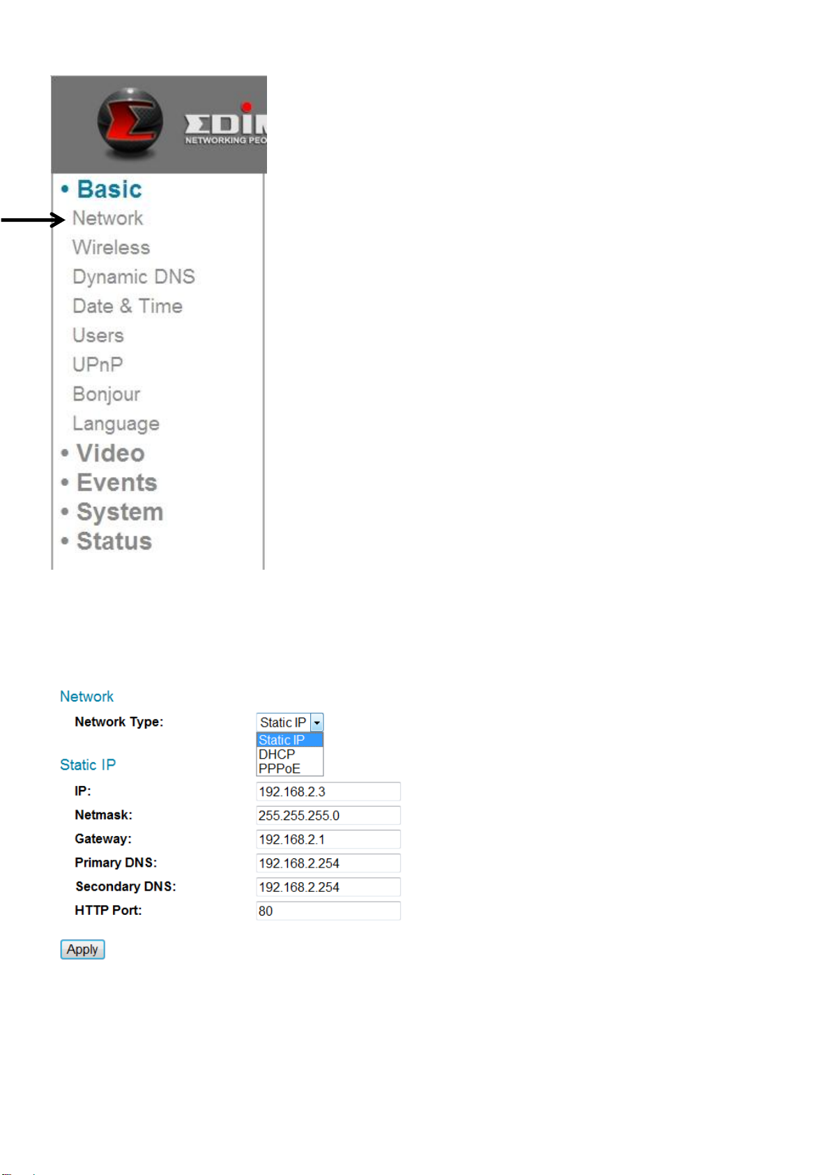
3.1 Basic Network Settings
In this menu, you can setup Ethernet network settings.
(NOT wireless network!)
The descriptions of these items are listed below:
20
Page 22
Item
Description
Network Type
Select the type of Ethernet connection: Static IP,
DHCP, and PPPoE. Please select one from
dropdown menu. If you’re not sure, please
consult your network administrator or ISP.
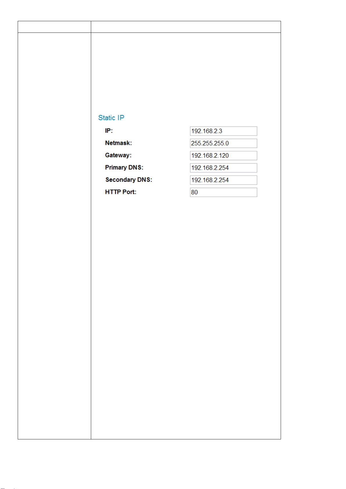
Static IP:
IP: Please assign an IP address to this
network camera.
Netmask: Please input the netmask of the IP
address.
Gateway: Please input the gateway address
of your network.
Primary DNS: Input the IP address of your
DNS server.
Secondary DNS: Input the IP address of a
secondary (backup) DNS. You can leave this
field blank if no secondary DNS is available.
HTTP port: The default web port number is
80. If you want to change it, please enter a
port from 1024 to 65535 in this field. When
you connect to this network camera next
21
Page 23
time, you will have to add a colon and port
number after the network camera’s IP
address. For example, if the camera’s IP
address is 192.168.2.3 and the HTTP port
number is 82, you will have to enter
‘http://192.168.2.3:82’ in your web
browser’s address bar.
DHCP: The network camera will obtain its IP
address from a DHCP server on your local area
network automatically.
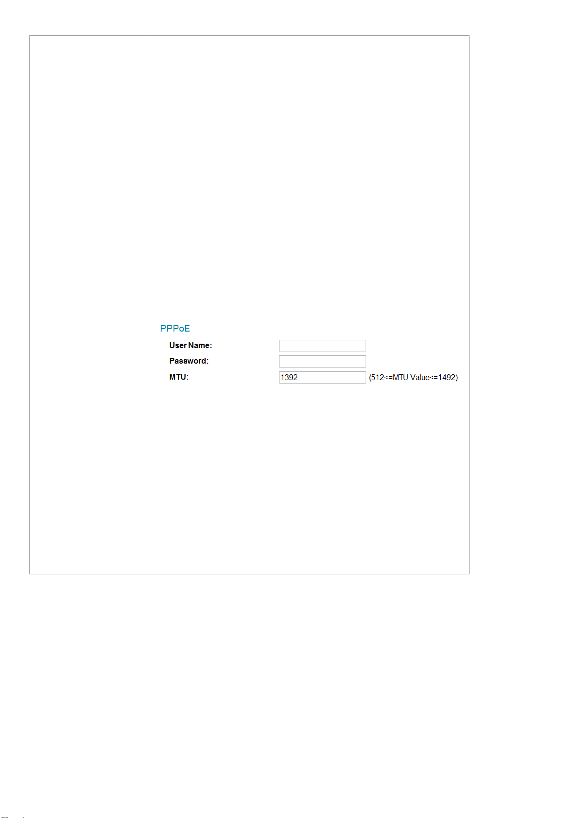
PPPoE: Network camera will connect to the
network via PPPoE.
Please input your PPPoE user name and
password, and input a MTU value when
required.
Please note: In some cases you can improve
network efficiency or correct connection
problems by setting a new MTU value, however,
in most cases you don’t have to change the MTU
setting.
Click the ‘Apply’ button to save changes you made.
22
Page 24
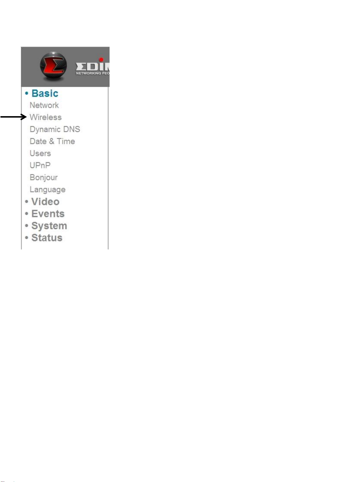
3.2 Wireless
You can establish wireless connections to other network devices such as a
network AP.
23
Page 25
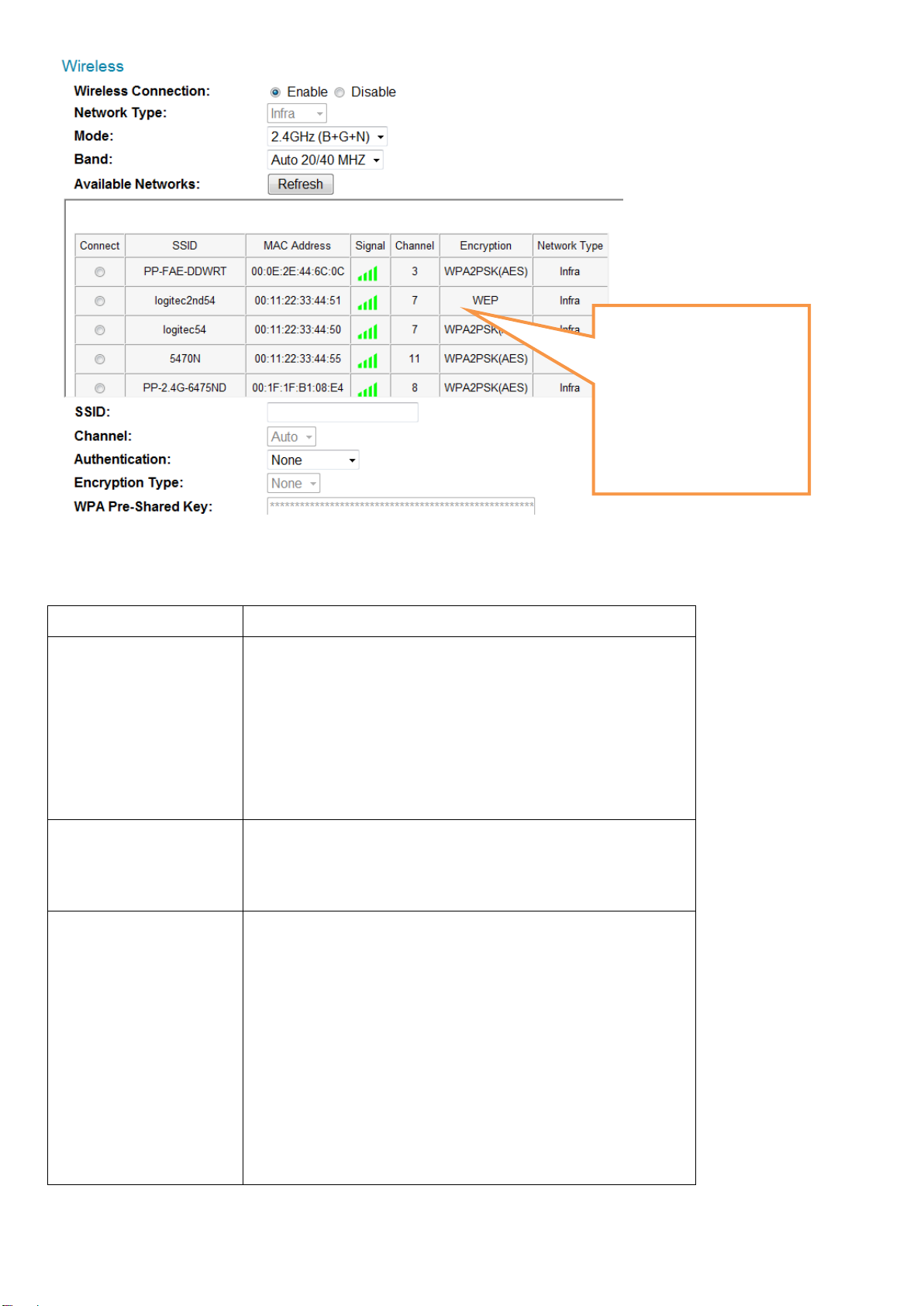
Item
Description
Wireless
Connection
You can enable or disable wireless
functionality here.
Please note: You can switch wireless
network off, but you can’t switch wired
Ethernet off.
Network Type
Select the type of network you wish to
connect: Infra (infrastructure: wireless
access point).
Mode
Select the wireless operating mode:
B (802.11b, maximum 11Mbps)
G (802.11g, maximum 54Mbps)
N (802.11n, maximum 150Mbps).
You can select mixed mode (2.4GHz
B+G+N) so the network camera will work
with all kinds of wireless network. If you
When you enter this
page, The network
camera will scan for
wireless devices nearby
automatically and
display them here.
The descriptions of these items are listed below:
24
Page 26

select B, G, or N only, then the network
camera will be able to communicate with
wireless networks of the same operating
mode only.
Band
Select wireless band: 20MHz only or
20/40MHz auto switch. It’s recommended
to select ‘Auto 20/40MHz’.
Available
Networks
The network camera will list all nearby
networks and their parameters in this
field. If the network you wish to connect to
does not appear here, click ‘Refresh’ to
rescan again. You can click ‘Refresh’ button
as many times as you wish, until the
network you wish to connect to appears in
the list.
If you wish to connect to a specific
network, select the radio button of the
network you wish to connect to (under the
‘Connect’ field), and the network’s
connection parameter will appear in the
fields below.
Tips: If you can’t see the network you wish
to connect to, even after refreshing many
times, please move the network camera
closer to the network’s access point).
SSID
Input the network’s SSID (access point’s
wireless name) here, or select a network
from the network list above.
If the network you wish to connect to is a
‘hidden’ network (SSID is hidden from the
public), you will have to input the SSID
manually.
Channel
Select a wireless channel number. Use
‘Auto’ to select a channel automatically.
25
Page 27

Authentication
Select authentication type:
None: No encryption
WEP: Use WEP encryption
WPA-PSK: Use WPA with PSK encryption.
WPA2-PSK: Use WPA2 with PSK
encryption.
The authentication type you select here
must be identical to the access point’s
setting.
Encryption Type
Select wireless encryption type. This
option will vary depending on the
authentication type of the network you
wish to connect.
The encryption type you select here must
be identical to the access point’s setting.
WPA Pre-shared
Key
Input the WPA pre-shared key here, it
must be identical to the access point’s
setting.
(This field is not available when the
authentication type is none or WEP).
WEP Key Format
Select the WEP key’s format: Hex or ASCII.
This setting must be identical to the setting
of the network you wish to connect to.
WEP Key length
Select the WEP key’s length: 64 or 128-bit.
This setting must be identical to the setting
of the network you wish to connect to.
WEP Key
Input the WEP key here.
26
Page 28

This setting must be identical to the setting
of the network you wish to connect to.
Item
Description
Self PinCode
Displays the 8-digit pin code of this
network camera. Write this number down
because you’ll need this number to
connect with other WPS-enabled network
devices when requested.
Configure via
Push Button
Click the ‘Start PBC’ button to start a
PBC-style WPS pairing sequence: Click this
button, then push the WPS button on the
access point (or click a software button in
the access point’s configuration web
page).
You must press the WPS button of the
wireless device you wish to connect to
within 120 seconds.
Configure via
PinCode
Click ‘Start PIN’ to start a PIN-style WPS
pairing sequence. You have to input the
WPS registrar’s SSID in the ‘Registrar SSID’
field first.
You can also set up an encrypted wireless connection through WPS (Wi-Fi
Protected Setup):
The descriptions of these items are listed below:
Click the ‘Apply’ button to save changes you made.
27
Page 29
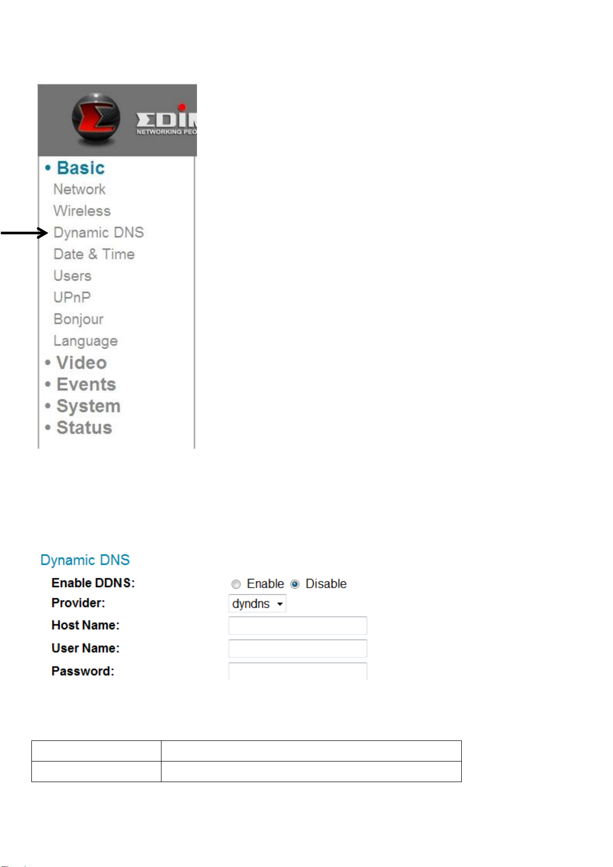
3.3 Dynamic DNS
Item
Description
Enable DDNS
Select ‘Enable’ to enable DDNS
If your Internet service provider didn’t issue a fixed IP address, you can use this
function to report your current IP address to a dynamic DNS service provider, so
you can locate your network camera without having a fixed IP address.
The descriptions of these items are listed below:
28
Page 30

functionality, or select ‘Disable’ to disable
DDNS functionality.
Provider
Select your dynamic DNS service provider
from the dropdown menu.
Host Name
Input the hostname you registered with
the DDNS service provider.
User Name
Input the user name you registered with
the DDNS service provider.
Password
Input the password you registered with
the DDNS service provider.
Click the ‘Apply’ button to save changes you made.
TIPS: You can register for free (or paid) dynamic DNS service from the following
website:
Dyndns: www.dyndns.org
Refer to Chapter VIII for DDNS application.
29
Page 31
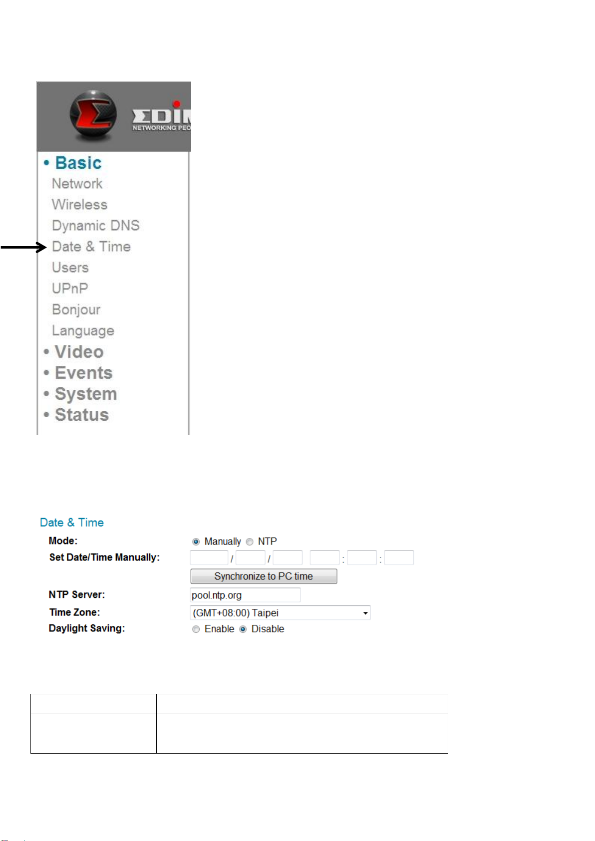
3.4 Date & Time
Item
Description
Mode
Select date & time setup mode:
You can set up the network camera’s system date and time here. Maintaining a
correct system time is very essential when you need to replay recorded video.
The descriptions of these items are listed below:
30
Page 32

Manually: Set time manually.
NTP: Use NTP (Network Time Protocol) to
set up date and time automatically via the
network. If you have an Internet
connection or there’s a NTP server on your
local network, you can select this function
to help you keep the network camera’s
date and time correct.
Set Date/Time
Manually
There are 6 fields for you to fill, to enter
the current date and time. The format is:
YYYY/MM/DD HH:MM:SS
Synchronize to
PC time
Click this button to fill the date / time
fields with your computer’s date and time.
NTP Server
Input NTP server’s hostname or IP address.
Time Zone
Select the time zone of the place you live
from the dropdown menu.
Daylight Saving
If the area you live in uses daylight saving,
select ‘Enable’, or select ‘Disable’ when
daylight saving is not used.
Click the ‘Apply’ button to save changes you made.
31
Page 33

3.5 Users
Besides the default system operator account ‘administrator’, you can add
additional operator accounts or user accounts here:
Operator accounts can perform all functions and alter configurations of this
network camera, while guest accounts can view images only.
32
Page 34

Item
Description
User List
Lists all existing operators / users here. To
modify an operator / user’s setting, click
his / her name here first.
User Name
Input user’s name here.
Password
Input user’s password here.
Confirm
password
Input user’s password here again for
confirmation.
Authority
Select this user’s privilege:
Operators can view video and change
video settings on the setup page.
Guests can only view video.
Add
Click this button to add a new user with
the settings above.
Modify
Click this button to save the changes to an
existing user.
Remove
Click this button to remove a user. You
must select a user in the ‘User List’ field
first.
Anonymous
Login
Select ‘Enable’ to enable anonymous users
to login to this network camera and view
images. This function is useful when you
The descriptions of these items are listed below:
33
Page 35

want to establish a remote video server
which allows everyone to view the camera
video.
If you only want to allow registered users
to log in, select ‘Disable’.
Click the ‘Apply’ button to save changes you made.
34
Page 36

3.6 UPnP
When you enable this feature, Windows computers can discover this network
camera from Windows Network Neighbor directly, and you don’t have to know
this network camera’s IP address in advance (This only works on the local area
network).
Select ‘Enable’ to enable this feature, or select ‘Disable’ to prevent users on the
local area network from discovering this network camera.
35
Page 37

3.7 Bonjour
When you enable this feature, Macintosh computers can discover this network
camera from the Safari web browser directly, and you don’t have to know this
network camera’s IP address in advance (This only works on local area
networks).
Select ‘Enable’ to enable this feature, or select ‘Disable’ to prevent users on the
local area network from discovering this network camera with Safari.
Tips: The Bonjour feature must be enabled in Safari first.
36
Page 38

Chapter IV: Video Configuration
Item
Description
Resolution
Change the video resolution from the
dropdown list. Available resolutions are:
SXVGA (1280 x 960)
VGA (640 x 480)
QVGA (320 x 240)
A higher resolution provides more video
details, but requires more bandwidth.
MAX. Frame rate
Select the maximum video frame rate. A
higher frame rate provides smoother
video, but also requires more bandwidth.
In video configuration setup page, you can change the resolution and frame rate,
so you can decide on video quality according to available bandwidth.
4.1 Video Settings
You can change resolution and frame rate settings here.
The descriptions of these items are listed below:
37
Page 39
Please note: When the environment is
dark, this network camera will
automatically adjust its frame rate to a
lower setting, to provide better video
quality by using a longer exposure time.
Power frequency
Select the AC utility power’s frequency (50
or 60Hz). This will help reduce the flicker of
video caused by certain types of
illumination.
If you don’t know the frequency of the
power you’re using, you can consult your
utility power company.
Click the ‘Apply’ button to save changes you made.
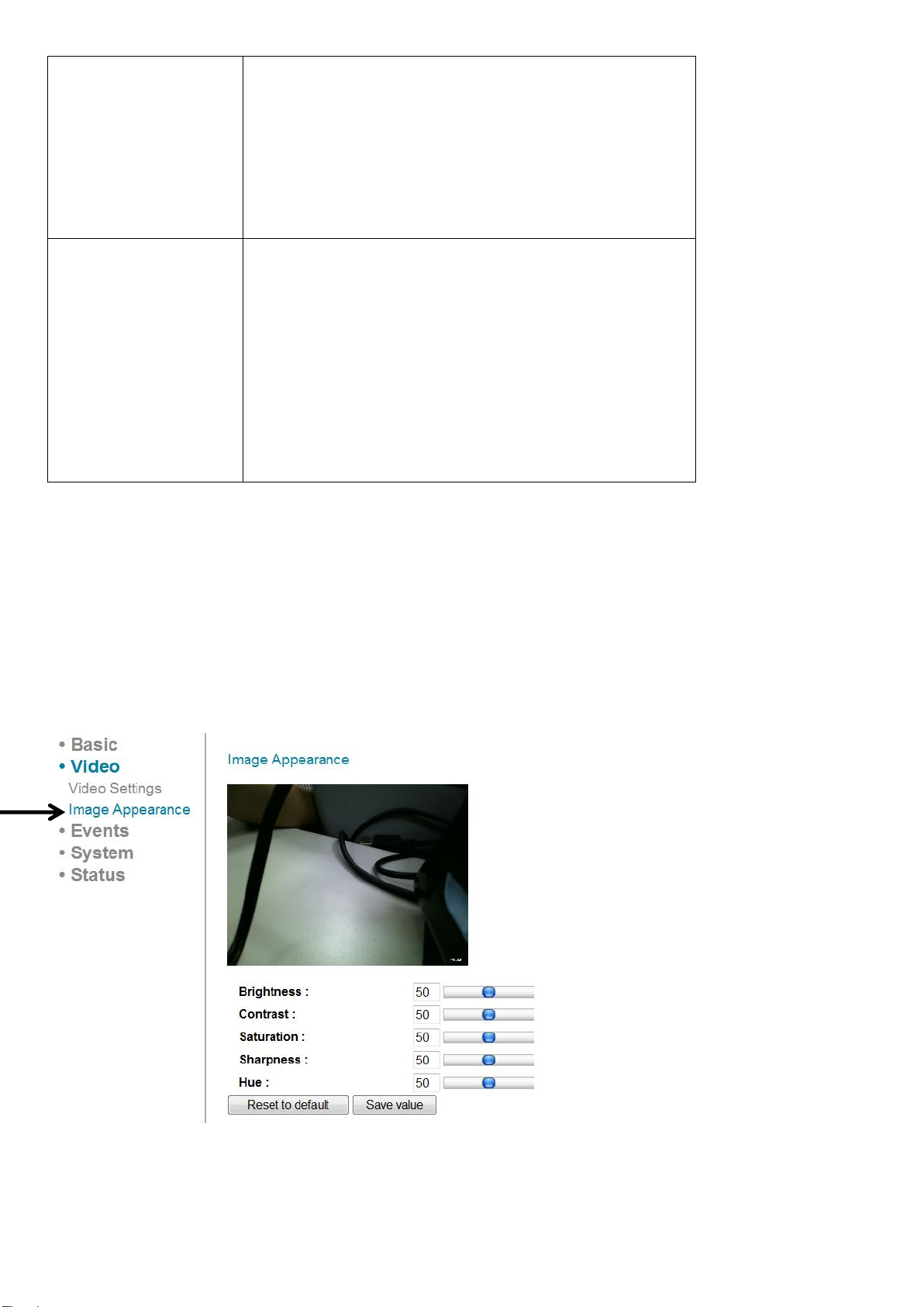
4.2 Image
You can change video appearance settings here.
The descriptions of these items are listed below:
38
Page 40

Item
Description
Brightness /
Contrast /
Saturation /
Sharpness /
Hue
Change the video’s appearance. Change
these parameters if you don’t like the
current appearance of the video.
Click and drag the blue lever to change the
value.
Reset to default
Click this button to reset all settings back
to the default value (50).
Save value
Save changes you made.
39
Page 41
Item
Description
Motion
Detection enable
Select ‘Enable’ to enable motion detection,
or ‘Disable’ to disable it.
Motion
Detection
Interval
Select the time interval this network
camera detects motion.
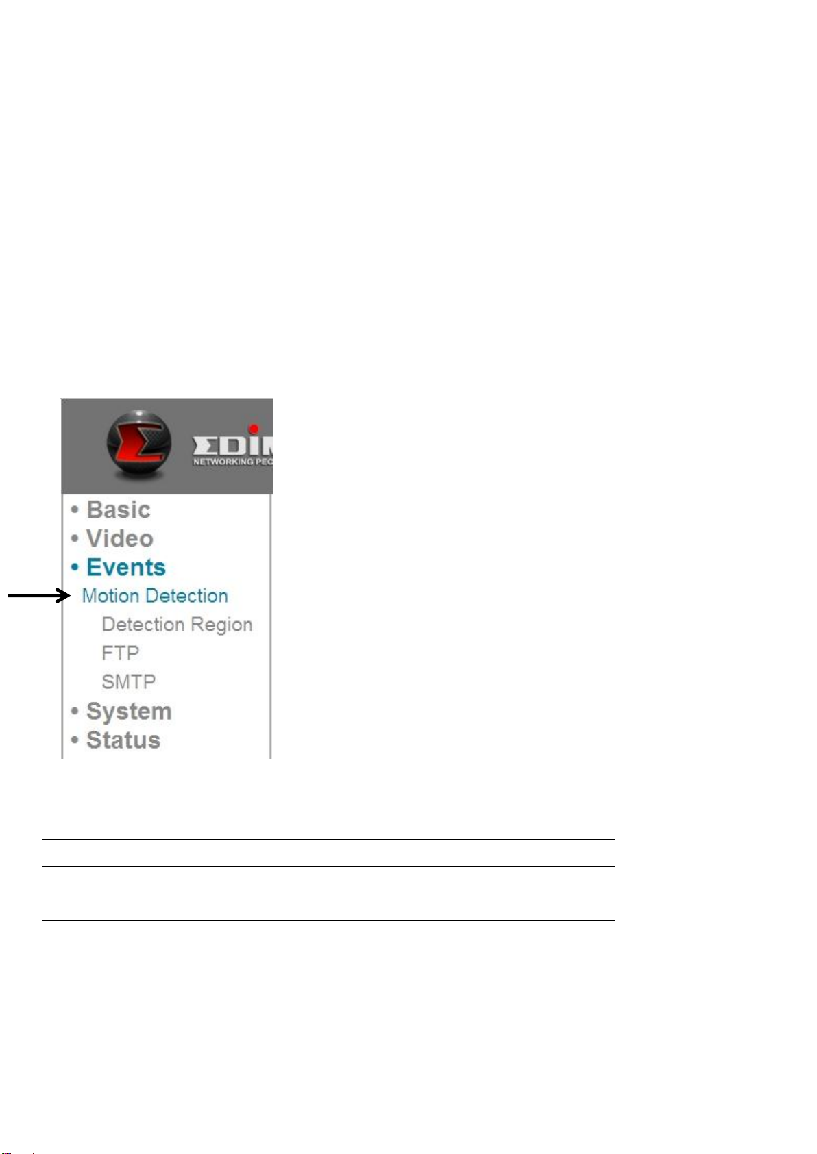
To detect minor motions, select a shorter
Chapter V: Event Configuration
This network camera is able to detect motion. You can use this feature to use
this network camera as a security alarm, and send the image to you by email or
upload the image to an FTP server when there’s motion.
5.1 Motion Detection Setup
You can enable or disable motion detection settings here.
The descriptions of these items are listed below:
40
Page 42

time; to ignore minor motions, select a
longer time.
Send snapshot to
E-Mail
Select ‘Enable’ to send a snapshot picture
to a designated email recipient; select
‘Disable’ to disable this feature.
Send snapshot to
FTP
Select ‘Enable’ to upload a snapshot
picture to a designated FTP server; select
‘Disable’ to disable this feature.
Click the ‘Apply’ button to save changes you made.
5.1.1 Detection Region
You can set up the area in the video where the network camera should detect
changes in video (motion). Motions outside of the detection region will be
ignored by the network camera. This will help you minimize the chances of false
alarms.
When you select this setup page, you’ll see the following setup page:
41
Page 43
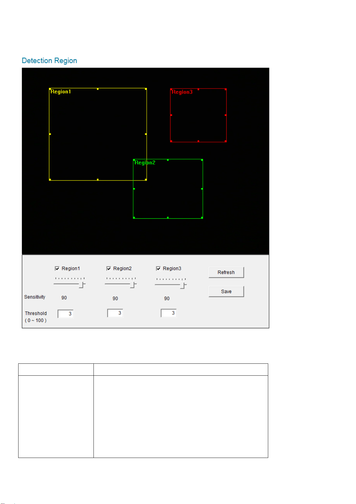
(The setup page’s video view window is intentionally set to black so you can see
Item
Description
Region 1 /
Region 2 /
Region 3
Check the box to enable this motion
detection region. A rectangle will appear
on the video view when it’s checked
(enabled).
To change the size of motion detection
area:
the 3 motion detection regions clearly).
The descriptions of these items are listed below:
42
Page 44

Move the mouse to a corner or the middle
of an edge of the motion detection
rectangle, and click and drag the mouse.
To move the motion detection area:
Position the mouse within the motion
detection area, and click and drag the
mouse.
Sensitivity
Change the sensitivity of motion detection.
Set to a higher value (right) and the
network camera will trigger the alarm
when there are only small changes in
video. If you find that the network camera
sends emails or uploads pictures to FTP
too frequently, and there’s nothing
happening in the snapshot, you can set this
to a lower value.
Threshold
Set the motion detection threshold here
(input number 0 to 100). A higher value
means the network camera will only
trigger an alarm when the object in the
motion detection area is really big.
Refresh
Refresh the reference picture.
Save
Save changes you made in this page.
43
Page 45

5.1.2 FTP
Item
Description
FTP Server
Input the IP address or host name of the
FTP server.
You can upload a snapshot picture to an FTP server when motion is detected by
this network camera.
When you select this setup page, you’ll see the following setup page:
The descriptions of these items are listed below:
44
Page 46

User Name
Input the user name required by the FTP
server.
Password
Input the password of the FTP server.
Port
Input the port number of the FTP server,
this should an integer between 1 and
65535.
Please don’t change this value unless so
instructed by the FTP server’s
administrator.
Path
Input the path (folder) you wish to save
snapshot files to on the FTP server. If you
don’t want to specify a folder, you can
leave this field blank, and snapshot files
will be saved in the default root folder on
the FTP server.
Passive mode
Default setting is ‘Enable’ (use passive
mode). If the FTP server you’re going to
use does not support passive mode (using
active mode), select ‘Disable’ here.
Click the ‘Apply’ button to save changes you made. You can also click the ‘Send a
test file’ button to upload a test file to the FTP server, and a message box will
appear to indicate if the FTP upload was successful, so you can determine if the
parameters you set in this page are correct.
45
Page 47

5.1.3 SMTP
Item
Description
You can send a snapshot picture by email when motion is detected by this
network camera.
When you select this setup page, you’ll see the following setup page:
The descriptions of these items are listed below:
46
Page 48

Public Server
If you’re using Hotmail, Yahoo mail, or
Google mail, select the appropriate item
from the dropdown menu, and the
network camera will fill in the SMTP server
address and port number for you
automatically.
SMTP Server
Input the host name or IP address of the
SMTP server. This information is usually
provided by your ISP.
SMTP Port
Input the SMTP port number here. Most
SMTP servers use port number 25, while
some SMTP servers use encrypted
connections with a port number of 465.
Consult your mail server administrator
when in doubt.
Recipient E-Mail
Address
Input the email recipient’s email address
here.
Sender E-Mail
Address
Input an email address here, which will be
used as the email sender’s address. This
will help you to identify the email sent by
this network camera, and will help you to
prevent problems caused by spam filters.
SSL/TLS
Select ‘SSL or TLS’ when your SMTP server
requires encryption.
Consult your mail server administrator
when in doubt.
SMTP
Authentication
Select ‘Enable’ when your SMTP server
requires authentication.
Consult your mail server administrator
when in doubt.
Account
Input the SMTP account name when your
SMTP server requires authentication.
Password
Input the password used for SMTP server
authentication.
47
Page 49

Click the ‘Apply’ button to save changes you made. You can also click ‘Send a
test E-mail’ button to send a test email to the SMTP server, and a message box
will appear to indicate if the email was successful, so you can determine if the
parameters you set in this page are correct.
48
Page 50
Chapter VI: System Configuration
Item
Description
IPCamera Name
Set the name of the network camera. It’s
recommended to use a meaningful name
which can describe the location or purpose
of the camera. This will help you to identify
the network camera when you have more
than one.
Administrator
Password
Input a new administrator’s password here
if you want to change it.
Confirm
Password
Input the new administrator’s password
here again for confirmation.
LED Indication
For security reasons, you can disable the
LED lights in front of the network camera
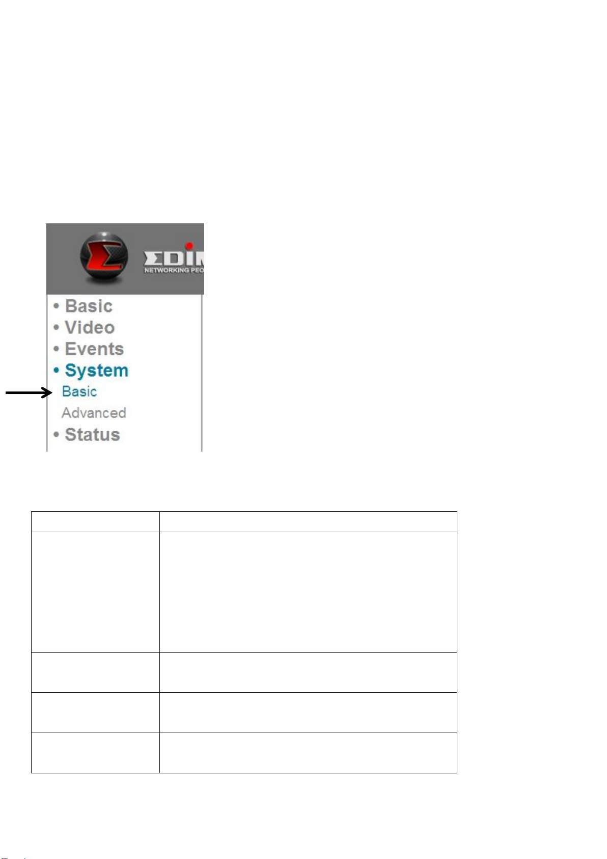
You can configure the basic system settings in this setup page, or backup /
restore system configurations.
6.1 Basic Settings
You can set the camera’s name and password here. You can also change the
behavior of LED lights.
The descriptions of these items are listed below:
49
Page 51

by select ‘off’ here, so other people can’t
tell if the network camera is active.
Item
Description
Firmware
Filename
You can improve the functionality of this
network camera by uploading a new
firmware file when available.
Please download new firmware files from
our website, and save it to your
computer’s hard disk. Then, click the
‘Browse’ button to select the file on your
hard disk, and click the ‘Apply’ button to
upload the firmware to Network camera.
Backup Config
Click the ‘Apply’ button to download the
Click the ‘Apply’ button to save changes you made.
6.2 Advanced Settings
You can save or restore the network camera’s configuration file here. You can
also reboot the network camera remotely here.
The descriptions of these items are listed below:
50
Page 52

current configurations as a file and save it
on your computer’s hard drive.
Restore Config
Click the ‘Browse’ button to select a
previously-saved configuration file on your
computer’s hard drive, and then click
‘Apply’ to upload the configuration file.
Reboot Now
Click this button to reboot the network
camera. This function is useful when you
think the network camera is not working
properly.
Reset to default
Reset the network camera’s settings back
to default values. There are 2 options:
1) Keep Network Setting: Reset all settings
back to default value, but keep network
settings. You can still use the same IP
address to connect to the network
camera.
2) Factory Default: Reset all settings,
include network settings. Please
reconnect to the network camera by its
default IP address 192.168.2.3, or run
EdiView Finder again to find its IP.
Click ‘Apply’ to reset. You can also press
and hold the ‘WPS / Reset’ button for
more than 10 seconds to reset the
network camera’s settings to default
values.
51
Page 53

Chapter VII: System Status
You can view the status of this network camera, which is helpful when you need
to do detailed configuration, or debug.
7.1 System Information
You can see system-wide information of this network camera here.
52
Page 54

A system information summary page will appear, similar to this:
53
Page 55
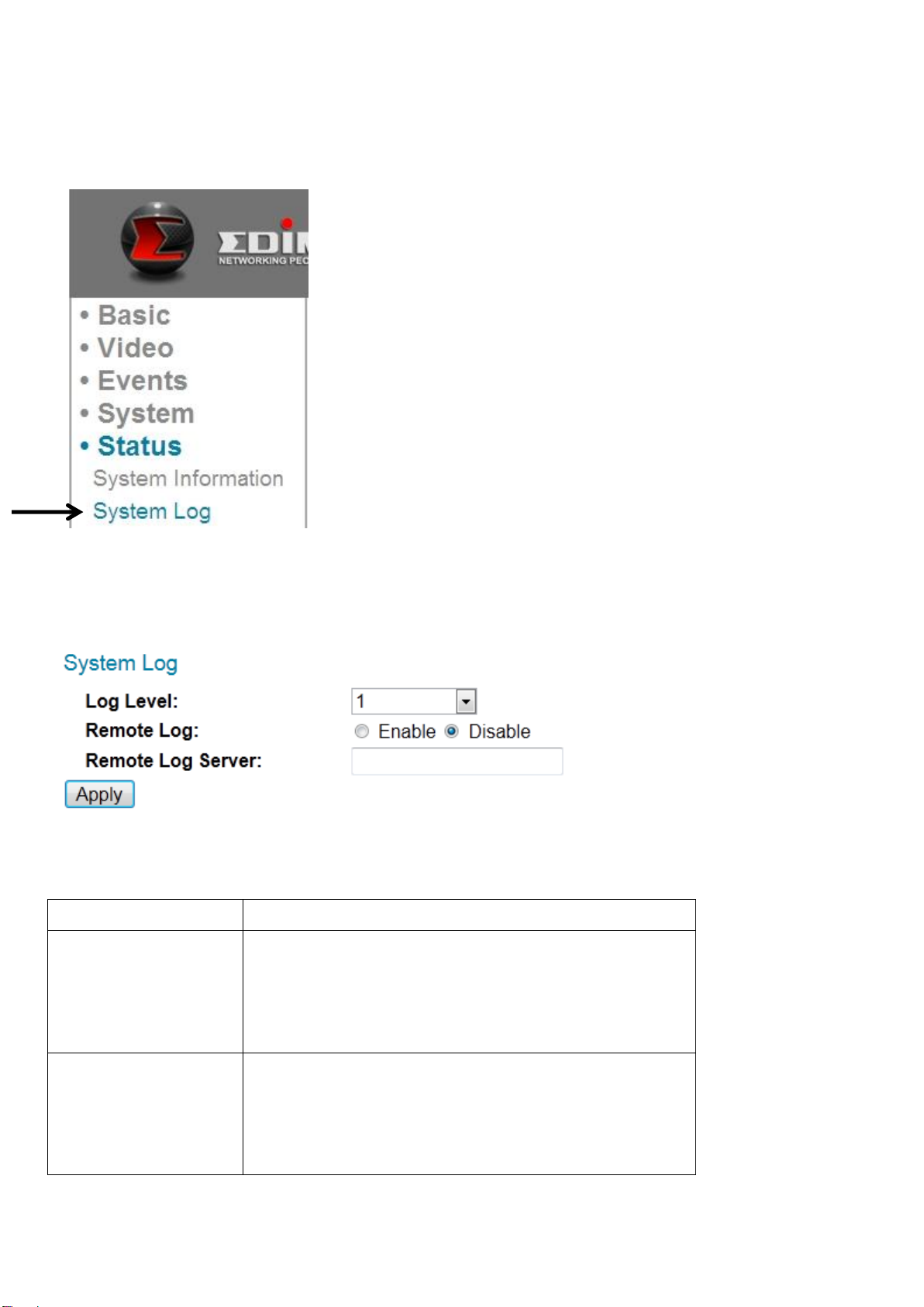
7.2 System Log
Item
Description
Log Level
Select the log level from the dropdown list.
Select 0 and the network camera will only
log very important information, or select 4
to log everything.
Remote Log
This Network camera can send log
information to a remote server for
archiving. Select ‘Enable’ to enable this
function.
The network camera’s usage and actions will be displayed here.
The system log will appear here, you can use the scroll bar to view logs, with
some adjustable parameters:
The descriptions of these items are listed below:
54
Page 56

This network camera supports syslog log
servers.
Remote Log
Server
Input the IP address or host name of the
log server you wish to use.
Click the ‘Apply’ button to save changes you made.
55
Page 57

Chapter VIII: Advanced Operations
In this chapter, you’ll learn how to apply for a DYNDNS account to use with this
network camera when you don’t have a fixed IP address, and view the video of
this network camera on your iPhone.
8.1 Applying for a DynDNS Account
If your ISP issues you with an IP address that is not fixed, please follow the
following instructions to apply for a free DynDNS account, to get a host name
that is dynamically mapped to your current IP address.
1. Launch your web browser and navigate to http://www.dyndns.org
2. Click ‘Sign In’ (located at upper-right corner of dyndns.org’s webpage)
56
Page 58
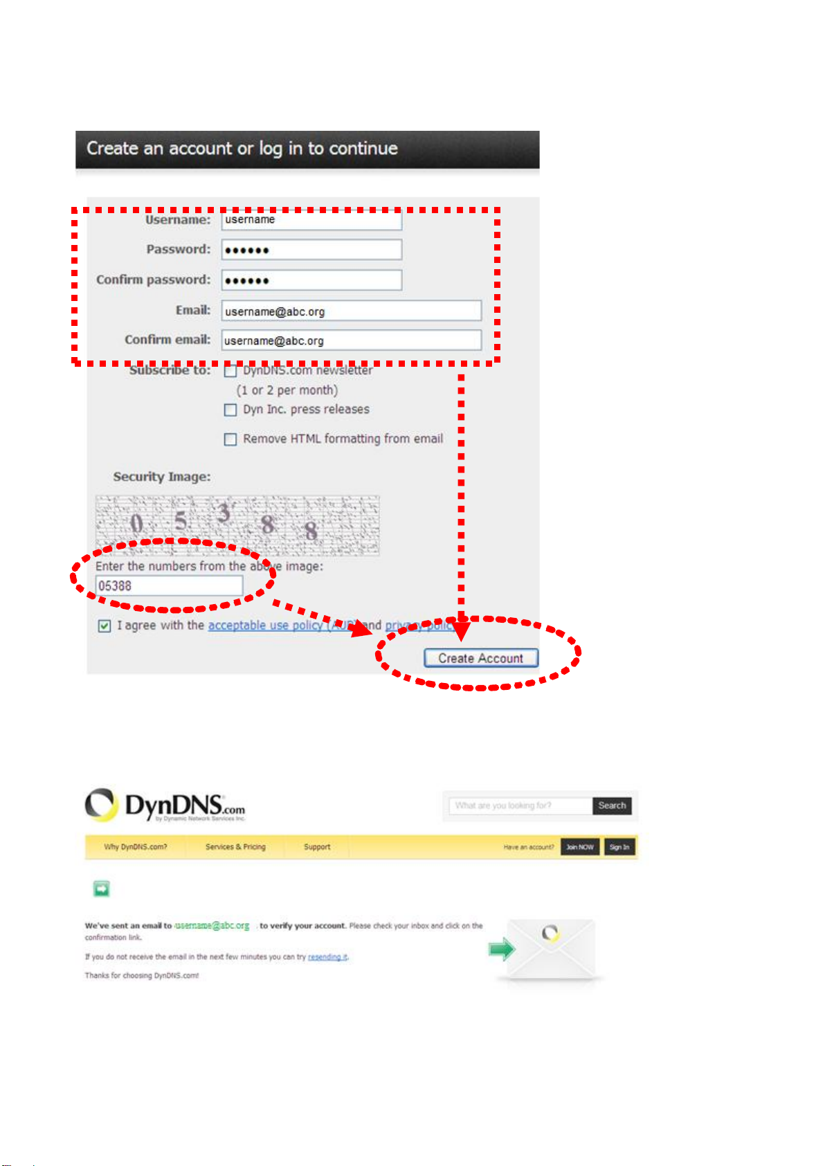
3. Fill in all fields that appear in this menu, and click the ‘Create Account’ button
to create a new account. You’ll be prompted if the account you selected is
not available.
4. When you see this image, you’ll receive an e-mail confirmation at the e-mail
box you registered with dyndns.org.
57
Page 59
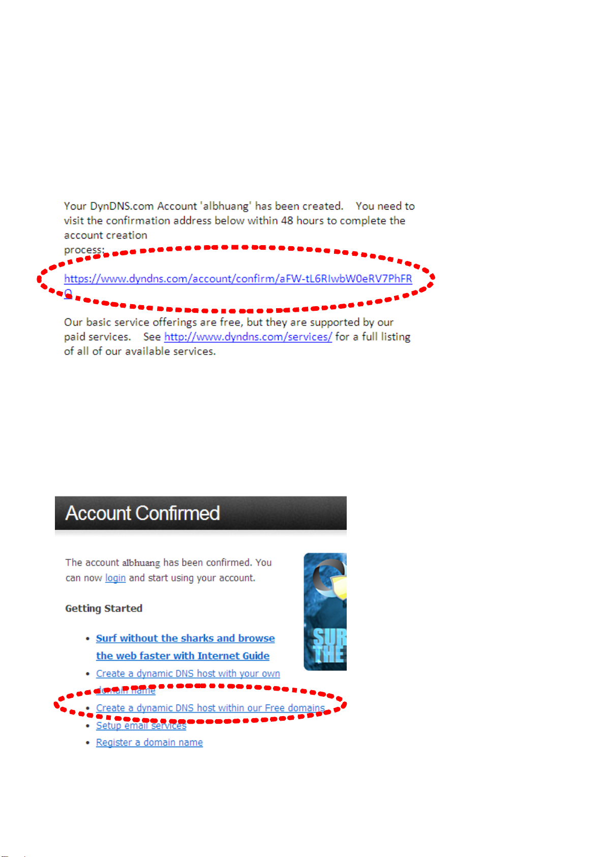
5. Check your e-mail box and you should be able to see the confirmation e-mail.
Click the link to connect to the dyndns.org website and complete the
registration procedure. If you didn’t get the mail, please re-check the e-mail
address, or click the ‘resending it’ link in last step.
Also, if nothing happen after you click the link in the message, please copy
the link text and paste it into your web browser’s address bar.
6. When you see the ‘Account Confirmed’ webpage, it indicates your
dyndns.org account has been confirmed and activated. Now you can click
‘Create a dynamic DNS host within our Free domains’ to continue.
58
Page 60

7. Click the ‘Create Hostname’ button.
8. In this page:
Input the hostname of your choice in the ‘Hostname’ field,
Select a domain name from the dropdown menu,
Select ‘Host with IP address’ for ‘Service Type’,
Input the current IP address in the ‘IP Address’ field (or click the link below to
use the detected IP address to fill this field’.
59
Page 61

9. Click ‘Add to cart’ continue.
10. Click ‘Next’ to continue.
60
Page 62
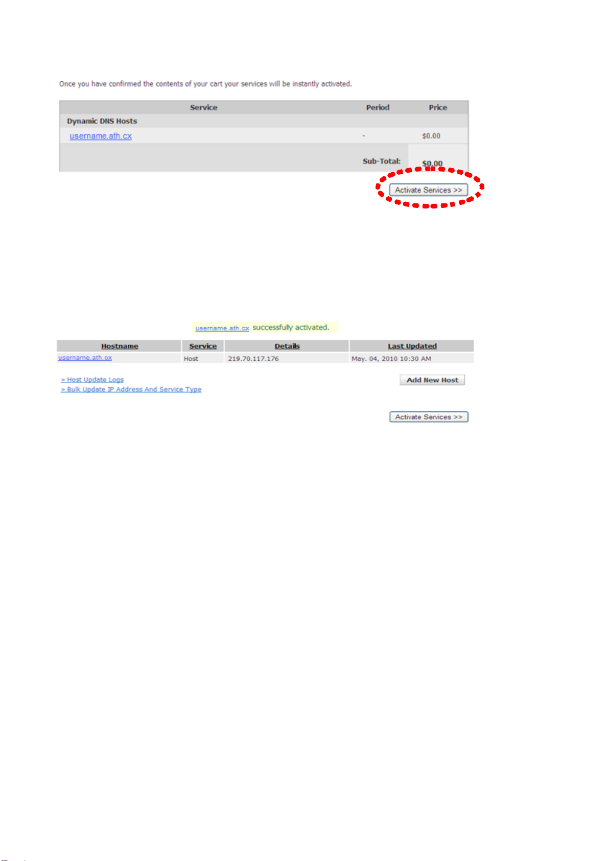
11. Click ‘Activate Services’ to continue.
12. When you see this message, it indicates your free dyndns.org hostname
mapping service has been activated. You can go to chapter 2-2-3 to use your
dyndns.org username, password, and hostname + domain name to locate
your network camera on the Internet even you’re using dynamic IP addresses!
8.2 Applying for a Free no-ip.com Account
It’s very likely your IP address (the Internet location) keeps changing every few
hours or every day depending on your ISP’s policy. Therefore, as shown in the
following figure, you may have been assigned with an IP address, “61.61.61.1”
hours ago, but now you have a new IP address, “72.72.72.1”. This means the
router at “My home”, which could be found at http://61.61.61.1 over the
Internet, is no longer available after a few hours. To find the new location (IP
address) of the router at “My home” over the Internet, you need to log in to the
router, checking the new IP address. However, this is not always a workable
solution.
To overcome this problem, an Internet service called NO-IP DNS is designed to
help you trace the log of the changing IP address linked to a website address
61
Page 63

(URL). As shown in the following figure, one PC called “DNS server” keeps
revising the record “your-name.no-ip.org vs 61.61.61.1” in its internal DNS
directory. If you enter http://your-name.no-ip.org into an iPhone you can find
the 2 network cameras at “My home”.
The following are steps to apply for an account named “your-name.no-ip.org” at
http://www.no-ip.com and how this account is configured in an Edimax router.
Note: http://www.no-ip.com is not a branch or affiliate of Edimax. No
commercial relation is involved between these 2 companies. The related service
offered by http://www.no-ip.com is for free for a specific time. However,
Edimax does not guarantee this service.
First, go to http://www.no-ip.com and apply for an account.
Follow these steps:
Click the “Create Account” link.
62
Page 64
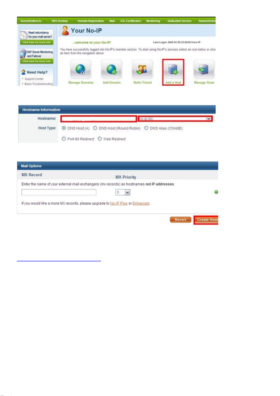
Click “Add a Host”.
Fill in the host name and select a host from the drop down list.
Click “Create Host” to complete the process.
Now, you could locate your home network camera using
http://your-name.no-ip.org.
63
Page 65

Chapter IX: Windows Surveillance Utility
Besides using web browser to operate this network camera, you can also use
the Windows utility, which provides faster access to all functions of this network
camera.
9.1 Installing the Network Camera Administration Software
1. Double-click the Setup_Viewer_xxx file to start installation.
64
Page 66

2. Click ‘Next’ to continue.
3. You can uncheck the boxes here if you don’t want to create a desktop / quick
launch icon, and click ‘Next’ to continue.
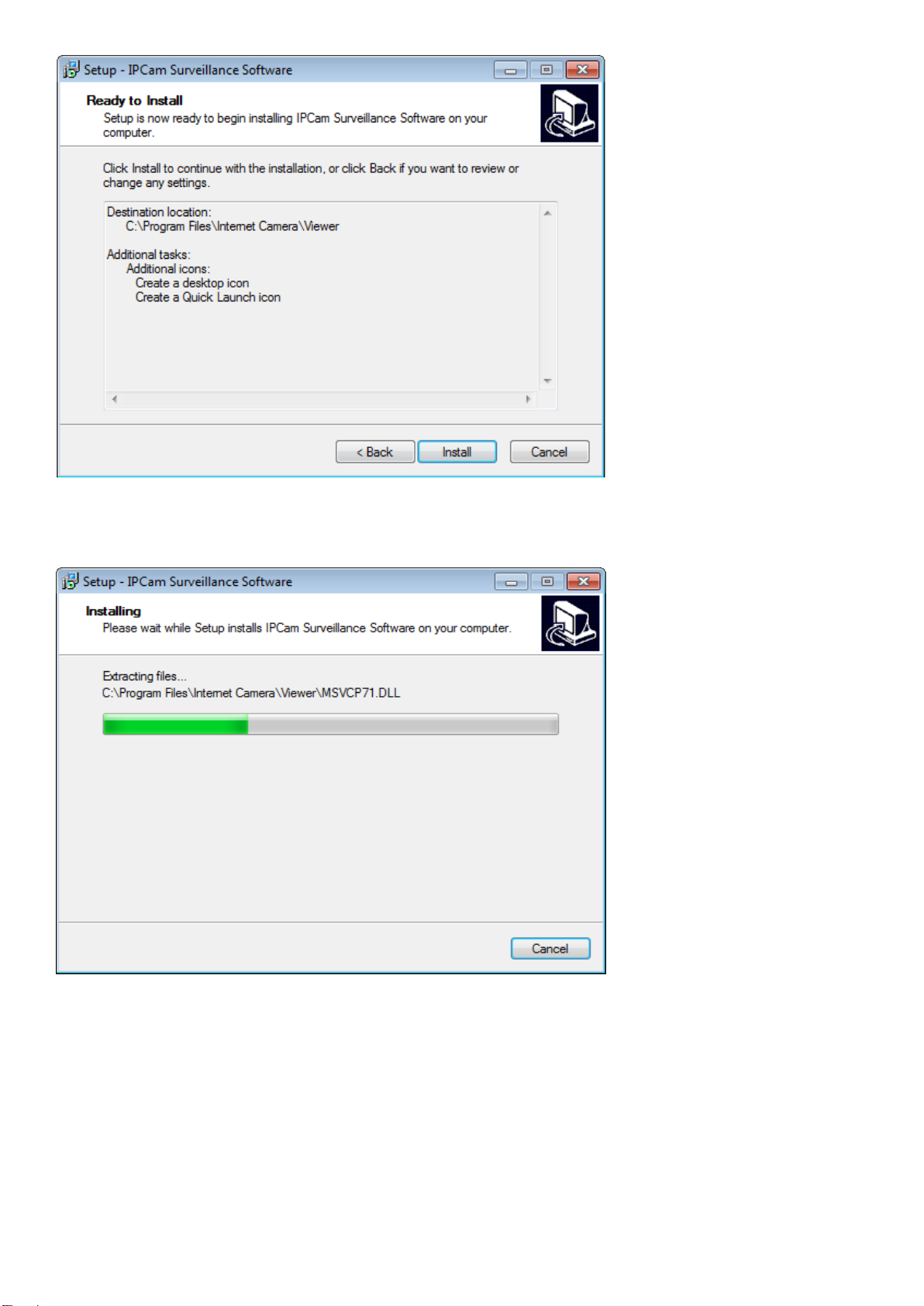
4. Please check if everything’s correct here. If you want to change any settings,
click ‘Back’ to go back to the previous page, or click ‘Install’ to start installation.
65
Page 67
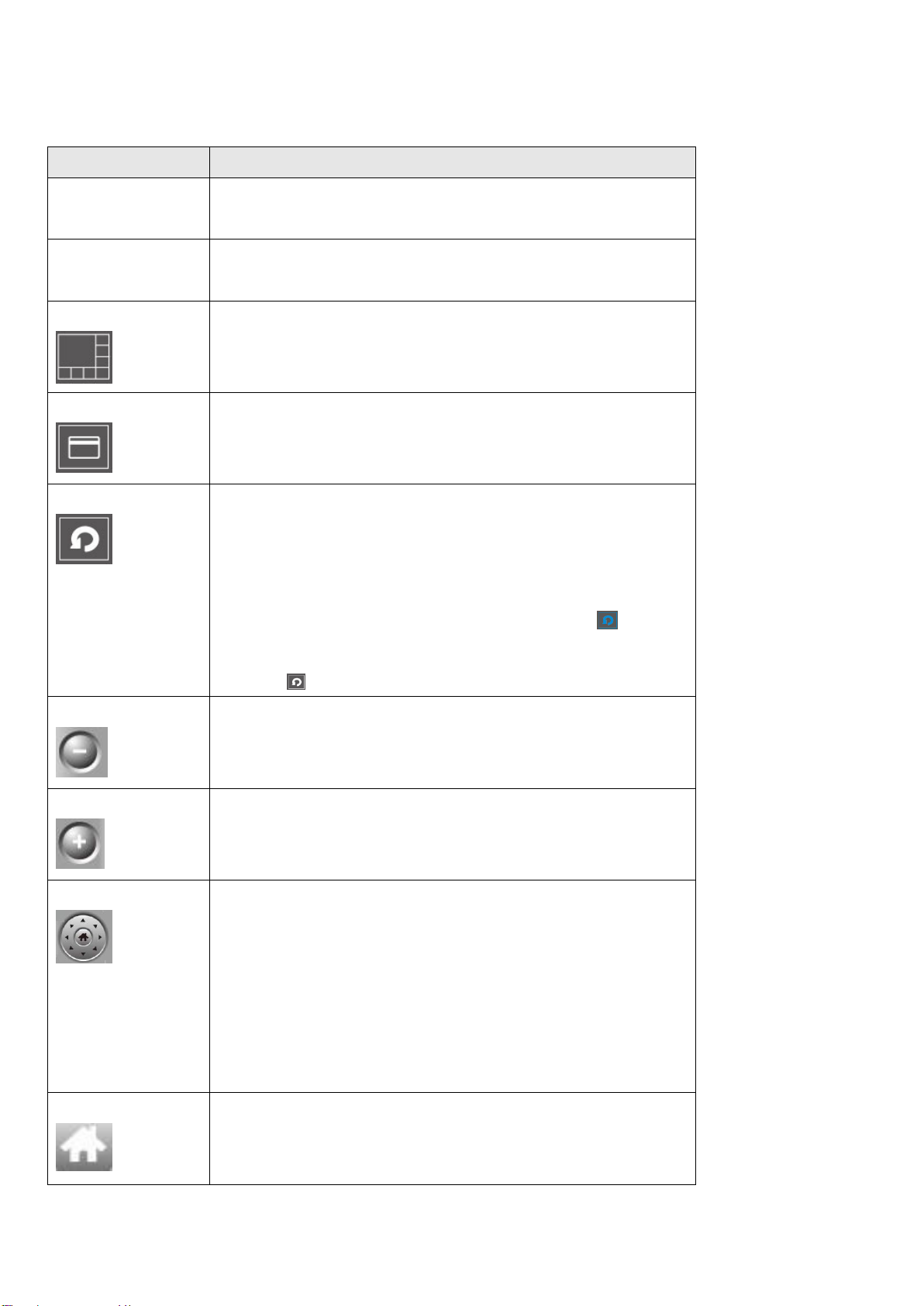
5. Installation procedures take a few seconds to a few minutes to complete,
please be patient.
6. Installation is complete when you see this message. You can click ‘Finish’ to
finish installation procedures and launch the utility, or uncheck the ‘Launch
IPCam Surveillance Software’ box before you click the ‘Finish’ button if you
don’t want to launch the software after installation is complete.
66
Page 68

67
Page 69

9.2 Using the Network Camera Surveillance Software
Before you start:
The network camera surveillance software will only work when your
monitor’s resolution is ‘1024 x 768’. Please change the resolution
before you use the network camera surveillance software, or it won’t
start.
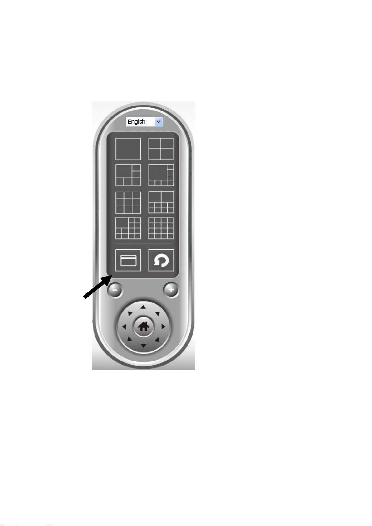
Language
Display
layout
Full screen /
Scan
Zoom Out /
Zoom In
PTZ Control /
Home
Recording / System configure
Playback / Snap shot
Close window (stop surveillance) /
Minimize window
Video display area
Message display
box
You can select the ‘IPCam Surveillance Software’ icon from your desktop, quick
launch bar, or start menu to start the network camera surveillance software.
Here are descriptions for all components of the network camera surveillance
software:
68
Page 70
You can put the mouse cursor on a certain component and see its button name.
Item
Description
Video display
area
The image of all connected cameras will be
displayed here.
Language
Select a language from this dropdown menu
to change the display language.
Display layout
Change camera image display layout (Click a
layout icon to change camera display layout).
There are 8 kinds of display layouts available.
Full screen
Click this button to switch to full screen mode
(only display all camera’s image), press ‘ESC’
key to quit full screen mode.
Scan
Click this button and the network camera
surveillance software will switch through the
images of all connected camera automatically.
Click this button once to activate the scan
function (scan icon will become blue ), click
again to stop scanning (scan icon will become
white ).
Zoom out
Zoom out (To see more objects).
This function is only available for supported
cameras.
Zoom In
Zoom in (Too see more details).
This function is only available for supported
cameras.
PTZ control
There are 8 directions in the Pan Tilt Zoom
(PTZ) control ring. If the camera you connect
to supports PTZ, you can use the PTZ control
ring to change the direction that the camera
faces.
This function is only available for supported
cameras.
Home
Click this button to return the camera to
‘Home’ (default) position.
This function is only available for supported
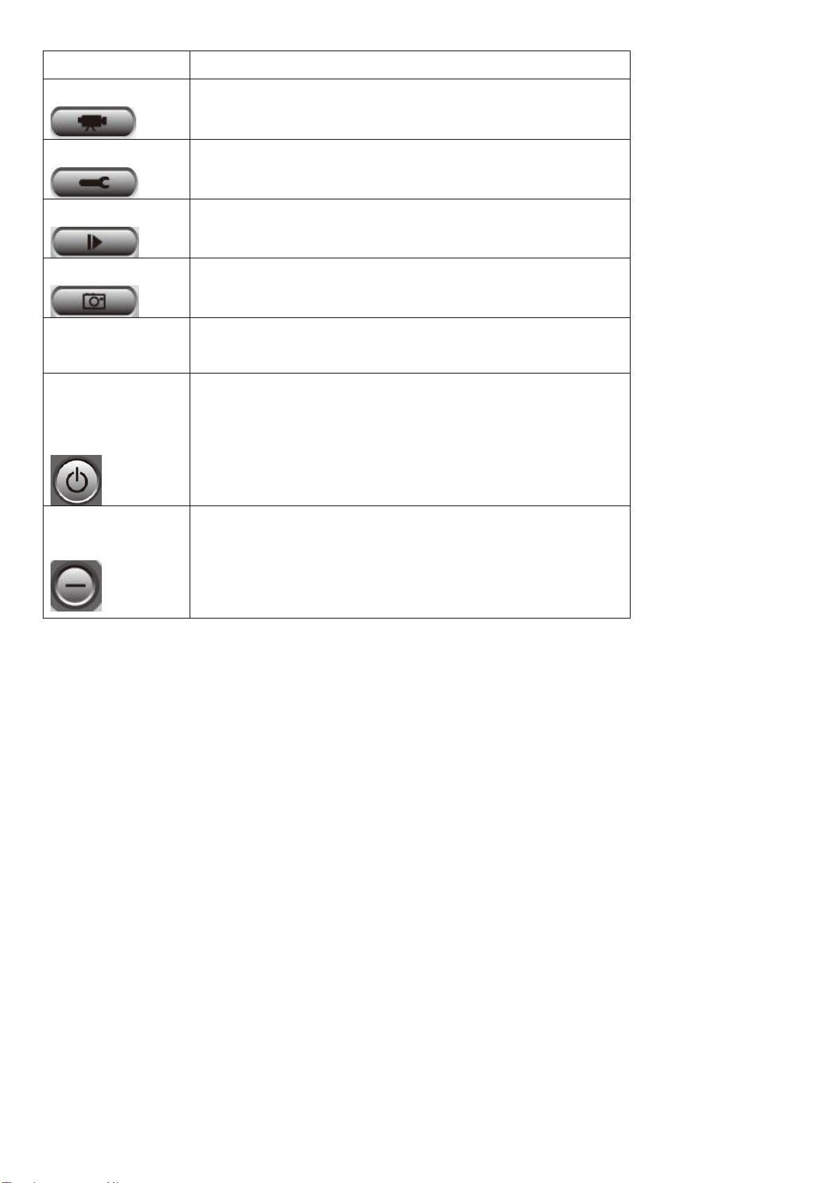
For detailed descriptions of all buttons:
69
Page 71
cameras.
Recording
Start video recording.
Configure
Software / camera configuration.
Playback
Play back a recorded video file.
Snapshot
Take a snapshot of current the camera image.
Message
display
Displays all system messages.
Close window
(stop
surveillance)
Terminates network camera surveillance
software.
Minimize
window
Minimizes network camera surveillance
software window.
70
Page 72
9.3 Configuring the Network Camera Surveillance Software
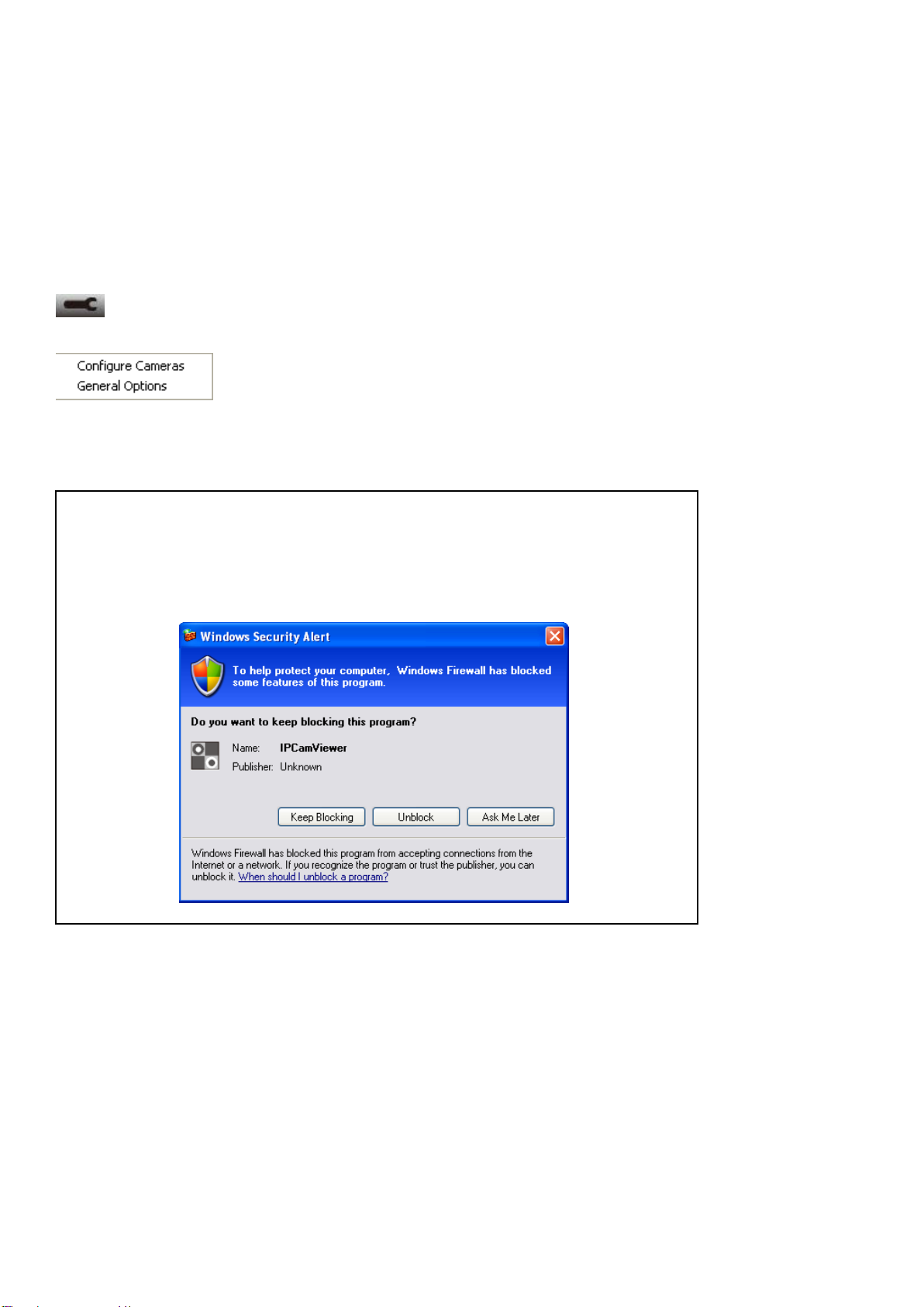
Note: If you’re prompted by a Windows security alert which asks you
if you want to block ‘IPCamViewer’ program, please click the
‘Unblock’ button, otherwise the network camera surveillance software
will not be able to function correctly.
9.3.1 Camera Configuration
Before you use this network camera surveillance software, you must configure
the camera(s) you wish to connect. Please click the ‘System configure’ button
and a popup menu will appear:
Please select ‘Configure Cameras’ to configure cameras:
71
Page 73

9.3.1.1 “Camera” Settings
Item
Description
Channel
Select the channel number you wish to set.
Camera
Search
All cameras found on your local network will
be displayed in the ‘Camera Search’ box.
Select
Select a camera listed in the ‘Camera Search’
box, and click the ‘Select’ button to fill all
parameters of the selected camera in every
camera configuration field.
Refresh
Rescan all cameras on your local network. Use
this if you didn’t see the camera you expected
in the ‘Camera Search’ box, or new cameras
have been added to your local network after
the last scan.
In this tab you can configure all the cameras you wish to connect to. Up to 16
cameras can be connected simultaneously:
Here are the descriptions of all settings:
72
Page 74

Name*
Input the name of the camera here. The
default name is the first 6 bytes of the
camera’s MAC address; you can change the
name of the camera so you can remember the
camera’s location or purpose easily.
Model
Displays the model of the selected camera,
this field cannot be changed.
IP*
Input the IP address of the camera.
Username*
Input the user name of the camera.
Web Port*
Input the web port of the camera. By default
it’s ‘80’.
Password
Input the password of the camera. Default
password is ‘1234’. You should change the
entered password if you changed the
password of the selected camera.
Video
Format**
Select the video encoding format of this
camera (MJPEG or MPEG4).
Reset
Clear all fields in the ‘Camera Configuration’
section.
OK
Save settings in this tab.
Cancel
Discard all settings in this tab.
*: It’s recommended to use ‘Select’ button to fill the content of this field.
**: Only available for cameras support this function.
After you’ve set all channels you wish to set, click ‘OK’ to save settings, and if
everything’s correct, you’ll see the camera’s image in the network camera
surveillance software’s main screen:
73
Page 75
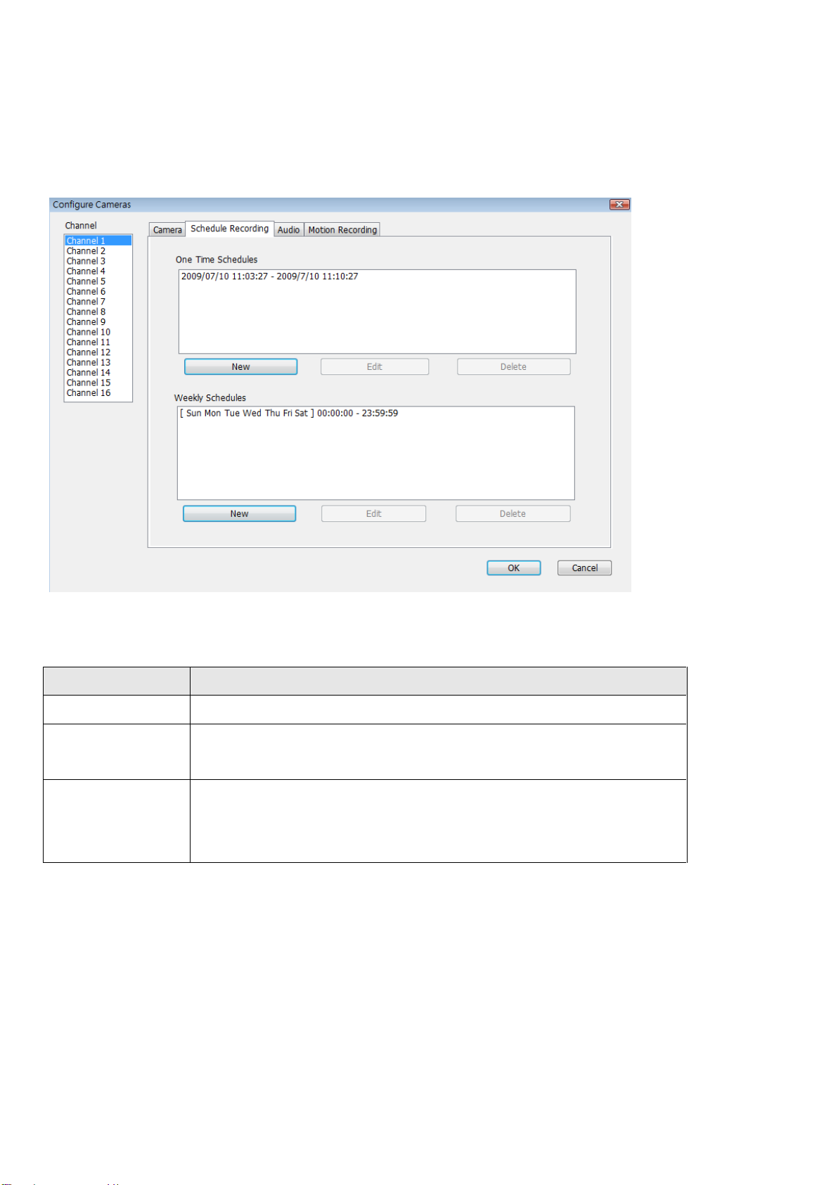
9.3.1.2 Scheduled Recording
Item
Description
Channel
Select the channel number you wish to set.
One Time
Schedules
You can specify the one-time schedule for a selected
camera; this schedule will be executed once only.
New
(One Time
Schedules)
Click this button and a new window will appear:
In this tab, you can setup scheduled video recording, so you can record the
video captured by all cameras you have according to a pre-defined schedule.
Here are the descriptions of all settings:
74
Page 76

Please specify the time duration of this one-time
schedule (the date and time of ‘From’ and ‘To’),
then click ‘OK’ to save settings.
Please note you must set a schedule that will
happen in the future, you cannot set a schedule in
the past.
Edit
You can modify a scheduled recording item. Select a
schedule in ‘One Time Schedules’ list, and click the
‘Edit’ button to edit the start and end time of this
schedule.
Delete
Delete a selected schedule item.
New
(Weekly
Schedules)
Click this button and a new window will appear:
You can define the recording schedule that will be
executed at the specified time of certain weekday(s)
in a week. Please check all weekdays that apply, and
set the start time in the ‘From’ field. You can set the
75
Page 77

duration of video recording in the ‘Period’ field
(format is HH:MM:SS), and the end time will be
calculated automatically and displayed in the ‘To’
field. You can also click the ‘All Time Record’ button
to define a recording schedule that will be executed
every weekday, from 12:00:00AM to 11:59:59PM.
Click ‘OK’ to save changes.
Edit
You can modify a scheduled recording item. Select a
schedule in the ‘One Time Schedules’ list, and click
the ‘Edit’ button to edit the start and end time of
this schedule.
Delete
Delete a selected schedule item.
OK
Save settings in this tab.
Cancel
Discard all settings in this tab.
76
Page 78

9.3.1.3 Audio
Item
Description
Channel
Select the channel number you wish to set.
Mute Audio
Check this box and the network camera
surveillance software will not play the audio
captured by this camera.
Record Video
Only
Check this box and the network camera
surveillance software will not record the audio
captured by this camera.
OK
Save settings in this tab.
Cancel
Discard all settings in this tab.
For cameras that support audio, you can use this tab to decide if you wish to
hear the audio captured by the selected camera.
Here are the descriptions of all settings:
77
Page 79

9.3.1.4 Motion-Triggered Recording
Item
Description
Channel
Select the channel number you wish to set.
Enable
Enable motion record function.
Disable
Disable motion record function.
Recording
Time
Select the time duration from the dropdown
menu, in seconds, that the camera will record
when a motion has been detected.
Invoke alarm
Send an alarm when a motion has been
WARNING: For applications where security is of high priority, it’s not
recommended to use this function, since some tiny changes you may
need to know about may not be enough to trigger the camera and the
camera will not start recording.
With this function activated, only motions captured by the camera will be
recorded, so you don’t have to waste hard disk storage space on images you
don’t need to pay attention to.
Here are the descriptions of all settings:
78
Page 80

when motion
is triggered
detected by the camera.
Send mail
when motion
is triggered
Send an email to a pre-defined address when
a motion has been detected by the camera.
OK
Save settings in this tab.
Cancel
Discard all settings in this tab.
79
Page 81
9.3.2 General Settings
You can set system-wide settings of this network camera surveillance software
in this menu.
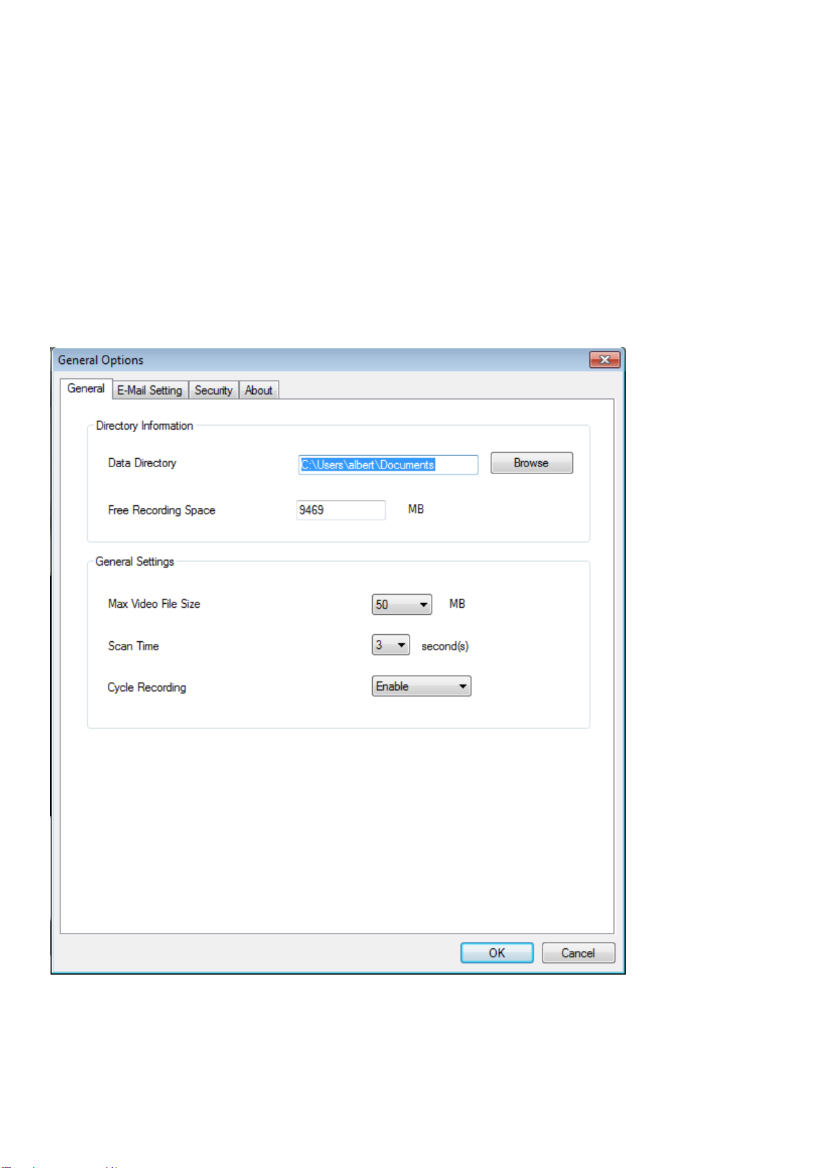
9.3.2.1 General
All general settings such as the file storage directory and recording spaces can
be set here.
Here are the descriptions of all settings:
80
Page 82

Item
Description
Data
Directory
Set the directory (folder) you wish to store the
recorded video and captured image. You can
click the ‘Browse’ button to pick a directory
on your hard disk.
Free
Recording
Space
Displays remaining storage space.
Max Video
File Size
Defines the maximum file size of every video
file. When the size of the file exceeds this
value, the network camera surveillance
software will open another file to record the
video.
Scan Time
Define the time period to pause between
every camera switch when you activate the
‘Scan’ function.
Cycle
Recording
You can decide the behavior when hard disk
space is full:
Disable: Do not overwrite recorded video files.
Enable: Overwrite recorded video files.
OK
Save settings in this tab.
Cancel
Discard all settings in this tab.
81
Page 83
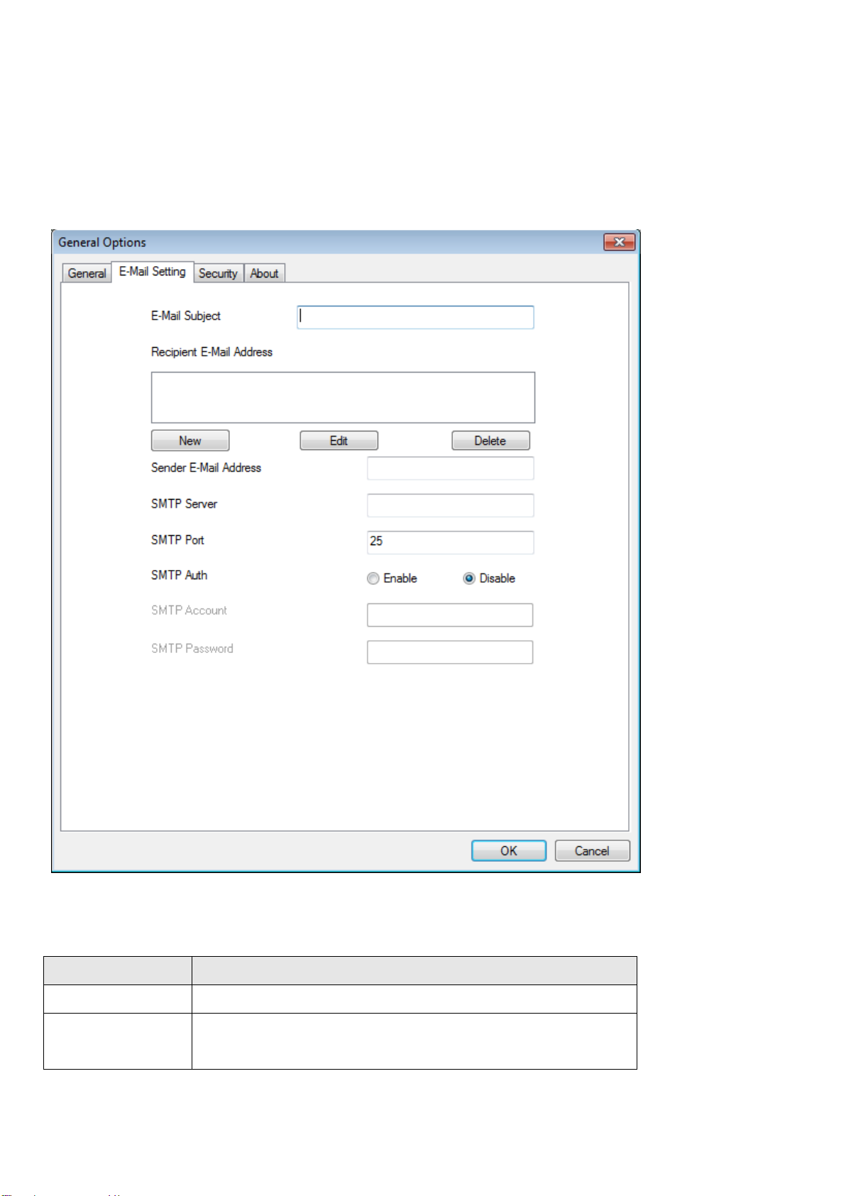
9.3.2.2 Email Setting
Item
Description
E-Mail Subject
Specify the subject of the sent email.
Recipient
E-Mail
Lists all email addresses you set.
If you want to use the motion detection function and wish to receive an email
that contains the image captured by the camera, please set up your email
related parameters here first.
Here are the descriptions of all settings:
82
Page 84

Address
New
Click this button and you’ll be prompted to
input the email address. Click ‘OK’ to save
changes.
Edit
Select an email address from the ‘Recipient
E-Mail Address’ box, and click ‘Edit’ to edit the
email address.
Delete
Delete the selected email address.
Sender E-Mail
Address
Specify the email address that will appear as
the sender.
SMTP Server
Specify the IP address or host name of the
SMTP server you wish to use. Most ISPs will
only allow their subscribers to use their SMTP
server, if you don’t know which SMTP server
you should use, please refer to the settings in
your email software or ask your ISP / network
administrator.
SMTP port
Specify the port number of the SMTP server
you wish to use here. By default (and the
setting of most of SMTP servers) it’s ‘25’.
SMTP Auth
Select ‘Enable’ if your SMTP server requires
authentication, select ‘Disable’ if it’s not
required. If you don’t know if your SMTP
server requires authentication, please refer to
the settings in your email software or ask your
ISP / network administrator.
SMTP
Account
Input the SMTP account (username) of your
SMTP server here. In most cases, it’s the same
as your POP3 username (the one you use to
83
Page 85

receive email). Please refer to the settings in
your email software or ask your ISP / network
administrator if you’re not sure about this.
SMTP
Password
Input the SMTP password of your SMTP server
here. In most cases, it’s the same as your
POP3 password (the one you use to receive
email). Please refer to the settings in your
email software or ask your ISP / network
administrator if you’re not sure about this.
OK
Save settings in this tab.
Cancel
Discard all settings in this tab.
9.3.2.3 Security
If you don’t want other people to access this network camera surveillance
software, you can set a password to protect it.
You’ll need to input the password every time you wish to use this network
camera surveillance software:
To set the password, please use the ‘Security’ tab in the ‘General Options’
menu:
84
Page 86
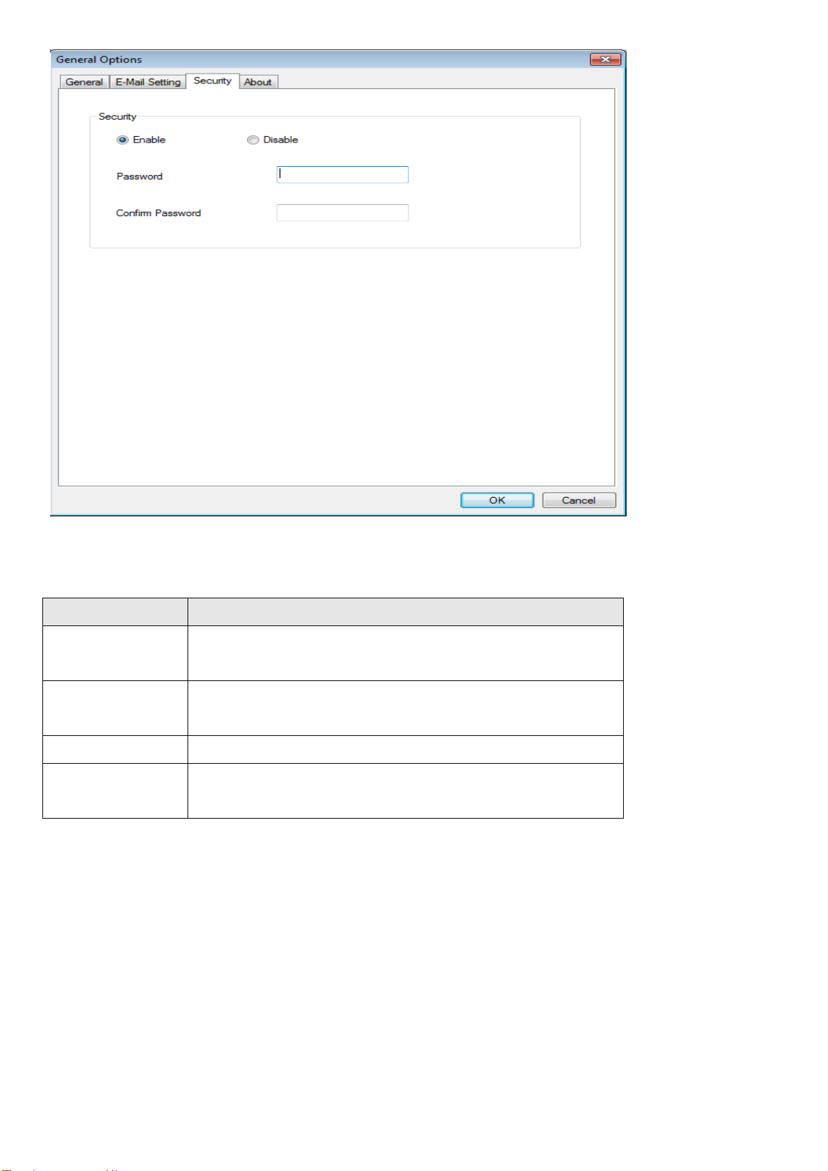
Item
Description
Enable
Requires password authentication when this
software starts.
Disable
Password authentication is not required when
this software starts.
Password
Input the password you wish to use here.
Confirm
Password
Input the password you wish to use here
again.
Here are the descriptions of all settings:
9.3.2.4 About
This tab shows the version number of the network camera surveillance software
you’re using.
85
Page 87

86
Page 88

9.4 Changing the Display Layout
Layout style
1: 1 Camera
only
Displays the video of 1 camera only.
Layout style
2: 4 Cameras
Displays the video of up to 4 cameras.
This network camera surveillance software provides 8 display layouts:
Every layout displays a different number of cameras in different arrangements,
you can click the icon that represents a specific layout, and the video display
area will change accordingly.
87
Page 89
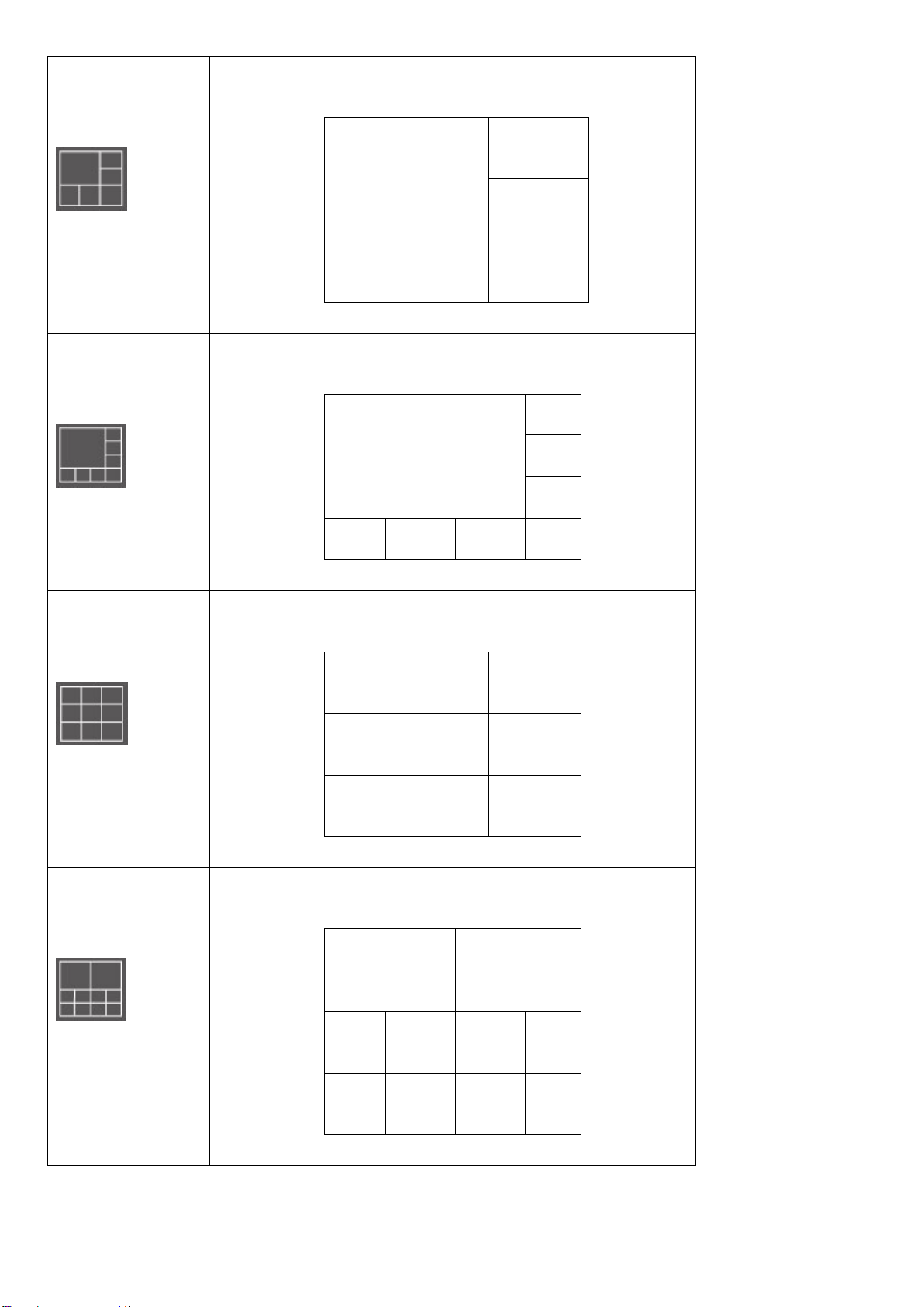
Layout style
3: 6 Cameras
Displays the video of up to 6 cameras.
Layout style
4: 8 Cameras
Displays the video of up to 8 cameras.
Layout style
5: 9 Cameras
Displays the video of up to 9 cameras.
Layout style
6: 10 Cameras
Displays the video of up to 10 cameras.
88
Page 90

Layout style
7: 13 Cameras
Displays the video of up to 13 cameras.
Layout style
8: 16 Cameras
Displays the video of up to 16 cameras.
89
Page 91
9.5 Full-Screen Mode
If you want to use all available space on your monitor to display the surveillance
image, you can click the ‘Full Screen’ button to switch the display mode to
full-screen mode.
To exit full-screen mode, press the ‘ESC’ key.
90
Page 92

9.6 Scan
NOTE: If a camera is configured but disconnected, it will still be
displayed in a scan sequence (you’ll see nothing and you’ll see the
text ‘Disconnected’ at the upper-left corner of the display image).
If you have more than one camera configured, and you wish to switch the
display image between cameras, you can click the ‘Scan’ button to switch
between all configured cameras.
Click the ‘Scan’ button once to activate the scan function (the scan icon will
become blue ), click again to stop scanning (the scan icon will become white
).
91
Page 93

9.7 Zoom-In/Zoom-Out
For cameras that support the zoom-in / zoom-out function, you can use this
function to see more objects within the camera’s view, or enlarge the image size
of a certain object to see it in detail.
Please select a camera in the video display area by clicking on its image, then
click the button to see more objects within the camera’s view, or click
to enlarge the image size of a certain object to see it in more detail (before
zooming in, you may need to use the PTZ buttons - described in the next section
- to find the object you wish to see in detail).
92
Page 94

9.8 PTZ
For cameras that support pan - tilt functions, you can change the direction that
the camera points to, to see different places that fall within the camera’s view.
Please select a camera in the video display area by clicking on its image, and
then click the directions you wish the camera to move to (total 8 directions
available). Click the ‘Home’ button ( ) to return to the camera’s home (default)
position.
93
Page 95

9.9 Snapshot
You can take a snapshot of a selected camera and save it to a ‘Snapshot’
sub-folder in a pre-defined data directory.
Click the snapshot button once to take a snapshot; you can take as many
snapshots as you want until the hard disk is full.
94
Page 96

9.10 Recording
You can start video recording a selected camera’s image by clicking the ‘Start
Recording’ button:
When recording starts, you’ll see a message displayed in the message display
box, such as ‘1/1 10:00:00, Camera 2 Start Manual’, which means camera 2
started recording manually on 1/1 at 10:00:00.
To stop recording, click the ‘Start Recording’ button again, and you’ll see a
message displayed in the message display box such as ‘1/1 10:00:00, Camera 2
Stop Manual’.
95
Page 97

9.11 Video Playback
You can playback all recorded video by clicking this button.
A new window will appear:
You have to search the video file before you can play it. There are two kinds of
video search: Time Search (search all videos file that fall within a specific period
of time) and Motion Search (search all videos recorded by the motion detection
function and fall within a specific period of time).
Please define the start and end date / time of the time period you wish to
search, and then click the ‘Search’ button (under ‘Time Search’ or ‘Motion
Search’). All found videos will be displayed, select the video you wish to play
and click the ‘Play’ button to playback.
96
Page 98

Chapter X: Accessing the Network Camera Remotely
10.1 Configuring the iOS Surveillance Software
Note: Make sure the device is connected to a Wi-Fi or 3G network before
launching the application. To install the EdiView Network Camera application on
an iOS device, do the following:
(1) Search for Edimax EdiView to download and install the application.
(2) When the application is successfully installed the EdiView icon is shown on
the screen.
(3) Launch EdiView by tapping the EdiView icon.
97
Page 99

Adding Network Cameras
There are two ways to add a network camera to the camera list:
Automatically scan and add available cameras located on the network.
Manually enter a network camera’s information.
Automatically Adding a camera
When the EdiView application is launched, it automatically searches the LAN for
all Edimax network cameras.
98
Page 100
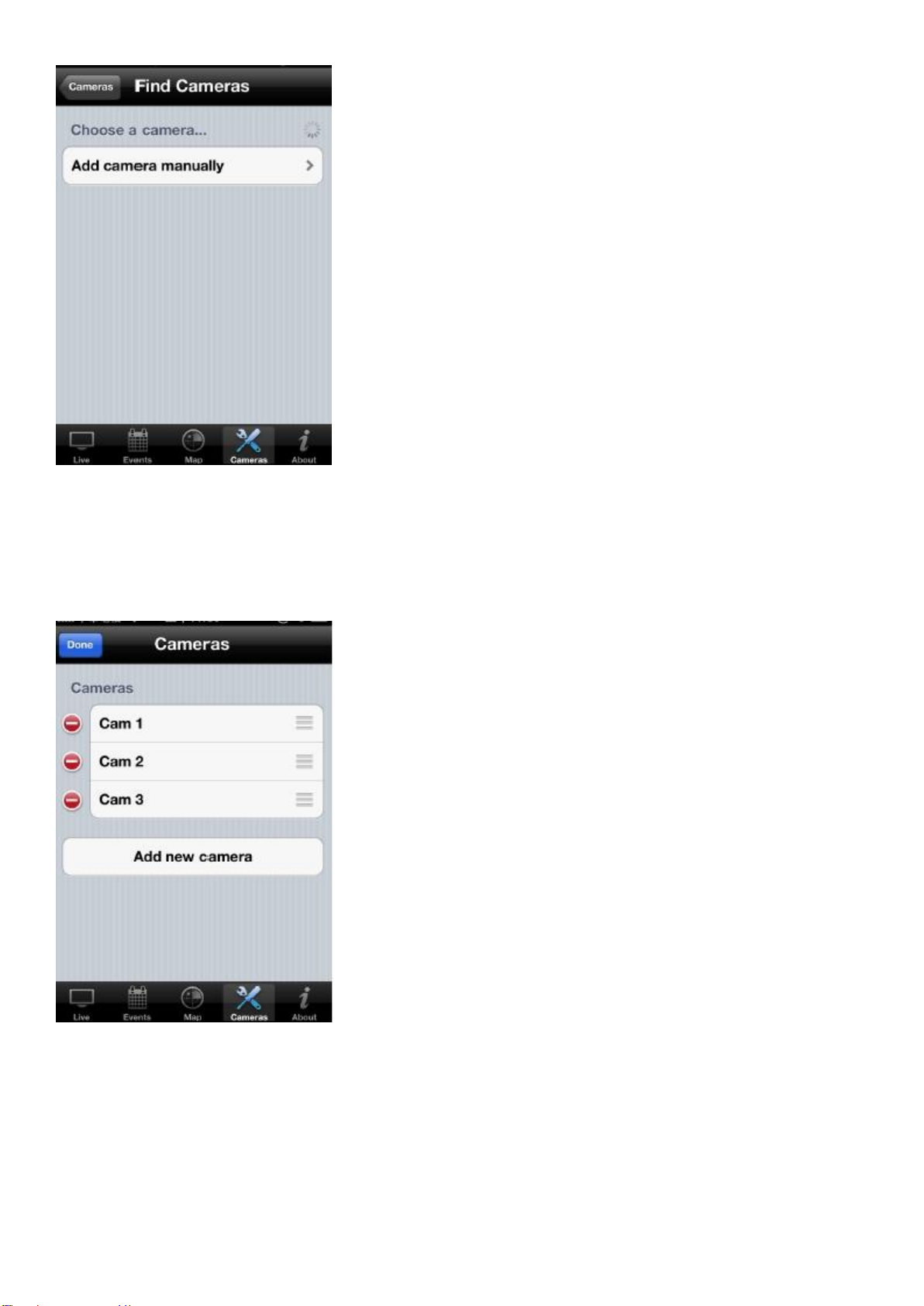
If cameras are found, they are shown in the camera list. If no camera is found,
an empty list is shown. Tap Add New Camera to manually add a network camera
Manually Adding a Network Camera on a LAN in IP Mode
Note: Cameras added in IP mode can only be accessed on the local network.
99
 Loading...