

Page 1
1
Page 2

ErP Announcement
Product: Internet Camera (IP Camera)
Purpose: 24 hour surveillance and transfer of footage for safety and health
reasons as intented use.
Detailed description:
- Health purposes: Users can pass through the Internet (from anywhere) to
control the product (IP Camera). It's intended to watch and listen to people
who need to be cared for at home and automatically sends e-mails and
phone alerts to warn observers and ask for their attention. The product
also provides a record function to retain all images and voice information
for the sake of reference.
- Safety purposes: Users can initiate a “motion detect” function to record
and send e-mails to notify them when doors or windows are opened –
potentially by unwarranted persons.
- General purposes: Record/monitor environment footage and sound and
store them onto a hard disk as a record.
As we cannot predict when events of this nature may occur, we need for the
product to remain active and alert at all times. If the product had to go into
“standby/off” mode, it would impact the effectiveness of recording and warning
functions resulting in users not getting the information they need.
Based on the ErP official journal of European Union
Directives 2009/125/CE of the European parliament and of the council of
21 October 2009 Article 15 sector 5 part (a) and (b) as below:
“Implementing measures shall have no significant negative impact on the
functionality of the product, from the perspective of the user.”
“Health, safety and environment shall not be adversely affected.”
We announce that the product need not comply with the (EC) No 1275
Standby and on/off mode function of Implementing Measurement.
We will keep up to the newest Implementing Measurements in the future
and make the necessary changes if it's related to this product.
2
Page 3

Notice according to GNU/GPL-Version 2
This product includes software that is subject to the GNU/GPL-Version 2.
You find the text of the license on the product cd/dvd. The program is free
software and distributed without any warranty of the author. We offer, valid
for at least three years, to give you, for a charge no more than the costs of
physically performing source distribution, a complete machine-readable
copy of the corresponding source code.
Please contact Edimax at: Edimax Technology co., Ltd, NO. 3, Wu-Chuan
3rd RD Wu-Ku-Industrial Park, Taipei Hsien, Taiwan. R.O.C., TEL :
+886-2-77396888, FAX : +886-2-77396887, sales@edimax.com.tw
Copyright by Edimax Technology Co, LTD. all rights reserved. No part of
this publication may be reproduced, transmitted, transcribed, stored in a
retrieval system, or translated into any language or computer language, in any
form or by any means, electronic, mechanical, magnetic, optical, chemical,
manual or otherwise, without the prior written permission of this company.
This company makes no representations or warranties, either expressed or
implied, with respect to the contents hereof and specifically disclaims any
warranties, merchantability or fitness for any particular purpose. Any software
described in this manual is sold or licensed "as is". Should the programs prove
defective following their purchase, the buyer (and not this company, its
distributor, or its dealer) assumes the entire cost of all necessary servicing,
repair, and any incidental or consequential damages resulting from any defect
in the software. Further, this company reserves the right to revise this
publication and to make changes from time to time in the contents hereof
without obligation to notify any person of such revision or changes.
The product you have purchased and the setup screen may appear slightly
different from those shown in this QIG. For more detailed information about this
product, please refer to the User Manual on the CD-ROM. The software and
specifications are subject to change without notice. Please visit our web site
www.edimax.com for the update. All rights reserved including all brand and
product names mentioned in this manual are trademarks and/or registered
trademarks of their respective holders.
3
Page 4

Table of Contents
Chapter I: Familiar with your Internet IP Camera ............................................. 6
1.1 Package Contents .............................................................................. 6
1.2 Basic Introduction ............................................................................... 7
1.3 Product Highlights ............................................................................... 8
1.4 Familiar with Key Components ........................................................... 9
1.5 Camera Installation ........................................................................... 11
1.6 Locate the IP Address of this IP Camera………………………………12
1.7 Log Onto Web Management Interface .............................................. 16
1.7.1 Install ActiveX……………………………………………………..19
Chapter II: Using Web Management Interface ............................................... 22
2.1 Camera Settings ............................................................................... 22
2.1.1 About ...................................................................................... 25
2.2 LAN Settings ..................................................................................... 26
2.2.1 IP Address .............................................................................. 26
2.2.2 RTSP…………………………………….…………………………28
2.2.3 PPPoE……………………………………………………………..29
2.2.4 Dynamic DNS ......................................................................... 30
2.2.5 UPnP ...................................................................................... 31
2.2.5 LoginFree ............................................................................... 33
2.3 WLAN Parameters ............................................................................ 34
2.4 Video ................................................................................................ 40
2.4.1 Dual Mode .............................................................................. 41
2.4.2 MPEG4 ................................ ................................................... 42
2.4.3 MJPEG ................................................................................... 43
2.5 Email & FTP...................................................................................... 44
2.5.1 Email Settings ......................................................................... 45
2.5.2 FTP Settings ........................................................................... 47
2.6 Motion Detection ............................................................................... 49
2.6.1 Basic Settings…………………………………………….……….49
2.6.2 Setup Motion Detection Regions………………………………..51
2.7 Schedule ........................................................................................... 53
2.8 System .............................................................................................. 55
2.8.1 Camera Information ................................................................ 56
2.8.2 Date / Time Setting ................................ ................................. 57
2.8.3 Utilities .................................................................................... 58
2.9 Status ............................................................................................... 60
4
Page 5

2.10 Account ........................................................................................... 61
2.11 Log………………………………………………………………………..63
2.12 Language Menu .............................................................................. 64
Chapter III: Using Surveillance Software ....................................................... 65
3-1 Installing IP Camera Surveillance Software ...................................... 65
3-2 Using IP camera surveillance software ............................................. 69
3-3 Configure IP camera surveillance software ...................................... 72
3-3-1 Configure cameras ................................................................. 72
3-3-2 General Settings .................................................................... 81
3-4 Change Display Layout .................................................................... 87
3-5 Full-screen mode .............................................................................. 90
3-6 Scan ................................................................................................. 91
3-7 Zoom-in / Zoom-out .......................................................................... 92
3-8 PTZ ................................................................................................... 93
3-9 Snapshot .......................................................................................... 94
3-10 Recording ....................................................................................... 95
3-11 Video Playback ............................................................................... 96
Chapter VI: How to View IP Camera over the Internet with iPhone…………...97
Chapter V: Appendix .................................................................................... 104
5.1 Troubleshooting .............................................................................. 104
5.2 Obtain a free Dyndns account ........................................................ 107
5.3 Use this IPCAM with a router or firewall………………………………113
5
Page 6

Chapter I: Familiar with your Internet IP Camera
Item Name
Quantity
1
IP Camera
1 2 Power Adapter
1 3 Ethernet Cable
1 4 Quick Installation Guide
1
5
CD-ROM (Including Manual/Utility/Multi-Language
QIG)
1
6
Mounting Kit
1
1.1 Package Contents
Thank you for purchasing this IP camera! Before you start to use this IP
camera, please check the package contents. If anything is missing, please
contact the dealer of purchase and return the package to claim for missing
contents.
6
Page 7

1.2 Basic Introduction
Congratulations on buying this Edimax IP Camera! You've chosen well. This IP
camera is ideal for all kinds of video surveillance from home and office safety
to child and pet monitoring purposes. This Edimax IP camera is tailor made to
stream live video over your network, so you can view its footage from
anywhere on your local computers. Better yet, you can view its video via the
Internet! The Edimax IC-3005 series features extremely high picture quality
matched by a high frame rate video streaming because of advanced video
compression. To get the best video quality, select MPEG4 or MJPEG,
depending on your network settings.
Before enjoying your new IP camera, please check the package contents. If
anything is missing, return this package to your dealer to claim the missing
contents.
7
Page 8

1.3 Product Highlights
No pre-loaded software required - all you need is a browser like Internet
Explorer 6 (and above, with plugin installed).
Supports VGA (640 x 480), QVGA (320 x 240), and QQVGA (160 x 120)
video resolution, with auto-exposure control
Supports two video compression formats (MJPEG and MPEG4).
Supports all major web browser, including Microsoft Internet Explorer,
Apple Safari and Firefox.
Wired and wireless network (802.11b / 802.11g / 802.11n) support.
(IC-3005Wn only)
Wireless data encryption (WEP / WPA). (IC-3005Wn only)
WPS (Wi-Fi Protected Setup), the easiest way to setup a secure wireless
connection. (IC-3005Wn only)
Supports DHCP and you can also assign a fixed IP address to the camera
also.
Supports Dynamic DNS (used to allocate the IP camera‟s Internet address,
when the ISP you‟re using does not assign you with a fixed Internet
address).
Supports UPnP, Windows XP (and above) will discover this IP camera in
network neighbor automatically.
Send captured picture by Email or FTP when motion is detected. Also
support FTP / Email scheduling.
Configurable motion detection sensitivity (6 levels from most sensitive to
least sensitive).
Built-in real-time clock, date and time information will be recorded with
every captured picture / video clip (also supports auto time
synchronization via network time protocol).
Upgradeable firmware - enjoy new functions without buying a new
camera!
Supports up to 16 users, and you can set different password to different
user.
Usage and event logging.
*Some functionality like „fit to window‟ only works on Microsoft Internet Explorer.
8
Page 9
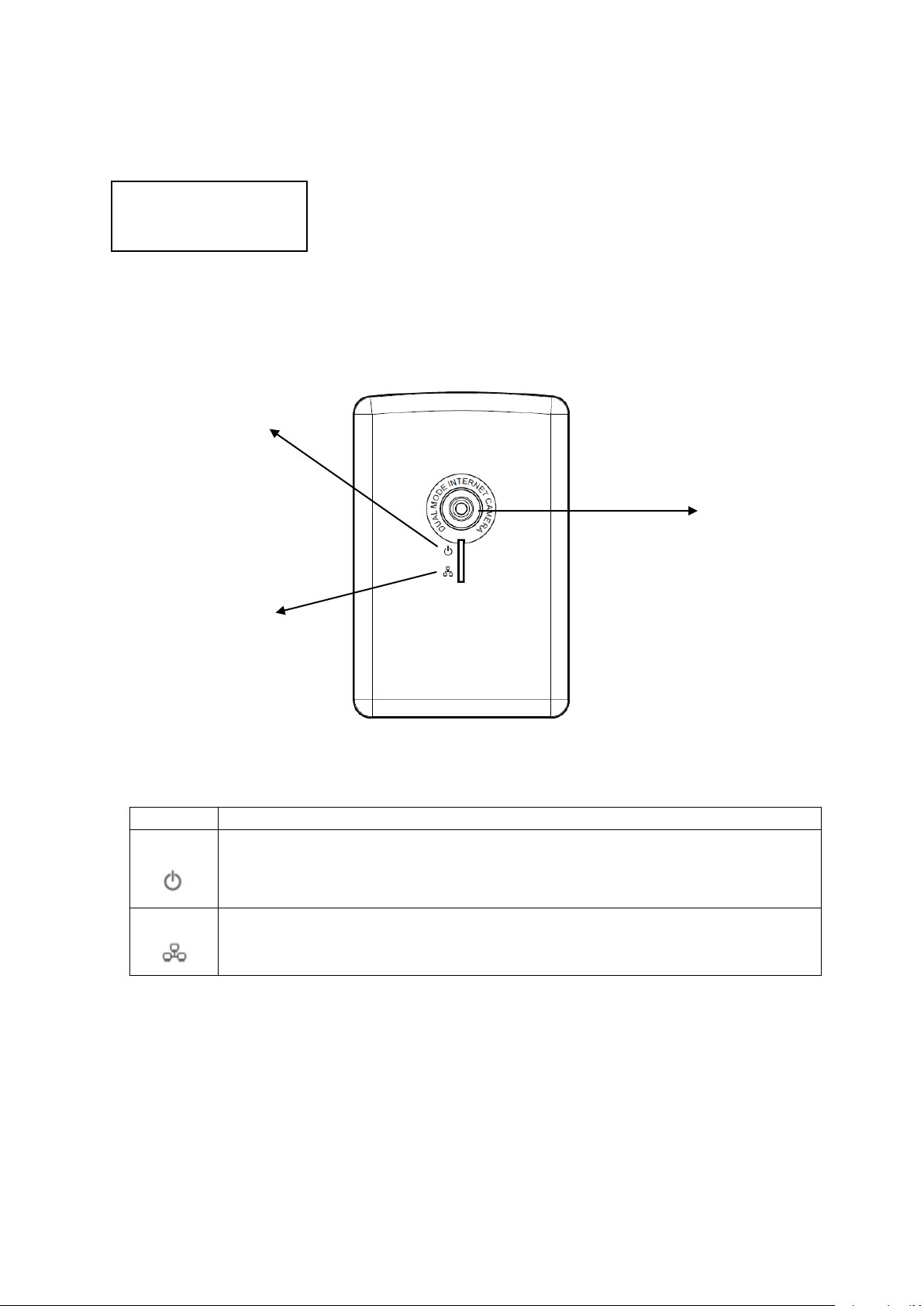
1.4 Familiar with Key Components
LED
Description
Status
Steady on: System is correctly powered on
Slow Blinking: Camera is booting
Quick Blinking: Camera is waiting for WPS connection
Network
Steady; Network is connected
Blinking: Data is transmitted
Front View
LED Blue:
Status
LED Green:
Network
Camera Focus
There are two LEDs indicating the camera's status and networking status.
9
Page 10
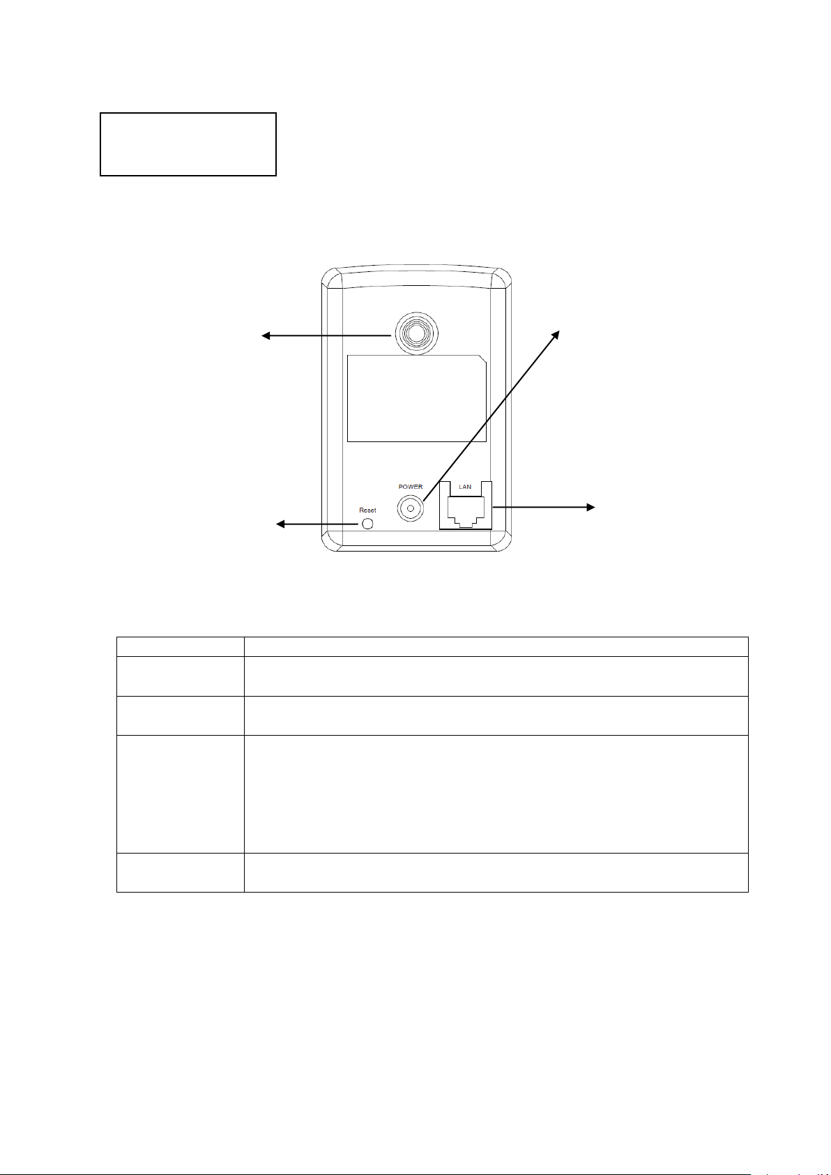
Name
Description
Tripod
Connector
Connects to standard tripod / camera wall holder
Power
Connector
Connects to 5V DC power adapter
Reset to
Default / *WPS
(IC-3005Wn
only)
Press and hold this button for more than 5 seconds to reset the
camera settings to factory default.
Press the WPS button (click) on the IP Cam and click on the
Access Point that you want to wirelessly connect it to.
Ethernet
Connector
Connects to your local area network with Ethernet cable
Back View
Tripod Connector
Reset to Default
Power Jack
LAN Port
10
Page 11

1.5 Camera Installation
1. Unpack your Edimax IP Camera from its packaging and ensure that all the
items listed in Chapter 1 are there.
2. Connect the Edimax IP Camera to your network by attaching a network
cable from your switch or router to the LAN port on the IP Camera.
3. Connect the power adapter to the IP Camera and plug the adapter into a
power outlet. When the IP Camera is ready, the Blue LED will light up.
Note: It is highly recommended to use only the power adapter shipped with the
IP Camera. Do NOT use any other power adapter and avoid possible damage
to your new device.
11
Page 12
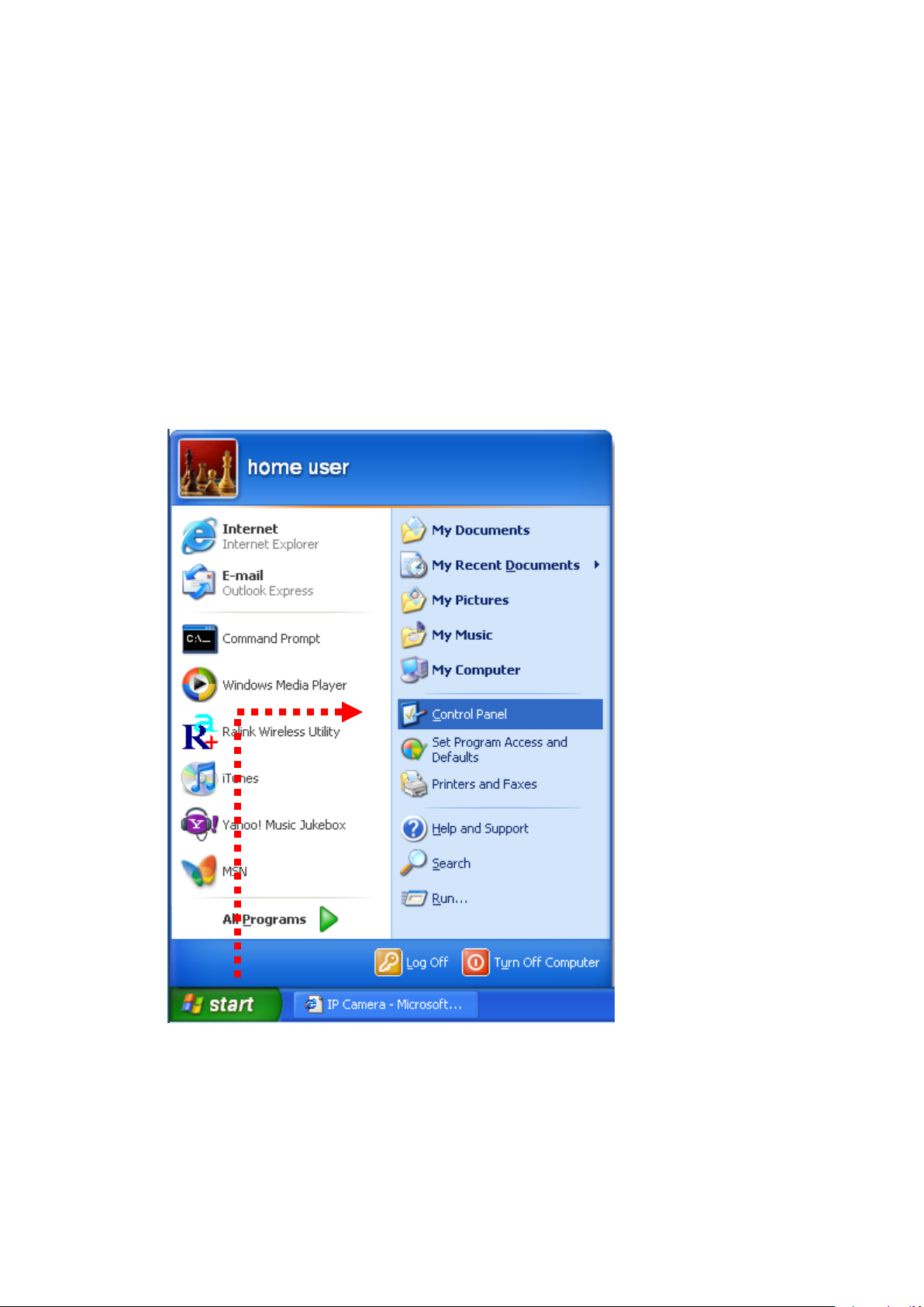
1.6 Locate the IP Address of this IP Camera
Default IP address of this IP camera is 192.168.2.3. If you wish to assign
another IP address to this IP camera, you have to log onto the web
configuration interface of the camera first.
If the left three fields of the IP address of your computer is not 192.168.2, you‟ll
have to change the IP address of your computer first:
1. Click „Start‟ -> „Control Panel‟
12
Page 13
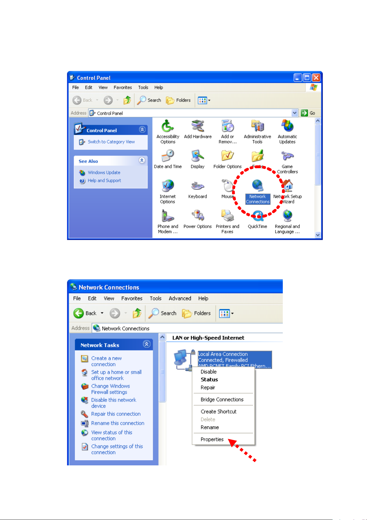
2. Double-click „Network Connections‟ icon.
3. Right-click „Local Area Connection‟, and click „Properties‟.
13
Page 14
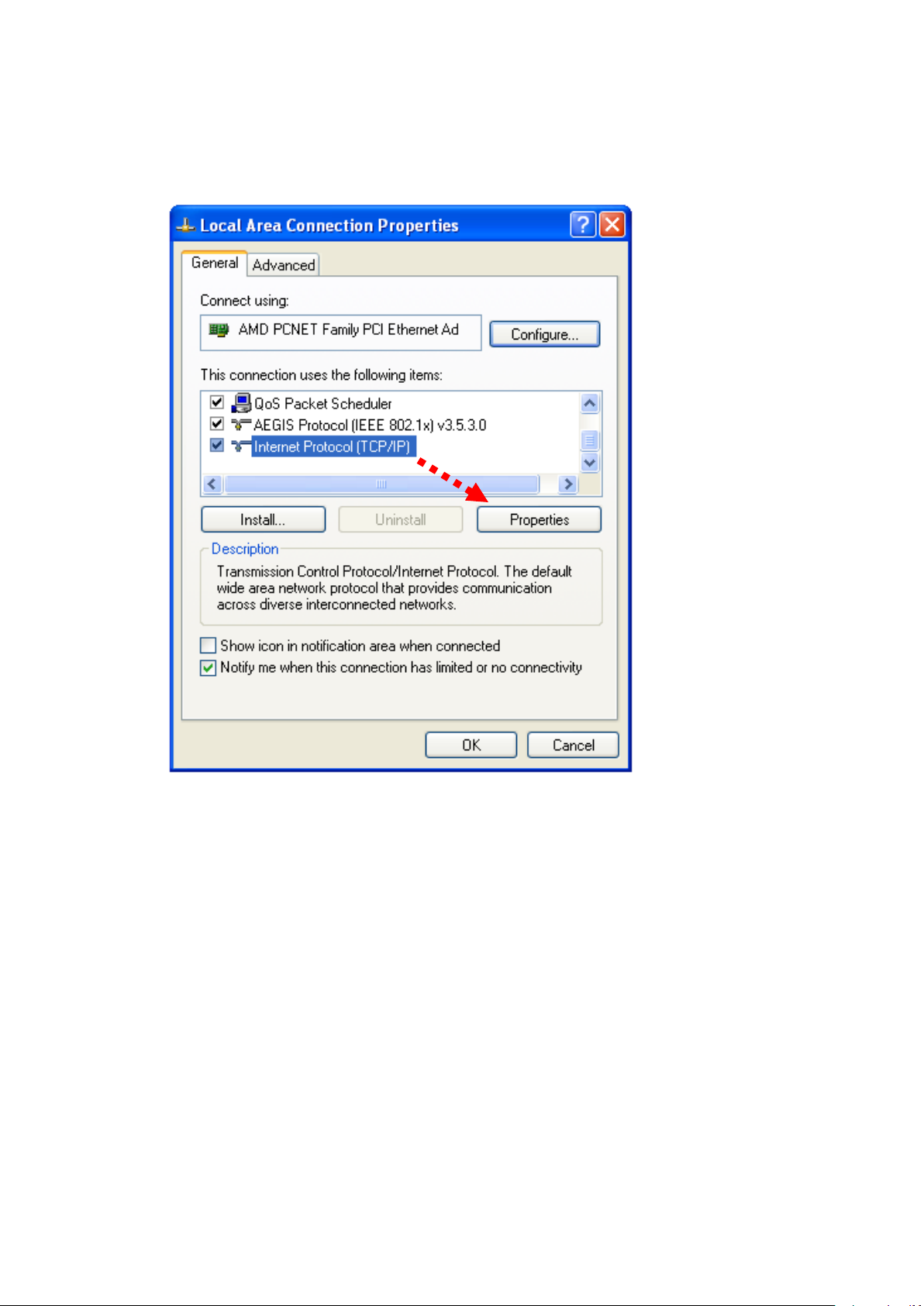
4. Select „Internet Protocol (TCP/IP)‟, then click „Properties‟.
14
Page 15
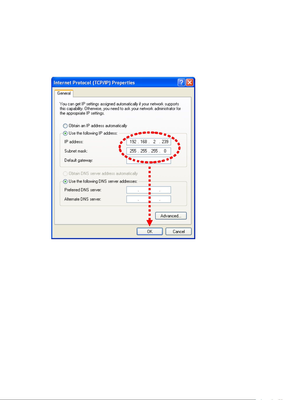
5. In „IP address‟ field, please fill in any IP address begins with „192.168.2‟,
and ends with a value greater than 2 and less than 254 (You can use the
example in the picture „192.168.2.239‟). In Subnet mask field, please fill
„255.255.255.0‟. Please keep all other fields empty, and click „OK‟.
If you changed the IP address of this IP camera and you forget it, there‟re 2
ways you can recover it:
a. Press and hold the „Reset‟ button located at the bottom of this IP
camera, to clear all settings of the IP camera and reset the IP address
back to 192.168.2.3. You‟ll lose all settings in the IP camera.
b. Ask network administrator to check the DHCP release table, if the
camera was set to obtain the IP address by DHCP, a new record will
be added to DHCP release table on DHCP server when the IP camera
is connected to the local area network.
15
Page 16
1.7 Log Onto Web Management Interface
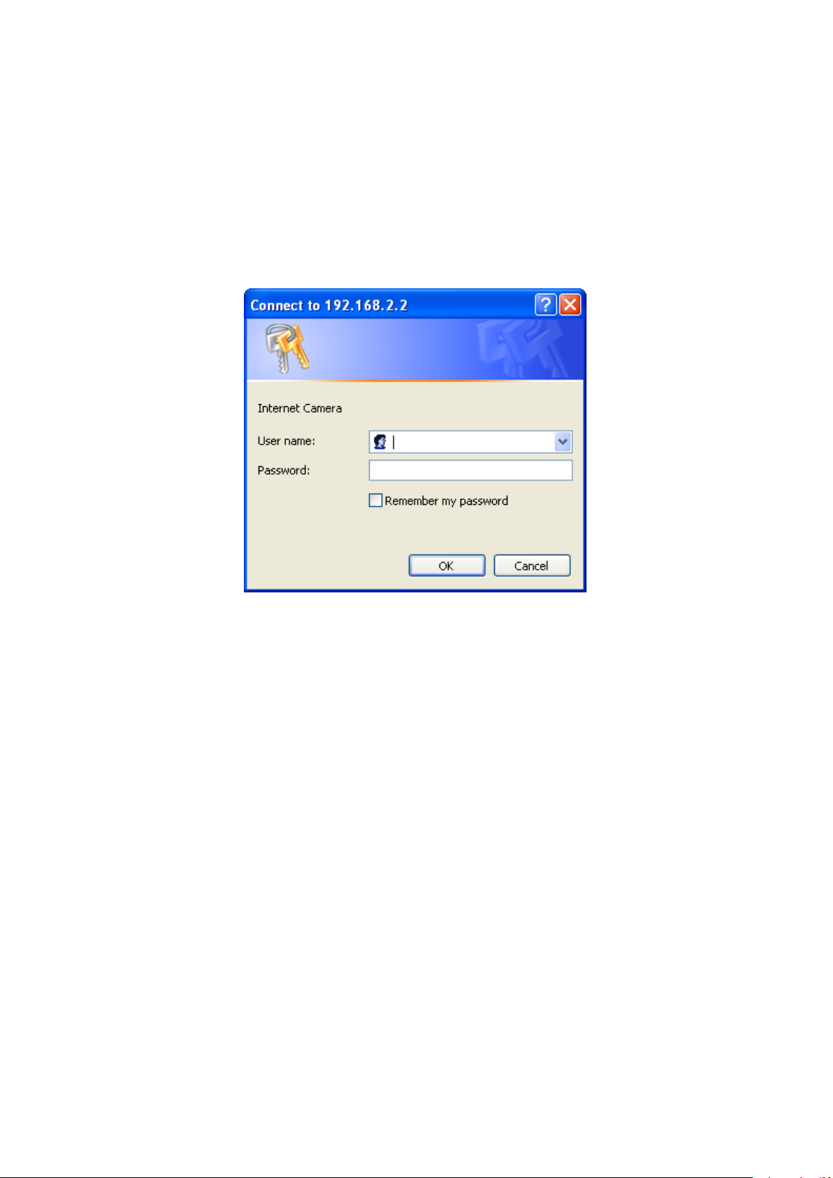
Make sure the IP camera is correctly powered (Power LED is on), and then
launch Internet Explorer and type the IP address of the IP camera in address
bar of Internet Explorer. You should be prompted to input the user name and
password:
Default user name is „admin‟ (in lower case) and password is „1234‟. Click „OK‟
to continue after user name and password has entered.
If you‟re rejected, maybe the password has been modified previously. This
should not happen if this is a newly-purchased camera, however, if you get the
camera from someone else, the password would be changed. Please try to
obtain the correct user name / password, or you‟ll have to reset the camera.
16
Page 17
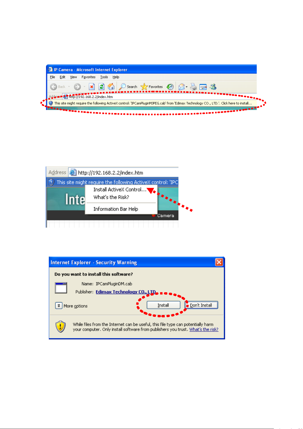
After logged on, you should see the following messages at the top of Internet
Explorer:
If not, please go to section 1.8.1 „Install ActiveX‟.
This IP camera requires a special ActiveX control (A.K.A. „Plugin‟) to work.
Please click on the message, and select „Install ActiveX Control…‟:
When you‟re prompted, click „Install‟ to continue.
17
Page 18
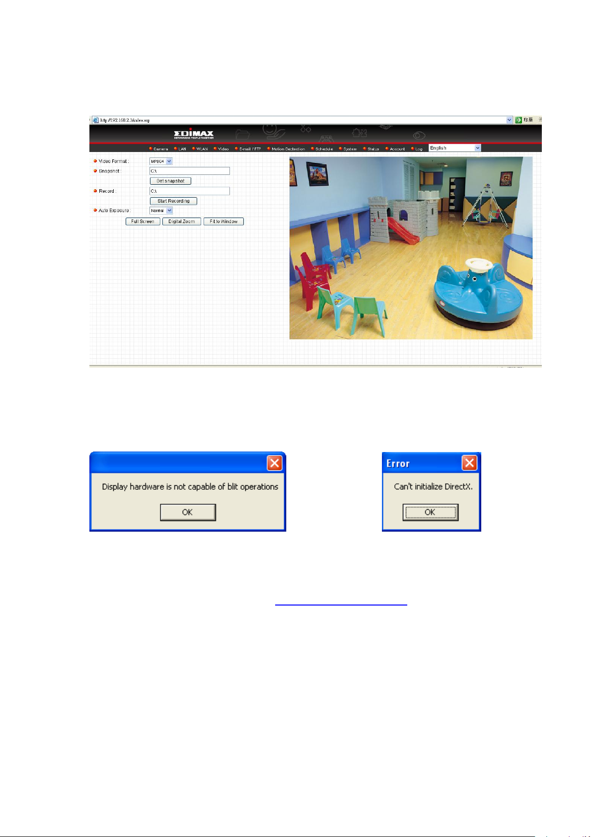
You should be able to see the image from camera now:
OR
Note: If you see one of these messages (or both):
Your computer may not have the display capability that this IP camera requires,
or you don’t have Microsoft DirectX® installed. Please download Microsoft
DirectX® from Microsoft’s website (http://www.microsoft.com), and try again.
In some cases, your computer is able to display the image from IP camera
correctly, but you’ll still see these messages. If this happens, just ignore them.
18
Page 19
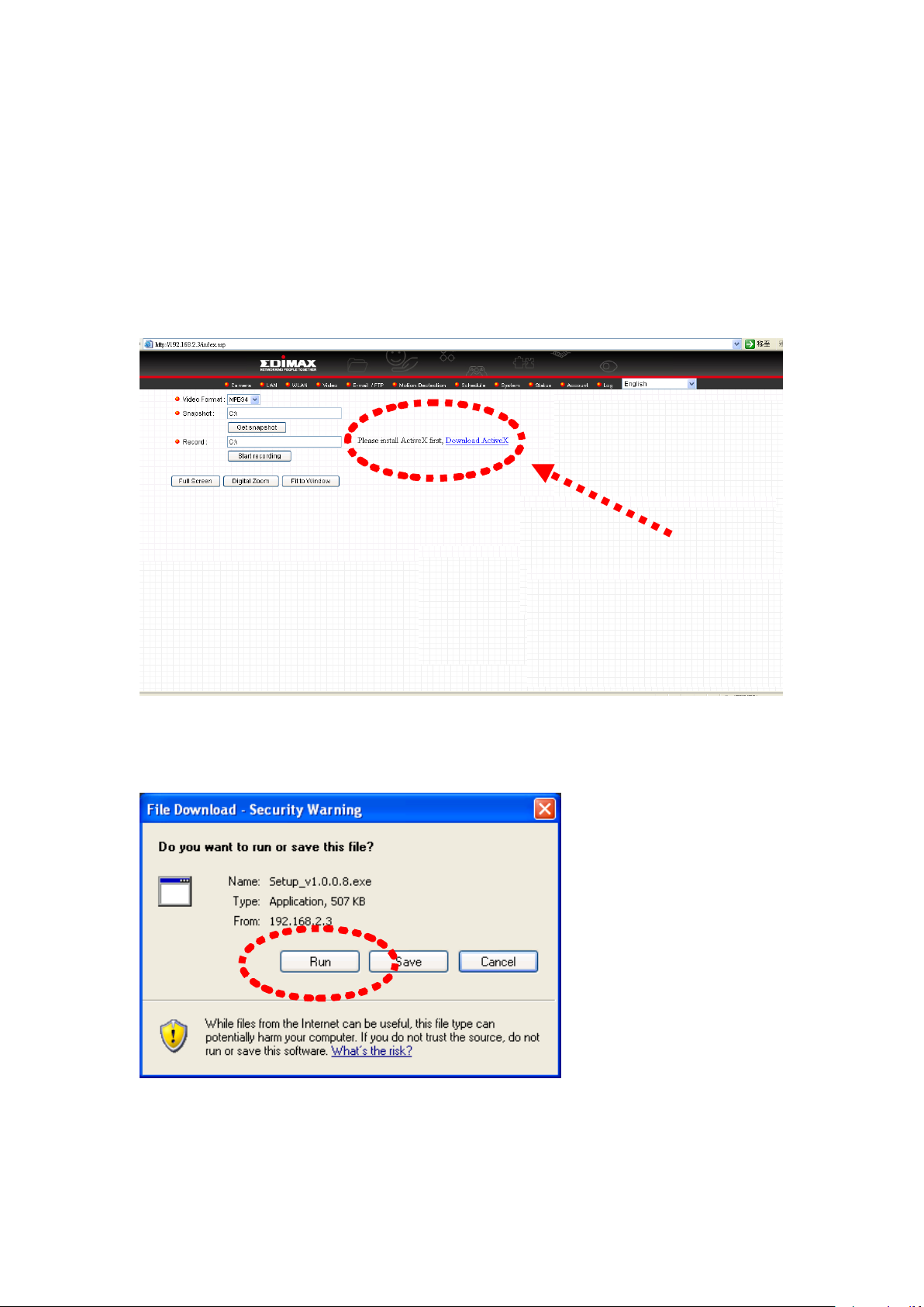
1.7.1 Install ActiveX
Most of browsers support Microsoft ActiveX, but if ActiveX is not present on
your computer, you need to install it before you can use this Internet camera.
If you see this message when you log onto IP camera, please click the link to
download ActiveX:
Press „Run‟ to download ActiveX installation package:
Press „Run‟ to install ActiveX:
19
Page 20
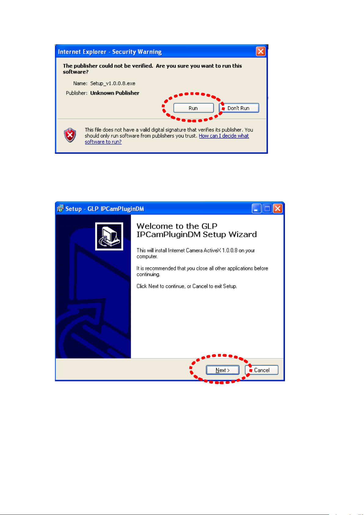
Press „Next‟ to start installation; press „Next‟ button when you‟re prompted,
until installation is complete:
20
Page 21
Press „Finish‟ when you see this message. Now please go back to last section
to install IP camera plugin.
21
Page 22
Chapter II: Using Web Management Interface
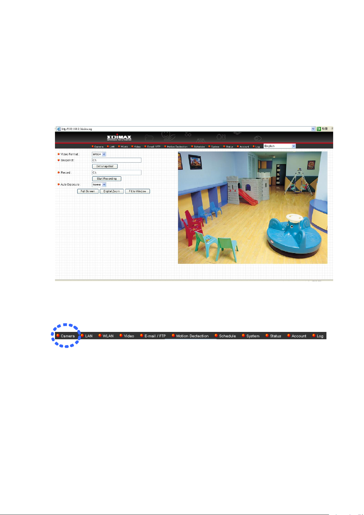
2.1 Camera Settings
The first menu after you logged onto web management interface is „Camera‟,
and this is the only menu you can see the real-time image from camera.
You can always back to this menu by clicking „Camera‟ on the top of web
management interface.
22
Page 23
The descriptions of every setting in this menu will be given below:
Item
Description
Video Format
Specifies video encoding format. You can choose
MPEG4 or MJPEG (Motion-JPEG).
MPEG4 mode also supports motion detection
Snapshot
Take a snapshot picture and save the picture to your
computer‟s hard drive. Click on directory display and
you‟ll be prompted to select a folder to save snapshot file.
Record
Start video recording and save recorded video clip to
your computer‟s hard drive. Click on directory display and
you‟ll be prompted to select a folder to save snapshot file.
Auto Exposure
Enable or disable automatic exposure control. There are
3 levels of automatic exposure control: Dark, Normal, and
Bright. Select one of them to control the brightness of
image. Select „Disable‟ to disable automatic exposure
control.
Full Screen
Click this button and the image captured by camera will
be displayed in full-screen mode. To resume, double-click
the image.
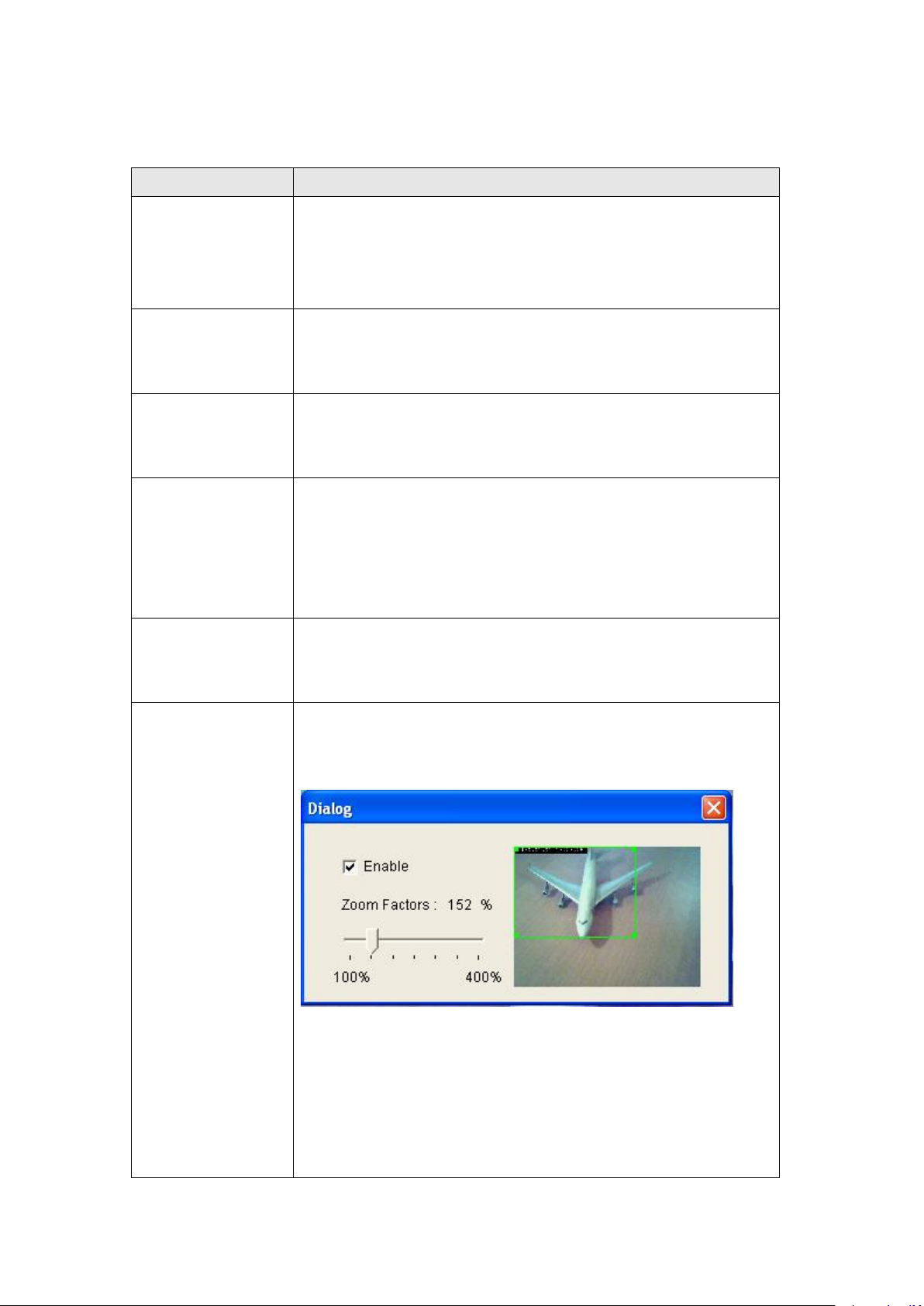
Digital Zoom
Click this button to enable digital zoom (video
magnification) function:
Check „Enable‟ box to enable digital zoom, and you can
set the percentage of zoom from 100% (no magnification)
to 400%. You can also drag the green square by mouse
and put it on the area you wish captured image to be
magnified.
23
Page 24

To exit digital zoom setting, press button.
Fit to Window
Click this button and captured image will fit to window
size.
*Note: If you‟re not using Microsoft Internet Explorer as web browser, some
functionalities may not work properly.
24
Page 25
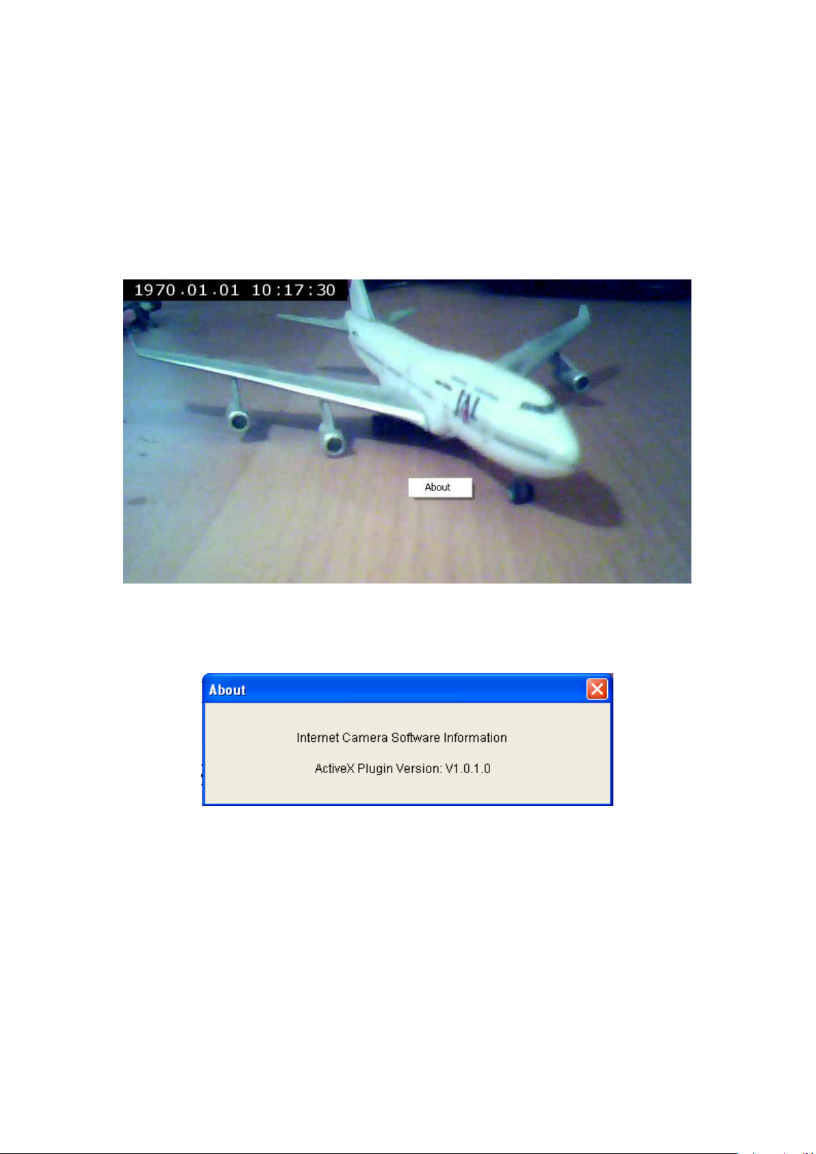
2.1.1 About
This function will provide you with the version number of current IP
camera plugin, which is useful when you need online support.
To see version information, right-click on the image. A pop-up menu will appear:
Select „About‟ and the version information will appear:
25
Page 26

2.2 LAN Settings
All network-related settings can be found in this menu, and you have to specify
TCP/IP parameters in this menu if you want to change IP address, use PPPoE,
Dynamic DNS, and activate UPnP function.
You can access this menu by clicking „LAN‟ on the top of web management
interface.
2.2.1 IP Address
You can define IP address and select the port number you wish to use here.
26
Page 27

The descriptions of every setting in this menu will be given below:
Item
Description
Network Type
This camera can obtain the IP address from DHCP
server automatically (if you have one), or set a fixed IP
address. Select „DHCP‟ to obtain IP address
automatically or „Static IP Address‟ to assign this IP
camera with a fixed IP address.
When „DHCP‟ is selected, IP address parameters below
will be grayed out.
IP Address
Specify the IP address for this IP camera here.
Subnet Mask
Specify the subnet mask for this IP camera here.
Gateway
Specify the gateway address of the local network here.
Primary DNS
Specify the IP address of DNS server here. Please input
IP address only. If you don‟t know the address of DNS
server, ask network administrator or your ISP for help.
Secondary DNS
Specify the IP address of backup DNS server here. When
primary DNS is unreachable, IP camera will use the IP
address specified here as DNS server.
This field is optional.
AV Control Port
Specify the port number of video transfer here. If you
have firewall on your network, you need to allow
computers on Internet to access this port number of the
IP address of IP camera, or you‟ll not be able to view
video from Internet.
Web Port
Specify the port number of web management interface
here. If it‟s not 80, you‟ll have to add „:port’ after the IP
address / hostname of this IP camera.
For example, if the HTTP port number you specified here
is 90 and the IP address of IP camera is 10.20.20.30,
then you have to input ‘http://10.20.20.30:90’
in the address bar of Internet explorer.
Click „Apply‟ to save settings and make the new settings take effect.
27
Page 28
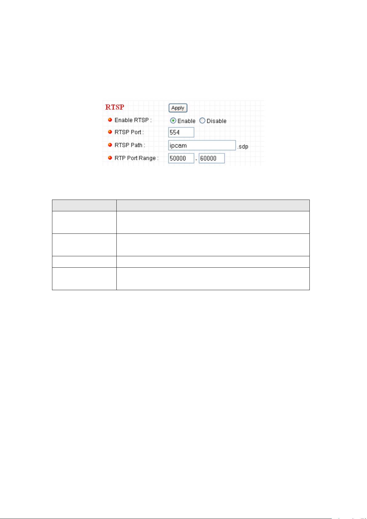
2.2.2 RTSP
Item
Description
Enable RTSP
Select „Enable‟ to activate RTSP function of this IP
camera, select „Disable‟ to disable it.
RTSP Port
Input the port number which RTSP will use. Default
setting is 554.
RTSP Path
Input the path of RTSP stream. **
RTP Port Range
Input the port range of RTP. Default setting is 50000 to
60000.
RTSP (Real-Time Streaming Protocol) allows you to view live video captured
by IP camera. You can set RTSP related settings here.
The descriptions of every setting in this menu will be given below:
Click „Apply‟ to save settings and make the new settings take effect.
28
Page 29

2.2.3 PPPoE
Enable PPPoE
Select „Enable‟ to activate PPPoE function of this IP
camera, select „Disable‟ to disable it.
User Name
Input the PPPoE username assigned by your ISP here.
Password
Input the PPPoE password assigned by your ISP here.
MTU
Input the MTU (Maximum Transmission Unit) given by
your ISP here. Ask your ISP if you don‟t know what value
you should input here. Default value should work with
most of ISPs and will give you a nice network
performance.
Click „Apply‟ to save settings and make the new settings take effect.
29
Page 30
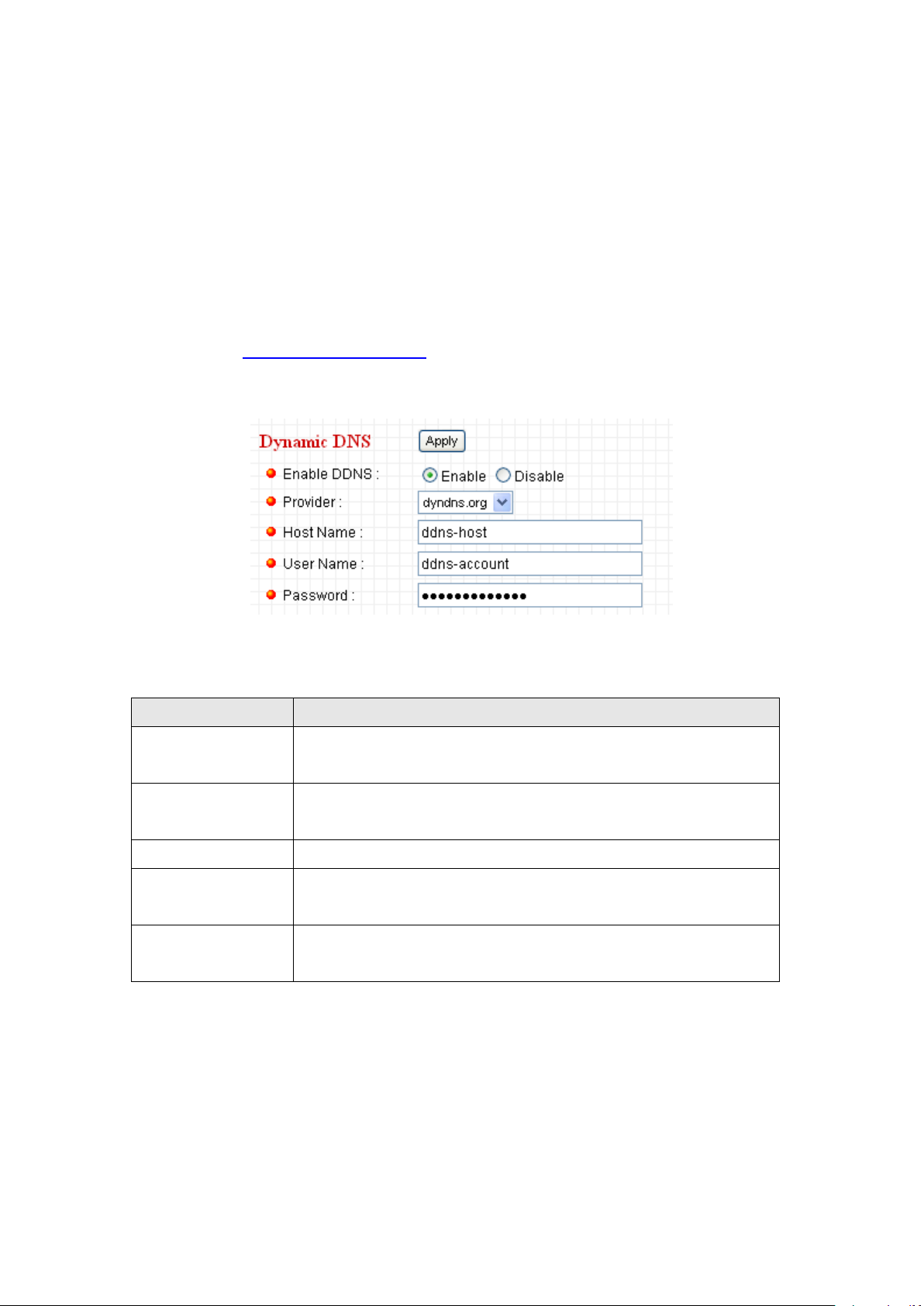
2.2.4 Dynamic DNS
Item
Description
Enable DDNS
Select „Enable‟ to activate Dynamic DNS function of this
IP camera, select „Disable‟ to disable it.
Provider
Select dynamic DNS service provider here. Only
dyndns.org is available currently.
Host Name
Input dynamic DNS host name here.
User Name
Input dynamic DNS user name here, must be the same
as the one you applied on dyndns.org.
Password
Input dynamic DNS password here, must be the same as
the one you applied on dyndns.org.
If your ISP does not give you a fixed Internet IP address (i.e. the Internet
address you‟re using when you access the Internet is not always the same –
ask your ISP for detailed information), you can use this function to help you
locate the IP address of this IP camera when you‟re away from home or office.
Before you can use this function, you‟ll need to apply for an account at
dyndns.org (http://www.dyndns.org). Detailed instructions of how to apply a
new account can be found on dyndns.org‟s website.
The descriptions of every setting in this menu will be given below:
Click „Apply‟ to save settings and make the new settings take effect.
30
Page 31
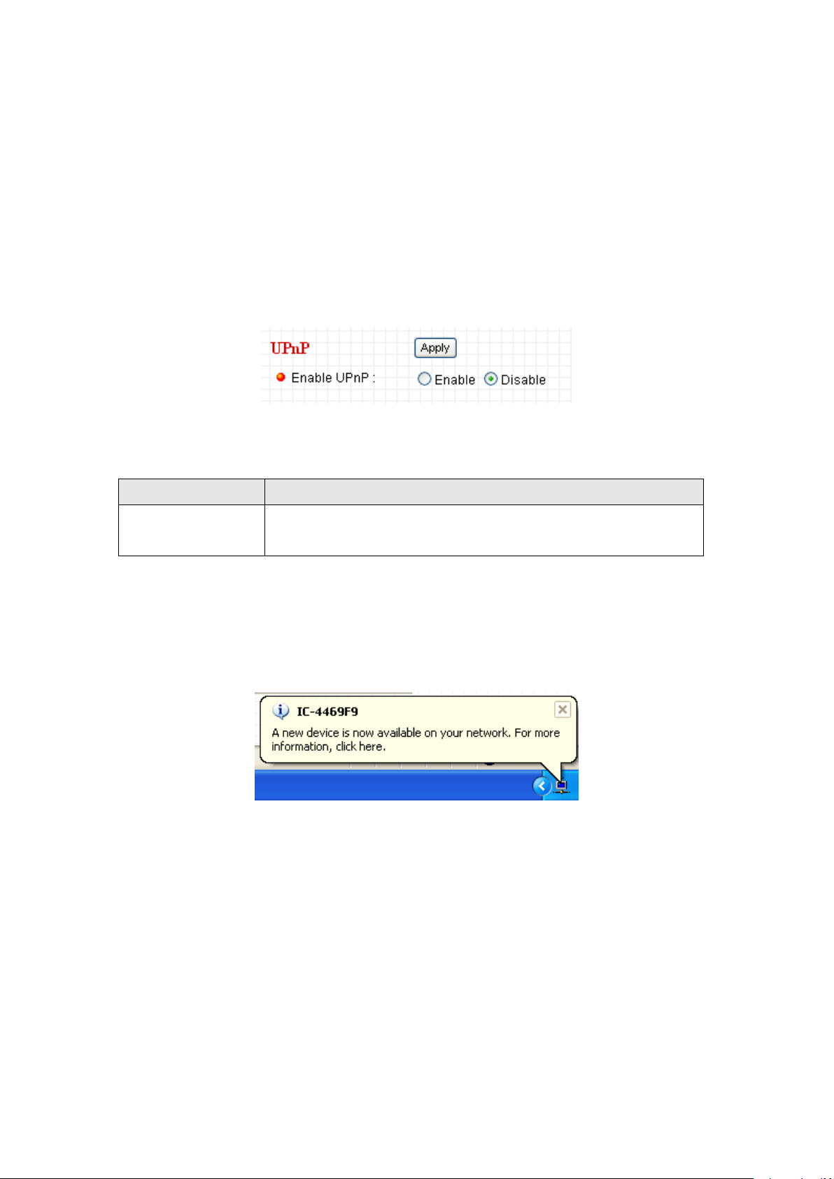
2.2.5 UPnP
Item
Description
Enable UPnP
Select „Enable‟ to activate UPnP function of this IP
camera, select „Disable‟ to disable it.
When UPnP function is activated, all UPnP-compatible computers / network
devices will be able to discover this IP camera automatically (only those in the
same local network).
This function is useful and you don‟t have to remember the IP address of this
IP camera. Simply open „Network neighbor‟ and it‟s there!
The descriptions of every setting in this menu will be given below:
Click „Apply‟ to save settings and make the new settings take effect.
After UPnP function is activated, a popup message will appear:
31
Page 32

Click the message to open „My Network Places‟, and you‟ll see the IP camera:
You can double-click the icon to launch Internet Explorer and log onto IP
camera‟s web management interface directly.
32
Page 33

2.2.6 LoginFree
Item
Description
LoginFree
Specify the file name of the picture here. If you want to
disable this function, leave it blank.
You can specify a filename here, and everyone who knows this filename
can gain access to the picture captured by the IP camera with this name
with .jpg file extension.
For example, if the filename you specified here is „loginfree‟ and your IP
camera‟s IP address is „192.168.2.3‟, then everyone on the network can
access to the picture taken by the IP camera at
„http://192.168.2.3/loginfree.jpg‟.
This function is for convenience only, and anyone who knows this
filename will be able to see the picture taken by your IP camera. Please
think again before you use this function.
The descriptions of every setting in this menu will be given below:
Click „Apply‟ to save settings and make the new settings take effect.
33
Page 34

2.3 WLAN Parameters
If you wish to use wireless network instead of wired network connection, you
have to set wireless LAN parameters here.
You can access this menu by clicking „LAN‟ on the top of web management
interface.
34
Page 35

The descriptions of every setting in this menu will be given below:
Item
Description
Self PinCode
A random 8-digit code will be displayed here. If the
wireless AP you wish to connect supports PINCODE,
please input this code to the AP you wish to connect. This
code changes every time you enter this page.
Configure via
Push Button
If the wireless AP you wish to connect supports push
button WPS configuration, click „Start PBC‟ and press the
WPS button on the wireless AP to start pairing.
You can also press „WPS / Reset‟ button located at the
back of IP camera for the same purpose. DO NOT press
and hold „WPS / Reset‟ button for too long time, if you
press and hold „WPS / Reset‟ button for more than 10
seconds, all settings in IP camera will be lost!
Configure via
PinCode
If the wireless AP already generates a 8-digit code,
please input the code here and click „Start PIN‟ button to
start pairing.
Wireless
Connection
Select „Enable‟ to activate wireless network function of
this IP camera, select „Disable‟ to disable it.
Network Type
Select the network type of wireless connection.
Available options are „Infrastructure‟ (Connect the IP
camera to a wireless access point), and „Adhoc‟ (This IP
camera will become a stand-alone wireless network
point, other wireless computers / devices can discover
this IP camera and connect to it without wireless access
point).
You can set to „Adhoc‟ when you don‟t have any wireless
access point, but your computer has wireless network
card. Set to „Infrastructure‟ when you have wireless
access point, and you have computers with wired
network connection.
Available
Networks
Here shows all wireless access points found by this IP
camera. Please note not all access points will be
displayed at the same time, if the access point you wish
35
Page 36

to connect does not appear, you may have to click
„Refresh‟ button for several times until it appears.
The descriptions of all fields is listed below:
Connect: You can select the wireless access point you
wish to connect here.**
SSID: the SSID of all found wireless access points will be
shown here. Some wireless access point may hide their
SSID, in this case, you have to identify them by their
MAC address.
MAC Address: If you there are many wireless access
points in proximity or some wireless access point hides
it‟s SSID, you can use MAC address to distinguish them.
Signal: Shows the radio signal strength in percent.
Channel: Shows the radio channel of this wireless access
point.
Encryption: Shows the encryption type used by this
wireless access point. You must use the same encryption
type if you wish to connect to a certain wireless access
point. If the wireless access point does not use
encryption, „Disabled‟ will be displayed here.
Network Type: Shows the network type of a certain
wireless access point (Infrastructure or Adhoc).
SSID
Input the SSID of the wireless access point you wish to
connect. It should be less than 32 alphanumerical
characters.
When you select a wireless access point above, it‟s SSID
will be filled in this field automatically. However, if the
SSID is not displayed (the wireless access point you
36
Page 37

selected choose to hide it‟s SSID), you have to know it‟s
SSID and input it here, or you will not be able to connect
it.
Channel
Select the radio channel you wish to use here. When
network type is „Infrastructure‟, the radio channel is
auto-selected according to the channel that wireless
access point uses. You can only select the channel
number when network type is „Adhoc‟.
Basic Rate
Select the maximum wireless data transfer rate here,
from 1Mbps to 54Mbps. Maximum transfer rate for
802.11b wireless network is 11Mbps, and maximum
transfer rate for 802.11g wireless network is 54Mbps.
It‟s recommended to select „Auto‟, so the data transfer
rate will vary according to the actual signal strength and
quality.
Authentication
Select the wireless authentication here, and this setting
must be the same with the wireless access point you
selected.
When you select a wireless access point from the list, it‟s
authentication type will be selected automatically, and
you should not modify it or you will not be able to connect
to the wireless access point you selected.
Available options are: None (no authentication), Open
System, Shared Key System, WPA-PSK, WPA2-PSK,
and WPANone (the last one is only for Adhoc).
Encryption Type
Select the wireless encryption type here, and this setting
must be the same with the wireless access point you
selected.
When you select a wireless access point from the list, it‟s
encryption type will be selected automatically, and you
should not modify it or you will not be able to connect to
the wireless access point you selected.
Available options are: None, WEP, TKIP and AES. The
37
Page 38

options available here will vary depends on the
authentication type you selected above. If an
authentication type does not support need encryption,
this field will be grayed out.
WPA Pre-Shared
Key
Input the WPA pre-shared key here.
This field is only available when authentication type is
WPA-PSK or WPA2-PSK, and will be grayed out when
other authentication type is selected.
WEP Key Length
Please select the key length when you use WEP
encryption. Available options are 64-bit and 128-bit.
Selecting „128-Bit‟ is safer, however, it would make the
network a little bit slower.
If the key length is 64-bit, you should input 10 HEX
characters or 5 ASCII characters, like 112233aabb (HEX)
or MYWEP (ASCII).
If the key length is 128-bit, you should input 26 HEX
characters or 13 ASCII characters, like
11223344556677889900abcdef (HEX) or
myweppassword (ASCII).
WEP Key Format
Select the Key Format of WEP key here. Available
options are „HEX‟ and „ASCII‟.
When you select „HEX‟ WEP key format, you can only
use numbers (0 to 9), and alphabet a to f as WEP key;
when you select „ASCII‟ WEP key format, you can use all
alphanumerical characters, and is case sensitive.
Default Key
Select the default key set that is IP camera should use
against the wireless access point when WEP encryption
is used.
Available options are 1 to 4.
WEP Key 1
Input the 1st set of WEP key here. At least a set of WEP
key is required and you should use 1st WEP key if you
38
Page 39

only have one WEP key.
WEP Key 2
Input the 2nd set of WEP key here.
WEP Key 3
Input the 3rd set of WEP key here.
WEP Key 4
Input the 4th set of WEP key here.
Click „Apply‟ to save settings and make the new settings take effect.
39
Page 40

2.4 Video
You can specify the video and audio parameters of this IP camera here.
40
Page 41

2.4.1 Dual Mode
Item
Description
Default Video
Format
Specify default video encoding format of this IP camera
here. Available options are MPEG4 and MJPEG.
This IP camera supports two video encoding formats: MPEG4 and
MJPEG. You can select the encoding format from one of them.
The descriptions of every setting in this menu will be given below:
Click „Apply‟ to save settings and make the new settings take effect.
41
Page 42

2.4.2 MPEG4
Item
Description
Video Resolution
Specify video resolution of MPEG4 video encoder.
Available options are VGA and QVGA resolution. VGA
resolution provides more details than QVGA, but requires
more network bandwidth.
Video Quality
Specify video quality. There are two video quality types:
CBR (Constant Bit Rate), and VBR (Variable Bit Rate):
CBR: The video bit rate is fixed, you can select a bit rate
from dropdown menu. Higher bit rate means better video
quality. But if your network bandwidth is limited, select a
lower bit rate will help.
VBR: Video bit rate is variable based on the video
content being transferred. There‟re 5 levels of setting
from „Lowest‟ to „Highest‟. Select „Lowest‟ will lower video
quality and save network bandwidth; if a better video
quality is required, select „High‟ or „Highest‟.
Video Frame
Rate
Specify video refresh rate of MPEG4 video encoder.
Higher video refresh rate provides more details about
motion, but requires more network bandwidth.
CAUTION: Choosing a low frame rate will save
bandwidth, but may not be able to capture every motion if
the object that IP camera points to is moving too fast.
If you selected „MPEG4‟ as the video encoding format of this IP camera,
you can specify the parameters of MPEG4 video encoder here.
The descriptions of every setting in this menu will be given below:
Click „Apply‟ to save settings and make the new settings take effect.
42
Page 43

2.4.3 MJPEG
Item
Description
Video Resolution
Specify video resolution of MJPEG video encoder.
Available options are VGA (640x480), QVGA (320x240),
and QQVGA (160x120) resolution. VGA resolution
provides more details than QVGA and QQVGA, but
requires more network bandwidth.
Video Quality
Specify video encoding quality of MJPEG video encoder.
There are five levels of video quality from highest to
lowest. Higher video quality provides better video quality,
but requires more network bandwidth.
Video Frame
Rate
Specify video refresh rate of MJPEG video encoder.
Higher video refresh rate provides more details about
motion, but requires more network bandwidth.
CAUTION: Choosing a low frame rate will save
bandwidth, but may not be able to capture every motion if
the object that IP camera points to is moving fast.
If you selected „MJPEG‟ as the video encoding format of this IP camera,
you can specify the parameters of MPEG4 video encoder here.
The descriptions of every setting in this menu will be given below:
Click „Apply‟ to save settings and make the new settings take effect.
43
Page 44
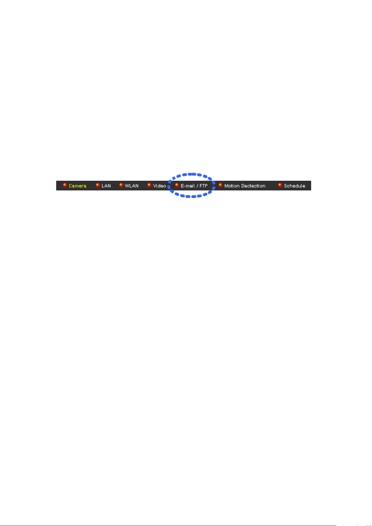
2.5 Email & FTP
This IP camera is capable to send an Email or perform FTP upload with
captured image, when a motion is detected. This is very convenient since IP
camera will guard the environment automatically for you, and you don‟t have to
look at the monitor all the time.
You can access this menu by clicking „E-Mail & FTP‟ on the top of web
management interface.
The instructions of Email and FTP settings will be given below.
44
Page 45
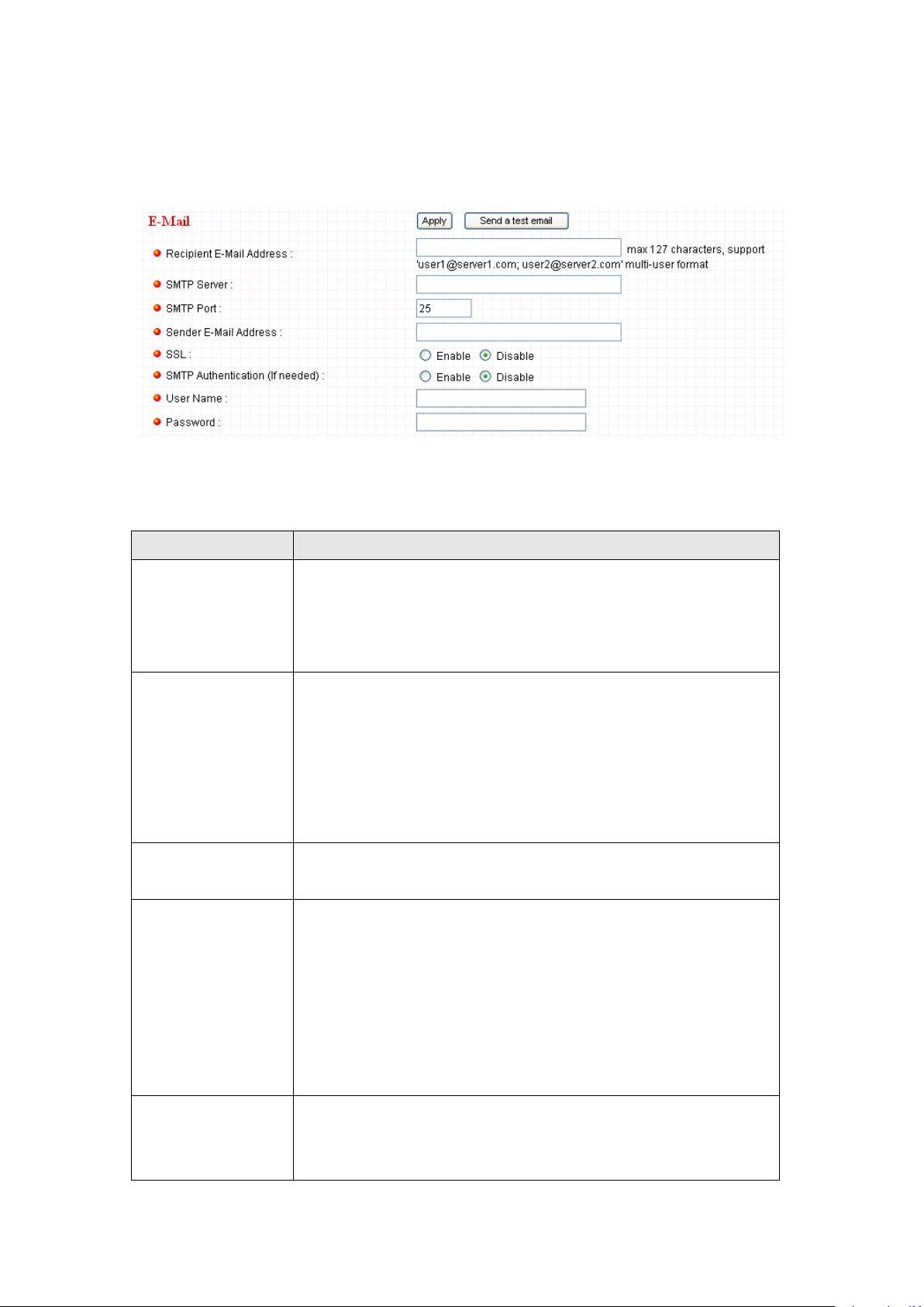
2.5.1 Email Settings
Item
Description
Recipient E-Mail
Address
Input the email recipient‟s Email address here. If you
have more than one Email recipient, please add a ;
(semicolon) mark between every Email address. All
characters shouldn‟t exceed 127 characters.
SMTP Server
Input the IP address or host name of the SMTP server
(the server that delivers the Email for you) here.
If you don‟t know, please refer to the SMTP server you‟re
using in your Email software (like Outlook, Outlook
Express etc.), or ask your network administrator or ISP.
SMTP Port
Input mail server‟s SMTP port here. Most of mail servers
use port number 25.
Sender E-Mail
Address
Input the Email address of mail sender, this will help you
to identify the Email sent by this IP camera by sender‟s
Email address.
NOTE: Some mail server would reject to deliver the
Email from unknown sender, it’s recommended to input
your own Email address here, or any other actual one.
SSL
If SSL encryption is required to connect to the SMTP
server, select „Enable‟ or SMTP connection may fail;
select „Disable‟ if your SMTP server doesn‟t support SSL
These settings are used to send the captured picture via Email:
The descriptions of every setting in this menu will be given below:
45
Page 46

encryption. If in doubt, ask your ISP or mail server‟s
administrator.
SMTP
Authentication
Some SMTP server requires mail senders to be
authenticated before they can send Email. If your SMTP
server requires you to do so, please select „Enable‟, or
select „Disable‟ to disable it. If you don‟t know, please
refer to the SMTP server you‟re using in your Email
software (like Outlook, Outlook Express etc.), or ask your
network administrator or ISP.
User Name
Please input the user name of SMTP server here, if your
SMTP server requires the use of authentication.
Password
Please input the password of SMTP server here, if your
SMTP server requires the use of authentication.
Click „Apply‟ to save settings and make the new settings take effect.
After that, you can click „Send a test email‟ to send a testing Email to the
address you set here, so you can make sure the setting you specified here is
correct and working.
46
Page 47
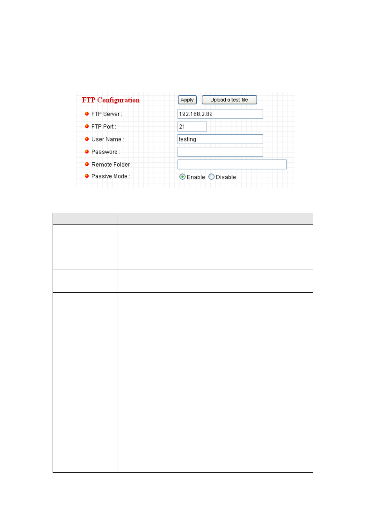
2.5.2 FTP Settings
Item
Description
FTP Server
Input the IP address or host name of the FTP server you
wish to use here.
FTP Port
Input the port number of the FTP server you wish to use
here.
User Name
Input the user name of the FTP server you wish to use
here.
Password
Input the password of the FTP server you wish to use
here.
Remote Folder
Input the remote folder name on the FTP server here. If
nothing is specified here, all uploaded image files will be
placed in FTP server‟s root directory.
Please ask FTP server‟s administrator to know which
folder you should use. Certain user name may have
restrictions and therefore can not place the file in the
directory not owned by the user.
Passive Mode
Select „Enable‟ to use passive mode to send file, or select
„Disable‟ to not to use passive mode to send file.
Some FTP servers require passive mode, if you don‟t
know, please ask FTP server‟s administrator; most of
FTP servers will work fine with both modes, but if you
These settings are used to send the captured picture by FTP:
The descriptions of every setting in this menu will be given below:
47
Page 48

found that non-passive mode is not working, you can try
to use passive mode.
Click „Apply‟ to save settings and make the new settings take effect.
After that, you can click „Upload a test file‟ to send a file to the FTP server you
set here, so you can make sure the setting you specified here is correct and
working.
48
Page 49

2.6 Motion Detection
Item
Description
Motion Detection
Enable
Select „Enable‟ to start motion detection, and select
„Disable‟ to disabled it.
Next Event
Detected Interval
Specify the time interval between two motion detections
in seconds. If a motion is detected after last detection
time, and before next detection time, nothing will be send
by Email or via FTP.
Please specify a time interval that suites your need. If the
time interval is too long, you may not be able to know
what is happened between time interval; if the time
2.6.1 Basic Settings
Motion detection function makes this IP camera become your non-stop guard.
You don‟t have to waste all the time monitoring the images from the camera,
and camera will detect all motions for you. Once motion is detected, a captured
image will be sent to you by Email or via FTP.
You can access this menu by clicking „Motion Detection‟ on the top of web
management interface.
The descriptions of every setting in this menu will be given below:
49
Page 50

interval is too short, you may receive too much
unnecessary images, and consumes too much disk
storage spaces on Email and / or FTP server.
Pre Recording
Time
This option allows the IP cam to capture additional image
frames prior to the event. The duration of pre recording is
based on the settings of Resolution and estimated by the
IP cam automatically.
Recording Time
Select the duration you wish this camera to record image
when a motion is detected from dropdown menu. The
available option of the duration is based on the settings of
Resolution.
Send snapshot
file to Email
Select „Yes‟ to send a picture to the Email address you
specified in „E-Mail & FTP‟ menu when a motion is
detection, and select „No‟ to disable this function.
E-Mail Subject
Set the subject of Email being sent here. This will help
you to distinguish the Email sent by this IP camera from
others.
Send snapshot
file to FTP
Select „Yes‟ to send a picture to the FTP server you
specified in „E-Mail & FTP‟ menu when a motion is
detection, and select „No‟ to disable this function.
Click „Apply‟ to save settings and make the new settings take effect.
50
Page 51

2.6.2 Setup Motion Detection Regions
If you only want to be notified when motion is detected in certain area of
captured image, you can use this function and motions outside of motion
detection region will be ignored, so you won‟t receive too much „useless‟
notifications.
This IP camera supports up to 3 motion detection regions. To setup detection
region, Please use your mouse to drag and resize motion detection regions
marked as „Region1‟, „Region2‟, and „Region3‟ (appear as yellow, green, and
red squares on image:
Motion detection region settings can be found at the bottom of this page:
51
Page 52

The descriptions of every setting in motion detection menu will be given below:
Item
Description
Region1 /
Region2 /
Region3
Check the box to enable / disable a certain motion
detection area.
Sensitivity
Control the detection sensitivity of motion detection of
respective motion detection region. When sensitivity is
higher, small changes in image will cause IP camera to
send a Email / FTP notification; if you received too much
unwanted notification, try to set sensitivity to a lower
value.
Refresh
Click this button to take and display a new picture so you
can make real-time adjustments to motion detection
region.
Save
Save current motion detection settings.
52
Page 53

2.7 Schedule
Item
Description
Enable FTP
Schedule
Enable or disable FTP scheduling.
Time Interval
Select the time interval between 2 FTP file transfers.
Available options are:
Upload one image to FTP server every xx second(s)
minute(s) / hour(s) / day(s) / Frame: An image file will be
uploaded to FTP server after the time you specified here
has been passed. Where xx is an integer between ** and
**.
Upload one image to FTP server every xx
Frames/Second: An image file will be uploaded to FTP
server every xx frames / second.
File Control
Control the file overwriting behavior:
You can control FTP / Email image transfer by schedule. Unlike motion
detection, the only key to trigger file transfer is time.
You can access this menu by clicking „Motion Detection‟ on the top of web
management interface.
The descriptions of every setting in this menu will be given below:
53
Page 54

Upload files with filename composed of date / time: When
a file is uploaded, it will be named as the date and time
when the file is uploaded.
Over file with the same filename: When a new file is
uploaded, it will replace the old one with the same file you
specified here.
Enable E-Mail
Schedule.
Enable or disable E-mail scheduling.
Time Interval
Specify the time interval between 2 emails.
Click „Apply‟ to save settings and make the new settings take effect.
54
Page 55

2.8 System
The system menu allows you to set some system-specific parameters, like
password and time setting. You can also upgrade the firmware of this IP
camera, to make new functions available on this IP camera. You may also
clear all settings or reboot the IP camera here.
You can access this menu by clicking „System‟ on the top of web management
interface.
55
Page 56

2.8.1 Camera Information
Item
Description
Camera Name
Please specify the name of this IP Camera here. This can
be used to identify your camera on the network when you
have more than one IP camera in the same network.
Default name begins with „IC-„ plus the last 6 characters
of the MAC address of this IP camera. You can modify
the name to the one you can remember and meaningful
to you, but never give all IP cameras in the same network
with same name.
Password
Please specify user name „admin‟ „s password here. (The
one you need when you log onto web management
interface and use „admin‟ as user name.
Confirm
Password
Please input the same password again, to make sure
there‟s no typo.
Camera information allows you to set the name and administrator‟s password
of this camera.
The descriptions of every setting in this menu will be given below:
Click „Apply‟ to save settings and make the new settings take effect.
56
Page 57

2.8.2 Date / Time Setting
Item
Description
Set Date/Time
manually
Please input the date and time you wish to set here.
Date / time format is YYYY / MM / DD HH:MM:SS
Time is in 24-hour format.
You can click „Synchronize to PC time‟ to use the time of
the computer you‟re using.
Example: 24th August 2007 = 2007/ 08 / 24,
and PM 9:24:30 = 21:24:30
Time Zone
Please select the time zone of the country / city of
resident from dropdown menu here.
NTP Server
Please input the IP address or host name of NTP server
here. You can use default value „pool.ntp.org‟, or ask your
ISP for the IP address or host name, if they have one.
Enable Daylight
Saving Time
Select „Yes‟ if your area of residence uses daylight
saving; if not, select „No‟.
Synchronize to
PC time
Click this button and the IP camera will use the current
time setting of your computer as IP camera‟s time setting.
This setting allows you to change the date and time of the real time clock in
this IP camera. You can set the time manually, or use network time protocol
(NTP) to set the time automatically.
The descriptions of every setting in this menu will be given below:
Click „Apply‟ to save settings and make the new settings take effect.
57
Page 58
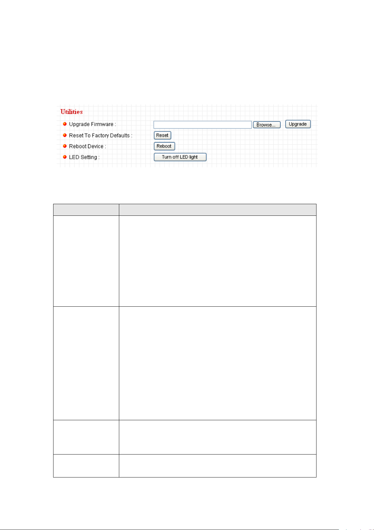
2.8.3 Utilities
Item
Description
Upgrade
Firmware
If you downloaded latest firmware file from our website,
you can click „Browse‟ button to pick the firmware file you
wish to use. Then click „Upgrade‟ button to start firmware
upgrade procedure.
It’s recommended to use wired Ethernet connection
when you use this function, and DO NOT DISCONNECT
OR CLOSE WEB BROWSER DURING UPGRADE!
Reset
Clear all settings in the camera. Please think again
before you do this, and then click this button to reset all
settings.
NOTE: IP address will be reset to default value
‘192.168.2.3’ also. You’ll need to change the IP address
setting of your computer if the IP address of your
computer does not begin with ‘192.168.2’, and subnet
mask is not ‘255.255.255.0’, or you’ll not be able to
connect to this IP camera again.
Reboot Device
If you found the IP camera is responding slowly or
behaves strange, you can click this button to try to reboot
the IP camera, this may help.
LED Setting
Switch the LED light of this IP camera off, so „LAN‟ and
„WLAN‟ LED on the IP camera will stop working, in case
This menu allows you to upgrade firmware, clear all settings, reboot the IP
camera, and switch LED lights on/off.
The descriptions of every setting in this menu will be given below:
58
Page 59

you don‟t want other people know the camera is
transferring data.
You can click this button again to switch LED lights on
again.
59
Page 60

2.9 Status
This menu provides all information about this IP camera, like firmware version,
system uptime, date / time, and network information.
You can access this menu by clicking „Status‟ on the top of web management
interface.
60
Page 61
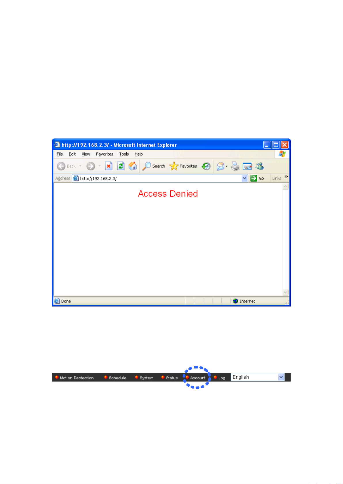
2.10 Account
If you wish to allow other people to view the image captured by this camera,
but don‟t want to allow them to modify system settings, you can give them
user-level user name and password, so they can only view the image and can
not change any system setting. When they want to click menus other than
„Camera‟, they will see the following message informing that they don‟t have
permission to do that:
This IP camera supports up to 16 user accounts.
You can access this menu by clicking „Account‟ on the top of web management
interface.
Note: only one user (including administrator) will be able to view the image of
IP camera at the same time.
61
Page 62

The descriptions of every setting in this menu will be given below:
Item
Description
Login
Specify the user name here. Please use alphanumerical
characters (0 to 9, A to Z, and a to z). Not using symbols
and space.
Password
Specify the password for this user here.
Confirm
Password
Specify the password for this user here again.
Authority
Select „Operator‟ and this user will be able to change the
settings of IP camera; select „Guest‟ and this user can
only view the image.
Add
Click „Add‟ to add a new user with the information listed
above.
Modify
To modify the information of an existing user, select his /
her user account, change the information, and then click
this button to save changes.
Remove
Select an existing user and click this button to remove it.
62
Page 63

2.11 Log
All activities of this IP camera will be logged, and you and enter „Log‟ menu to
view these logs.
You can access this menu by clicking „Log‟ on the top of web management
interface.
Click „Refresh‟ to get latest update.
63
Page 64

2.11 Language Menu
This IP camera‟s user interface supports multiple languages. To change
language, click „Language‟ dropdown menu:
Select a language you wish to use from dropdown menu to change displaying
language.
64
Page 65

Chapter III: Using Surveillance Software
3-1 Installing IP Camera Surveillance Software
The IP camera surveillance software provides various functions like video
recording, after this software is installed, you can use your IP camera to
safeguard your property. Please follow the following instructions to install the
surveillance software.
1. Click “16 channel viewer” in supplied CD-ROM, when the following window
appears, click „Next‟.
2. You can specify the destination folder of software installation, you can just
use the default folder, and click „Next‟ to continue.
65
Page 66

3. If you need installation program to create a desktop icon or a quick launch
icon for you, click all items you need here, than click „Next‟ to continue.
66
Page 67

4. Here lists all options you chose in previous steps, if everything‟s correct,
click „Install‟ to start installing procedure, or click „Back‟ to go back to previous
step to modify installing settings.
5. The installing procedure will take some time, please be patient.
67
Page 68

6. When you see this window, it means the software installing procedure is
complete. Please click „Finish‟ to finish the procedure (IP camera surveillance
software will start after you click „Finish‟ button, if you want to start it later,
uncheck „Launch IPCam Surveillance Software‟ box).
68
Page 69

3-2 Using IP camera surveillance software
Before you start:
IP camera surveillance software will only work when your monitor’s
resolution is ‘1024 x 768’. Please change the resolution before you
use IP camera surveillance software, or it won’t start.
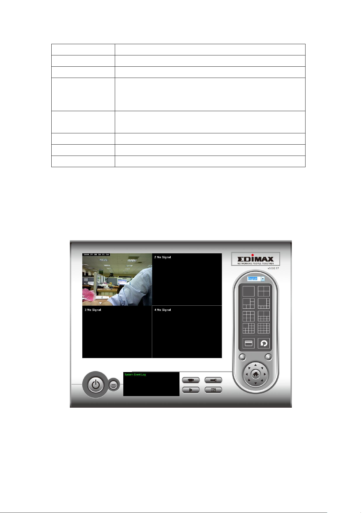
Video displaying area
Language
Display
layout
Full screen /
Scan
Zoom Out /
Zoom In
PTZ Control /
Home
Recording / System configure
Playback / Snap shot
Message display
box
Close window (stop surveillance) /
Minimize window
You can click „IPCam Surveillance Software‟ icon from desktop, quick launch
bar, or start menu to start the IP camera surveillance software.
Here are descriptions for all components of IP camera surveillance software:
69
Page 70
You can put the mouse cursor on a certain component and see its button name,
Item
Description
Video displaying
area
The image of all connected cameras will be displayed
here.
Language
Select a language from this dropdown menu to change
display language.
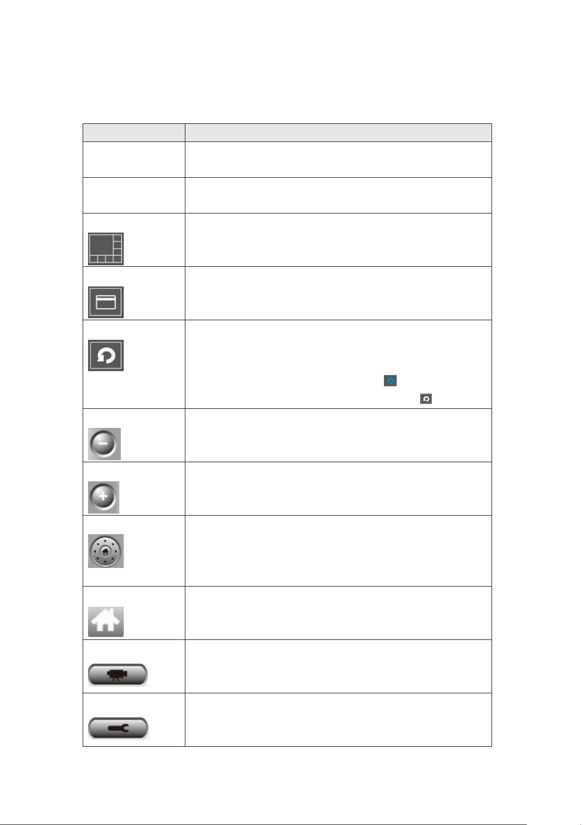
Display layout
Change camera image display layout (Click a layout icon
to change camera display layout). There are 8 kinds of
available display layouts.
Full screen
Click this button to switch to full screen mode (only
display all camera‟s image), press „ESC‟ key to quit full
screen mode.
Scan
Click this button and the IP camera surveillance software
will switch displaying the image of all connected camera
automatically. Click this button once to activate scan
function (scan icon will become blue ), click again to
stop scanning (scan icon will become white ).
Zoom out
Zoom-out (To see more objects).
This function is only available for supported cameras.
Zoom In
Zoom-in (Too see more details).
This function is only available for supported cameras.
PTZ control
There are 8 directions in PTZ control ring. If the camera
you connect support PTZ, you can use PTZ control ring
to change the direction that camera points to.
This function is only available for supported cameras.
Home
Click this button to return the camera to „Home‟ (default)
position.
This function is only available for supported cameras.
Recording
Start video recording.
Configure
Software / camera configuration.
and here‟re detailed descriptions of all buttons:
70
Page 71

Playback
Playback a recorded video file.
Snapshot
Take a snapshot of current camera.
Message display
Displays all system messages like camera is
disconnected etc.
Close window
(stop
surveillance)
Terminates IP camera surveillance software.
Minimize window
Minimizes IP camera surveillance software window.
Video displaying
area
Displays the image of all cameras by the display layout
you selected.
71
Page 72

3-3 Configure IP camera surveillance software
Note: If you’re prompted by a windows security alert which asks you if
you want to block ‘IPCamViewer’ program, please click ‘Unblock’
button, of IP camera surveillance software will not be able to function
correctly.
3-3-1 Configure cameras
Before you use this IP camera surveillance software, you must configure the
camera(s) you wish to connect. Please click „System configure‟ button
and a popup menu will appear:
Please select „Configure Cameras‟ to configure cameras:
72
Page 73

3-3-1-1 „Camera‟ tab
Item
Description
Channel
Select the channel number you wish to set.
Camera Search
All cameras found on your local network will be displayed
in „Camera Search‟ box.
Select
Select a camera listed in „Camera Search‟ box, and click
„Select‟ button to fill all parameters of selected camera in
every camera configuration fields.
Refresh
Rescan all cameras on your local network. If you didn‟t
see the camera you expected in „Camera Search‟ box, or
new cameras has been joined to your local network after
last scan.
Name*
Input the name of camera here. Default value is the first 6
bytes of camera‟s MAC address, you can change the
name of camera so you can remember the camera‟s
location of purpose easily.
Model
Displays the model of selected camera, this field can not
be changed.
In this tab you can configure all cameras you wish to connect. Up to 16
cameras can be connected simultaneously:
Here are the descriptions of all setting items:
73
Page 74
IP*
Input the IP address of camera.
Username*
Input the user name of camera.
Web Port*
Input the web port of the camera. By default it‟s „80‟.
Password
Input the password of camera. Default value is „1234‟.
You should change the password if you changed the
password of selected camera.
Video Format**
Select the video encoding format of this camera (MJPEG
or MPEG4).
Reset
Clear all fields in „Camera Configuration‟ section.
OK
Save settings in this tab.
Cancel
Discard all settings in this tab.
*: It‟s recommended to use „Select‟ button to fill the content of this field.
**: Only available for cameras support this function.
After you‟ve set all channels you wish to set, click „OK‟ to save settings, and if
everything‟s correct, you‟ll see the camera‟s image in IP camera surveillance
software‟s main menu:
74
Page 75

3-3-1-2 Schedule Recording
Item
Description
Channel
Select the channel number you wish to set.
One Time
Schedules
You can specify the one-time schedule for selected
camera; this schedule will be executed once only.
New
(One Time
Schedules)
Click this button and a new window will appear:
In this tab, you can setup scheduled video recording, so you can record the
video captured by all cameras you have by a pre-defined schedule.
Here are the descriptions of all setting items:
75
Page 76
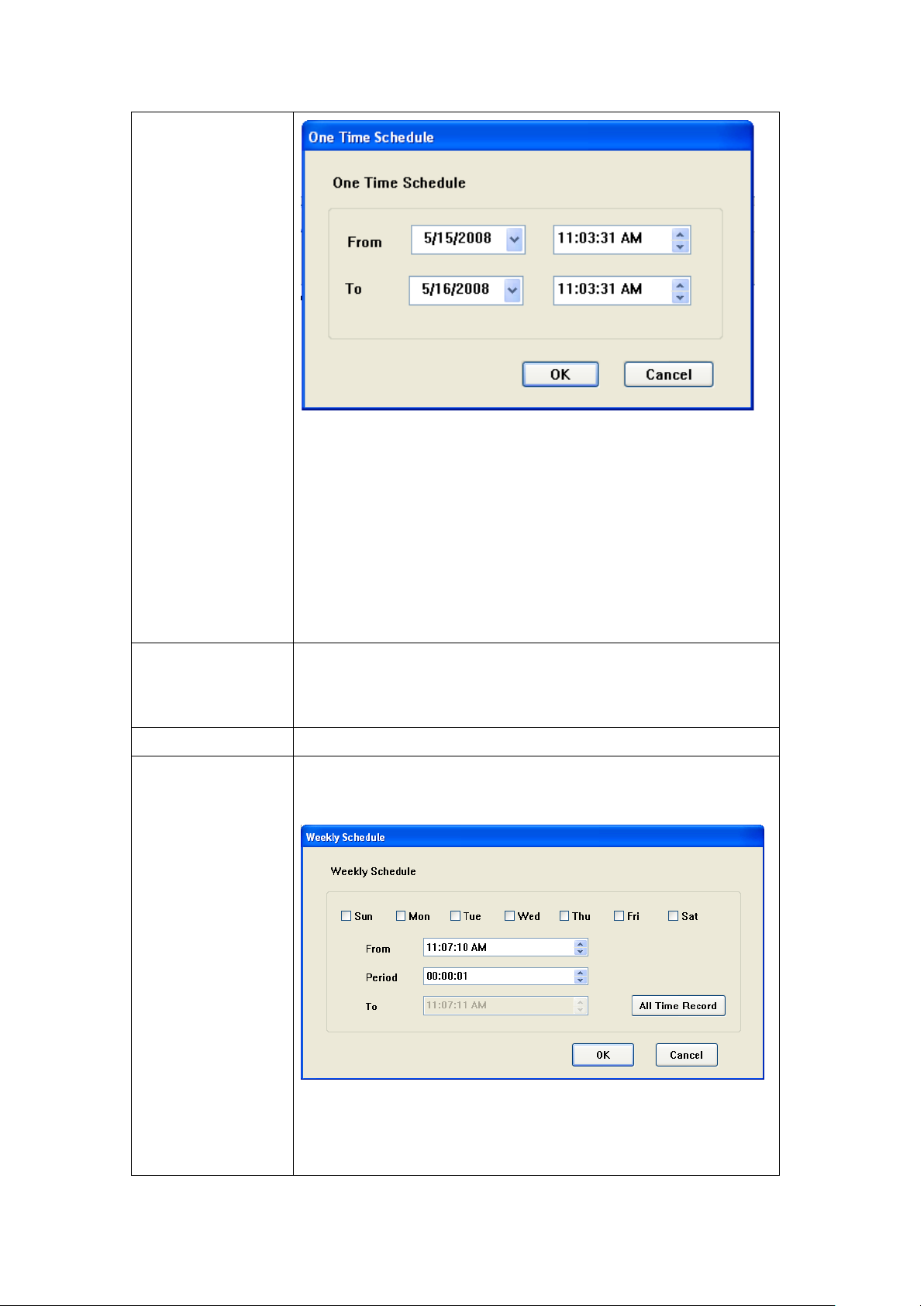
Please specify the time duration of this one-time
schedule (the date and time of „From‟ and „To‟), then click
„OK‟ to save settings.
Please note you must set a schedule that will be
happened in the future, you can not set a schedule in the
past.
Edit
You can modify a scheduled recording item. Select a
schedule in „One Time Schedules‟ list, and click „Edit‟
button to edit the start and end time of this schedule.
Delete
Delete a selected schedule item.
New
(Weekly
Schedules)
Click this button and a new window will appear:
You can define recording schedule that will be executed
at the specified time of certain weekday(s) in a week.
76
Page 77

Please check all weekdays that applies, and set the start
time in „From‟ field. You can set the duration of video
recording in „Period‟ field (format is HH:MM:SS), and the
end time will be calculated automatically and displayed in
„To‟ field. You can also click „All Time Record‟ button to
define a recording schedule that will be executed every
weekday, from 12:00:00AM to 11:59:59PM.
Click „OK‟ to save changes.
Edit
You can modify a scheduled recording item. Select a
schedule in „One Time Schedules‟ list, and click „Edit‟
button to edit the start and end time of this schedule.
Delete
Delete a selected schedule item.
OK
Save settings in this tab.
Cancel
Discard all settings in this tab.
77
Page 78

3-3-1-3 Audio
Item
Description
Channel
Select the channel number you wish to set.
Mute Audio
Check this box and the IP camera surveillance software
will not play the audio captured by this camera.
Record Video
Only
Check this box and the IP camera surveillance software
will not record the audio captured by this camera.
OK
Save settings in this tab.
Cancel
Discard all settings in this tab.
For cameras that support audio, you can use this tab to decide if you wish to
hear the audio captured by selected camera.
Here are the descriptions of all setting items:
78
Page 79

3-3-1-4 Motion Record
Item
Description
Channel
Select the channel number you wish to set.
Enable
Enable motion record function.
Disable
Disable motion record function.
Recording Time
Select the time duration that camera will record when a
motion has been detected from dropdown menu in
seconds.
Invoke alarm
when motion is
triggered
Send an alarm when a motion has been detected by the
camera.
Send mail when
Send an email to a pre-defined address when a motion
WARNING: For applications that security is highly concerned, it’s not
recommended to use this function since some tiny changes you may
need to know may not be able to trigger the camera and the camera
will not start recording.
With this function activated, only motions captured by the camera will be
recorded, so you don‟t have to waste hard disk storage space on images you
don‟t need to pay attention to.
Here are the descriptions of all setting items:
79
Page 80

motion is
triggered
has been detected by the camera.
OK
Save settings in this tab.
Cancel
Discard all settings in this tab.
80
Page 81

3-3-2 General Settings
Item
Description
Data Directory
Set the directory (folder) you wish to store the recorded
video and captured image. You can click „Browse‟ button
to pick a directory in your hard disk.
Free Recording
Space
Displays remaining storage space.
Max Video File
Size
Defines the maximum file size of every video file. When
the size of file exceeds this value, IP camera surveillance
software will open another file to record the video.
You can set system-wide settings of this IP camera surveillance software in
this menu.
3-3-2-1 „General‟ tab
All general settings like file storage directory and recording spaces can be set
here.
Here are the descriptions of all setting items:
81
Page 82

Scan Time
Define the time period to pause between every camera
switch when you activate „Scan‟ function.
Cycle Recording
You can decide the behavior when hard disk space is full:
Disable: Do not overwrite recorded video files.
Enable: Overwrite recorded video files.
OK
Save settings in this tab.
Cancel
Discard all settings in this tab.
82
Page 83

3-3-2-2 „E-Mail Setting‟ tab
Item
Description
E-Mail Subject
Specify the subject of sending email.
Recipient E-Mail
Address
Here lists all email addresses you set.
New
Click this button and you‟ll be prompted to input the email
address. Click „OK‟ to save changes.
If you want to use motion detection function and wish to get an email that
contains the image captured by the camera, please setup your email related
parameters here first.
Here are the descriptions of all setting items:
83
Page 84

Edit
Select an email address from „Recipient E-Mail Address‟
box, and click „Edit‟ to edit the email address.
Delete
Delete selected email address.
Sender E-Mail
Address
Specify the email address of email sender.
SMTP Server
Specify the IP address or host name of the SMTP server
you wish to use. For most of ISPs they will only allow its
subscriber to use their SMTP server, if you don‟t know
which SMTP server you should use, please refer to the
setting of your email software or ask your ISP / network
administrator.
SMTP port
Specify the port number of the SMTP server you wish to
use here. By default (and the setting of most of SMTP
servers) it‟s „25‟.
SMTP Auth
Select „Enable‟ if your SMTP server requires
authentication, select „Disable‟ if it‟s not required. If you
don‟t know if your SMTP server requires authentication,
please refer to the setting of your email software or ask
your ISP / network administrator.
SMTP Account
Input the SMTP account (username) of your SMTP
server here. In most cases, it‟s the same with your POP3
username (the one you used to receive email). Please
refer to the setting of your email software or ask your ISP
/ network administrator if you‟re not sure about this.
SMTP Password
Input the SMTP password of your SMTP server here. In
most cases, it‟s the same with your POP3 password (the
one you used to receive email). Please refer to the
setting of your email software or ask your ISP / network
administrator if you‟re not sure about this.
OK
Save settings in this tab.
Cancel
Discard all settings in this tab.
84
Page 85

3-3-2-3 Security
If you don‟t want other people to access this IP camera surveillance software,
you can set a password to protect it.
You‟ll need to input the password every time you wish to use this IP camera
surveillance software:
To set password, please use „Security‟ tab in „General Options‟ menu:
85
Page 86

Here are the descriptions of all setting items:
Item
Description
Enable
Requires password authentication when this software
starts.
Disable
Password authentication is not required when this
software starts.
Password
Input the password you wish to use here.
Confirm
Password
Input the password you wish to use here again.
3-3-2-4 About
This tab shows the version number of the IP camera surveillance software
you‟re using.
86
Page 87

3-4 Change Display Layout
Layout style 1: 1
Camera only
Displays the video of 1 camera only.
Layout style 2: 4
Cameras
Displays the video of up to 4 cameras.
This IP camera surveillance software provides 8 kinds of display layout:
Every layout displays different number of camera and camera arrangement,
you can click the icon that presents a specific kind of layout, and the video
displaying area will change accordingly.
87
Page 88

Layout style 3: 6
Cameras
Displays the video of up to 6 cameras.
Layout style 4: 8
Cameras
Displays the video of up to 8 cameras.
Layout style 5: 9
Cameras
Displays the video of up to 9 cameras.
Layout style 6:
10 Cameras
Displays the video of up to 10 cameras.
88
Page 89

Layout style 7: 13
Cameras
Displays the video of up to 13 cameras.
Layout style 8: 16
Cameras
Displays the video of up to 16 cameras.
89
Page 90

3-5 Full-screen mode
If you want to use all available spaces on your monitor to display surveillance
image, you can click „Full Screen‟ button to switch display mode to full-screen
mode.
To exit full-screen mode, press „ESC‟ key.
90
Page 91

3-6 Scan
NOTE: If a camera is configured but disconnected, it will still be
displayed in a scan sequence (you’ll see nothing and you’ll see
‘Disconnected’ text displayed at the upper-left corner of display
image).
If you have more than one camera configured, and you wish to switch the
displaying image between cameras, you can click „Scan‟ button to switch
between all configured cameras.
Click „Scan‟ button once to activate scan function (scan icon will become blue
), click again to stop scanning (scan icon will become white ).
91
Page 92

3-7 Zoom-in / Zoom-out
For cameras that support zoom-in / zoom-out function, you can use this
function to see more objects that fall in the scope of camera‟s view, or enlarge
the image size of a certain object to see its detail.
Please select a camera in video displaying area by clicking on its image, then
click button to see more objects that fall in the scope of camera‟s view, or
click to enlarge the image size of a certain object to see its detail (Before
zoom-in, you may need to use PTZ buttons - described in next section) to find
an object you wish to see its detail).
92
Page 93
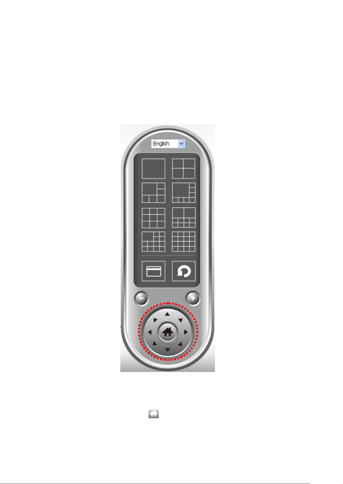
3-8 PTZ
For cameras that support pan - tilt function ( but this model doesn‟t support
PTZ function), you can change the position that camera points to, to see
different places that fall in the scope of camera‟s view.
Please select a camera in video displaying area by clicking on its image, and
then click the directions you wish the camera to move to (total 8 directions
available). Click „Home‟ button ( ) to return to camera‟s home (default)
position.
93
Page 94

3-9 Snapshot
You can take a snapshot of selected camera and save it to „Snapshot‟
sub-folder of pre-defined data directory.
Click snapshot button once to take a snapshot; you can take as much
snapshot as you want before hard disk is full.
94
Page 95

3-10 Recording
You can start video recording of selected camera manually by clicking „Start
Recording‟ button:
When recording starts, you‟ll see a message displayed in message displaying
box like „1/1 10:00:00, Camera 2 Start Manual‟, which means camera 1 starts
recording manually on 1/1 at 10:00:00.
To stop recording, click „Start Recording‟ button again, and you‟ll see a
message displayed in message displaying box like „1/1 10:00:00, Camera 2
Stop Manual‟.
95
Page 96

3-11 Video Playback
You can playback all recorded video by clicking this button.
A new window will appear:
You have to search the video file before you can play it. There are two kinds of
video search: Time Search (search all videos file that falls in a specific period
of time) and Motion Search (search all videos recorded by motion detection
function and falls in a specific period of time).
Please define the start and end date / time of the time period you wish to
search, and then click „Search‟ button (of „Time Search‟ of „Motion‟ Search‟). All
found videos will be displayed, select the video you wish to play and click „Play‟
button to playback.
96
Page 97

Chapter V: How to View IP Camera over the Internet with
iPhone
IC-3005 series features iPhone support for iPhone users to monitor their home
using Edimax IP-Cameras.
Please check following instruction for installation. The following instruction
applies to all Edimax routers
Step1:
Ensure My-PC is Internet-ready via Router
Step 2:
Check with your ISP (Internet Service Provider) whether a Public and
fixed IP address is assigned to you. An IP address is like an unique phone
number that is totally different from all the others‟ for calling a particular person.
You could browse the Internet or monitor your home over the Internet with
iPhone by using this unique IP address. Therefore, an unique IP address is a
Public and fixed IP address. With this, it‟s much easy for iPhone monitoring
your home. For example, an IP address looks like numbers separated with a
dot as: 192.168.2.3
(1) Fixed and public IP address:
All IP addresses different from the following are fixed and public IP address
10.0.0.0 - 10.255.255.255
172.16.0.0 - 172.31.255.255
192.168.0.0 - 192.168.255.255
Write down this IP address and go to Step 3. In this guide, we use a hypothetic
IP address, 61.61.61.1 (yours is different)
(2) Dynamic IP address
If your ISP service staff cannot tell you what IP address is for you, you can
still monitor your home with iPhone, but it turns more complicated.
Your IP address for browsing Internet will change by hours or by days.
Over 90% chance, you may get a dynamic IP address. There is a solution
called Dynamic DNS (DDNS) for free. With this, you could register a name
like http://my-name.dyndns.org for example to find out Edimax IP camera in
the I-Phone. To apply for this, refer to the Appendix “How to apply for a free
97
Page 98

DNS account in the http://www.dyndns.org ” In this guide, we assume you
have already got http://my-name.dyndns.org. (yours may vary) and go to Step
3.
Step 3:
Configure the 1st Camera based on the following:
Configure the 2nd Camera based on the following:
98
Page 99

Configure the Broadband Router based on the following:
99
Page 100

Step 4:
Configuration for iPhone.
(1) Make sure Internet connection is ok with iPhone and click “Safari”
(2) Enter the IP address of your router‟s “fixed and public IP address” (check
the Step 2 for details)
Note: “/ipcam.asp” is needed
If no fixed and public IP address is given by your ISP, you may enter a link like
http://my-name.dyndns.org/ipcam.asp (Again, this link is hypothetic)
You could have your own name like http://john.dyndns.org, mary.dyndns.org
etc. To apply for a free account, refer to the Appendix “How to apply for a free
DNS account in the http://www.dyndns.org “
100
 Loading...