

Page 1

Page 2

Copyright
Copyright Edimax Technology Co., Ltd. all rights reserved. No part of this publication
may be reproduced, transmitted, transcribed, stored in a retrieval system, or translated
into any language or computer language, in any form or by any means, electronic,
mechanical, magnetic, optical, chemical, manual or otherwise, without the prior written
permission from Edimax Technology Co., Ltd.
Edimax Technology Co., Ltd. makes no representations or warranties, either expressed
or implied, with respect to the contents hereof and specifically disclaims any warranties,
merchantability, or fitness for any particular purpose. Any software described in this
manual is sold or licensed as is. Should the programs prove defective following their
purchase, the buyer (and not this company, its distributor, or its dealer) assumes the entire
cost of all necessary servicing, repair, and any incidental or consequential damages
resulting from any defect in the software. Edimax Technology Co., Ltd. reserves the right to
revise this publication and to make changes from time to time in the contents hereof
without the obligation to notify any person of such revision or changes.
The product you have purchased and the setup screen may appear slightly different
from those shown in this QIG. For more information about this product, please refer to the
user manual on the CD-ROM. The software and specifications are subject to change without
notice. Please visit our website www.edimax.com for updates. All brand and product names
mentioned in this manual are trademarks and/or registered trademarks of their respective
holders.
1
Page 3

Contents
Chapter 1: Introduction ..................................................................................................................................... 3
1.1 Product Features .................................................................................................................................. 3
1.2 Application ........................................................................................................................................... 3
1.3 Compatibility ........................................................................................................................................ 3
1.4 System Requirements .......................................................................................................................... 4
Chapter 2: Adapter ............................................................................................................................................ 5
2.1 Ethernet Ports ...................................................................................................................................... 5
2.2 Buttons ................................................................................................................................................. 5
2.3 LEDs ...................................................................................................................................................... 5
Chapter 3: Utility Software Installation ............................................................................................................. 6
Chapter 4: Using the Utility Software .............................................................................................................. 13
4.1 Main Tab ............................................................................................................................................ 13
4.2 Privacy Tab ......................................................................................................................................... 14
4.3 Diagnostics Tab .................................................................................................................................. 15
4.4 About Tab ........................................................................................................................................... 16
Chapter 5: NMK(GROUP) Button ..................................................................................................................... 17
5.1 Forming a HomePlug AV Logical Network ......................................................................................... 17
5.2 Joining a Network .............................................................................................................................. 17
5.3 Leaving a Network ............................................................................................................................. 18
2
Page 4
Chapter 1: Introduction
1.1 Product Features
Transmits network data via existing electrical wires (no external cabling required)
Easy plug-and-play setup
Works with routers, computers, and other network devices
Three Ethernet ports
Easy bandwidth management with port-based QoS
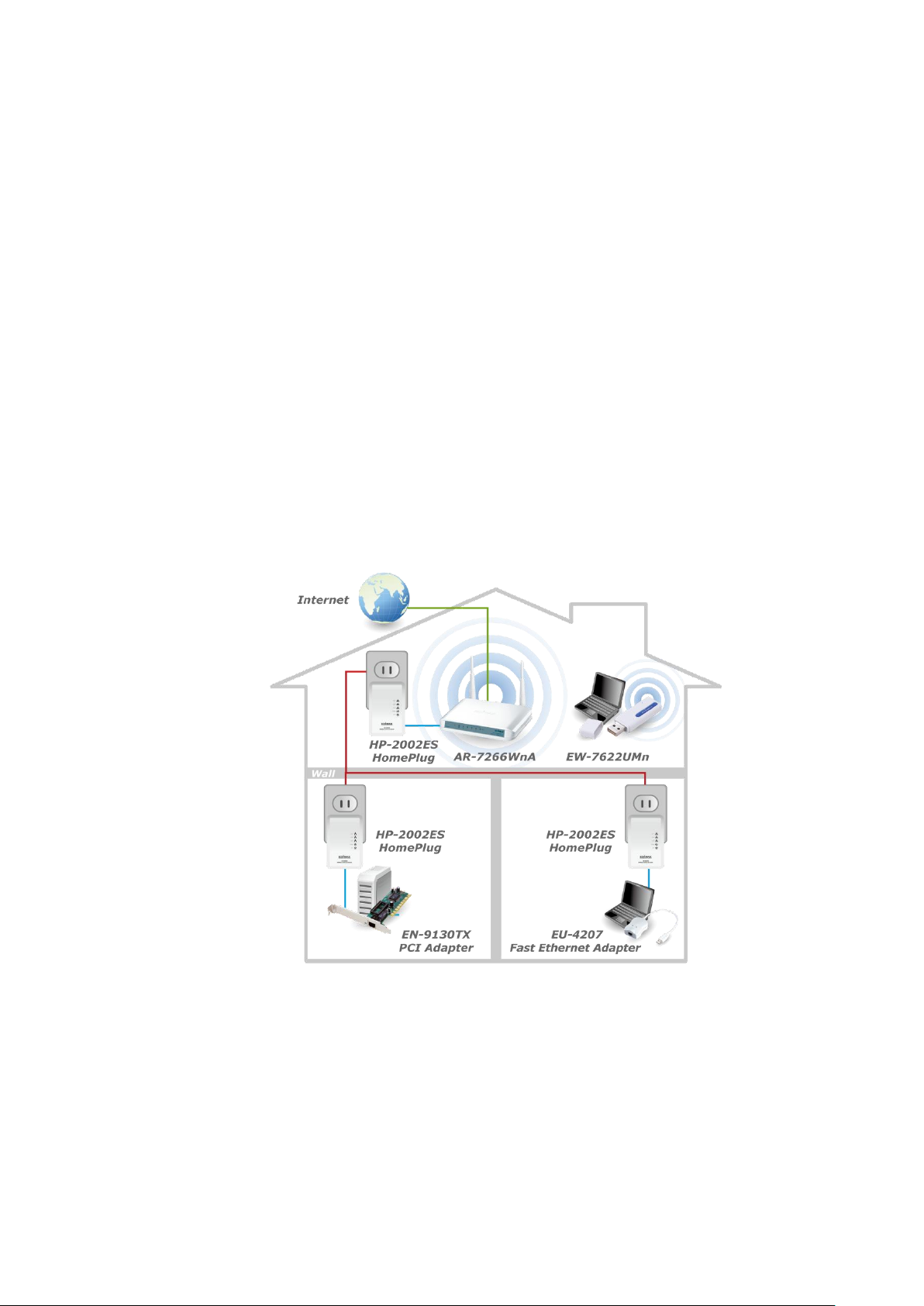
1.2 Application
High-definition (HD) and standard-definition (SD) video distribution
Broadband Internet sharing
Internet Protocol Television (IPTV) and Voice over Internet Protocol (VoIP)
applications
1.3 Compatibility
200Mbps and 500Mbps powerline devices (HomePlug AV standard) are incompatible
and cannot be used with 14Mbps and 85Mbps powerline devices (HomePlug 1.0 and 1.1
standards).
3
Page 5

1.4 System Requirements
Operating System
Windows 2000/XP/Vista/7
CPU
Intel Pentium III 2.0GHz (or higher)
RAM
128MB (at least)
Free Disk Space
20MB (at least)
Network Interface
Fast Ethernet (100Mbps) network interface and an
Ethernet cable
4
Page 6

2.1 Ethernet Ports
Reset
Press and hold the reset button for 3 seconds to restore the
powerline adapter to factory defaults.
Security (Group)
Press and hold the network management key
(NMK(GROUP)) button for more than 10 seconds to
randomize the adapter’s NMK value; or press and hold the
NMK(GROUP) button for 3 seconds to add the powerline
adapter to the existing AV logical network (AVLN).
1-3 (Ethernet Ports)
Indicates activity in the Ethernet connection
Power
Indicates the power status of the powerline adapter
PLC
Indicates activity in the powerline connection
Chapter 2: Adapter
This powerline adapter has 3 Ethernet ports. You can easily give multiple network
devices (like computers, game consoles, HDTVs, and IP cameras) Internet access by
connecting them to the HP-2002ES. Additionally, the HP-2002ES supports port-based QoS.
With a different priority level for each port (high, medium, and low), you can arrange your
bandwidth priority settings simply by making the appropriate connections.
2.2 Buttons
2.3 LEDs
5
Page 7
Chapter 3: Utility Software Installation
Step 1 Before installing the utility software, make sure that no other powerline utility is
installed on your computer. If any other utility software is installed, uninstall it and
reboot the computer.
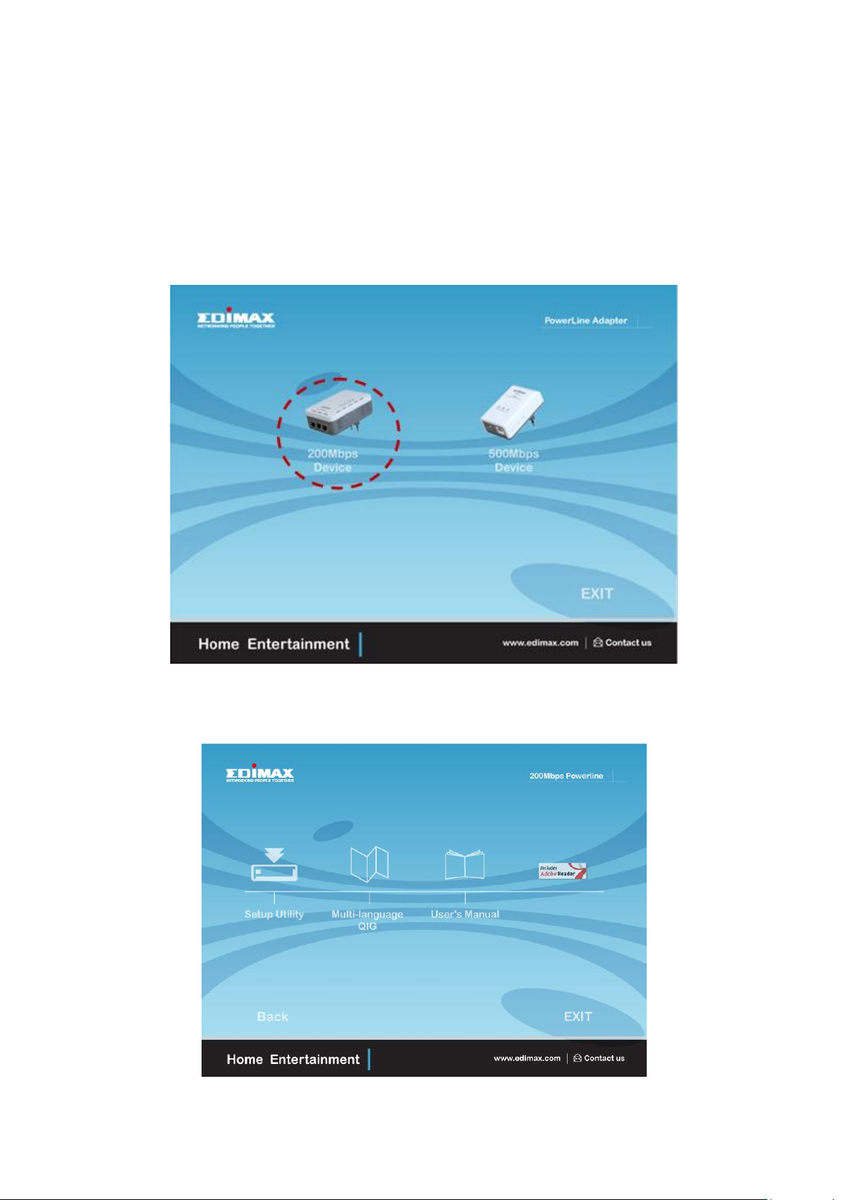
Step 2 Insert the CD into your CD-ROM drive. When the following image appears, click
“200Mbps Device”.
Step 3 Then click “Setup Utility”.
6
Page 8

Note : You will get the following image, if your computer did not install WinPcap4.1.2
before. Please click “Apply” to install WinPcap4.1.2.
7
Page 9

8
Page 10

9
Page 11

Step 4 When the setup wizard appears, click “Next” to continue.
Step 5 Select where you want to install the utility software, and then click “Next”.
10
Page 12

11
Page 13

Step 6 After the installation is complete, click “Close”.
Step 7 An icon will appear on your desktop. Click the icon to open the utility software.
Note: You can manage all the connected powerline adapters with the utility
software. However, installing the utility software is optional.
12
Page 14

Chapter 4: Using the Utility Software
Connect
Click “Connect” and the utility software will scan for other
local powerline adapters.
Rename
Select a device and click “Rename” to rename the device.
Enter Password
By default, this column is blank. Select a device and click
“Enter Password” to set up a password for the device.
Add
This button is used to add a remote powerline adapter to
the existing network.
Scan
Click “Scan” and the utility software will perform an
immediate scan of other remote powerline adapters. By
default, the utility automatically scans every few seconds.
4.1 Main Tab
The “Main” tab provides a list of powerline adapters connected to the computer. The
upper panel displays local powerline adapters. The lower panel displays remote powerline
adapters in the network.
13
Page 15

4.2 Privacy Tab
Set Local Device Only
This button is used to change the network name and
password of the local device.
Set All Devices
This button is used to change the logical network of all
devices that appear in the “Main” tab.
In the “Privacy” tab, you can create a private network by changing the default network
name and configure its security settings. If the network name is modified to anything other
than the default, the network type in the “Main” tab will be changed to “Private”.
14
Page 16

4.3 Diagnostics Tab
The “Diagnostics” tab displays the system information and history of all remote
devices.
The upper panel displays technical data concerning the software and hardware on the
host computer and the lower panel displays the history of all remote devices.
15
Page 17

4.4 About Tab
The “About” tab contains some basic information about the software. You can also
enable or disable the autoscan function under “Preferences”.
16
Page 18

Chapter 5: NMK(GROUP) Button
A
PLC
B
PLC
C
PLC
A and B are not part of AVLN
A and B want to form an AVLN
Press NMK button on A less than 3 sec.
Press NMK button on B less than 3 sec.
A becomes “joiner”
B becomes “joiner”
B determines that A MAC address < B MAC address
B becomes “adder”
A accepts NMK from B
A
PLCAPLC
B
PLCBPLC
C
PLC
A and B are not part of AVLN
A and B want to form an AVLN
Press NMK button on A less than 3 sec.
Press NMK button on B less than 3 sec.
A becomes “joiner”
B becomes “joiner”
B determines that A MAC address < B MAC address
B becomes “adder”
A accepts NMK from B
This section demonstrates how to add or remove devices from a HomePlug AVLN with
the “NMK(GROUP)” button. The “Power” LED indicates the operation status and result.
5.1 Forming a HomePlug AV Logical Network
When two devices with different NMK values are connected to the same powerline and
you want them to form a logical network, follow the following procedures:
Step 1 Press the “NMK(GROUP)” button on device A for less than 3 seconds.
Step 2 Press the “NMK(GROUP)” button on device B for less than 3 seconds. This should
be done within 1 minute.
Step 3 Wait for the connection to complete.
The “Power” LED on both devices will blink evenly at 1-second intervals until the
operation succeeds or fails. If the connection succeeds, it will illuminate steadily. If an error
occurs, the power LED on the adder will blink unevenly until the “NMK(GROUP)” button on
the adder is pressed again or the joiner is reset.
5.2 Joining a Network
If you want to add a new device to an existing network, follow the following
procedures:
Step 1 Press the “NMK(GROUP)” button on the new device for at least 3 seconds.
17
Page 19

Step 2 Press the “NMK(GROUP)” button on any device in the network for less than 3
A
PLC
B
PLC
C
PLC
A and B form an AVLN
C wants to join the AVLN
Press NMK button on B less than 3 sec.
Press NMK button on C less than 3 sec.
B becomes “adder”
C becomes “joiner”
C accepts NMK from B
A
PLCAPLC
B
PLCBPLC
C
PLC
A and B form an AVLN
C wants to join the AVLN
Press NMK button on B less than 3 sec.
Press NMK button on C less than 3 sec.
B becomes “adder”
C becomes “joiner”
C accepts NMK from B
A
PLC
B
PLC
C
PLC
A, B and C form an AVLN
A wants to leave the AVLN
Press NMK button on A more than 10 sec.
A computes random NMK
A resets and restarts
A
PLCAPLC
B
PLCBPLC
C
PLC
A, B and C form an AVLN
A wants to leave the AVLN
Press NMK button on A more than 10 sec.
A computes random NMK
A resets and restarts
seconds. This should be done within 1 minute.
Step 3 Wait for the connection to complete.
The “Power” LED on both devices will blink evenly at 1-second intervals until the
operation succeeds or fails. If the connection succeeds, it will illuminate steadily. If an error
occurs, the power LED on the adder will blink unevenly until the “NMK(GROUP)” button on
the adder is pressed again or the joiner is reset.
5.3 Leaving a Network
If you want to remove a device from an existing network, follow the following
procedures:
Step 1 Press the “NMK(GROUP)” button on the device to be removed for at least 10
seconds.
Step 2 Wait for the device to reset.
The “Power” LED on the device to be removed will momentarily extinguish. It will start
to blink after it has restarted. Then it will illuminate steadily if no error occurs. You can then
disconnect the device.
18
Page 20

19
Page 21

20
 Loading...