

Page 1
Page 2

Copyright© by Edimax Technology Co, LTD. all rights reserved. No part of
this publication may be reproduced, transmitted, transcribed, stored in a
retrieval system, or translated into any language or computer language, in any
form or by any means, electronic, mechanical, magnetic, optical, chemical,
manual or otherwise, without the prior written permission of this company
This company makes no representations or warranties, either expressed or
implied, with respect to the contents hereof and specifically disclaims any
warranties, merchantability or fitness for any particular purpose. Any
software described in this manual is sold or licensed "as is". Should the
programs prove defective following their purchase, the buyer (and not this
company, its distributor, or its dealer) assumes the entire cost of all necessary
servicing, repair, and any incidental or consequential damages resulting from
any defect in the software. Further, this company reserves the right to revise
this publication and to make changes from time to time in the contents hereof
without obligation to notify any person of such revision or changes.
The product you have purchased and the setup screen may appear slightly
different from those shown in this QIG. For more detailed information about
this product, please refer to the User Manual on the CD-ROM. The software
and specifications are subject to change without notice. Please visit our web
site www.edimax.com for the update. All rights reserved including all brand
and product names mentioned in this manual are trademarks and/or
registered trademarks of their respective holders.
Notice according to GNU/GPL-Version 2
This product includes software that is subject to the GNU/GPL-Version 2.
You find the text of the license on the product cd/dvd. The program is free
software and distributed without any warranty of the author. We offer, valid
for at least three years, to give you, for a charge no more than the costs of
physically performing source distribution, a complete machine-readable
copy of the corresponding source code.
Please contact Edimax at: Edimax Technology co., Ltd, NO. 3, Wu-Chuan
3rd RD Wu-Ku-Industrial Park, Taipei Hsien, Taiwan. R.O.C., TEL :
+886-2-77396888, FAX : +886-2-77396887, sales@edimax.com.tw
Page 3

1. Product Introduction
Thank you for purchasing and using Edimax HP-2002AV (or HP-2002AC)
PowerLine 200Mbps Ethernet Adapter. This device allows you to use your
home or office’s existing electrical wiring to create a network for multiple
computers to share files or connecting DVR, X-Box or Set-top Box device to
join the network, or to provide access points for broadband connectivity.
Using the existing AC outlet, you can obtain greater flexibility in arrangement of
a new network with your existing wired or wireless network. No extra cost is
needed.
This product complies with the HomePlug AV mode standard which providing
up to 200Mbps data transfer rate.
This product enables you to create a network easily and cost-effectively, it is a
good choice for you to create a new network or rearrangement of the existing
network.
Note :
14Mbps and 85Mbps Powerline devices (complies with HomePlug 1.0 and 1.1
standards ) can not connect with 200Mbps Powerline devices (complies with
HomePlug A V standard).
1
Page 4

2. Product Package
This package contains the following components:
One PowerLine 200Mbps Ethernet Adapter
* 2pcs for one pair kit package
One RJ-45 Cable (100cm)
* 2pcs for one pair kit package
One Quick Installation Guide
One CD-ROM (Including all the software utilities, drivers, Multi-languages
Quick Installation Guide and User’s Manual)
If any item is missing or damaged, please contact your local resellers for
service.
Note:CD-ROM with the management Utility could help you to manager all of
the HomePlug devices in the LAN. The Utility is not necessary when you use
the internet via HP-2002AV.
2
Page 5
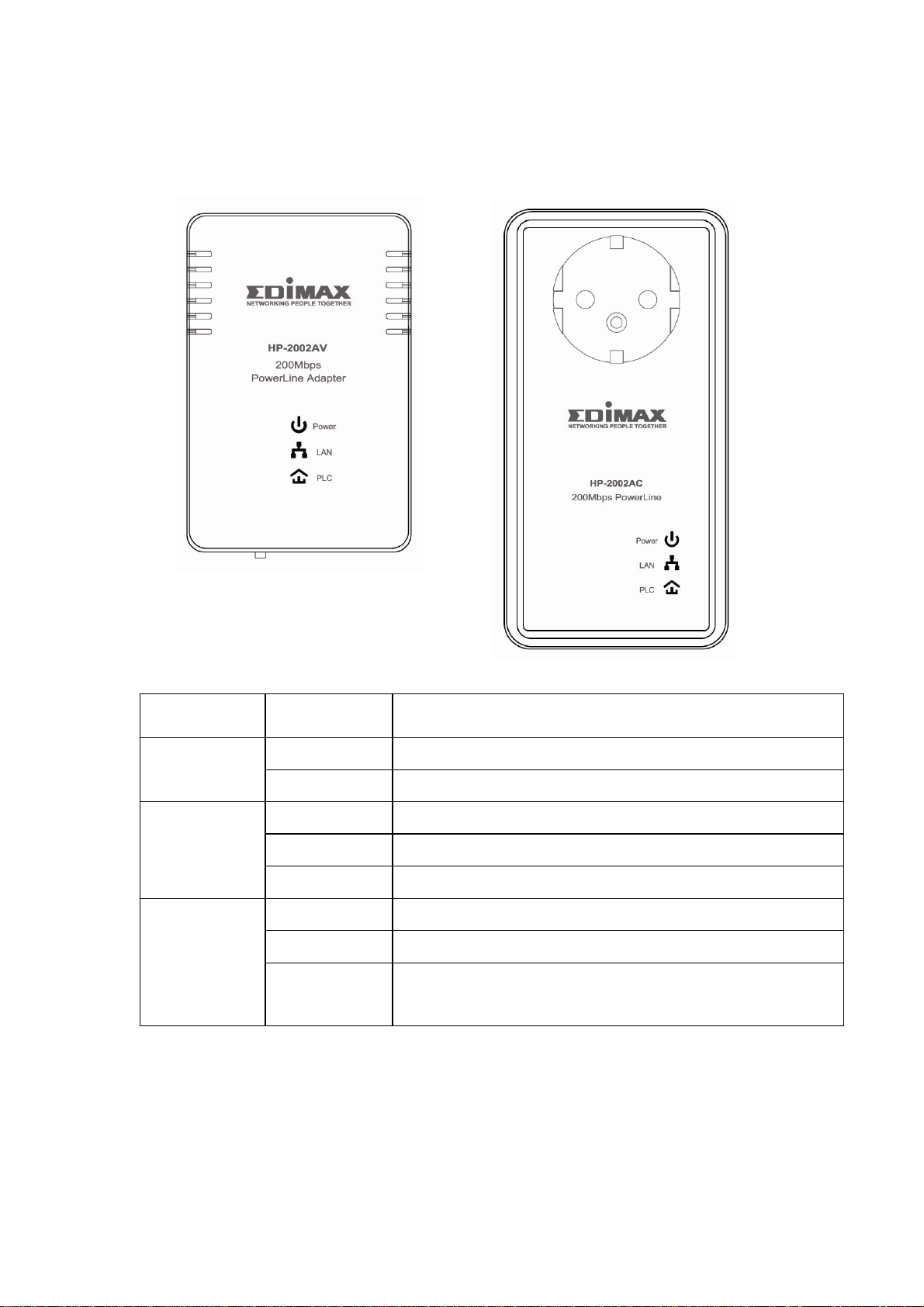
3. LED Definitions
LED Light Status Description
Power
(Green)
LAN
(Green)
PLC
Powerline
On The device is powered on.
Off The device is powered off.
On The LAN cable is connected to the HomePlug.
Off No network connection.
Blinking Network traffic transferring or receiving
On The device detects another powerline device.
Off The device doesn’t detect another powerline device.
Blinking
Network traffic is transmitting via the power port of
the device.
3
Page 6
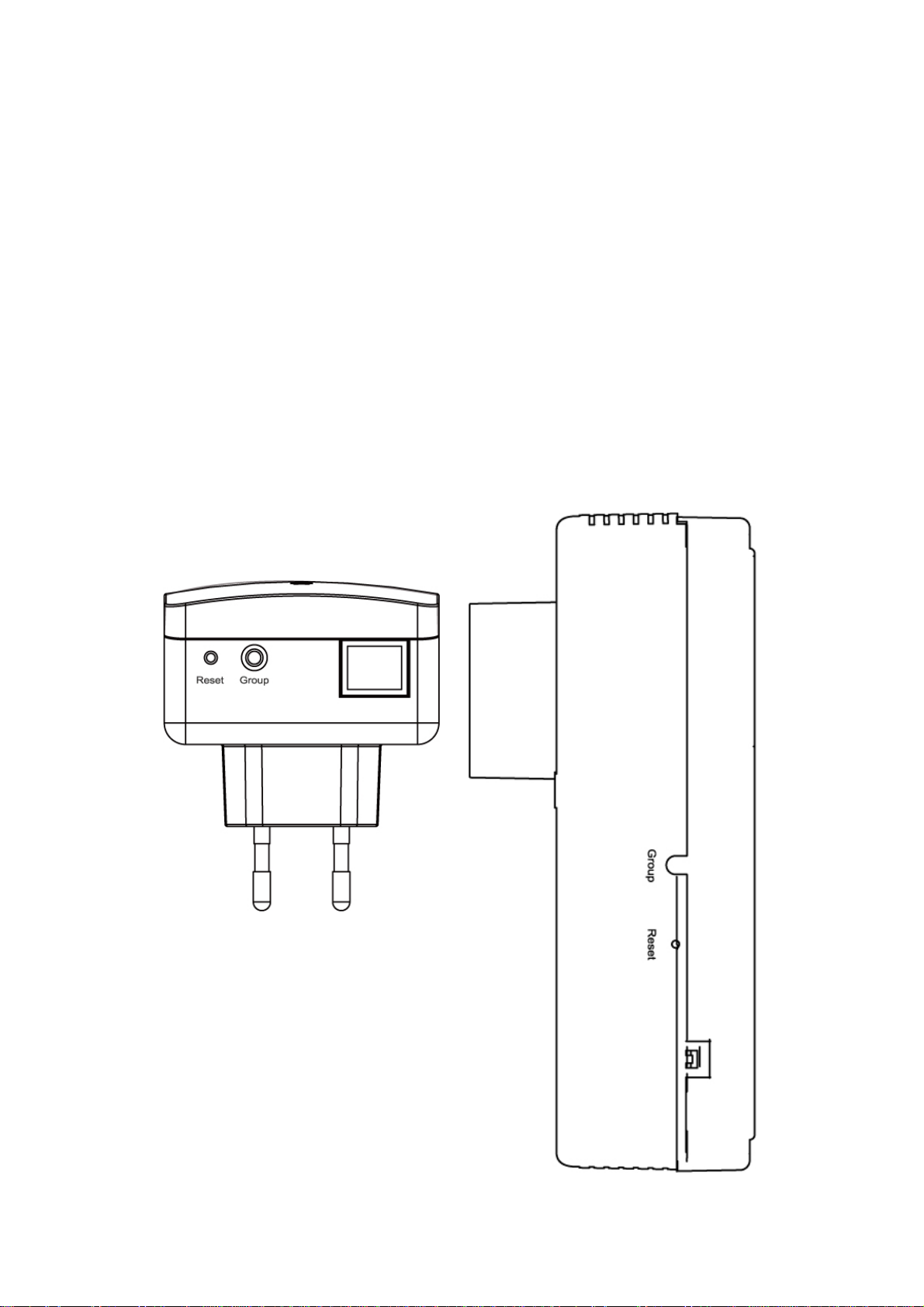
4. Button Definitions
Reset Button and Group Button
The “Group” pushbutton can help you to create several powerline network
groups in LAN . The HomePlug devices in different groups can not
communicate with each other via powerline .
Press the “Reset” pushbutton on the device for less than 3 seconds to reset it
to factory default .
4.1 HomePlug Logical Network
A HomePlug logical network is formed when two or more HomePlug devices
are connected over common powerline and share a common Network
Membership Key (NMK).
4
Page 7

4.1.1 Joining a HomePlug Logical Network
Connect the new device to the powerline. Press the Group pushbutton on the
device for less than 3 seconds. Press the Group pushbutton on another device
connected to the same medium for less than 3 seconds. Wait a few seconds
for the two devices to form a network.
A join operation can be cancelled by pressing the Group pushbutton on the first
device again, for less than 3 seconds, instead of pressing the Group
pushbutton on the second device.
4.1.2 Leaving a HomePlug Logical Network
Press the Group pushbutton on the device for longer than 10 seconds. Wait a
few seconds for the device to reset and leave the network. Disconnect the
device from the powerline. The device is then free to join another HomePlug
logical network.
4.2 Parameter Information Block (PIB)
The PIB, or Parameter Information Block, contains configuration values that
establish device network identity, general capabilities and operational modes.
On boot, the hardware Bootloader copies firmware to SDRAM and starts
firmware execution. The firmware then copies the PIB to SDRAM, reads it and
sets appropriate program variables accordingly. Some PIB settings of general
interest are the MAC Address, Device Access Key (DAK) and Network
Membership Key (NMK).
4.2.1 Reset to Factory Default PIB
Press the Reset pushbutton on the device for less than 3 seconds to reset it to
factory default PIB.
5
Page 8

5. Hardware Installation Procedure
1. Unpack the package and verify that all the items listed in the previous
section are provided.
2. Connect the HomePlug product to the device which you want to add to a
powerline network through the Ethernet cable.
3. Plug the HomePlug product to the power outlet.
4. This device with the HomePlug will join in the powerline network
automatically.
The following is the architecture of various applications of the HomePlug
products.
Picture 1 :
6
Page 9

Picture 2
7
Page 10

6. Software Installation Procedure
The Configuration Utility for Windows 98SE/Me/2000/XP/Vista enables the
users to identify HomePlug devices within the powerline network, measures
data rate performance, ensures privacy and performs diagnostics by setting
user defined secure powerline networks.
The Utility could help you to manager all of the HomePlug devices in the LAN.
The Utility is not necessary when you use the internet via HP-2002AV.
Please follow the procedures below to install the utility. Please note that the
following procedures are running in Windows XP, for other Windows operating
systems, the procedures are similar.
1. Click “ Setup Utility “ to install Utility .
8
Page 11

2. The following screen will be displayed. Click “Next”.
3. Click “Next” to install the utility in the default folder or assign the destination
folder where you would like to install the HomePlug utility.
9
Page 12

4. Click “Finish” to complete the installation.
10
Page 13

7. Edimax PowerLine Utility
Click “Start” and select “All Programs\Edimax PowerLine Utility” in your
computer, you will find the HomePlug utility. Please refer to the following
sections for the descriptions of how to use the utility.
Note :
The Utility can help you to find all (14Mbps / 85Mbps / 200Mbps) Powerline
devies. But the 14Mbps and 85Mbps Powerline devices (complies with
HomePlug 1.0 and 1.1 standards ) can not connect with 200Mbps Powerline
devices (complies with HomePlug AV standard).
7.1 Main
The Main screen provides lists of all HomePlug devices logically connected to
the computer when the utility is running. After connecting a HomePlug device
to your computer, the utility will auto scan other HomePlug devices in the same
network.
11
Page 14

Upper Panel
The upper panel shows all local HomePlug devices connected to the
computer’s NIC (Network Interface Card). In most cases, only one device will
be seen. In situations where there are more than one local device being
connected, such as a USB or an Ethernet adapter, the user can select the local
device by clicking on it and then click the “Connect” to connect to the selected
device. Once connected to the local device, the utility will automatically scan
the power line periodically for any other HomePlug devices.
Lower Panel
The lower panel displays all the HomePlug remote devices, discovered on the
current logical network. In the top of the table, you can see the total number of
remote devices connected on the same network, the Network type (Public or
Private) of the network and the scanning status.
Device Name: shows the default device name, which may be user re-defined.
A user can change the name by either clicking on the “Rename” button or by
clicking on the name and editing in-place.
An icon is usually shown with the name. A color distinction in icons is made
between HomePlug 1.0, HomePlug 1.0 Turbo and HomePlug AV devices. By
default, the icon is always accompanied by a device name.
Password: by default the password column is blank and ‘Enter Password’
button can be used to enter it.
To set the Password of the device (it is required when creating a private
network), first select the device by clicking on its name in the lower panel and
then click on the “Enter Password”. A dialog box will appear. The selected
device name is shown above the password field and the password can be
verified by hitting the OK button. The Password field accepts the Device
password in any case formats, with or without dashed between them.
Note 1: The device must be present on the power line (plugged in) in order for
the password to be confirmed and added to the network. If the device could not
be located, a warning message will be shown.
Note 2: Please find the password of the HomePlug device in the rear panel.
12
Page 15

The “DAK” code is the password.
Quality: the status of the connection quality will be shown here.
Rate (Mbps): show the current data rate of the HomePlug device.
MAC Address: the device’s MAC address will be shown here.
Add Button: it is used to add a remote device to the existing network by
entering the device password of the device. A dialog box will appear as below.
The dialog box allows the user to enter both a device name and the password.
A confirmation box will appear if the password was entered correctly and if the
device was found in the powerline network. If a device was not found, the user
will be notified and suggestions to resolve common problems will be presented.
13
Page 16

Scan Button: the button is used to perform an immediate search of the
HomePlug devices connected to the Powerline network. By default, the utility
automatically scans every few seconds and updates the display screen.
7.2 Privacy
The Privacy screen provides the user with an option to maintain security for
their logical network and also to select the devices that has to be included in
the network.
Private Network Name: All HomePlug devices are shipped using a default
logical network (network name), which is normally “HomePlug”. If you wan to
set a privacy network, change the network name.
Use Default (Public Network): The user can always reset to the HomePlug
network (Public) by entering “HomePlug” as the network name or by clicking on
the “Use Default (Public Network)”.
Set Local Device Only: The button can be used to change the private network
name to all of the local devices. If a new network name is entered, all the
14
Page 17

devices seen on the top panel of Main screen prior to this will be no longer
present in the new network. You have to set the new network name to all local
devices.
Set All Devices: The button is used to set the new network name (network
password) to all HomePlug devices whose password has been entered for the
same logical network. A dialog window will appear to report the success of this
operation. For devices whose password is not entered, this operation will fail
and will report a failure message.
7.3 Diagnostics
The Diagnostics screen shows System information and a history of all remote
devices seen over a period of time.
Upper Panel
The Upper panel shows technical data concerning software and hardware
present on the host computer which were used to communicate over
HomePlug on the Powerline network. It includes powerline network name,
computer user name, MAC Address of all NICs (Network interface card)
connected to the computer, versions of all drivers and utilities, etc.
15
Page 18

Lower Panel
The Lower panel contains a history of all remote devices seen on the computer
over a certain period of time. All devices that were on the powerline network
are listed here along with a few other parameters. Devices that are active on
the current logical network will show a transfer rate in the Rate column; devices
on other networks, or devices that may no longer exist are shown with a “?” in
the Rate column. The following remote device information is available from the
diagnostics screen:
Device Alias Name
Device MAC Address
Device Password
Device Last known rate
Device Last Known Network name
HomePlug chipset manufacturer name
Date device last seen on the network
MAC Firmware Version. (Turbo Only)
The diagnostics information displayed may be saved to a text file for later use,
or can be printed for reference for a technical support call. Devices, which are
not part of the network anymore, can be deleted using the delete button. A
dialog window pops up with a confirmation message if we try to delete a device
whose password has been entered.
7.4 About
The About screen shows the software version information. You can select
“AutoScan” to turn on or off the auto-scan function.
16
Page 19

Warning
(1) Simply plug into a power outlet and do not use a power strip or UPS with
the wall mount device
(2)This is a class A product. In a domestic environment this product may cause
radio interference in which case the user may be required to take adequate
measures.
Important Safety Instructions
This product is intended for connection to the AC power line.
The following pre-cautions should be taken when using this product:
‧Please read all instructions before installing and operating this product.
‧Please follow all warnings and instructions marked on the product.
‧Do not operate this product near water.
‧ This product should never be place near or over radiator, or heat register.
‧ This product relies on a building's electrical installation for short-circuit (over
current) protection.
‧Unplug the device from the wall outlet before cleaning. Use a damp cloth for
cleaning. Do not use liquid cleaners or aerosol cleaners.
17
Page 20

‧Unplug the device from the wall outlet and refer the product to qualified
service personnel for the following conditions :
# If liquid has been spilled into the product
# If the product has been exposed to rain or water
# If the product does not operate normally when the operating instructions
are followed
# If the product exhibits a distinct change in performance.
18
Page 21

19
 Loading...