

Page 1

Document Type: Service Manual
Version 1.1 10162017
SERVICE MANUAL
Multi Zone Cooler
MODEL:
CWR461DZ, CWR262DZ, CWF340DZ, CWR1101DZ,
CWR1551DZ, CWR1551DD, CWR1431TZ
CAUTION: READ ALL SAFETY PRECAUTIONS IN THIS
MANUAL BEFORE SERVICING THE UNIT
EdgeStar, 8606 Wall St, Suite 1800, Austin, TX 78754
support.edgestar.com • service@edgestar.com • edgestar.com
*Warranty service should be performed by an authorized service representative only.
Page 2

CONT
ENTS
- 2 -
SAFETY PRECAUTIONS .............................................................................................................................................................2
PARTS IDENTIFICATION .........................................................................................................................................................3-7
DISASSEMBLY........................................................................................................................................................................8-22
DOOR .......................................................................................................................................................................................8
WOODEN SHELVES................................................................................................................................................................8
WIRES SHELVES.....................................................................................................................................................................8
LAMP………… ....................................................................................................................................................................9-12
DISPLAY BOARD BOARD & CONTROL BOARD............................................................................................................12-15
POWER BOARD & TRANSFORMER ...............................................................................................................................15-16
SENSOR & FAN................................................................................................................................................................16-19
COMPRESSOR PTC STARTER & OVERLOAD PROTECTOR......................................…………………………….…….19-22
TROUBLESHOOTING.........................................................................................................................................................23-26
COMPRESSOR COMPONENTS ..........................................................................................................................................23
ANOTHER ELECTRIC COMPONENT ..................................................................................................................................24
SERVICE DIAGNOSIS CHART.............................................................................................................................................25
REFRIGERATING CYCLE ....................................................................................................................................................26
DESCRIPTION OF PCB .....................................................................................................................................................27-28
SAFETY PRECAUTIONS
Please read the followings before servicing your appliance.
1. Check if an electric leakage occurs in the set.
2. To prevent electric shock, unplug prior to servicing.
3. In case of testing with power on, wear rubber gloves
to prevent electric shock.
4. If you use any appliances, check regular current,
voltage and capacity.
5. Don't touch metal products in cold freezer with wet
hand. It may cause frostbite.
6. Prevent water flowing to electric elements in
mechanical parts.
7. When sloping the set, remove any materials on the
set, especially thin plate type. (ex.: glass shelf or
books.)
8. When servicing evaporator part, wear cotton gloves
without fail. It is to prevent wound by sharp fin of
evaporator.
9. Leave a breakage of refrigerating cycle to a heavy
service center. The gas in cycle inside may soil
ambient air.
Page 3
- 3 -
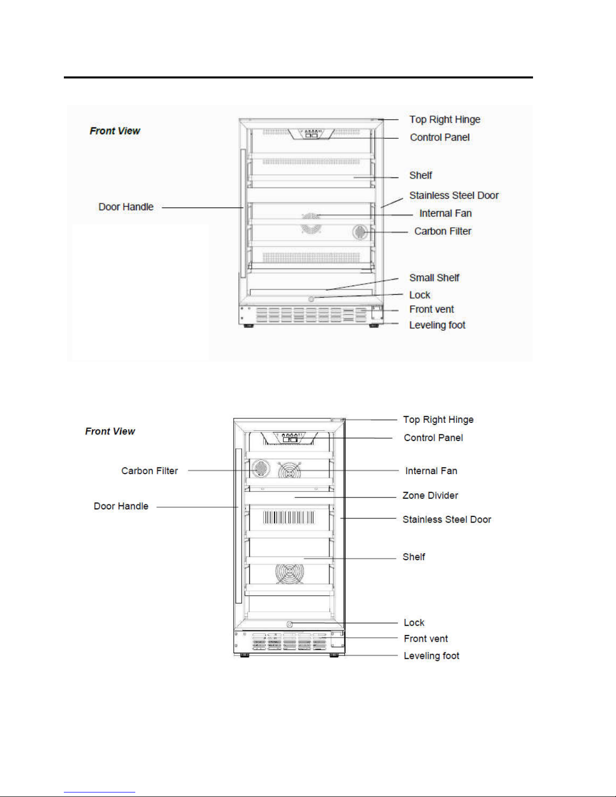
2. PARTS IDENTIFICATION
Model:CWR461DZ
Models:CWR262DZ
Page 4

- 4 -
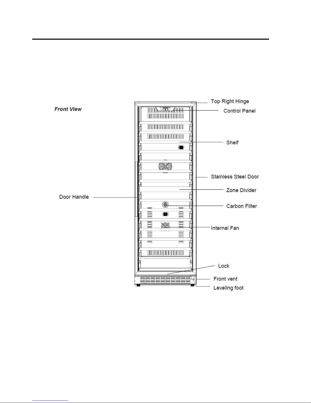
2. PARTS IDENTIFICATION
Models:CWF340DZ
Models:CWR1101DZ
Page 5
- 5 -
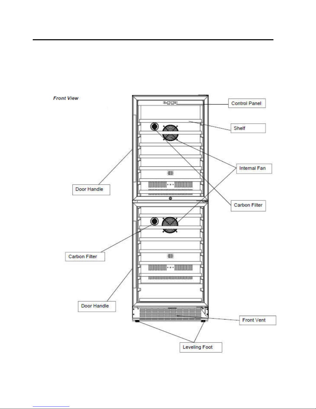
2. PARTS IDENTIFICATION
Models:CWR1551DZ
Page 6
- 6 -
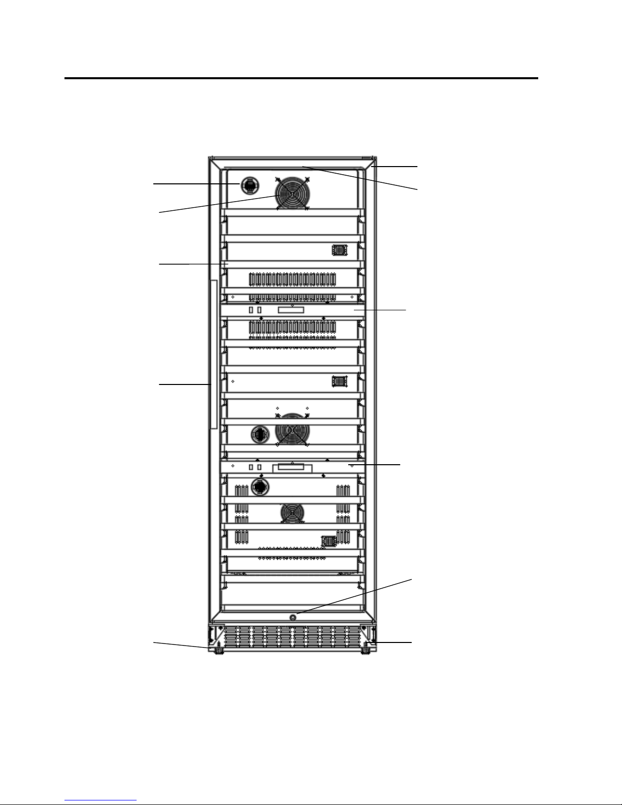
2. PARTS IDENTIFICATION
Models:CWR1551DD
Page 7
- 7 -
2. PARTS IDENTIFICATION
Models:CWR1431TZ
Seamless Stainless Door
Light
Carbon Filter
Internal Fan
Shelf
Door Lock
Lower control Panel
Upper Control Panel
Front Vent
Leveling foot
Door Handle
Page 8
- 8 -
3. DISASS
EMB
LY
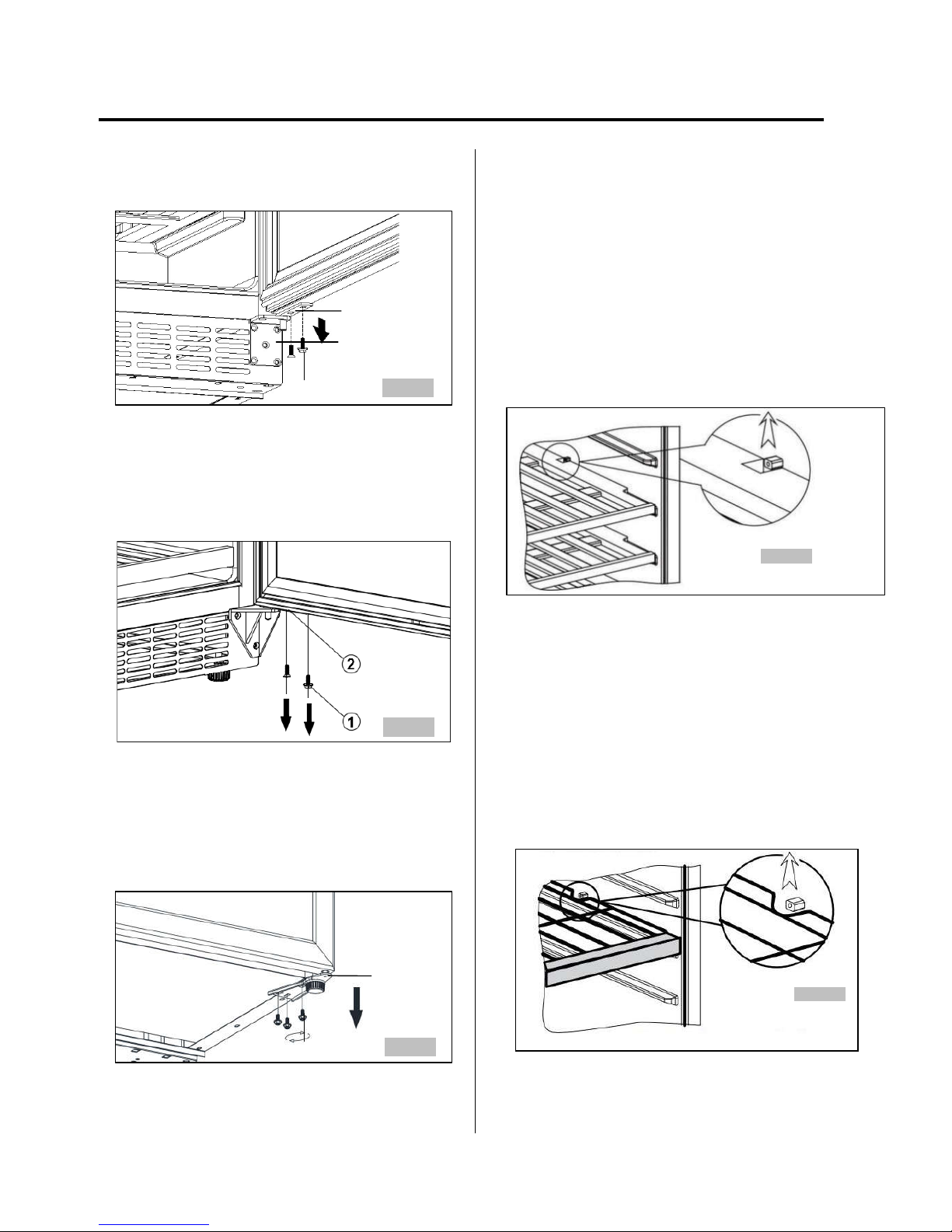
3-1 DOOR
(Models:CWR461DZ , CWR262DZ )
Loosen 2 bolts fixing the lower door axis to the lower
hinge to remove the door. (Figure 1)
Low
er Door Axis
Lower Hinge
BOLT
Figure 1
(Models:CWR1101DZ, CWR1551DZ, CWR1551DD,
CWR1431TZ)
Loosen 2 bolts fixing the lower door axis to the lower
hinge to remove the door. (Figure 2)
Figure2
(Models:CWF340DZ)
Loosen 3 bolts fixing the lower hinge to the cabinet to
remove the door. (Figure 3)
Low
er Hinge
BOLT
Figure3
3-2 WOODEN SHELVES
(Models:CWR461DZ , CWR262DZ
CWR1101DZ, CWR1551DZ, CWR1551DD, CWR1431TZ)
Open the door completely.
If necessary, make sure you remove all the contents sitting
on the shelf..
Pull the shelf forward until the notch aligns with the plastic
post on each side of the shelf track.
Lift the shelf until both notches pass through the posts.
Continue to pull the shelf forward until it is completely
removed from the inner compartment. (Figure 4)
Figure 4
WIRES SHELVES
(Models:CWF340DZ)
Open the door completely.
If necessary, make sure you remove all the contents sitting
on the shelf..
Pull the shelf forward until the notch aligns with the plastic
post on each side of the shelf track.
Lift the shelf until both notches pass through the posts.
Continue to pull the shelf forward until it is completely
removed from the inner compartment. (Figure 5)
Figure 5
Page 9

- 9 -
3. DISASS
EMB
LY
3-3 LAMP
(Models:CWR461DZ , CWR262DZ , CWR1101DZ,
CWR1551DZ ,
LED light in upper zone
1.
Loosen four screws. (figure 6)
screws
Figure 6
2.
Open the electrical box and remove four fixer on the PCB
board. (figure 7)
Figure 7
3. Unplug the led light connector. (figure 8)
connector
Figure 8
4.
Pull out the LED light. The LED light is like below. (figure 9)
Figure 9
LED light in lower zone
1. Loosen one screws. (figure 10)
Figure 10
2. Unplug the led light connector. (figure 11)
Figure 11
5. Loosen two screws. (figure 12)
Screw
Figure 12
6.
Pull out the LED light. The LED light is like below.
(figure 13)
Figure 8
Figure 13
(Models:CWF340DZ)
LED Light in upper zone
1. Loosen four screws. (figure 14)
Figure 14
connector
Page 10

- 10 -
3. DISASS
EMB
LY
2. Unplug the led light connector. (figure 15)
Figure 15
3. Loosen two screws. (figure 16)
Figure 16
4. The LED light is like below. (figure 17)
Figure 17
LED light in lower zone
3. Loosen one screws. (figure 18)
Figure 18
4. Unplug the led light connector. (figure 19
Figure 19
7. Loosen two screws. (figure 20)
Screw
Figure 20
(Models:CWR1551DD )
LED Light in upper zone
1. Loosen four screws. (figure 21)
Figure 21
Screw
2. Pull out the electrical box. (figure 22)
Figure 22
3. Unplug all cable connectors. (figure 23)
4. Press the plastic nail supporting the control board with
forefinger and thumb. (figure 24)
Figure 23
Figure 24
5. The LED light is like below. (figure 25)
Figure 25
co
nnector
Page 11

- 11 -
3. DISASS
EMB
LY
LED light in lower zone
1. Remove four screws from the middle air duct board (figure
26)
Screw
Figure 26
2.
Remove the middle air duct board cover. Unscrew four
screws (figure 27)
Screw
Figure 27
3.
Ta
ke out the complete middle air duct board
(figure 28)
.
Figure 28
5.
Pul
l out the LED light connector
(figure 29)
Light connector
Figure 29
5.Loosen t
he LED light five fixer. Take out the LED light.
(figure 30)
Figure 30
6. The LED light is like below. (figure 31)
Figure 31
(Models: CWR1431TZ )
LED light in upper zone
1. Loosen one screws. (figure 32)
Figure 32
2. Unplug the led light connector. (figure 33)
Figure 33
3. Loosen two screws. (figure 34)
Screw
Figure 34
4. The LED light is like below. (figure 35)
Figure 35
LED
light in middle and lower zone
1. Remove five screws(figure 36)
Screw
Figure 36
co
nnector
Page 12

- 12 -
3. DISASS
EMB
LY
2. Pull ou
t the cover board
(figure 37)
Figure 37
3. Tak
e out the LED light connector
(figure 38)
Figure 38
4. Lossen
the LED light five fixer.
(figure 39)
Figure 39
5.
The LED light is like below. (figure 40)
Figure 40
3-4 DISPLAY BOARD & CONTROL BOARD
(Models:CWR461DZ, CWR262DZ, CWR1101DZ,
CWR1551DZ)
1. Loosen four screws. (figure 41)
2. Pull out the electrical box.
Figure 41
Screw
3.
Unplug all cable connectors. (figure 42)
4. Press the plastic nail supporting the control board with
forefinger and thumb.
Figure 42
5. The control board is like below. (figure 43)
Figure 43
6. Disassemble the display board. (figure 44)
Figure 44
7. The display board is like below. (figure 45)
Figure 45
(Models:CWF340DZ)
1. Loosen free screws. (figure 46)
Figure 46
Page 13

- 13 -
3. DISASS
EMB
LY
2. Push up the top insert Assembly. (figure 47)
Figure 47
3.
Unplug the cable connector. (figure 48)
Figure 48
4. Loosen six screws. (figure 49)
Figure 49
5. The display board is like below. (figure 50)
Figure 50
6. Loosen four screws.
7. Press the plastic nail supporting the control board with
forefinger and thumb. (figure 51)
Figure 51
8.
Unplug all cable connectors.
9. The control board is like below. (figure 52)
Figure 52
(Models:CWR1551DD )
1. Loosen four screws. (figure 53)
Figure 53
Screw
2. Pull out the electrical box. (figure 54)
Figure 54
3. Loosen the two fixer from PCB board. Take out the PCB
board.(figure 55)
Figure 55
3. The display board is like below. (figure 56)
Figure 56
Page 14

- 14 -
3. DISASS
EMB
LY
(Models: CWR1431TZ )
PCB boar
d for lower zone
1. Remove five screws from the air duct board (figure 57)
Screw
Figure 57
2. Pull out the air duct board cover
(figure 58)
Figure 58
3. Unplug all cable connectors. (figure 59)
Figure 59
4. The control board is like below. (figure 60)
Figure 60
5.Remove the six screws from Air duct board C(figure 61)
Figure 61
6.Loosen the display PCB board connector. Pull out the air
duct board C.Take out the front display PCB board cover from
left side(figure 62)
Figure 62
7. Loosen the display PCB board fixer and take out the PCB
board.(figure 63)
Figure 63
8. The display board is like below. (figure 64)
Figure 64
Display PC
B board in upper zone
9. Remove the screws form air duct board (figure 65)
Figure 65
Screw
10. Pul
l out the air duct board cover
(figure 66)
Figure 66
Front cover
Page 15

- 15 -
3. DISASS
EMB
LY
11.Remove the six screws from Air duct board C (figure 67)
Figure 67
12.Loosen the display PCB board connector. Pull out the air
duct board C.Take out the front display PCB board cover from
left side(figure 68)
Figure 68
13. Loosen the fixer from the display PCB board. Take out the
display PCB board(figure 69)
Figure 69
14. The display board is like below. (figure 70)
Figure 70
3-5 POWER BOARD & TRANSFORMER
(Models: CWR262DZ)
1. Remove the screws from the box near compressor. (figure
71)
Figure 71
2. The power board & transformer as below. (figure 72)
Figure 72
(Models:CWR461DZ, CWR1101DZ, CWR1551DZ)
1. Loosen three screws. (figure 73)
Figure 73
2. The power board & transformer are like below. (figure 74)
Figure 74
(Models: CWF340DZ)
1. Loosen three screws. (figure 75)
Figure 75
Front display PCB board cover
Page 16

- 16 -
3. DISASS
EMB
LY
2. The power board & transformer are like below. (figure 76)
Figure 76
(Models:CWR1551DD)
3. Loosen three screws. (figure 77)
Figure 77
4. The power board & transformer are like below. (figure 78)
Figure 78
(Models:CWR1431TZ)
5. Loosen three screws. (figure 79)
Figure 79
6. The power board & transformer are like below. (figure 80)
Figure 80
3-6 SENSOR & FAN
(Models:CWR262DZ)
1. Loosen six screws. Pull out the rear air duct cover.
(figure 8 1 )
fan
Screw
Sensor
Figure 81
2.
Loosen screw. You can replace the sensor ,heater & fan.
(figure 82)
heater
wire housing
screw
evaporator
defrost
sensor
Figure 82
Page 17

- 17 -
3. DISASS
EMB
LY
(Models:CWR461DZ)
1. Loosen six screws. Pull out the rear air duct cover.
(figure 8 4 )
Screw
fan
cold catalyst
Figure 84
2. Loosen 1 screw. You can replace the sensor ,heater &
fan. (figure 85)
evaporator
sensor
heater
wire housing
screw
Figure 85
Models:CWR1101DZ)
1. Loosen screws. Pull out the rear air duct cover. (figure 8 6 )
screw
sensor
fan
Carbon Filter
sensor
fan
Figure 86
2.
Loosen screw. You can replace the sensor ,heater &
fan.(figure 87)
defrost
sensor
evaporator
screw
wire housing
heater
Figure 87
(Models:CWR1551DZ)
1. Loosen screws. Pull out the rear air duct cover. (figure
8 8 )
screw
sensor
fan
Carbon Filter
sensor
fan
Figure 88
2.
Loosen screw. You can replace the sensor,heater & fan.
(figure 89)
defrost
sensor
evaporator
screw
wire housing
heater
Figure 89
Page 18

- 18 -
3. DISASS
EMB
LY
(Models:CWF340DZ)
1. Loosen screws. Pull out the rear air duct cover.
(figure 9 0 )
Screw
sensor
fan
Figure 90
2.
Loosen 1 screw. You can replace the sensor,heater & fan.
(figure 91)
evaporator
sensor
heater
wire housing
screw
Figure 91
(Models:CWR1551DD)
1. Loosen screws. Pull out the rear air duct cover.
(figure 9 2 )
screw
fan
sensor
fan
sensor
Figure 92
2.
Loosen screw. You can replace the sensor ,heater &
fan.(figure 93)
screw
wire housing
heater
evaporator
screw
wire housing
heater
evaporator
Figure 93
(Models:CWR1431TZ)
1. Loosen screws. Pull out the rear air duct cover.
(figure 9 4 )
fan
screw
sensor
fan
sensor
sensor
fan
Figure 94
Page 19

- 19 -
3. DISASS
EMB
LY
2.
Loosen screw. You can replace the sensor ,heater &
fan.(figure 95)
screw
wire housing
heater
evaporator
evaporator
Figure 95
heater
3-7 COMPRESSOR PTC STARTER & OVERLOAD
PROTECTOR
(Models:CWR262DZ)
1. Remove the clamp that is used to fix the compressor
junction box. (figure 96)
Figure 96
2. Remove the compressor junction box. (figure 97)
Figure 97
3. Dismantle the compressor PTC starter and overload
protector. (figure 98)
Figure 98
4. The compressor PTC starter and overload protector is like
below. (figure 99)
Figure 99
(Models:CWR461DZ)
1. Loosen one screw. (figure 100)
Figure 100
Page 20

- 20 -
3. DISASS
EMB
LY
2. Remove the compressor junction box. (figure 101)
Figure 101
3. Dismantle the compressor PTC starter and overload
protector. (figure 102)
Figure 102
4. The compressor PTC starter and overload protector is
like below. (figure 103)
Figure 103
(Models:CWR1101DZ)
1. Loosen one screw. (figure 104)
Figure 104
2. Remove the compressor junction box. (figure 105)
Figure 105
3. Dismantle the compressor PTC starter and overload
protector. (figure 106)
Figure 106
Page 21

- 21 -
3. DISASS
EMB
LY
4. The compressor PTC starter and overload protector is
like below. (figure 107)
Figure 107
(Models:CWR1551DZ, CWR1551DD)
)
1、Open the box near compressor, take out the box.(figure 108)
Figure 108
2、 Remove the compressor junction box. (figure 109)
Figure 109
3. Dismantle the compressor PTC starter and overload
protector. (figure 110)
Figure 110
4. The compressor PTC starter and overload protector
is like below. (figure 111)
Figure 111
(Models:CWF340DZ)
1 .
Opne the box newr compressor and take out the box.(figure
112)
Figure 112
Page 22

- 22 -
3. DISASS
EMB
LY
2.
Dismantle the compressor PTC starter and overload
protector. (figure 113)
Figure 113
3、 The compressor PTC starter and overload protector is
like below. (figure 114)
Figure 114
Models:CWR1431TZ
1.
Open the box near compressor and take out the box(figure
115)
Figure 115
2.
Dismantle the compressor PTC starter and overload
protector. (figure 116)
Figure 116
3. The compressor PTC starter and overload protector is
like below. (figure 117)
Figure 117
Page 23

- 23 -
4. TROUBL
ESHOOTING
1
4-1 COM
PRESSOR COMPONENTS
Check the
resistance of
Motor
Compressor.
2
Check the
resistance of
PTC-Starter.
Check the resistance
among M-C, S-C and
M-S in Motor
Compressor. If its
normal
Check the resistance
of two terminals in
PTC-Starter. If its
normal
YES
NO
Replace Compressor.
YES
NO
2
2 3
3
Replace
PTC-Starter.
3
Check OLP.
Check if applying
a regular OLP.
NO
Replace OLP.
Page 24

- 24 -
4. TROUBLESHOOTING
Check if current flows to the
following components.
Cause.
a. Starting devices
Shorted or broken.
b. OLP
Poor contacting
or shorted.
c. Compressor coil Coil shorted.
d. Circuit Parts
Poor contacting
or shorted.
4-2 ANOTHE
R ELECTRIC COMPONENTS
▼ Cooling is impossible
Compressor
doesn't run.
Replace
each component.
Running state of
Compressor is poor.
Check a starting
voltage.
Low voltage. Raise the voltage.
Check if current flows
to starting devices.
Poor contacting
and broken.
Replace
each component.
Check current flowing
in coil of
Compressor.
Shorted.
Check capacity of OLP.
Lack of capacity.
The items described
above are normal.
Coil of motor
Compressor.
Replace
the compressor.
▼ Cooling ability is poor
Fan motor
doesn't run.
Check Control PCB
Check current flowing
in the Fan Motor.
Poor contacting.
Coil is shorted.
Replace
each component.
Much frost are sticked
to the EVAPORATOR.
Check current flowing
of the following
components.
• Def. Sensor
Shorted.
Replace
each component.
Page 25

- 25 -
4. TROUBLESHOOTING
4-3 SERVICE DIA
GNOSIS CHART
Probl
em
Possible Cause
Appl
iance does not operate.
Not plugged in.
The appliance is turned off.
The circuit breaker tripped or a blown fuse.
Applia
nce is not cold enough.
Check
the temperature control setting. External
environment may require a higher
setting.
The door is opened too often.
The door is not closed completely.
The door gasket does not seal properly.
Turns on and off fr
equently.
The roo
m temperature is hotter than normal.
A large amount of contents has been added to the wine chiller.
The door is opened too often.
The door is not closed completely.
The temperature control is not set correctly. The door
gasket does not seal properly.
The light
does not work.
Not pl
ugged in.
The circuit breaker tripped or a blown fuse. The bulb has
burned out.
The light button is “OFF”.
Energy
conservation button is on.
Vibrations.
Check to assure that the Wine Chiller is level.
The Win
e Chiller seems to make too much noise.
The rattlin
g noise may come from the flow of the refrigerant,
which is normal.
As each cycle ends, you may hear gurgling
sounds caused by the flow of refrigerant in your
Wine Chiller.
Contraction and expansion of the inside walls may cause
popping and crackling noises.
The Wine Chiller is not level.
The door will
not close properly.
The Wine Chiller is not level.
The door was reversed and not properly installed. The gasket is
dirty.
The shelves are out of position.
Displ
ay error code “E1”
The air sensor is open circuit failed. Connection main control
PCB
is with yellow color wires. Check the circuit, if it is normal,
the sensor need to be replaced.
Displ
ay error code “E2”
The air sensor is short circuit failed. Connection main control
PCB i
s with yellow color wires. Check the circuit, if it is normal,
the sensor need to be replaced.
Displ
ay error code “E3”.
The defrost sensor is open circuit failed. Connection main
control P
CB is with red color wires. Check the circuit, if it is
normal, the sensor need to be replaced.
Displ
ay error code “E4”.
The defrost sensor is short circuit failed. Connection main
control P
CB is with red color wires. Check the circuit, if it is
normal, the sensor need to be replaced.
Display error code “E7”.
The air sensor is open circuit failed. Connection main
control P
CB is with white color wires. Check the circuit, if it
is normal, the sensor need to be replaced.
Displ
ay error code “E8”.
The air sensor is short circuit failed. Connection main
control P
CB is with white color wires. Check the circuit, if it
is normal, the sensor need to be replaced.
Page 26

- 26 -
4. TROUBLESHOOTING
4-4 REFRI
GERATING CYCLE
▼ Troubleshooting Chart
LEAKAGE
PA R TIAL
LEAKAGE
Low owing sound of
Refrigerant is heard and
frost forms
A little high more than
ambient room
temperature.
WHOLE
LEAKAGE
Flowing sound of Refrigerant
is not heard and frost isn't
formed.
CLOG
IN CAPILLARY
Flowing sound of Refrigerant
is heard and frost forms
A little high more than
ambient room
temperature.
A little high more than
ambient room
temperature.
A little high more than
ambient room
temperature.
Flowing sound of Refrigerant
is not heard and frost isn't
formed.
YES
No frost or forms
in inlet only
Faulty
Normal amount
Inject Refrigerant to
Observe the discharging
amount of Refrigerant.
No or not much
NO
YES
Compressor.
Compressor and check
cooling operation.
Check Compressor
Clogged or restricted
Normal formed
frost in Evaporator
Find and Repair Leak
Appliance does
not get cold
enough
Appliance does
not get cold at all
Does compressor
turn on?
Is gas leak detected?
Observe refrigerant disharging point. Oil dishcharge/stain is often best indicator. indicator. Use bubbles to locate hole in line,
evaporator or condensor.
No cooling
Is oil leak detected?
• No discharging of refrigerant
• The capillary tube is faulty.
• The lter dryer is faulty.
• The condensor is faulty.
• The evaporator is faulty.
• No discharging of refrigerant
• A little refrigerant discharges
• Normal cooling is possible when
charging refrigerant of regular amount
stated on specication plate / rating
label.
• A little refrigerant discharges
• Normal cooling is possible when
charging refrigerant of regular amount
stated on specication plate / rating
label.
Does frost form on
the evaporator?
Appliance does
not get cold
enough
PARTIAL
RESTRICTION
CAUSE STATE OF UNIT STATE OF EVAPORATOR TEMPERATURE
OF COMPRESSOR
COMMENTS
WHOLE
RESTRICTION
Appliance does
not get cold
NO
Page 27

- 27 -
5.
DE
SCRIPTION
OF PCB
(Models:CWR461DZ, CWR262DZ, CWR1101DZ, CWR1551DZ)
Figure 55
(Models:CWF340DZ)
Figure 57
Page 28

- 28 -
5.
DE
SCRIPTION
OF PCB
(Models:CWR1551DD)
(Models:CWR1431TZ)
Page 29

DATE REVISION NOTES:
9/22/2017 Initial Document
10/16/2017 Minor Text and Title Revision
EdgeStar, 8606 Wall St, Suite 1800, Austin, TX 78754
support.edgestar.com • service@edgestar.com • edgestar.com
*Warranty service should be performed by an authorized service representative only.
 Loading...